JP2005527336A - Solid hydrogel conjugate for ultrasonic imaging and ultrasonic therapy, and acoustic coupling method and hydrogel mass production method thereof - Google Patents
Solid hydrogel conjugate for ultrasonic imaging and ultrasonic therapy, and acoustic coupling method and hydrogel mass production method thereof Download PDFInfo
- Publication number
- JP2005527336A JP2005527336A JP2004508882A JP2004508882A JP2005527336A JP 2005527336 A JP2005527336 A JP 2005527336A JP 2004508882 A JP2004508882 A JP 2004508882A JP 2004508882 A JP2004508882 A JP 2004508882A JP 2005527336 A JP2005527336 A JP 2005527336A
- Authority
- JP
- Japan
- Prior art keywords
- hydrogel
- ultrasonic transducer
- mass
- hydrogel mass
- conjugate
- Prior art date
- Legal status (The legal status is an assumption and is not a legal conclusion. Google has not performed a legal analysis and makes no representation as to the accuracy of the status listed.)
- Pending
Links
- 239000000017 hydrogel Substances 0.000 title claims abstract description 558
- 238000010168 coupling process Methods 0.000 title claims abstract description 51
- 238000004519 manufacturing process Methods 0.000 title claims description 23
- 239000007787 solid Substances 0.000 title claims description 12
- 238000003384 imaging method Methods 0.000 title description 13
- 238000002560 therapeutic procedure Methods 0.000 title description 8
- 229920002401 polyacrylamide Polymers 0.000 claims abstract description 70
- XLYOFNOQVPJJNP-UHFFFAOYSA-N water Substances O XLYOFNOQVPJJNP-UHFFFAOYSA-N 0.000 claims abstract description 40
- 230000008878 coupling Effects 0.000 claims abstract description 37
- 238000005859 coupling reaction Methods 0.000 claims abstract description 37
- 239000003814 drug Substances 0.000 claims abstract description 36
- 238000002604 ultrasonography Methods 0.000 claims abstract description 36
- 229940079593 drug Drugs 0.000 claims abstract description 32
- 239000000203 mixture Substances 0.000 claims description 60
- 239000012530 fluid Substances 0.000 claims description 52
- HRPVXLWXLXDGHG-UHFFFAOYSA-N Acrylamide Chemical group NC(=O)C=C HRPVXLWXLXDGHG-UHFFFAOYSA-N 0.000 claims description 44
- 238000000034 method Methods 0.000 claims description 34
- 238000006116 polymerization reaction Methods 0.000 claims description 34
- 239000000178 monomer Substances 0.000 claims description 22
- 238000010521 absorption reaction Methods 0.000 claims description 15
- 230000000887 hydrating effect Effects 0.000 claims description 13
- 238000002844 melting Methods 0.000 claims description 13
- 230000008018 melting Effects 0.000 claims description 13
- 230000014759 maintenance of location Effects 0.000 claims description 12
- 239000003795 chemical substances by application Substances 0.000 claims description 11
- 230000006378 damage Effects 0.000 claims description 11
- 230000036571 hydration Effects 0.000 claims description 6
- 238000006703 hydration reaction Methods 0.000 claims description 6
- 229920000642 polymer Polymers 0.000 claims description 5
- 238000002360 preparation method Methods 0.000 claims description 5
- 238000002156 mixing Methods 0.000 claims description 4
- 230000000379 polymerizing effect Effects 0.000 claims description 4
- 238000004891 communication Methods 0.000 claims description 3
- 229920002338 polyhydroxyethylmethacrylate Polymers 0.000 claims description 2
- 230000002401 inhibitory effect Effects 0.000 claims 1
- 230000001678 irradiating effect Effects 0.000 claims 1
- 238000003756 stirring Methods 0.000 claims 1
- 239000000463 material Substances 0.000 abstract description 27
- 238000011282 treatment Methods 0.000 abstract description 22
- 238000012285 ultrasound imaging Methods 0.000 abstract description 4
- 238000009210 therapy by ultrasound Methods 0.000 abstract description 3
- 239000000499 gel Substances 0.000 description 84
- 210000001519 tissue Anatomy 0.000 description 29
- 239000000523 sample Substances 0.000 description 23
- 230000001965 increasing effect Effects 0.000 description 11
- ROOXNKNUYICQNP-UHFFFAOYSA-N ammonium persulfate Chemical compound [NH4+].[NH4+].[O-]S(=O)(=O)OOS([O-])(=O)=O ROOXNKNUYICQNP-UHFFFAOYSA-N 0.000 description 9
- 239000008280 blood Substances 0.000 description 9
- 210000004369 blood Anatomy 0.000 description 9
- 230000008901 benefit Effects 0.000 description 8
- 239000000243 solution Substances 0.000 description 8
- 206010028980 Neoplasm Diseases 0.000 description 7
- 238000010586 diagram Methods 0.000 description 7
- 238000010438 heat treatment Methods 0.000 description 7
- 238000002474 experimental method Methods 0.000 description 6
- 239000003999 initiator Substances 0.000 description 6
- KWYHDKDOAIKMQN-UHFFFAOYSA-N N,N,N',N'-tetramethylethylenediamine Chemical compound CN(C)CCN(C)C KWYHDKDOAIKMQN-UHFFFAOYSA-N 0.000 description 5
- 230000000694 effects Effects 0.000 description 5
- 230000008569 process Effects 0.000 description 5
- 238000012360 testing method Methods 0.000 description 5
- 229910001870 ammonium persulfate Inorganic materials 0.000 description 4
- 230000009286 beneficial effect Effects 0.000 description 4
- 230000008859 change Effects 0.000 description 4
- 238000006243 chemical reaction Methods 0.000 description 4
- 230000023597 hemostasis Effects 0.000 description 4
- 238000012886 linear function Methods 0.000 description 4
- 238000012986 modification Methods 0.000 description 4
- 230000004048 modification Effects 0.000 description 4
- 150000003254 radicals Chemical class 0.000 description 4
- 238000012546 transfer Methods 0.000 description 4
- 206010004446 Benign prostatic hyperplasia Diseases 0.000 description 3
- 239000004971 Cross linker Substances 0.000 description 3
- 208000004403 Prostatic Hyperplasia Diseases 0.000 description 3
- 230000007423 decrease Effects 0.000 description 3
- 230000003247 decreasing effect Effects 0.000 description 3
- 238000001502 gel electrophoresis Methods 0.000 description 3
- 230000036541 health Effects 0.000 description 3
- 239000007788 liquid Substances 0.000 description 3
- 238000005259 measurement Methods 0.000 description 3
- ZIUHHBKFKCYYJD-UHFFFAOYSA-N n,n'-methylenebisacrylamide Chemical compound C=CC(=O)NCNC(=O)C=C ZIUHHBKFKCYYJD-UHFFFAOYSA-N 0.000 description 3
- 229920003023 plastic Polymers 0.000 description 3
- 239000004033 plastic Substances 0.000 description 3
- 208000024891 symptom Diseases 0.000 description 3
- 229940124597 therapeutic agent Drugs 0.000 description 3
- 230000001225 therapeutic effect Effects 0.000 description 3
- QKNYBSVHEMOAJP-UHFFFAOYSA-N 2-amino-2-(hydroxymethyl)propane-1,3-diol;hydron;chloride Chemical compound Cl.OCC(N)(CO)CO QKNYBSVHEMOAJP-UHFFFAOYSA-N 0.000 description 2
- 206010018910 Haemolysis Diseases 0.000 description 2
- 208000007536 Thrombosis Diseases 0.000 description 2
- 238000013019 agitation Methods 0.000 description 2
- 239000003242 anti bacterial agent Substances 0.000 description 2
- 229940088710 antibiotic agent Drugs 0.000 description 2
- 239000011230 binding agent Substances 0.000 description 2
- 230000005540 biological transmission Effects 0.000 description 2
- 230000015572 biosynthetic process Effects 0.000 description 2
- 230000000903 blocking effect Effects 0.000 description 2
- 230000023555 blood coagulation Effects 0.000 description 2
- 210000004556 brain Anatomy 0.000 description 2
- 238000004364 calculation method Methods 0.000 description 2
- 201000011510 cancer Diseases 0.000 description 2
- 238000006073 displacement reaction Methods 0.000 description 2
- 238000001962 electrophoresis Methods 0.000 description 2
- 238000001914 filtration Methods 0.000 description 2
- 230000008588 hemolysis Effects 0.000 description 2
- 208000015181 infectious disease Diseases 0.000 description 2
- 229920002521 macromolecule Polymers 0.000 description 2
- 230000007246 mechanism Effects 0.000 description 2
- 238000012544 monitoring process Methods 0.000 description 2
- 238000000465 moulding Methods 0.000 description 2
- 230000017074 necrotic cell death Effects 0.000 description 2
- 239000007800 oxidant agent Substances 0.000 description 2
- JRKICGRDRMAZLK-UHFFFAOYSA-L peroxydisulfate Chemical compound [O-]S(=O)(=O)OOS([O-])(=O)=O JRKICGRDRMAZLK-UHFFFAOYSA-L 0.000 description 2
- 210000002307 prostate Anatomy 0.000 description 2
- 230000005855 radiation Effects 0.000 description 2
- 231100000075 skin burn Toxicity 0.000 description 2
- 238000007920 subcutaneous administration Methods 0.000 description 2
- 238000001356 surgical procedure Methods 0.000 description 2
- LENZDBCJOHFCAS-UHFFFAOYSA-N tris Chemical compound OCC(N)(CO)CO LENZDBCJOHFCAS-UHFFFAOYSA-N 0.000 description 2
- 229920001817 Agar Polymers 0.000 description 1
- 229910000497 Amalgam Inorganic materials 0.000 description 1
- 206010002091 Anaesthesia Diseases 0.000 description 1
- 208000003174 Brain Neoplasms Diseases 0.000 description 1
- 239000004593 Epoxy Substances 0.000 description 1
- WOBHKFSMXKNTIM-UHFFFAOYSA-N Hydroxyethyl methacrylate Chemical compound CC(=C)C(=O)OCCO WOBHKFSMXKNTIM-UHFFFAOYSA-N 0.000 description 1
- 229910018487 Ni—Cr Inorganic materials 0.000 description 1
- MXRIRQGCELJRSN-UHFFFAOYSA-N O.O.O.[Al] Chemical compound O.O.O.[Al] MXRIRQGCELJRSN-UHFFFAOYSA-N 0.000 description 1
- 208000018737 Parkinson disease Diseases 0.000 description 1
- 206010060862 Prostate cancer Diseases 0.000 description 1
- 208000000236 Prostatic Neoplasms Diseases 0.000 description 1
- 208000024313 Testicular Neoplasms Diseases 0.000 description 1
- 206010057644 Testis cancer Diseases 0.000 description 1
- 230000002159 abnormal effect Effects 0.000 description 1
- 230000009471 action Effects 0.000 description 1
- 230000002411 adverse Effects 0.000 description 1
- 239000008272 agar Substances 0.000 description 1
- XAGFODPZIPBFFR-UHFFFAOYSA-N aluminium Chemical compound [Al] XAGFODPZIPBFFR-UHFFFAOYSA-N 0.000 description 1
- 229910052782 aluminium Inorganic materials 0.000 description 1
- 239000012080 ambient air Substances 0.000 description 1
- 125000003368 amide group Chemical group 0.000 description 1
- 230000037005 anaesthesia Effects 0.000 description 1
- 238000013459 approach Methods 0.000 description 1
- 239000007864 aqueous solution Substances 0.000 description 1
- 239000005441 aurora Substances 0.000 description 1
- 230000000740 bleeding effect Effects 0.000 description 1
- 230000017531 blood circulation Effects 0.000 description 1
- 210000004204 blood vessel Anatomy 0.000 description 1
- 201000003163 breast adenoma Diseases 0.000 description 1
- 239000000872 buffer Substances 0.000 description 1
- 239000007853 buffer solution Substances 0.000 description 1
- 210000004903 cardiac system Anatomy 0.000 description 1
- 238000012512 characterization method Methods 0.000 description 1
- 239000003638 chemical reducing agent Substances 0.000 description 1
- VNNRSPGTAMTISX-UHFFFAOYSA-N chromium nickel Chemical compound [Cr].[Ni] VNNRSPGTAMTISX-UHFFFAOYSA-N 0.000 description 1
- 230000004087 circulation Effects 0.000 description 1
- 230000001112 coagulating effect Effects 0.000 description 1
- 239000002131 composite material Substances 0.000 description 1
- 238000011109 contamination Methods 0.000 description 1
- 238000001816 cooling Methods 0.000 description 1
- 238000005336 cracking Methods 0.000 description 1
- 229920006037 cross link polymer Polymers 0.000 description 1
- 238000013016 damping Methods 0.000 description 1
- 230000018044 dehydration Effects 0.000 description 1
- 238000006297 dehydration reaction Methods 0.000 description 1
- 230000001627 detrimental effect Effects 0.000 description 1
- 238000011161 development Methods 0.000 description 1
- 238000002059 diagnostic imaging Methods 0.000 description 1
- 238000002405 diagnostic procedure Methods 0.000 description 1
- 201000010099 disease Diseases 0.000 description 1
- 208000037265 diseases, disorders, signs and symptoms Diseases 0.000 description 1
- 238000009826 distribution Methods 0.000 description 1
- 229920001971 elastomer Polymers 0.000 description 1
- 238000011846 endoscopic investigation Methods 0.000 description 1
- 210000003754 fetus Anatomy 0.000 description 1
- 238000011990 functional testing Methods 0.000 description 1
- 230000002496 gastric effect Effects 0.000 description 1
- 230000017525 heat dissipation Effects 0.000 description 1
- 210000001981 hip bone Anatomy 0.000 description 1
- 230000001660 hyperkinetic effect Effects 0.000 description 1
- 238000000338 in vitro Methods 0.000 description 1
- 230000006698 induction Effects 0.000 description 1
- 230000001939 inductive effect Effects 0.000 description 1
- 230000000977 initiatory effect Effects 0.000 description 1
- 230000007794 irritation Effects 0.000 description 1
- 238000005304 joining Methods 0.000 description 1
- 210000003734 kidney Anatomy 0.000 description 1
- 230000003902 lesion Effects 0.000 description 1
- 238000012417 linear regression Methods 0.000 description 1
- 210000004185 liver Anatomy 0.000 description 1
- 238000013507 mapping Methods 0.000 description 1
- 239000012528 membrane Substances 0.000 description 1
- QSHDDOUJBYECFT-UHFFFAOYSA-N mercury Chemical compound [Hg] QSHDDOUJBYECFT-UHFFFAOYSA-N 0.000 description 1
- 229910052753 mercury Inorganic materials 0.000 description 1
- 125000002496 methyl group Chemical group [H]C([H])([H])* 0.000 description 1
- 208000013435 necrotic lesion Diseases 0.000 description 1
- 210000001672 ovary Anatomy 0.000 description 1
- 238000013021 overheating Methods 0.000 description 1
- 235000011837 pasties Nutrition 0.000 description 1
- 230000000704 physical effect Effects 0.000 description 1
- 239000002861 polymer material Substances 0.000 description 1
- 229920002635 polyurethane Polymers 0.000 description 1
- 239000004814 polyurethane Substances 0.000 description 1
- 230000005588 protonation Effects 0.000 description 1
- 239000012966 redox initiator Substances 0.000 description 1
- 238000011160 research Methods 0.000 description 1
- 230000004044 response Effects 0.000 description 1
- 238000000926 separation method Methods 0.000 description 1
- 210000003625 skull Anatomy 0.000 description 1
- 230000001954 sterilising effect Effects 0.000 description 1
- 238000004659 sterilization and disinfection Methods 0.000 description 1
- 230000007847 structural defect Effects 0.000 description 1
- 239000000126 substance Substances 0.000 description 1
- 238000006467 substitution reaction Methods 0.000 description 1
- 239000000758 substrate Substances 0.000 description 1
- 230000002195 synergetic effect Effects 0.000 description 1
- 210000002435 tendon Anatomy 0.000 description 1
- 201000003120 testicular cancer Diseases 0.000 description 1
- 238000004154 testing of material Methods 0.000 description 1
- 210000002700 urine Anatomy 0.000 description 1
Images


Classifications
-
- A—HUMAN NECESSITIES
- A61—MEDICAL OR VETERINARY SCIENCE; HYGIENE
- A61K—PREPARATIONS FOR MEDICAL, DENTAL OR TOILETRY PURPOSES
- A61K41/00—Medicinal preparations obtained by treating materials with wave energy or particle radiation ; Therapies using these preparations
- A61K41/0028—Disruption, e.g. by heat or ultrasounds, sonophysical or sonochemical activation, e.g. thermosensitive or heat-sensitive liposomes, disruption of calculi with a medicinal preparation and ultrasounds
-
- A—HUMAN NECESSITIES
- A61—MEDICAL OR VETERINARY SCIENCE; HYGIENE
- A61B—DIAGNOSIS; SURGERY; IDENTIFICATION
- A61B8/00—Diagnosis using ultrasonic, sonic or infrasonic waves
- A61B8/42—Details of probe positioning or probe attachment to the patient
- A61B8/4272—Details of probe positioning or probe attachment to the patient involving the acoustic interface between the transducer and the tissue
- A61B8/4281—Details of probe positioning or probe attachment to the patient involving the acoustic interface between the transducer and the tissue characterised by sound-transmitting media or devices for coupling the transducer to the tissue
-
- A—HUMAN NECESSITIES
- A61—MEDICAL OR VETERINARY SCIENCE; HYGIENE
- A61K—PREPARATIONS FOR MEDICAL, DENTAL OR TOILETRY PURPOSES
- A61K49/00—Preparations for testing in vivo
- A61K49/22—Echographic preparations; Ultrasound imaging preparations ; Optoacoustic imaging preparations
- A61K49/222—Echographic preparations; Ultrasound imaging preparations ; Optoacoustic imaging preparations characterised by a special physical form, e.g. emulsions, liposomes
- A61K49/226—Solutes, emulsions, suspensions, dispersions, semi-solid forms, e.g. hydrogels
-
- A—HUMAN NECESSITIES
- A61—MEDICAL OR VETERINARY SCIENCE; HYGIENE
- A61N—ELECTROTHERAPY; MAGNETOTHERAPY; RADIATION THERAPY; ULTRASOUND THERAPY
- A61N7/00—Ultrasound therapy
- A61N7/02—Localised ultrasound hyperthermia
-
- A—HUMAN NECESSITIES
- A61—MEDICAL OR VETERINARY SCIENCE; HYGIENE
- A61P—SPECIFIC THERAPEUTIC ACTIVITY OF CHEMICAL COMPOUNDS OR MEDICINAL PREPARATIONS
- A61P35/00—Antineoplastic agents
-
- A—HUMAN NECESSITIES
- A61—MEDICAL OR VETERINARY SCIENCE; HYGIENE
- A61B—DIAGNOSIS; SURGERY; IDENTIFICATION
- A61B17/00—Surgical instruments, devices or methods, e.g. tourniquets
- A61B17/22—Implements for squeezing-off ulcers or the like on the inside of inner organs of the body; Implements for scraping-out cavities of body organs, e.g. bones; Calculus removers; Calculus smashing apparatus; Apparatus for removing obstructions in blood vessels, not otherwise provided for
- A61B17/225—Implements for squeezing-off ulcers or the like on the inside of inner organs of the body; Implements for scraping-out cavities of body organs, e.g. bones; Calculus removers; Calculus smashing apparatus; Apparatus for removing obstructions in blood vessels, not otherwise provided for for extracorporeal shock wave lithotripsy [ESWL], e.g. by using ultrasonic waves
- A61B17/2251—Implements for squeezing-off ulcers or the like on the inside of inner organs of the body; Implements for scraping-out cavities of body organs, e.g. bones; Calculus removers; Calculus smashing apparatus; Apparatus for removing obstructions in blood vessels, not otherwise provided for for extracorporeal shock wave lithotripsy [ESWL], e.g. by using ultrasonic waves characterised by coupling elements between the apparatus, e.g. shock wave apparatus or locating means, and the patient, e.g. details of bags, pressure control of bag on patient
- A61B2017/2253—Implements for squeezing-off ulcers or the like on the inside of inner organs of the body; Implements for scraping-out cavities of body organs, e.g. bones; Calculus removers; Calculus smashing apparatus; Apparatus for removing obstructions in blood vessels, not otherwise provided for for extracorporeal shock wave lithotripsy [ESWL], e.g. by using ultrasonic waves characterised by coupling elements between the apparatus, e.g. shock wave apparatus or locating means, and the patient, e.g. details of bags, pressure control of bag on patient using a coupling gel or liquid
Abstract
本発明は、超音波撮像及び治療の臨床応用の音響結合として、ヒドロゲルを使用するが、具体的には、高強度集束超音波(HIFU)に基づく治療に適用可能である。他の材料を使用することができるが、ポリアクリルアミドが、HIFU治療において遭遇する高温に耐えるように十分頑強で透過性であることが判明した。ヒドロゲル結合体(16)の1つの実施形態は、超音波変換器(10a)の遠位先端(18)が組織と接触するとき、超音波変換器(10a)の焦点領域(14)が、対象領域と近接して位置することを保証する形状及びサイズ(長さ)で構成される。これらのヒドロゲル結合体(16)は、特定の超音波変換器(10a)のビーム集束特性に対応するように成形することができる。使用中にヒドロゲル結合体の先端を水和させるために、水を加えることができ、ヒドロゲル材料に吸収された薬剤を、ヒドロゲルの遠位表面と接触している組織に加えることができる。The present invention uses hydrogels as acoustic coupling for clinical applications of ultrasound imaging and treatment, but is particularly applicable to treatments based on high intensity focused ultrasound (HIFU). Although other materials can be used, it has been found that polyacrylamide is sufficiently robust and permeable to withstand the high temperatures encountered in HIFU treatment. One embodiment of the hydrogel conjugate (16) is that when the distal tip (18) of the ultrasonic transducer (10a) is in contact with tissue, the focal region (14) of the ultrasonic transducer (10a) It is configured with a shape and size (length) that guarantees that it is located close to the region. These hydrogel conjugates (16) can be shaped to accommodate the beam focusing characteristics of a particular ultrasonic transducer (10a). To hydrate the tip of the hydrogel conjugate during use, water can be added and the drug absorbed by the hydrogel material can be added to the tissue in contact with the distal surface of the hydrogel.
Description
本発明は、超音波撮像及び超音波治療において使用されるヒドロゲルに基づく結合物、及び音響的結合方法並びにヒドロゲルマス作製方法に関し、より具体的には、比較的強度の高い超音波を治療部位に透過させるときに安定なままであるヒドロゲル及びヒドロゲルを使用する技術に関する。 TECHNICAL FIELD The present invention relates to a hydrogel-based conjugate used in ultrasound imaging and ultrasound therapy, and an acoustic coupling method and a hydrogel mass production method. The invention relates to hydrogels that remain stable when permeated and techniques that use hydrogels.
本出願は、以前の同時継続仮出願第60/384,566号明細書、2002年5月30日出願に基づき、出願日の利益は、35 U.S.C.§119(e)の下で本明細書によって主張される。 This application is based on the previous co-pending provisional application 60 / 384,566, filed on May 30, 2002, and the benefit of S. C. Claimed by this specification under §119 (e).
本発明の研究は、国立衛生研究所(the National Institutes of Health)の補助金で資金提供された。米国政府は、本発明についてある権利を有する可能性がある。 The work of the present invention was funded with a grant from the National Institutes of Health. The US government may have certain rights in this invention.
超音波は、撮像にX線を使用するときに行われる可能性がある潜在的に有害な放射に暴露させる危険を冒さずに、患者の内部構造を撮像するために広く使用されている。撮像に超音波を使用する最初の記録は、脳腫瘍を特定するために超音波を使用した、オーストラリア、バートイシュル(Bad Ischl)病院において従事している精神科医のダシック博士(Dr.Karl Dussik)によるものである。彼は、超音波を送信するための1つと、超音波を受信するための他の1つとを含めて、2つの対向探査子を使用した。これらの探査子で、彼は、患者の頭蓋骨を通して超音波ビームを送信し、受信信号を使用して、超音波ビームの減衰を測定することによって脳構造を視覚化した。彼は、自分の技法の記述を1942年に発表した(非特許文献1参照)。 Ultrasound is widely used to image a patient's internal structures without risking exposure to potentially harmful radiation that may be done when using x-rays for imaging. The first recording of using ultrasound for imaging is Dr. Karl Dussik, a psychiatrist working at Bad Ischl Hospital, Australia, who used ultrasound to identify brain tumors. Is due to. He used two opposing probes, one for transmitting ultrasound and the other for receiving ultrasound. With these probes, he visualized the brain structure by transmitting an ultrasound beam through the patient's skull and using the received signal to measure the attenuation of the ultrasound beam. He published a description of his technique in 1942 (see Non-Patent Document 1).
超音波を使用するために特別に製造された医療診断機器は、1950年代に利用可能になった。超音波の実験は、高周波数音波を使用して患者の身体の内部構造の画像を生成する安全な診断手続きである。多くの研究が、これらの音波は無害であり、X線の使用が不適切である妊娠女性の胎児を視覚化するためでさえ、完全に安全に使用することが可能であることを示してきた。さらに、超音波の実験は、他の撮像技法より迅速であることがあり、一般により安価である。 Medical diagnostic equipment specially manufactured for use with ultrasound became available in the 1950s. Ultrasound experiments are a safe diagnostic procedure that uses high frequency sound waves to generate images of the internal structure of a patient's body. Many studies have shown that these sound waves are harmless and can be used completely safely even to visualize the fetus of a pregnant woman who is inappropriate in using X-rays. . Furthermore, ultrasound experiments may be quicker than other imaging techniques and are generally less expensive.
さらに最近では、撮像とは対照的に、治療目的の高強度集束超音波(HIFU;high intensity focused ultrasound)の使用が、医療分野では大きく注目されている。このHIFU治療は、強度レベルが通常0.1W/cm2より低い診断用撮像超音波とは対照的に、1,000〜10,000W/cm2を焦点に送達することができる超音波変換器を使用する。これらの高強度集束超音波からのエネルギーの一部が、熱エネルギーとして対象位置に伝達される。このように伝達される熱エネルギー量は、組織を実際に物理的に焦がさずに、(70℃を超えて温度を上昇させることを誘起することによって)所望されない組織を焼灼する、又は所望されない組織を壊死させるように十分に強くすることができる。組織の壊死は、機械的行為のみによって(すなわち、組織構造の機械的破壊をもたらす空洞形成によって)達成することもできる。さらに、血液を内部構造に供給する心臓システムが対象の場合、HIFUを使用して、止血を誘起することができる。このエネルギー伝達の焦点領域(focal region)は、隣接する正常な組織を損傷せずに、小さい対象領域の異常組織、又は所望されない組織の壊死を得るように、厳密に制御することができる。したがって、腫瘍部位を手術せずに、HIFUで深部にある腫瘍を破壊することができる。 More recently, in contrast to imaging, the use of high intensity focused ultrasound (HIFU) for therapeutic purposes has received much attention in the medical field. This HIFU treatment is an ultrasound transducer that can deliver 1,000-10,000 W / cm 2 to the focus, as opposed to diagnostic imaging ultrasound, where the intensity level is typically less than 0.1 W / cm 2 . Is used. Part of the energy from these high-intensity focused ultrasound waves is transmitted as heat energy to the target position. The amount of thermal energy transferred in this way cauterizes undesired tissue (by inducing an increase in temperature above 70 ° C.) without actually physically scorching the tissue, or undesired tissue Can be strong enough to necrotize. Tissue necrosis can also be achieved by mechanical action alone (ie, by cavitation resulting in mechanical destruction of the tissue structure). Further, if the subject is a cardiac system that supplies blood to the internal structure, HIFU can be used to induce hemostasis. This focal region of energy transfer can be tightly controlled to obtain a small area of abnormal tissue or unwanted tissue necrosis without damaging adjacent normal tissue. Therefore, the tumor in the deep part can be destroyed with HIFU without operating the tumor site.
ある従来の治療に対するHIFU治療の特有の利点は、HIFUがより侵襲性(invasive)ではないことである。医療治療の現在の方向は、腹腔鏡及び内視鏡の技法の使用が増大していることから明らかであるように、より侵襲性ではなく、非動作式の手法を使用することに漸進的に向かっている。利点は、血液損失の低減、感染の危険性の低減、より短い入院日数、及びより低い健康管理コストを含む。HIFUは、非侵襲性手術の方法を提供することによって、この傾向と矛盾しない追加の治療方法を提供する可能性を有する。また、HIFUは、単一の切開を作成せずに経皮腫瘍治療(transcutaneous tumor treatment)を可能にし、それにより、血液の損失及び感染の危険性を回避する。さらに、HIFU治療は、麻酔を必要とせずに実施することが可能であり、それにより、手術の複雑さ及びコストを低減する。これらの治療は、通院患者に対して実施することが可能であり、健康管理(health care)コストをさらに低減し、一方、感謝の快適さを向上させることが最も重要である。 A unique advantage of HIFU treatment over certain conventional treatments is that HIFU is less invasive. The current direction of medical treatment is progressively to use a less invasive, non-operative approach, as is evident from the increased use of laparoscopic and endoscopic techniques I'm heading. Benefits include reduced blood loss, reduced risk of infection, shorter hospital stays, and lower health care costs. HIFU has the potential to provide additional treatment methods consistent with this trend by providing non-invasive surgical methods. HIFU also allows transcutaneous tumor treatment without making a single incision, thereby avoiding the risk of blood loss and infection. Furthermore, HIFU treatment can be performed without the need for anesthesia, thereby reducing the complexity and cost of surgery. These treatments can be performed on outpatients, and it is most important to further reduce health care costs while improving appreciation comfort.
腫瘍の破壊にHIFUを使用することは、比較的新しい技法である。最初の臨床試行は、運動過多(hyperkinetic)及び緊張過度(hypertonic)の疾患(パーキンソン病の症状)を有する患者に対して実施された。HIFUを使用して、能の特定の複合体において凝固壊死病変を生成した。治療は非常にうまくいったが、HIFU病変形成の監視及び誘導は、容易には達成されなかった(非特許文献2によって報告されている)。 The use of HIFU for tumor destruction is a relatively new technique. Initial clinical trials were conducted on patients with hyperkinetic and hypertonic disease (a symptom of Parkinson's disease). HIFU was used to generate coagulative necrotic lesions in a specific complex of potency. Although treatment was very successful, monitoring and induction of HIFU lesion formation was not easily achieved (reported by NPL 2).
2つのHIFUに基づくシステムが、人の良性前立腺肥大(BPH)の治療のために開発された(非特許文献3による報告参照)。これらのシステムは、欧州及び日本において臨床に現在使用されており、米国では、臨床試行の段階にある。両システムとも、経直腸(transrectal)HIFUを使用して、1,000〜2,000W/cm2を、直腸壁を経て前立腺組織に送り込む。HIFH治療の直後に実施される直腸鏡検査中には、直腸壁に対する損傷の証拠は観察されていない(非特許文献4によって報告されている)。以上の研究は、BPH症状の減少を示した(すなわち、尿の流量の増大、排尿後残留容積の減少、及び過敏(irritation)ならびに閉塞(obstruction)の症状の減少)(非特許文献5参照)。 Two HIFU-based systems have been developed for the treatment of benign prostatic hyperplasia (BPH) in humans (see report by NPL 3). These systems are currently in clinical use in Europe and Japan, and are in clinical trials in the United States. Both systems use a transrectal HIFU to deliver 1,000-2,000 W / cm 2 through the rectal wall into the prostate tissue. During rectoscopy performed immediately after HIFH treatment, no evidence of damage to the rectal wall has been observed (reported by NPL 4). The above studies showed a decrease in BPH symptoms (ie, increased urine flow rate, decreased post-urination residual volume, and decreased symptoms of irritation and obstruction) (see Non-Patent Document 5). .
HIFUは、悪性腫瘍のデバルキングについても研究された(非特許文献6参照)。前立腺ガン(非特許文献7参照)及び精巣ガン(非特許文献8参照)、特に、HIFUによる可能な治療について現在臨床的に調査されているのはガンである。様々な段階4のガンを生体外から治療する徹底的な臨床研究が、イギリスで進行している(非特許文献9参照)。含まれるガンは、前立腺、肝臓、腎臓、無名骨(hipbone)、卵巣、乳腺腫、及び眼線種である。皮膚の火傷の1つの場合を除いて、副作用は観察されていない。
HIFU has also been studied for debulking malignant tumors (see Non-Patent Document 6). Prostate cancer (see Non-Patent Document 7) and testicular cancer (see Non-Patent Document 8), especially cancer, is currently being clinically investigated for possible treatment with HIFU. Thorough clinical research to treat
あらゆるタイプの超音波治療システムの重要な構成要素は、音響エネルギーを組織内に結合する機構である。超音波変換器から治療部位に超音波エネルギーを効率的に伝達するために、良好な音響結合が必要である。理想的な音響カプラは、処置されている組織と同様の低い減衰及び音響インピーダンスを有する同質媒体である。所望の音響透過特性のために、多くの超音波治療応用分野において、水が結合媒体として一般に使用されてきた。 An important component of any type of ultrasound treatment system is a mechanism that couples acoustic energy into the tissue. In order to efficiently transmit ultrasonic energy from the ultrasonic transducer to the treatment site, good acoustic coupling is required. An ideal acoustic coupler is a homogeneous medium with low attenuation and acoustic impedance similar to the tissue being treated. Due to the desired sound transmission properties, water has been commonly used as a binding medium in many ultrasonic therapeutic applications.
損傷した血管及び組織からの出血を止めるためにHIFUが使用された以前の止血研究では、HIFU変換器は、先端が薄いポリウレタンの膜である、水が充填された円錐形プラスチックハウジング内に包含された。このカプラは、表面的な治療のために設計されたが、その理由は、HIFUの焦点が、円錐の先端よりわずかに数ミリメートル上にあるからである。この結合方法は、止血の実験には有用であるが、臨床設定には実用不可能とする多くの欠点を有する。これらの欠点は、脱気、殺菌、循環、及び汚染の問題を含む。現在のHIFUアプリケータは限定されるので、代替の結合媒体が所望される。 In previous hemostasis studies where HIFU was used to stop bleeding from damaged blood vessels and tissues, the HIFU transducer was contained in a water-filled conical plastic housing that was a thin polyurethane membrane at the tip. It was. This coupler was designed for superficial treatment because the focus of the HIFU is only a few millimeters above the cone tip. This binding method is useful for hemostasis experiments, but has many disadvantages that make it impractical for clinical settings. These drawbacks include problems of deaeration, sterilization, circulation, and contamination. Since current HIFU applicators are limited, alternative binding media are desired.
以前の研究は、ヒドロゲルが、超音波診断にとって効率的な結合媒体であることを示した。ヒドロゲルは、水の吸収によって膨張する親水性架橋ポリマーネットワークである。ヒドロゲルの高いWC及び有益な機械的特性は、ヒドロゲルは、ソフトコンタクトレンズ、顎顔面の再構成、火傷の包帯及び人工腱を含めて、広範な生物医学的応用分野にとって魅力である。ヒドロゲルはほとんど水からなるので、組織と同様の低い減衰及び音響インピーダンスを本質的に有する。ヒドロゲルは、剛性の形状に形成することができ、比較的低い材料コストを有する。 Previous studies have shown that hydrogels are an efficient binding medium for ultrasound diagnostics. A hydrogel is a hydrophilic cross-linked polymer network that swells upon absorption of water. The high WC and beneficial mechanical properties of hydrogels make them attractive for a wide range of biomedical applications, including soft contact lenses, maxillofacial reconstruction, burn bandages and artificial tendons. Because hydrogels are mostly composed of water, they inherently have low attenuation and acoustic impedance similar to tissue. Hydrogels can be formed into rigid shapes and have a relatively low material cost.
診断走査に通常使用される超音波透過ゲルとは異なり、ヒドロゲルは、柔軟ゴムと同様の粘稠度(consistencies)を有することができ、また、比較的剛性の3次元(3−D)形状に形成することができる。ヒドロゲルに基づく結合、そのようなヒドロゲルを生成する方法、及びそのようなヒドロゲル結合を使用する方法を提供することが所望される。この場合、各結合及び各方法は、HIFUの適用に使用されるように特別に構成される。撮像とは対照的に、HIFUでは電力が著しく増大されるので、HIFUの適用は、診断又は撮像の応用分野において必要とされるより、材料を経て伝達されるはるかに高いエネルギーに耐えることができるはるかにより頑強なカプラを必要とすることを理解されたい。 Unlike ultrasound transmission gels commonly used for diagnostic scans, hydrogels can have the same consistency as soft rubber and in a relatively rigid three-dimensional (3-D) shape. Can be formed. It would be desirable to provide hydrogel-based bonds, methods of producing such hydrogels, and methods of using such hydrogel bonds. In this case, each combination and each method is specially configured to be used for HIFU applications. In contrast to imaging, power is significantly increased in HIFU, so the application of HIFU can withstand much higher energy transmitted through the material than is required in diagnostic or imaging applications. It should be understood that a much more robust coupler is required.
ポリアクリルアミド(PA)ゲルが、HIFUの適用以外の音響カプラとして使用された。ポリアクリルアミドの構造及び特性は、過去30年にわたって徹底的に研究されてきた。現在、その最も一般的な生物医学的応用分野は、帯電巨大分子を分離するためのゲル電気泳動である。PAゲルは、重量で70%から90%を超える範囲の非常に高いWCを有することができる。また、PAゲルは、室温において比較的容易かつ迅速に準備することができる。さらに、PAゲルは、様々な生物医学的応用分野に使用されており、多くの研究において、非常に良好な生物学的共存性を有することが示されている。あらゆる血液包含装置について重要な考慮事項は、その表面上において血栓症を生じることに対する耐性である。実験は、PAが血小板の接着を呈示しないことを示した。PAに基づく血液ろ過の技法の使用を調査した最近の臨床研究は、溶血又は血液凝固の兆候のない、良好な血液親和性を有する材料を示した。したがって、PAゲルに基づく結合材料、そのような材料を作成する方法、及びそのような材料を使用する方法を開発することが所望される。この場合、材料は、HIFU治療応用分野について限定的に構成される。 Polyacrylamide (PA) gel was used as an acoustic coupler other than HIFU application. The structure and properties of polyacrylamide have been thoroughly studied over the past 30 years. Currently, its most common biomedical application is gel electrophoresis to separate charged macromolecules. PA gels can have very high WC ranging from 70% to over 90% by weight. In addition, PA gel can be prepared relatively easily and quickly at room temperature. In addition, PA gels are used in a variety of biomedical applications, and many studies have shown very good biological coexistence. An important consideration for any blood inclusion device is its resistance to causing thrombosis on its surface. Experiments have shown that PA does not exhibit platelet adhesion. Recent clinical studies investigating the use of PA-based blood filtration techniques have shown materials with good blood affinity without signs of hemolysis or blood clotting. Accordingly, it is desirable to develop binding materials based on PA gels, methods of making such materials, and methods of using such materials. In this case, the material is limitedly configured for HIFU therapeutic application.
本発明は、このような問題に鑑みてなされたもので、その目的とするところは、超音波撮像及び超音波治療において使用されるヒドロゲルに基づく結合物、及びその音響的結合方法並びにヒドロゲルマス作製方法を提供することにある。 The present invention has been made in view of such a problem, and the object of the present invention is to combine a hydrogel-based composite used in ultrasonic imaging and ultrasonic therapy, an acoustic coupling method thereof, and hydrogel mass production. It is to provide a method.
本発明の第1実施態様は、超音波変換器を対象物(target)及び対象物に関連付けられる物理的境界の少なくとも一方と音響的に結合するために使用される、超音波変換器と対象物との間に配置されるように適合されるヒドロゲル結合体(hydrogel coupling)を対象とする。所望の対象物は、患者の表面組織、ならびに患者の身体内の真皮下領域を含む可能性がある。したがって、物理的境界は、患者の皮膚層とすることができ、対象領域は、真皮下領域とすることができ、したがって、音響変換器は、皮膚層と結合されなければならない。音響変換器によって生成される音響エネルギーは、結合を経て、皮膚層(物理的境界)を経て移動し、対象の上に集束されなければならない。 A first embodiment of the present invention relates to an ultrasonic transducer and object used to acoustically couple the ultrasonic transducer with at least one of a target and a physical boundary associated with the object. Is intended for a hydrogel coupling adapted to be placed between the two. Desired objects may include the patient's surface tissue, as well as the subdermal region within the patient's body. Thus, the physical boundary can be the patient's skin layer and the region of interest can be the subdermal region, so the acoustic transducer must be coupled to the skin layer. The acoustic energy generated by the acoustic transducer must travel through the skin layer (physical boundary) via coupling and be focused on the object.
さらに、対象物又は物理的境界は、内部身体空洞の壁をも表さなければならない。例えば、超音波変換器及び本発明によるヒドロゲル結合体を含む探査子は、身体空洞内に挿入することが可能であり、それにより、ヒドロゲル結合体は、音響変換器を身体空洞の壁に音響的に結合する。超音波変換器の焦点距離に応じて、焦点領域は壁に近接することができ、この場合、壁は対象物である。他の場合、焦点領域は壁を超えることがあり、この場合、壁は物理的境界であり、対象物は壁を超える。 Furthermore, the object or physical boundary must also represent the wall of the internal body cavity. For example, a probe including an ultrasonic transducer and a hydrogel conjugate according to the present invention can be inserted into a body cavity so that the hydrogel conjugate acoustically attaches the acoustic transducer to the body cavity wall. To join. Depending on the focal length of the ultrasonic transducer, the focal region can be close to the wall, in which case the wall is the object. In other cases, the focal region may exceed the wall, in which case the wall is a physical boundary and the object exceeds the wall.
いくつかの場合、探査子を外科的に患者に挿入することが可能であり、それにより、本発明のヒドロゲル結合体が内部組織に結合される。上述した空洞壁の場合と同様に、そのような内部組織は、音響変換器の焦点距離及びヒドロゲル結合体のサイズならびに形状、また処置される組織の位置に応じて、境界又は対象と見なすことができる。 In some cases, the probe can be surgically inserted into a patient, thereby binding the hydrogel conjugate of the present invention to the internal tissue. As with the cavity walls described above, such internal tissue may be considered a boundary or object depending on the focal length of the acoustic transducer and the size and shape of the hydrogel conjugate and the location of the tissue being treated. it can.
本発明の第1実施態様では、ヒドロゲル結合体は、超音波変換器に隣接して位置するように構成される近位表面と、対象物及び対象物に関連付けられる物理的境界の少なくとも一方と音響的に結合されるように構成される遠位表面とを有する寸法的に安定したヒドロゲルマス(dimensionlly stable hydrogel mass(集合体);以下、単にヒドロゲルマスという)を含んでいる。このヒドロゲルマスの近位表面と遠位表面の外側限界(outer extent)との間の距離(すなわち、その長さ)は、超音波変換器の焦点領域が対象物に近接して位置することを保証するように選択される。いくつかの場合、対象物は、皮膚層又は空洞壁などの境界に近接し、距離は、音響変換器の焦点距離とは比較的少量だけ異なる。他の場合、対象物は、そのような境界を超えて位置し、距離は、音響変換器が境界と結合されるときなど、ヒドロゲルマスが音響変換器と境界との間に配置されるとき、音響変換器の焦点領域が対象物に近接することを保証するように選択される。より長い焦点距離は、より長い長さを有するヒドロゲルマスを必要とする。適切な長さを有するヒドロゲルマスを選択することによって、焦点領域は対象と重なる。 In a first embodiment of the invention, the hydrogel conjugate is a proximal surface configured to be located adjacent to the ultrasonic transducer, at least one of the object and a physical boundary associated with the object, and acoustic. A dimensionally stable hydrogel mass (hereinafter simply referred to as a hydrogel mass) having a distal surface configured to be mechanically coupled. The distance (ie, the length) between the proximal surface of the hydrogel mass and the outer extent of the distal surface indicates that the focal area of the ultrasonic transducer is located close to the object. Selected to guarantee. In some cases, the object is close to a boundary, such as a skin layer or cavity wall, and the distance differs from the focal length of the acoustic transducer by a relatively small amount. In other cases, the object is located beyond such a boundary and the distance is such that when the hydrogel mass is placed between the acoustic transducer and the boundary, such as when the acoustic transducer is coupled to the boundary, It is selected to ensure that the focal region of the acoustic transducer is close to the object. Longer focal lengths require hydrogel masses with longer lengths. By selecting a hydrogel mass with the appropriate length, the focal region overlaps the object.
ヒドロゲルマスの近位表面は、超音波変換器の外表面と合致するようにさらに構成される。いくつかの実施形態では、近位表面は凸の形状である。ヒドロゲルマスの遠位表面は、所望の形状とすることができる。有益な遠位表面の形状は、凹表面、凸表面、及び平坦表面を含んでいる。ヒドロゲルマスの本体(すなわち、近位表面と遠位表面との間の部分)は、所望の形状とすることができる。一般に円錐の形状であるヒドロゲルマスが好ましいとされることが多いが、その理由は、HIFUを適用するように構成された超音波変換器からの音響ビームは、一般に、円錐の形状に集束され、超音波変換器の付近の広いフットプリントで始まって、小さい焦点領域へと狭くなっていくからである。円錐及び切頭円錐の形状の寸法安定ヒドロゲルマスは、有用であると実験的に判定されている。 The proximal surface of the hydrogel mass is further configured to match the outer surface of the ultrasonic transducer. In some embodiments, the proximal surface is convex. The distal surface of the hydrogel mass can be shaped as desired. Useful distal surface shapes include concave surfaces, convex surfaces, and flat surfaces. The body of the hydrogel mass (ie, the portion between the proximal and distal surfaces) can be of a desired shape. Hydrogel masses that are generally conical in shape are often preferred because the acoustic beam from an ultrasonic transducer configured to apply HIFU is generally focused into a conical shape, This is because it starts with a wide footprint in the vicinity of the ultrasonic transducer and narrows to a smaller focal area. Dimensionally stable hydrogel masses in the shape of cones and frustocones have been experimentally determined to be useful.
少なくとも1つの実施形態では、ヒドロゲルマスは、使用時に対象を見ることを遮蔽するのを防止するために、ほぼ透明である。この特性は、ヒドロゲル結合体の使用を容易にするが、その理由は、臨床医が、遠位表面の外側限界が境界又は対象物と接触している場所を確認するために、ヒドロゲルマスを通して見ることができるからである。 In at least one embodiment, the hydrogel mass is substantially transparent to prevent it from seeing the subject in use. This property facilitates the use of hydrogel conjugates because the clinician looks through the hydrogel mass to see where the outer surface limit of the distal surface is in contact with the boundary or object. Because it can.
本発明によるヒドロゲル結合体のいくつかの実施形態は、ヒドロゲルマスを超音波変換器に取外し式に結合するように構成された保持ハウジング(retaining housing)を含んでいる。したがって、ヒドロゲルマスは、使用し、取り外し、廃棄し、及び他のヒドロゲルマスと交換することができる。保持ハウジングは、ヒドロゲルマスの外表面にほぼ合致することが好ましい。保持ハウジングは、遠位表面の外側限界及び近位表面を除いて、ヒドロゲルマスをほぼ封入することができる。保持ハウジングは、ポリマー材料から形成されることが好ましい。 Some embodiments of the hydrogel conjugate according to the present invention include a retaining housing configured to removably couple the hydrogel mass to the ultrasonic transducer. Thus, the hydrogel mass can be used, removed, discarded, and replaced with other hydrogel masses. The retaining housing preferably conforms substantially to the outer surface of the hydrogel mass. The retaining housing can substantially encapsulate the hydrogel mass except for the outer limit of the distal surface and the proximal surface. The holding housing is preferably formed from a polymer material.
ヒドロゲルマスは、ポリ(2ヒドロキシエチルメタクリレート)、PA、又はその組合せから作成することができる。このヒドロゲルマスを生成するために、PAが使用されるとき、ヒドロゲルマスの音響インピーダンスが、ヒドロゲルマスが音響的に結合される対象物及び対象物に関連付けられる物理的境界の少なくとも一方の音響インピーダンスとほぼ一致するように、ヒドロゲルマスにおいて使用されるアクリルアミドモノマーの量を変更することができる。 The hydrogel mass can be made from poly (2hydroxyethyl methacrylate), PA, or a combination thereof. When PA is used to produce this hydrogel mass, the acoustic impedance of the hydrogel mass is the acoustic impedance of at least one of the object to which the hydrogel mass is acoustically coupled and the physical boundary associated with the object. The amount of acrylamide monomer used in the hydrogel mass can be varied to approximately match.
本発明によるヒドロゲル結合体の1つの特に有益な実施形態は、以下の条件:(a)超音波変換器は約1秒から約100秒にわたる期間、電圧を印加される、及び(b)超音波変換器によって生成される音響ビームの強度は、約100W/cm2から約10,000W/cm2の範囲である、の下で、超音波変換器を対象物及び対象物と関連付けられる物理的境界の少なくとも一方と結合するために使用されるとき、ヒドロゲルマスが構造的完全性を維持するのを可能にするように、十分に高い融点及び十分に低い音響吸収度を有するヒドロゲルマスを含んでいる。 One particularly advantageous embodiment of a hydrogel conjugate according to the present invention is that the following conditions are applied: (a) the ultrasonic transducer is energized for a period ranging from about 1 second to about 100 seconds; and (b) ultrasonic the intensity of the acoustic beam produced by the transducer, under a range of about 100W / cm 2 to about 10,000 W / cm 2,, physical boundary associated with the object and the object an ultrasonic transducer A hydrogel mass having a sufficiently high melting point and a sufficiently low acoustic absorption so as to allow the hydrogel mass to maintain structural integrity when used to bind to at least one of the .
本発明の他の実施形態は、ヒドロゲルマスを水和させる手段を含んでいる。マスは、水供給に結合されるように構成された近位端部を有し、かつ遠位表面の外側限界に隣接して位置する遠位端部を有する流体チャネルと水和することができる。そのような流体チャネルは、ヒドロゲルマス内に含まれることが好ましい。保持ハウジングを含む実施形態では、流体チャネルの少なくとも一部は、保持ハウジングと結合することができ、又は保持ハウジングと一体式とすることができる。 Other embodiments of the invention include means for hydrating the hydrogel mass. The mass can hydrate with a fluid channel having a proximal end configured to be coupled to a water supply and having a distal end located adjacent to the outer limit of the distal surface. . Such fluid channels are preferably contained within the hydrogel mass. In embodiments that include a retention housing, at least a portion of the fluid channel can be coupled to the retention housing or can be integral with the retention housing.
本発明の第1実施形態の他の実施例は、ヒドロゲルマスの遠位表面の外部に薬剤(medicinal agent)を送り込む手段を含み、ヒドロゲルマスは、薬剤の流体供給に結合されるように構成された近位端部を有する流体チャネルを含み、流体チャネルは、遠位表面を通って延びる遠位端部を有し、代替として、ある量の薬剤が、ヒドロゲルマスの内部に配置されている。 Another example of the first embodiment of the present invention includes means for delivering a drug to the exterior of the distal surface of the hydrogel mass, the hydrogel mass being configured to be coupled to a fluid supply of drug. A fluid channel having a proximal end, the fluid channel having a distal end extending through the distal surface, and alternatively an amount of drug is disposed within the hydrogel mass.
ヒドロゲルマスが薬剤を含むとき、薬剤は、ヒドロゲルマスにわたってほぼ一様に分布させることができ、又は、ヒドロゲルマスの遠位表面に近接して分布させることができる。 When the hydrogel mass includes a drug, the drug can be distributed substantially uniformly across the hydrogel mass or can be distributed in close proximity to the distal surface of the hydrogel mass.
本発明の関係する他の実施態様は、超音波変換器を対象物及び対象物に関連付けられる物理的境界の少なくとも一方と音響的に結合するために、超音波変換器と対象物及び対象物に関連付けられる物理的境界の少なくとも一方との間に配置されるように適合されるヒドロゲル結合体を対象とする。本発明の第2実施態様では、ヒドロゲルマスは、以下の条件:(a)超音波変換器は、約1秒から約100秒にわたる期間、電圧を印加される、及び(b)超音波変換器の焦点領域における音響ビームの強度は、約100W/cm2から約10,000W/cm2の範囲である、の下で、超音波変換器を対象物及び対象物と関連付けられる物理的境界の少なくとも一方と結合するために使用されるとき、ヒドロゲルマスが構造強度を維持するのを可能にするように、十分に高い融点及び十分に低い音響吸収度を有する。 Another related embodiment of the invention provides for the ultrasonic transducer and the object and object to be acoustically coupled to the object and / or a physical boundary associated with the object. It is directed to a hydrogel conjugate that is adapted to be disposed between at least one of the associated physical boundaries. In a second embodiment of the invention, the hydrogel mass is subjected to the following conditions: (a) the ultrasonic transducer is energized for a period ranging from about 1 second to about 100 seconds, and (b) the ultrasonic transducer. the intensity of the acoustic beam in the focal region of the range from about 100W / cm 2 to about 10,000 W / cm 2, under, at least the physical boundary associated with the object and the object an ultrasonic transducer When used to bond with one, it has a sufficiently high melting point and a sufficiently low acoustic absorption to allow the hydrogel mass to maintain structural strength.
本発明の第1実施態様の各実施例と同様に、本発明の第2実施態様の各実施例において、ヒドロゲルマスは、超音波変換器に隣接して位置するように構成される近位表面と、対象物及び対象物に関連付けられる物理的境界の少なくとも一方と音響的に結合されるように構成される遠位表面とを有する。しかし、本発明のこの第2実施態様の各実施例では、第1部分と第2部分との分離は制御する必要はないが、所望であれば制御することができる。 Similar to each example of the first embodiment of the present invention, in each example of the second embodiment of the present invention, the hydrogel mass is configured to be located adjacent to the ultrasonic transducer. And a distal surface configured to be acoustically coupled to at least one of the object and a physical boundary associated with the object. However, in each example of this second embodiment of the present invention, the separation of the first and second parts need not be controlled, but can be controlled if desired.
本発明の第1実施態様と同様に、ヒドロゲルマスの遠位表面及び近位表面は、所望通りに構成することができ、したがって、近位表面は、超音波変換器の外表面と合致するように構成され、遠位表面は、凸,凹又は平坦とすることが可能である。 Similar to the first embodiment of the present invention, the distal and proximal surfaces of the hydrogel mass can be configured as desired, so that the proximal surface matches the outer surface of the ultrasonic transducer. The distal surface can be convex, concave or flat.
本発明の他の実施態様は、超音波変換器を対象物と音響的に結合するために使用される構成要素を包含するキットを対象とする。この場合、超音波変換器は、HIFUを対象に適用するように構成される。キットは、対象に適用されるHIFUを生成するように設計される超音波変換器に隣接して位置するように構成される遠位表面と、対象物及び対象物に関連付けられる境界の少なくとも一方と音響的に結合されるように構成される外側限界を有する遠位表面とを有する少なくとも1つのヒドロゲルマスを含んでいる。この場合、境界は、超音波変換器と対象物との間に位置する。キットは、ヒドロゲルマスが、使用の準備のために封止パッケージから取り外されるまで、ヒドロゲルマスを水和条件において維持するように構成された少なくとも1つの封止パッケージをも包含する。 Another embodiment of the invention is directed to a kit that includes components used to acoustically couple an ultrasonic transducer with an object. In this case, the ultrasonic transducer is configured to apply HIFU to the subject. The kit includes a distal surface configured to be located adjacent to an ultrasound transducer designed to generate a HIFU applied to the subject, and at least one of the object and a boundary associated with the object. At least one hydrogel mass having a distal surface with an outer limit configured to be acoustically coupled. In this case, the boundary is located between the ultrasonic transducer and the object. The kit also includes at least one sealed package configured to maintain the hydrogel mass in hydrating conditions until the hydrogel mass is removed from the sealed package in preparation for use.
少なくとも1つの実施形態では、封止パッケージは、ヒドロゲルマスが、使用の準備のために封止パッケージから取り外されるまで、ヒドロゲルマスを無菌条件において維持するようにさらに構成される。封止パッケージは、気密封止及び/又は真空封止されることが好ましい。 In at least one embodiment, the sealed package is further configured to maintain the hydrogel mass in sterile conditions until the hydrogel mass is removed from the sealed package in preparation for use. The sealed package is preferably hermetically sealed and / or vacuum sealed.
そのようなキットのいくつかの実施形態は、HIFUを対象に適用するのを容易にするために、ヒドロゲルマスを使用して超音波変換器を対象物と結合するための教示手段(instruction;使用説明書)を含む。この教示手段は、ヒドロゲルマスの遠位表面を水和条件において維持する方式について、使用者に少なくとも通知するものである。キットの少なくとも1つの実施形態は、ヒドロゲルマスの下面と、HIFUを適用する超音波変換器の外面との音響結合を改善するために使用される半固体又は流体の結合媒体を含んでいる。 Some embodiments of such kits use instruction to couple an ultrasonic transducer with an object using a hydrogel mass to facilitate application of the HIFU to the subject. Instructions). This teaching means at least informs the user about the manner in which the distal surface of the hydrogel mass is maintained in hydration conditions. At least one embodiment of the kit includes a semi-solid or fluid binding medium that is used to improve the acoustic coupling between the lower surface of the hydrogel mass and the outer surface of the ultrasonic transducer to which the HIFU is applied.
キットは、(1)ヒドロゲルマスを超音波変換器と取外し式に結合するように構成される保持ハウジング、(2)ヒドロゲルマスの遠位表面を水和させる手段、(3)ヒドロゲルマスの遠位表面の近傍に医薬用流体を送り込む手段、及び(4)流体供給と結合されるように構成される近位端部と、ヒドロゲルマスの遠位端部の近傍に配置されるように構成される遠位端部とを有する流体チャネルの任意の組合わせを含むことができる。 The kit includes (1) a retaining housing configured to removably couple the hydrogel mass with the ultrasonic transducer, (2) means for hydrating the distal surface of the hydrogel mass, (3) distal to the hydrogel mass. Means for delivering a medicinal fluid in the vicinity of the surface; and (4) a proximal end configured to be coupled to the fluid supply and configured to be disposed in the vicinity of the distal end of the hydrogel mass. Any combination of fluid channels having a distal end may be included.
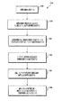
本発明の他の実施態様は、ヒドロゲルマスを使用して、超音波変換器を対象物及び対象物に関連付けられる物理的境界の少なくとも一方と音響的に結合する方法を対象とする。この場合、超音波変換器は、HIFUを対象に適用するように構成される。音響的結合方法は、超音波変換器に電圧を引火するために使用される入力電力レベル及び所要時間を選択するステップと、超音波変換器を対象物及び対象物と関連付けられる物理的境界の少なくとも一方を結合するために使用されるとき、構造的完全性を維持することができるヒドロゲルマスを提供するステップと、選択された入力電力レベルを選択された所要時間使用するステップとを含んでいる。音響的結合方法の他のステップは、ヒドロゲルマスの近位表面を超音波変換器の外表面と結合することと、ヒドロゲルマスの遠位表面の外側限界を、対象物及びヒドロゲルマスの遠位表面から対象物を分離する物理的境界の少なくとも一方と結合することとを含んでいる。 Another embodiment of the present invention is directed to a method of using an hydrogel mass to acoustically couple an ultrasonic transducer with at least one of an object and a physical boundary associated with the object. In this case, the ultrasonic transducer is configured to apply HIFU to the subject. The acoustic coupling method includes the steps of selecting an input power level and duration required to ignite a voltage across the ultrasonic transducer, and at least the physical boundary associated with the object and the object. Providing a hydrogel mass capable of maintaining structural integrity when used to bond one, and using a selected input power level for a selected duration. Other steps of the acoustic coupling method include coupling the proximal surface of the hydrogel mass with the outer surface of the ultrasonic transducer, the outer limit of the distal surface of the hydrogel mass, and the distal surface of the object and hydrogel mass. Coupling to at least one of the physical boundaries separating the object from the object.
結合が完了した後、選択された入力レベルにおいて、選択された所要時間、超音波変換器に電圧を印加するステップが実施され、ヒドロゲルマスは、音響変換器を、対象物及びヒドロゲルマスの遠位表面から対象物を分離する物理的境界の少なくとも一方と音響的に結合する。 After the coupling is complete, a step of applying a voltage to the ultrasonic transducer at a selected input level for a selected duration is performed, and the hydrogel mass moves the acoustic transducer away from the object and the hydrogel mass. Acoustically coupled to at least one of the physical boundaries separating the object from the surface.
追加のステップは、ヒドロゲルマスの遠位表面を対象物の少なくとも1つ及び物理的境界に結合した後、HIFUによってヒドロゲルマスの遠位表面を損傷するのを防止するために、ヒドロゲルマスの遠位表面を水和させること、及び/又は、薬剤を対象物及び物理的境界の少なくとも一方に送り込むことができる。 An additional step is to connect the distal surface of the hydrogel mass to at least one of the objects and the physical boundary, and then prevent the hydrogel mass distal surface from being damaged by the HIFU. The surface can be hydrated and / or the drug can be delivered to at least one of the object and the physical boundary.
少なくとも1つの実施形態では、ヒドロゲルマスを提供するステップは、ヒドロゲルマスの下面と遠位表面との間の長さが、超音波変換器の焦点領域が対象物の近傍に位置することを保証するヒドロゲルマスを選択するステップを含んでいる。 In at least one embodiment, the step of providing the hydrogel mass ensures that the length between the lower surface of the hydrogel mass and the distal surface ensures that the focal region of the ultrasonic transducer is located near the object. Selecting a hydrogel mass.
他の実施形態では、ヒドロゲルマスを提供するステップは、以下の条件:(a)超音波変換器は約1秒から約100秒にわたる期間、電圧を印加される、及び(b)超音波変換器によって生成される音響ビームの強度は、約100W/cm2から約10,000W/cm2の範囲である、の下で、超音波変換器を対象物及び対象物と関連付けられる物理的境界の少なくとも一方と結合するために使用されるとき、ヒドロゲルマスが構造強度を維持するのを可能にするように、十分に高い融点及び十分に低い音響吸収度を有するヒドロゲルマスを選択するステップを含んでいる。 In other embodiments, providing the hydrogel mass comprises the following conditions: (a) the ultrasonic transducer is energized for a period ranging from about 1 second to about 100 seconds; and (b) the ultrasonic transducer. the intensity of the acoustic beam produced by ranges from about 100W / cm 2 to about 10,000 W / cm 2, under, at least the physical boundary associated with the object and the object an ultrasonic transducer Selecting a hydrogel mass having a sufficiently high melting point and a sufficiently low acoustic absorption to allow the hydrogel mass to maintain structural strength when used to bond with one .
ヒドロゲルマスの近位表面を超音波変換器の外表面結合するステップは、ヒドロゲルマスを超音波変換器と取外し式に結合するために保持ハウジングを使用するステップを含むことができる。保持ハウイングは、近位表面及び遠位表面の外側限界を除いて、ヒドロゲルマスの各表面をほぼ包含する。 Bonding the proximal surface of the hydrogel mass to the outer surface of the ultrasonic transducer can include using a retaining housing to removably couple the hydrogel mass with the ultrasonic transducer. The retention howling substantially encompasses each surface of the hydrogel mass except for the outer limits of the proximal and distal surfaces.
本発明の他の実施態様は、HIFUを対象に適用するように構成された超音波変換器と音響的に結合されるように、ヒドロゲルマスを作製する方法を対象とする。この場合、ヒドロゲルマスは、超音波変換器と結合されるように構成される近位表面と、対象物及び対象物を超音波変換器から分離する物理的境界の少なくとも一方と結合されるように構成される遠位表面とを含んでいる。ヒドロゲルマス作製方法は、重合及び水和されたとき、ヒドロゲルマスを形成することができる少なくとも1つのモノマーを提供するステップと、少なくとも1つのモノマーの重合を誘起する薬剤を提供するステップと、重合される少なくとも1つのモノマーの量を水和させるのに十分な量の水を提供するステップと、ヒドロゲルマスを所望のサイズ及び形状に形成するように構成される型を提供するステップとを含んでいる。 Another embodiment of the invention is directed to a method of making a hydrogel mass to be acoustically coupled to an ultrasonic transducer configured to apply a HIFU to the subject. In this case, the hydrogel mass is coupled to a proximal surface configured to be coupled with the ultrasonic transducer and at least one of an object and a physical boundary separating the object from the ultrasonic transducer. A distal surface configured. The method of making a hydrogel mass comprises providing at least one monomer capable of forming a hydrogel mass when polymerized and hydrated, providing an agent that induces polymerization of the at least one monomer, Providing a sufficient amount of water to hydrate the amount of the at least one monomer and providing a mold configured to form the hydrogel mass into a desired size and shape. .
ヒドロゲルマスは、適切な量の各モノマーと、重合を誘起する薬剤と、水とを合わせて混合して、混合物を形成し、混合物を型内に導入して、混合物が型において重合することを可能にすることによって生成される。重合が完了した後、ヒドロゲルマスは、型から取り外される。 Hydrogel mass is a combination of an appropriate amount of each monomer, an agent that induces polymerization, and water mixed together to form a mixture, which is introduced into the mold and allowed to polymerize in the mold. Generated by enabling. After the polymerization is complete, the hydrogel mass is removed from the mold.
少なくとも1つの実施形態では、型は、流体連絡する容器及び型ボリューム(molt volume)を含んでいる。この型ボリュームは、生成されるヒドロゲルマスの所望のサイズ及び形状に合致する。そのような実施形態では、混合物は、型ボリュームが混合物で満たされるまで、容器を経て型内に導入され、追加の混合物は容器にある。容器における混合物の重合は阻止されるが、型ボリュームにおける混合物の重合は可能である。重合は、型ボリュームにおける混合物の容積を低減し、それにより、容器の混合物が型ボリューム内にさらに流れ込み、重合する。型ボリュームが重合ヒドロゲルマスで満たされた後、容器ボリュームの混合物は、重合が可能になる。ヒドロゲルマスは、型から取り外され、ヒドロゲルマスのあらゆる所望されない部分(すなわち、容器に対応する部分)が除去される。 In at least one embodiment, the mold includes a fluid communicating container and a mold volume. This mold volume matches the desired size and shape of the resulting hydrogel mass. In such embodiments, the mixture is introduced into the mold through the container until the mold volume is filled with the mixture, and the additional mixture is in the container. Polymerization of the mixture in the vessel is prevented, but polymerization of the mixture in the mold volume is possible. Polymerization reduces the volume of the mixture in the mold volume so that the container mixture flows further into the mold volume and polymerizes. After the mold volume is filled with the polymerized hydrogel mass, the mixture of container volumes can be polymerized. The hydrogel mass is removed from the mold and any undesired portion of the hydrogel mass (ie, the portion corresponding to the container) is removed.
少なくとも1つの実施形態では、容器における混合物の重合を阻止するステップは、容器の混合物を攪拌するステップを含んでいる。容器は、所望されるヒドロゲルマスの遠位表面に対応する型ボリュームの部分より上に配置されることが好ましい。容器は、遠位表面が凸、平坦、又は凹であるヒドロゲルマスを生成するように成形することができる。 In at least one embodiment, preventing polymerization of the mixture in the container comprises agitating the mixture in the container. The container is preferably positioned above the portion of the mold volume corresponding to the desired distal surface of the hydrogel mass. The container can be shaped to produce a hydrogel mass that has a convex, flat, or concave distal surface.
ヒドロゲルマス作製方法は、ヒドロゲルマスが、事前に確定された条件下において音響変換器を対象に結合するために使用されたとき、構造的完全性を維持することが可能であるように、所望の融点及び所望の音響吸収度を有するヒドロゲルマスを生成するために選択された少なくとも1つのモノマー及び重合を誘起する薬剤を使用することが好ましい。 The hydrogel mass fabrication method is desired so that the hydrogel mass can maintain structural integrity when used to couple an acoustic transducer to a subject under pre-established conditions. It is preferred to use at least one monomer selected to produce a hydrogel mass having a melting point and a desired acoustic absorption and an agent that induces polymerization.
流体チャネルが、生成されるヒドロゲル内に形成されることが好ましい。 Preferably, fluid channels are formed in the resulting hydrogel.
随意選択として、ヒドロゲルマス作製方法は、混合物が型に導入される前に、薬剤を混合物に追加するステップを含むことができ、それにより、生成されるヒドロゲルマスは、薬剤を含んでいる。ヒドロゲルマスが重合した後、薬剤をヒドロゲルマスに追加することができる。 Optionally, the hydrogel mass production method can include adding a drug to the mixture before the mixture is introduced into the mold, whereby the resulting hydrogel mass contains the drug. After the hydrogel mass has polymerized, the drug can be added to the hydrogel mass.
本発明の以上の実施態様及び付随する利点の多くは、添付の図面と関連して取り入れられるとき、以下の詳細な記述を参照することによってより良好に理解される際に、より容易に認識されるであろう。 Many of the foregoing embodiments and attendant advantages of the present invention will be more readily appreciated when better understood by reference to the following detailed description when taken in conjunction with the accompanying drawings. It will be.
以下、図面を参照して本発明の実施態様について説明する。
本発明は、超音波撮像及び具体的にはHIFUに基づく超音波治療である、治療の臨床適用のために、音響結合として固体ヒドロゲルを使用することに関する。本発明の様々な実施態様が、ヒドロゲルに基づく結合体、そのような結合体を使用する結合方法、及びそのような結合体を作製する方法の様々な実施形態に関して開示される。
Embodiments of the present invention will be described below with reference to the drawings.
The present invention relates to the use of solid hydrogels as acoustic coupling for clinical applications of therapy, which is ultrasound imaging and specifically ultrasound therapy based on HIFU. Various embodiments of the present invention are disclosed with respect to various embodiments of hydrogel-based conjugates, methods of joining using such conjugates, and methods of making such conjugates.
本発明を開発する過程で、本発明によるヒドロゲル結合体は、既知の音響変換器を様々な対象に音響的に結合するためにそのようなヒドロゲル結合体を使用することによって評価された。 In the course of developing the present invention, hydrogel conjugates according to the present invention were evaluated by using such hydrogel conjugates to acoustically couple known acoustic transducers to various objects.
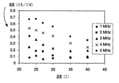
図1は、従来の、HIFUを治療に適用するために使用することができる3.5MHz音響変換器の寸法及びビーム特性を概略的に示す図である。 FIG. 1 schematically illustrates the dimensions and beam characteristics of a conventional 3.5 MHz acoustic transducer that can be used to apply HIFU to therapy.
図1に示すように、使用された特定の音響変換器は、ソニックコンセプツ(Sonic Concepts、ワシントン州ウッディンビル在)から得られる従来の技術のHIFU変換器10(SU−102−01)であった。具体的には凸変換器である単一要素は、3.5MHzの中心周波数を有する。その開口の直径及び曲率半径は、それぞれ、35mm及び55mmであり、1.57のf数を与える。焦点領域のフィールドマッピングは、6dBの焦点幅及びそれぞれ1.0mm及び10.6mmの焦点深度を示した。この音響変換器の基本的なビーム特性も、図1に示されている。 As shown in FIG. 1, the specific acoustic transducer used was a prior art HIFU transducer 10 (SU-102-01) obtained from Sonic Concepts (Woodville, WA). . Specifically, a single element that is a convex transducer has a center frequency of 3.5 MHz. The diameter and radius of curvature of the opening are 35 mm and 55 mm, respectively, giving an f-number of 1.57. The field mapping of the focal region showed a focal width of 6 dB and a focal depth of 1.0 mm and 10.6 mm, respectively. The basic beam characteristics of this acoustic transducer are also shown in FIG.
本発明は、経験的試験において使用された特定の変換器との使用に限定されるものではないことを理解されたい。HIFUの適用に適切な他の音響変換器は、様々な仕様を有することが可能であるが(すなわち、様々な開口直径、様々な曲率、様々なf数、及び様々な焦点領域)、HIFUの適用に適切な多くの音響変換器は、全体的に円錐の形状のビーム12、及びかなりより小さい焦点領域14を呈示する。
It should be understood that the present invention is not limited to use with the particular transducer used in the empirical test. Other acoustic transducers suitable for HIFU applications can have different specifications (ie, different aperture diameters, different curvatures, different f-numbers, and different focal regions), but HIFU's Many acoustic transducers suitable for application present a generally conical shaped
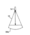
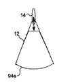
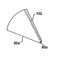
図2Aは、全体的に円錐の形状を有するヒドロゲル結合体を示す図である。ヒドロゲル結合体16の下面20が、超音波変換器と良好に音響接触して容易に結合されるように構成されることが好ましい。結合は、近位表面20の形状が超音波変換器の外表面の形状に対応する場合、最も容易に達成される。しかし、十分な液体又はゲルに基づく結合媒体が、超音波変換器の外表面とヒドロゲル結合体16の近位表面との間に配置される場合、形状の不整合は決定的ではない。多くのHIFU変換器が全体的に円錐の形状のビームを呈示するので、同様の形状を有するヒドロゲル結合体16は、そのような超音波変換器を対象物に結合するのに特によく適している。本発明の開発と関連して実施された経験的な研究では、円錐形のヒドロゲル結合体16に選択された寸法は、図1に示したビームの寸法にほぼ対応する。様々なビーム寸法を有する超音波変換器を結合するように構成されるヒドロゲル結合体を、特定の超音波変換器のビーム寸法にほぼ対応する寸法を有して、同様に生成することができる。
FIG. 2A illustrates a hydrogel conjugate having a generally conical shape. Preferably, the
したがって、ヒドロゲル結合体16は、特定の超音波変換器のビーム寸法にほぼ対応し、ヒドロゲル結合体16の遠位表面18が、超音波変換器の焦点領域内に延びる。ヒドロゲル結合体16の形状は、本発明の各実施態様において、超音波変換器のビーム寸法にほぼ整合する必要はないが、少なくともいくつかの実施形態では、ヒドロゲル結合体16の寸法は、選択された超音波変換器からのビームの寸法にほぼ整合する。以下でより詳細に記述するように、本発明のいくつかの実施態様では、ヒドロゲル結合体16の寸法は、具体的には、特定の目的変換器のビーム寸法とは異なる形状を達成するように操作される。
Thus, the
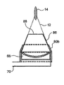
図2Bは、ヒドロゲル結合体が、超音波変換器によって生成されるビームの焦点特徴にほぼ対応することを明瞭に示す図である。超音波変換器10aは、超音波変換器10aがベース15において取り付けられ、一方、ベース15は超音波変換器10aに関しては示されていないという点で、超音波変換器10aとは異なる。当業者なら、超音波変換器10aの上部湾曲表面は、様々なサイズ及び形状のベース15に収容することができることを理解するであろう。超音波変換器10aと共に使用されるベース15は、以下で説明するように、超音波変換器10aを探査子に取り付けるのを容易にする。
FIG. 2B clearly shows that the hydrogel conjugate substantially corresponds to the focal feature of the beam produced by the ultrasonic transducer. The
図2Bでは、ヒドロゲル結合体16は、超音波変換器10aと結合されている。遠位表面18の外側限界は、焦点領域14に隣接して位置する。ヒドロゲル結合体16は、遠位表面18(焦点領域の近傍に位置する)が、患者の組織との音響結合を維持することをできなくさせる融解又は損傷を有さずに、HIFUの適用に耐えるように十分頑強でなければならないことを理解されたい。ヒドロゲル結合体16が、特定の超音波変換器10aのビーム12の寸法とほぼ同様の寸法を有するとき、結合の遠位表面の外側限界又は先端は、焦点領域に近接して位置する。結合のその部分は、撮像変換器を対象に結合するために使用される結合によって経験される温度よりはるかに高い温度に暴露される。したがって、特定の結合材料が、撮像変換器を対象に結合するために許容可能である可能性があるが、同じ材料は、HIFUの適用ではそのような使用に耐えることができない。経験的なデータは、構造上の欠陥が、寒天などの媒体で作成された結合において生じることがあるという結論を支持する。HIFU変換器の焦点領域に隣接する結合の遠位表面の先端又は外側限界における高温は、その位置における遠位表面の亀裂、融解及び構造的完全性の損失をもたらすことがある。したがって、HIFUの適用では、結合として使用される材料を選択するとき、慎重でなければならない。撮像変換器を対象に結合するのに適切な多くの材料は、HIFU変換器を対象に結合する際に遭遇する温度に耐えることができない。
In FIG. 2B, the
本発明の一実施態様は、ヒドロゲル結合体16がHIFUの適用の使用に十分に頑強であることを補償するために、特有のヒドロゲルが選択されるヒドロゲル結合体16を対象とする。選択された材料は、超音波エネルギーを吸収する結果である過熱を回避するために、十分な透過性を有さなければならない。すなわち、結合材料は、可能な限り多くのHIFUエネルギーを焦点領域に送達し、かつエネルギーを吸収しないことが重要である。
One embodiment of the present invention is directed to a
超音波変換器の焦点領域に近接して位置する結合媒体に蓄積するエネルギーは、以下のように計算することができる。 The energy stored in the coupling medium located close to the focal region of the ultrasonic transducer can be calculated as follows:

上式(1)で、Tは時間tより後の温度、T0はHIFUの適用開始時の温度(t=0)、Iは時間平均強度、tは時間、αはネーパー/cmで表された吸収係数、ρは媒体の密度、cmは単位質量あたりの比熱を示している。減衰の大部分(95%を超える)は、吸収に起因し、その結果、吸収は減衰とほぼ同等であると想定される。 In the above equation (1), T is the temperature after time t, T 0 is the temperature at the start of application of HIFU (t = 0), I is the time average intensity, t is time, and α is expressed in naper / cm. The absorption coefficient, ρ is the density of the medium, and cm is the specific heat per unit mass. Most of the attenuation (greater than 95%) is attributed to absorption, so that absorption is assumed to be approximately equivalent to attenuation.
上述した式(1)は、HIFUの焦点の位置が結合剤の先端に近いことを必要とするHIFU装置について、様々な結合材を調査するのに有用である。上式で使用することができる通常の値は、以下の通りである。 Equation (1) above is useful for investigating various binders for HIFU devices that require the HIFU focal point location to be close to the tip of the binder. Typical values that can be used in the above equation are:
・HIFUの強度I、1000W/cm2の大きさ
・HIFUの適用時間t、100秒の大きさ
・密度ρ、1g/mlの大きさ
・単位質量あたりの比熱cm、PAについて6.5J/gの大きさ
・減衰係数α、PAについて3MHzにおいて、0.035Np/cmの大きさ
したがって、上式から決定される温度上昇は、以下の通りである。
HIFU strength I, size of 1000 W / cm 2 HIFU application time t, size of 100 seconds, density ρ, size of 1 g / ml, specific heat per unit mass c m , about 6.5 J / PA Magnitude of g ・ Attenuation coefficient α and PA at 3 MHz, magnitude of 0.035 Np / cm Therefore, the temperature rise determined from the above equation is as follows.
![]()
![]()
この比較的大きい温度上昇は、臨床設定では起きない。相殺パラメータは、HIFU焦点外への熱対流散逸エネルギー及び血流による冷却である。しかし、式は、結合媒体の大きな温度上昇は、焦点において、又は焦点の付近において予測することができることを示す。頑強な結合媒体が、高い融点を有し、ならびに温度上昇を低減する低減衰を有することによって、大きな温度上昇に対処することができなければならない。 This relatively large temperature rise does not occur in a clinical setting. The canceling parameters are heat convection dissipation energy out of the HIFU focus and cooling by blood flow. However, the equation shows that a large temperature rise of the binding medium can be predicted at or near the focus. A robust binding medium must be able to cope with large temperature rises by having a high melting point as well as low damping that reduces the temperature rise.
本発明の第1実施態様によれば、ヒドロゲル結合体16が、あるパラメータに従って音響変換器と関連して使用されるとき、及びヒドロゲル結合体16の一部が、音響変換器の焦点領域に近接して位置する場合、ヒドロゲルマスが構造的完全性を維持するのを可能にするために、結合を形成するヒドロゲルマスが十分に高い融点及び十分に低い音響吸収度を有することを保証するように、ヒドロゲル結合体16を生成するために使用されるヒドロゲルが選択される。パラメータは、以下の通りである:(a)音響変換器は、約1秒から約100秒にわたる期間、電圧を印加される、及び(b)音響変換器によって生成される音響ビームの強度は、約100W/cm2から約10,000W/cm2にわたる。
According to a first embodiment of the invention, when the
経験的試験は、上述した範囲内にあるPAヒドロゲルを生成するために、アクリルアミドモノマーを使用することができると判定した。PAの構造及び特性は、過去30年にわたって徹底的に研究された。現在、PAの最も一般的な生物医学的応用分野は、帯電巨大分子を分離するためのゲル電気泳動である。多くの異なるヒドロゲルが利用であるが、PAヒドロゲルは、上述した範囲内にある特性を有することの他に、他の所望の特性を呈示する。PAヒドロゲルは、重量で70%から90%を超える範囲の非常に高いWCを有することができ、また、室温で比較的容易にかつ迅速に準備することができる。PAヒドロゲルの機械的特性、したがって音響特性は、材料のアクリルアミドモノマーの全体的な濃度を単に変化させることによって、直接的な方式で変更することができる。さらに、PAは、様々な生物医学的応用分野に使用され、多くの研究において、非常に良好な生体親和性を有することが示されている。 Empirical testing has determined that acrylamide monomers can be used to produce PA hydrogels that fall within the ranges described above. The structure and properties of PA have been thoroughly studied over the past 30 years. Currently, the most common biomedical application field for PA is gel electrophoresis to separate charged macromolecules. Although many different hydrogels are available, PA hydrogels exhibit other desirable properties in addition to having properties that are within the ranges described above. PA hydrogels can have very high WC ranging from 70% to over 90% by weight and can be prepared relatively easily and quickly at room temperature. The mechanical properties, and thus the acoustic properties, of the PA hydrogel can be altered in a straightforward manner by simply changing the overall concentration of the acrylamide monomer in the material. Furthermore, PA is used in various biomedical applications and has been shown in many studies to have very good biocompatibility.
血液接触装置の重要な考慮事項は、表面上で血栓症を起こすことに対する耐性である。実験は、PAが血小板付着を呈示しないことを示した。PAに基づく血液ろ過技法の使用を調査した最近の臨床研究は、材料が良好な血液親和性を有することを示し、溶血又は血液凝固の兆候はなかった。中庸な材料コスト及び直接的な製造方法により、安価で、特注の、廃棄可能なHIFU結合装置をPAゲルから作成することが可能になる。 An important consideration of blood contact devices is their resistance to causing thrombosis on the surface. Experiments showed that PA does not exhibit platelet adhesion. Recent clinical studies investigating the use of PA-based blood filtration techniques have shown that the material has good blood affinity, with no signs of hemolysis or blood clotting. Moderate material costs and direct manufacturing methods allow inexpensive, custom made, disposable HIFU binding devices to be made from PA gels.
図3A〜図3Cは、HIFUの適用に適切なヒドロゲル結合体に関する経験的データを得るために製造された3つのPAゲル試験プラグを概略的に示す図である。各サンプルは、2.5cmの直径及び約3cmの高さを有する。剛性及び透明度は、アクリルアミドの濃度と共に増大する。プラグ22aは、10%の濃度のアクリルアミドモノマーを使用して形成され、このプラグの陰影によって示すように、わずかに不透明であることに留意されたい。プラグ22bは、15%の濃度のアクリルアミドモノマーを使用して形成され、プラグ22bの低減された陰影によって示すように、より透明である。プラグ22cは、20%の濃度のアクリルアミドモノマーを使用して形成され、陰影がないことによって示すように、ほぼ透明である。ゲルプラグを生成する手続きについて、以下で詳細に説明する。この手続きは、全体的に円錐形のPAヒドロゲル結合体、ならびに他の形状を有するPAヒドロゲル結合体を生成するためにも使用された。ほぼ透明の結合は、臨床医が、対象領域をより良好に見るために、結合を通して見ることを可能にするという利点を有する。
FIGS. 3A-3C schematically illustrate three PA gel test plugs produced to obtain empirical data on hydrogel conjugates suitable for HIFU applications. Each sample has a diameter of 2.5 cm and a height of about 3 cm. Stiffness and clarity increase with acrylamide concentration. Note that
本発明において使用されるPAゲルを作成するプロセスの概要について、以下に説明する。当業者なら、以下で記述されるプロセスに対する修正を容易に実施することができることを理解するであろう。 An overview of the process for making the PA gel used in the present invention is described below. Those skilled in the art will appreciate that modifications to the process described below can be readily implemented.
合成な3−Dヒドロゲルを形成するために、架橋剤を使用して、長いポリマーチェーンを共に1つの基質において保持する。N,N’−メチレンビス(アクリルアミド)としても知られるビスアクリルアミドが、PAの形成に使用される架橋剤であることが好ましい。ビスアクリルアミド分子は、メチル基によってアミド基において接合された2つのアクリルアミド残留物からなる。2つのアクリルアミド残留物は、2つの独立したモノマーであるかのように、重合反応に関与する。 To form a synthetic 3-D hydrogel, a crosslinker is used to hold the long polymer chain together on one substrate. Bisacrylamide, also known as N, N'-methylenebis (acrylamide), is preferably the crosslinker used to form PA. A bisacrylamide molecule consists of two acrylamide residues joined at the amide group by a methyl group. The two acrylamide residues are involved in the polymerization reaction as if they were two independent monomers.
電気泳動に使用されるPAゲルでは、この緩衝剤は、ゲルのpHをpH8に調整するために使用される。PAゲル電気泳動では、媒体のpHは、使用される生物医学的分子上の電荷を決定する際に重要である。溶液のpHは、アクリルアミドモノマーの−NH2基のプロトン化状態に影響を与える可能性がある。本発明に関して、pHの影響は調査されておらず、単に各ゲルについて一定に維持された。PA電気泳動の生成は周知であるので、本発明において使用されるPAの作成には、同じpHレベルが使用された。使用された緩衝溶液は、トリス(ヒドロキシメチル)アミノメタンとも呼ばれるトリズマ(Trizma)ベース、及びトリス(ヒドロキシメチル)アミノメタン塩酸塩とも呼ばれるトリズマ塩酸塩であった。 In PA gels used for electrophoresis, this buffer is used to adjust the pH of the gel to pH8. In PA gel electrophoresis, the pH of the medium is important in determining the charge on the biomedical molecule used. The pH of the solution can affect the protonation state of the —NH 2 group of the acrylamide monomer. With respect to the present invention, the effect of pH has not been investigated and was simply kept constant for each gel. Since the production of PA electrophoresis is well known, the same pH level was used to make the PA used in the present invention. The buffer solutions used were Trizma base, also called Tris (hydroxymethyl) aminomethane, and Trizma hydrochloride, also called Tris (hydroxymethyl) aminomethane hydrochloride.
アンモミウム過硫酸塩(APS)は、遊離基の源であるので、重合の開始剤として使用された。溶液において、APSは、過硫酸塩イオンS2O8 2−を形成する。この一般的な水溶性開始剤は、既知の最も強力な化学酸化剤の1つである。 Ammonium persulfate (APS) was used as an initiator for the polymerization because it is a source of free radicals. In solution, APS forms the persulfate ion S 2 O 8 2− . This common water soluble initiator is one of the most powerful chemical oxidants known.
N,N,N’,N’−Tテトラメチルエチレンジアミンとしても知られるTEMEDは、基の形成プロセスに触媒作用を及ぼす。APS及びTEMEDは、酸化還元システムを形成し、この場合、APSが酸化剤、TEMEDが還元剤である。過硫酸塩−TEMEDシステムの酸化還元開始機構は、よく理解されていないが、TEMEDは、過硫酸塩遊離基の他に遊離基を形成し、両方の基が、開始プロセスに関与するようである。 TEMED, also known as N, N, N ', N'-T tetramethylethylenediamine, catalyzes the group formation process. APS and TEMED form a redox system, where APS is the oxidizing agent and TEMED is the reducing agent. Although the redox initiation mechanism of the persulfate-TEMED system is not well understood, TEMED forms free radicals in addition to persulfate free radicals, both groups appear to be involved in the initiation process. .
APS−TEMED酸化還元システムは、熱開始剤のタイプである。15%の単位容積重量のPAゲルでは、重合中の最高温度は、約61℃であった。全溶液に対するAPS−TEMED開始剤の割合は、重合が行われる率を決定する。重合率は、開始剤の割合の増大と共に増大する。さらに、反応率及び温度は、溶液のアクリルアミドの濃度と共に増大する。したがって、より高濃度のゲルは、より低濃度のゲルより迅速な率で重合して、より高い温度に達する傾向がある。 The APS-TEMED redox system is a type of thermal initiator. For a 15% unit volume weight PA gel, the maximum temperature during polymerization was about 61 ° C. The ratio of APS-TEMED initiator to total solution determines the rate at which the polymerization takes place. The polymerization rate increases with increasing proportion of initiator. Furthermore, the reaction rate and temperature increase with the concentration of acrylamide in the solution. Thus, higher concentration gels tend to polymerize at a faster rate than lower concentration gels to reach higher temperatures.
PAの物理的特性は、ゲルのアクリルアミドモノマーの濃度に従って変化する。本発明に関する経験的データの収集に使用されるアクリルアミドの濃度は、10%から20%の単位容積重量(w/v)にわたる。パーセント濃度は、全アクリルアミドの質量と重合前溶液の容積との比によって決定された。ゲルを準備するために、19:1のモノマー対架橋剤の比を有する40%w/vアクリルアミドの水溶液(LIQUI−GEL;ICN Biomedicals、オハイオ州オーロラ(Aurora、Ohio)在)が使用された。ヒドロゲルは、上記で留意した遊離基チェーン反応重合プロセスによって溶液において形成された。開始された溶液は、円筒の型(図3A〜図3C参照)、又は以下で記述するほぼ円錐形の型(図7及び図8参照)に移される。円筒の型は、材料の試験及び特徴付け用のプラグを生成するために主に使用され、一方、円錐形の型は、図1に関連して記述した音響変換器で試験されたヒドロゲル結合体を生成するために使用された。円筒の型に関して、型は、ゲルの上面が底面に平行に形成されるように、直立に維持された。各ゲルプラグは、約25分から30分間重合することが可能とされた。結果的な円筒ゲルプラグは、直径が2.5cmで、高さが約3cmであった(図3A〜図3C)。ヒドロゲルを使用することに関連する困難は、ヒドロゲルは、周囲空気に暴露されたままであるとき脱水され、水中に置かれるとき、水の吸収の増大のために膨張することである。したがって、ゲルは、重合後1時間以内に試験されるか、又は、後に使用するために、真空封止されたプラスチックバッグに格納された。 The physical properties of PA vary according to the concentration of acrylamide monomer in the gel. The concentration of acrylamide used to collect empirical data related to the present invention ranges from 10% to 20% unit volume weight (w / v). The percent concentration was determined by the ratio of the total acrylamide mass to the pre-polymerization solution volume. To prepare the gel, an aqueous solution of 40% w / v acrylamide (LIQUI-GEL; ICN Biomedicals, Aurora, Ohio) with a 19: 1 monomer to crosslinker ratio was used. The hydrogel was formed in solution by the free radical chain reaction polymerization process noted above. The initiated solution is transferred to a cylindrical mold (see FIGS. 3A-3C) or a generally conical mold described below (see FIGS. 7 and 8). Cylindrical molds are mainly used to create plugs for material testing and characterization, while conical molds are hydrogel conjugates tested with the acoustic transducer described in connection with FIG. Was used to generate With respect to the cylindrical mold, the mold was kept upright so that the top surface of the gel was formed parallel to the bottom surface. Each gel plug was allowed to polymerize for about 25 to 30 minutes. The resulting cylindrical gel plug was 2.5 cm in diameter and about 3 cm in height (FIGS. 3A-3C). A difficulty associated with using hydrogels is that hydrogels dehydrate when left exposed to ambient air and swell due to increased water absorption when placed in water. Thus, the gel was either tested within 1 hour after polymerization or stored in a vacuum sealed plastic bag for later use.
<バルク特性>
水の含有量(WC)及び密度は、アクリルアミドの濃度を変化させて、ゲルについて測定された。WCは、10%、15%、及び20%w/vのアクリルアミド濃度について決定された。6つのゲルサンプルが、各濃度について試験された。密度は、10%、12,5%、15%、17.5%、及び20%w/Vの濃度について測定された。7つのゲルサンプルが、この濃度について試験された。
<Bulk characteristics>
Water content (WC) and density were measured on the gel with varying concentrations of acrylamide. WC was determined for acrylamide concentrations of 10%, 15%, and 20% w / v. Six gel samples were tested for each concentration. Density was measured for concentrations of 10%, 12.5%, 15%, 17.5%, and 20% w / V. Seven gel samples were tested for this concentration.
WCは、重合直後の水和ゲルの質量mhと脱水ゲルの質量mdとを比較することによって決定された。水の含有量は、以下の式を使用して計算された。 WC was determined by comparing the mass m h of hydrated gel after polymerization and the mass m d dehydration gel. The water content was calculated using the following formula:
様々な濃度におけるPAゲルのバルク特性及び音響特性の測定値を表1に列挙する。 Table 1 lists the measured bulk and acoustic properties of PA gel at various concentrations.
重合直後のゲルの密度ρは、ゲルの質量をその容積で除算することによって計算された。質量は電子スケール(electronic scale)で測定され、容積は水変位技法を使用して測定された。 The density ρ of the gel immediately after polymerization was calculated by dividing the mass of the gel by its volume. Mass was measured on an electronic scale and volume was measured using a water displacement technique.
PAのWCは、増大するアクリルアミド濃度の線形関数として、87%から76%まで減少した。ゲルの密度は、水の密度よりわずかに大きいとことが判明し、増大するアクリルアミド濃度の線形関数として、1.02から1.05g/mlに増大した。 The WC of PA decreased from 87% to 76% as a linear function of increasing acrylamide concentration. The density of the gel was found to be slightly greater than the density of water and increased from 1.02 to 1.05 g / ml as a linear function of increasing acrylamide concentration.
<PAヒドロゲルの音響特性>
音速c(m/s)、音響インピーダンスZ(Mrayl)、及び減衰α(dB/cm)が、10%、12.5%、15%、17.5%、及び20%w/vの5つの異なるアクリルアミド濃度のゲルについて測定された。各濃度について、7つのゲルサンプルが、25℃において試験された。さらに、音響特性が、23℃から45℃にわたる異なる温度において、1つの15%w/vアクリルアミドゲルサンプルについて測定された。
<Acoustic properties of PA hydrogel>
Sound velocity c (m / s), acoustic impedance Z (Mrayl), and attenuation α (dB / cm) are 5% of 10%, 12.5%, 15%, 17.5%, and 20% w / v. Measured on gels with different acrylamide concentrations. For each concentration, 7 gel samples were tested at 25 ° C. In addition, acoustic properties were measured for one 15% w / v acrylamide gel sample at different temperatures ranging from 23 ° C to 45 ° C.
パルス伝送技法を使用して、PAサンプルの減衰係数及び音速を測定した。計算は、2つの音響経路が比較される周知の代入法に基づいていた。サンプル経路は、両側面上に約2センチメートルの水を有するゲルサンプルを包含し、基準経路は、水のみを包含した。減衰係数は、1MHzから5MHzの周波数において測定された。 A PA sample was used to measure the attenuation coefficient and speed of sound of a PA sample. The calculation was based on a well-known substitution method in which two acoustic paths are compared. The sample path included a gel sample with about 2 centimeters of water on both sides and the reference path included only water. The attenuation coefficient was measured at frequencies from 1 MHz to 5 MHz.
試験された濃度範囲では、PAの音響特性は、増大するアクリルアミド濃度の線形関数として増大した。音速は、10%及び20%w/vのゲルについて、それぞれ1546から1595m/sの範囲であった(図4A)。音響インピーダンスは、1.58から1.68Mraylであった(図5A)。減衰は、1MHzにおいて、0.08から0.14dB/cmであった(図6A)。線形回帰は、濃度に関する減衰係数の増大率が、より高い周波数においてより大きいことを示した。減衰係数対周波数のプロットは、減衰が周波数の線形関数ではないことを示した(図6B)。2次多項式がデータによく当てはまるが、データは、水の場合のようには、厳密な周波数2乗依存を示していない。音速及び音響インピーダンスは、温度と共に増大することが示されたが、減衰は、温度と共に減少することが示された(図4B、図5B及び図6C)。 In the concentration range tested, the acoustic properties of PA increased as a linear function of increasing acrylamide concentration. The speed of sound ranged from 1546 to 1595 m / s for 10% and 20% w / v gels, respectively (FIG. 4A). The acoustic impedance was 1.58 to 1.68 Mrayl (FIG. 5A). The attenuation was 0.08 to 0.14 dB / cm at 1 MHz (FIG. 6A). Linear regression showed that the rate of increase of the attenuation coefficient with respect to concentration was greater at higher frequencies. The attenuation coefficient versus frequency plot showed that the attenuation was not a linear function of frequency (FIG. 6B). A quadratic polynomial fits well in the data, but the data does not show a strict frequency square dependence, as in water. The speed of sound and acoustic impedance were shown to increase with temperature, but the attenuation was shown to decrease with temperature (FIGS. 4B, 5B and 6C).
<PAヒドロゲルの熱特性>
PAの熱伝導率k(W/m/℃)及び比熱容量Cp(J/kg/℃)は、熱インパルスの熱散逸を監視することによって測定された。ニッケル−クロミウム加熱ワイヤが、特注の測定セルの中心を通ってぴんと張られた。開始されたPA溶液は、測定セルに注ぎ込まれ(近似的に5cmの縁を有する立方体)、ヒドロゲルに重合することが可能とされた。4つの針のT型熱電対(オメガエンジニアリングインク(Omega Engineering Inc.コネチカット州スタンフォード在))が、加熱ワイヤに平行にゲルに挿入された。熱電対は、4mmから11mmにわたって、ワイヤから異なる径方向距離に配置された。接合部から加熱ワイヤまでの正確な距離は、超音波撮像システム(ATLコープ(ATL Corp.ワシントン州ボゼル在)のモデルHDI1000(商標))を使用して測定された。LabVIEWTM(ナショナルインストルメンツ(National Instruments、テキサス州オースティン在))プログラムが、加熱ワイヤに送達される電流パルスの長さを制御して、時間の経過に伴う4つの熱電対の温度を記録した。
<Thermal properties of PA hydrogel>
The thermal conductivity k (W / m / ° C.) and specific heat capacity Cp (J / kg / ° C.) of PA were measured by monitoring the heat dissipation of the thermal impulse. A nickel-chromium heating wire was tensioned through the center of a custom measurement cell. The initiated PA solution was poured into a measuring cell (a cube with an approximate 5 cm edge) and allowed to polymerize into a hydrogel. Four needle T-type thermocouples (Omega Engineering Inc., Stamford, Conn.) Were inserted into the gel parallel to the heating wire. Thermocouples were placed at different radial distances from the wire, ranging from 4 mm to 11 mm. The exact distance from the junction to the heating wire was measured using an ultrasound imaging system (Model HDI1000 ™ from ATL Corp (ATL Corp., Bozel, WA)). The LabVIEW ™ (National Instruments, Austin, Texas) program controlled the length of the current pulse delivered to the heating wire and recorded the temperature of the four thermocouples over time.
以下の式(3)は、円筒座標における伝熱のフーリエの法則に基づいており、加熱後のある時間における径方向の温度分布を決定するために使用された。 Equation (3) below is based on Fourier's law of heat transfer in cylindrical coordinates and was used to determine the radial temperature distribution at some time after heating.
上式(3)で、T(℃)はワイヤからのある径方向距離r(m)における周囲からの温度上昇、t(s)は測定が行われた加熱後の時間、Q(J)は分配された熱全体(J)、L(m)はワイヤの長さ、ρ(kg/m3)はゲルの密度、及びχ(m2/s)はゲルの熱拡散率であった。この式は、測定までの時間が加熱時間より著しく長く、かつワイヤの直径が無視できることを想定している。 In the above equation (3), T (° C.) is the temperature rise from the periphery at a certain radial distance r (m) from the wire, t (s) is the time after heating when the measurement was performed, and Q (J) Total heat distributed (J), L (m) was wire length, ρ (kg / m 3 ) was gel density, and χ (m 2 / s) was gel thermal diffusivity. This equation assumes that the time to measurement is significantly longer than the heating time and that the wire diameter is negligible.
熱特性が、10%、15%、及び20%w/vの3つの異なるアクリルアミド濃度について測定された。熱は5s間加えられ、これにより、ワイから4mmにおいて、温度が約1℃上昇した。Ln(Tt)対r2/tが、4つの熱電対の位置のそれぞれについてグラフ化された。線をデータに当てはめることによって、傾斜及び切片を使用して、Cp及びkを計算した。2つの独立した実験が、各アクリルアミド濃度について実施された。 Thermal properties were measured for three different acrylamide concentrations of 10%, 15%, and 20% w / v. Heat was applied for 5 s, which caused the temperature to rise about 1 ° C. at 4 mm from the wai. Ln (Tt) vs. r 2 / t was graphed for each of the four thermocouple positions. By fitting a line to the data, by using the slope and intercept were calculated C p and k. Two independent experiments were performed for each acrylamide concentration.
熱伝導率及び比熱容量は、試験された範囲にわたってアクリルアミドの濃度に関して計測される程度には変化しなかった。PAの全体的な平均熱伝導率0.84W/m/℃及び比熱容量6470J/kg/℃は、水の対応する値0.61W/m/℃及び4178J/kg/℃よりわずかに大きいことが判明した。 Thermal conductivity and specific heat capacity did not change as measured for acrylamide concentration over the range tested. The overall average thermal conductivity 0.84 W / m / ° C. and specific heat capacity 6470 J / kg / ° C. of PA may be slightly larger than the corresponding values of water 0.61 W / m / ° C. and 4178 J / kg / ° C. found.
<電力効率>
電力効率が、集束音波を水に送達する際のPAカプラの有効性を判定するために測定された。変換器カプラ装置の全体的な電力効率EOverallが、水バスに送達される出力音響電力と変換器に供給される入力電力との比として確定された。EOverallは、以下のように確定された。
<Power efficiency>
Power efficiency was measured to determine the effectiveness of the PA coupler in delivering focused sound waves to water. The overall power efficiency EOverall of the transducer coupler device was established as the ratio of the output acoustic power delivered to the water bus and the input power supplied to the transducer. EOverall was determined as follows.
EOverall=ETransducer×ECoupler (4) EOverall = ETransducer × ECoupler (4)
上式(4)で、ETransducerは変換器の効率であり、Eouplerはカプラの効率であった。ETransducerは、カプラがまったく取り付けられていない変換器の出力された音響出力を測定することによって決定された。次いで、カプラの効率を式3から計算することができた。アクリルアミドの濃度が装置の出力効率にどのような影響を与えるかを決定するために、試験が実施された。比較のために、完全長のゲルカプラと同じ寸法を有する水充填結合円錐も試験された。カプラは、3.5MHzHIFU変換器に取り付けられた。放射力反射天秤(オーミックインストルメンツコ(Ohmic Instruments Co.メリーランド州イーストン在))を使用して、2Wから90Wにわたる5つの入力電力レベルについて出力音響電力を測定した。出力電力が、入力電量に対してプロットされ、全効率が、データに対する最適当てはめ線の傾斜として計算された。効率が、10%、15%、及び20%のアクリルアミド濃度を有する完全長凸先端ゲルカプラについて測定された。これらのデータは、ゲルにおける減衰に基づく理論上の効率と比較された。ゲルの理論的な効率ECouler Theoryは、以下の式を使用して計算された。
In the above equation (4), E Transducer is efficient converter, E oupler was efficient coupler. The E Transducer was determined by measuring the output acoustic power of a transducer with no coupler attached. The coupler efficiency could then be calculated from
ECoupler・Theory=exp(−2αd) (5) E Coupler Theory = exp (-2αd) (5)
上式(5)で、α’(ネーパー/cm)は、3.5MHzにおいて測定されたゲルの減衰係数、d(5.2cm)は、ゲルの長さであった。この計算では、音響電力の損失は、ゲルカプラにおける減衰のみのためであると想定された。水による減衰は無視できると想定された。 In the above equation (5), α ′ (Naper / cm) is the gel attenuation coefficient measured at 3.5 MHz, and d (5.2 cm) is the gel length. In this calculation, it was assumed that the loss of acoustic power was only due to attenuation in the gel coupler. Water attenuation was assumed to be negligible.
表2は、異なるカプラの測定された電力効率及び理論的な電力効率を列挙する。変換器の効率は、55.8%において測定された。5.2cmのゲル円錐を変換器に取り付けることにより、全効率は、20%及び10%のアクリルアミド濃度について、それぞれ22.4%と28.6%との間に降下した。変換器効率に対する全効率を正規化することにより、ゲル円錐は、40.1%から51.3%のカプラ効率を有することが示された。比較のために、水充填円錐のカプラ効率が、65.3%において測定された。ゲル円錐の測定されたカプラ効率は、計算された理論上の効率より14%から23%小さい。3.5MHzにおいてPAについて使用された減衰係数は、測定減衰データに当てはめられた多項式から計算され、10%、15%、及び20%のアクリルアミドについて、それぞれ、0.029、0.046、及び0.059ネーパー/cmであることが判明した。 Table 2 lists the measured and theoretical power efficiency of the different couplers. The efficiency of the transducer was measured at 55.8%. By attaching a 5.2 cm gel cone to the transducer, the overall efficiency dropped between 22.4% and 28.6% for 20% and 10% acrylamide concentrations, respectively. By normalizing the total efficiency relative to the converter efficiency, the gel cone was shown to have a coupler efficiency of 40.1% to 51.3%. For comparison, the coupler efficiency of a water filled cone was measured at 65.3%. The measured coupler efficiency of the gel cone is 14% to 23% less than the calculated theoretical efficiency. The attenuation coefficient used for the PA at 3.5 MHz was calculated from the polynomial fitted to the measured attenuation data and was 0.029, 0.046, and 0 for 10%, 15%, and 20% acrylamide, respectively. 059 naper / cm.
<PAヒドロゲル結合体の有益な特性>
PAの有益な音響特性により、材料は、超音波治療及び超音波診断の両方の適用について良好な結合媒体となる。ゲルは、ほとんど水からなる同質材料である。これは、低減衰を有し、音速及び音響インピーダンスは、組織の音速及び音響インピーダンスと同様である。ゲルの理想的なインピーダンスのために、最小限の反射が、ゲル組織境界において起きる。PA結合の利点は、その音響特性が、アクリルアミドの濃度と共に線形に変化することである。したがって、材料の音響特性は、ゲルの濃度が既知である場合、直線的なプロセスであり、患者の身体における特有の組織のインピーダンスと整合させることを比較的容易にする。
<Useful properties of PA hydrogel conjugate>
The beneficial acoustic properties of PA make the material a good binding medium for both ultrasound treatment and ultrasound diagnostic applications. Gel is a homogeneous material consisting mostly of water. It has low attenuation, and the sound speed and acoustic impedance are similar to the sound speed and acoustic impedance of tissue. Due to the ideal impedance of the gel, minimal reflection occurs at the gel tissue boundary. The advantage of PA binding is that its acoustic properties change linearly with acrylamide concentration. Thus, the acoustic properties of the material are a linear process where the concentration of the gel is known, making it relatively easy to match the specific tissue impedance in the patient's body.
PAカプラは、HIFUの適用に所望されるものとするいくつかの特性を有する。音響特性は、アクリルアミドの濃度と共に線形に変化し、これは、ゲルの音響及びインピーダンス特性の直接的な修正を見込む。PAカプラの音響インピーダンスは、単にアクリルアミドの濃度を変化させることによって、特定の組織に整合させることができる。経皮的なHIFUの適用では、ゲル組織境界におけるインピーダンス不整合を低減することにより、反射波及び定常波によって生じる皮膚火傷の発生を減少させることができる。PAの音速を特定の組織タイプに整合させることにより、ゲル組織境界において超音波ビームの反射によって生じる悪影響を低減することができる。いくつかのHIFUの適用では、焦点の位置が変位することにより、回りの正常な組織に所望されない損傷が起きることがあるので、この問題は、特に重要である可能性がある。 PA couplers have several characteristics that make them desirable for HIFU applications. The acoustic properties vary linearly with the concentration of acrylamide, which allows for a direct modification of the acoustic and impedance properties of the gel. The acoustic impedance of the PA coupler can be matched to a specific tissue simply by changing the concentration of acrylamide. In percutaneous HIFU applications, the occurrence of skin burns caused by reflected and standing waves can be reduced by reducing impedance mismatch at the gel tissue boundary. By matching the speed of sound of the PA to a specific tissue type, adverse effects caused by reflection of the ultrasonic beam at the gel tissue boundary can be reduced. In some HIFU applications, this problem can be particularly important because the focal position displacement can cause undesired damage to surrounding normal tissue.
低減衰のために、PA結合は、許容可能な電力伝達効率を有する。効率は、カプラの長さが増大すると共に減少するので、表面的なHIFU処置では、焦点距離の短い変換器を使用することが有利である可能性がある。 Due to the low attenuation, the PA coupling has an acceptable power transfer efficiency. Since efficiency decreases with increasing coupler length, it may be advantageous to use a short focal length transducer for superficial HIFU treatment.
<ヒドロゲル結合体の有益な特性>
ヒドロゲルは、一般に、固体結合材料であることに関連する利点を有する。水充填カプラとは異なり、ヒドロゲル結合媒体の包含及び漏れに関しては問題がない。適切な型を使用して、特定のHIFU変換器に適合するように、結合を形成することができる。形状及びサイズも、特定の応用分野について修正することができる。表皮的な適用では、組織境界より下の焦点深度は、以下で詳細に記述するように、様々な長さを有する結合を使用することによって調節することができる。外科的な止血の応用分野では、円錐先端の形状及び高さは、より有効な処置を達成するように変更することができる。先端の形状の修正は、以下で記述するように、適切な型を選択することによって行われる。
<Useful properties of hydrogel conjugate>
Hydrogels generally have the advantages associated with being a solid binding material. Unlike water-filled couplers, there are no problems with the inclusion and leakage of hydrogel binding media. An appropriate type can be used to form a bond to suit a particular HIFU transducer. The shape and size can also be modified for specific applications. For epidermal applications, the depth of focus below the tissue boundary can be adjusted by using bonds with various lengths, as described in detail below. In surgical hemostasis applications, the shape and height of the cone tip can be varied to achieve a more effective procedure. The tip shape modification is done by selecting the appropriate mold, as described below.
ヒドロゲル結合体は、HIFU変換器に永続的に取り付けられる必要はない。エポキシによってPZT要素に保持されていた従来の技術のアルミニウムカプラとは異なり、ヒドロゲル結合体は、水又はソノグラフィゲルの薄層で一次的に取り付けて、異なるヒドロゲル結合体と容易に交換することができる。ヒドロゲル結合体の廃棄可能な性質は、焦点がヒドロゲル結合体の遠位先端の付近にあるHIFUの適用に理想的である。ゲルが、先端に対するHIFU又は機械に関係するある程度の損傷を最終的に保持する可能性があるが、新しいヒドロゲル結合体が現在のヒドロゲル結合体と容易に置き換わることができるので、この損傷は、その後の使用について変換器を永続的に損なうことはない。 The hydrogel conjugate need not be permanently attached to the HIFU transducer. Unlike prior art aluminum couplers held on PZT elements by epoxy, hydrogel conjugates can be attached primarily with a thin layer of water or sonographic gel and easily exchanged with different hydrogel conjugates. it can. The disposable nature of the hydrogel conjugate is ideal for HIFU applications where the focal point is near the distal tip of the hydrogel conjugate. Although the gel may eventually retain some damage related to the HIFU or machine to the tip, this damage will then be reduced because the new hydrogel conjugate can easily replace the current hydrogel conjugate. There is no permanent damage to the converter with respect to its use.
PAヒドロゲルは、経験的に試験され、HIFUの適用に使用されることができることが実証されたが、他のヒドロゲル材料又は異なるヒドロゲルの混合物が、HIFUを適用するためのカプラとして使用されるのに十分頑強であると識別されることが予期される。たとえば、ポリ(2−ヒドロキシルエチルメタクリレート)、又はpHEMAは、HIFUの適用に有用なヒドロゲルである可能性が高い。 Although PA hydrogels have been empirically tested and demonstrated that they can be used for HIFU applications, other hydrogel materials or mixtures of different hydrogels can be used as couplers for applying HIFU. It is expected to be identified as robust enough. For example, poly (2-hydroxylethyl methacrylate), or pHEMA is likely a useful hydrogel for HIFU applications.
上述した機能試験は、図1に関連して記述した変換器に適合するように設計された円錐PA結合に対して実施された(5.5cm焦点距離及び3.5cm開口直径を有する3.5MHz球状凸単一要素HIFU変換器)。そのような円錐形の結合は、図7及び図8に示す特注の3部分型30を使用して生成された。ゲル円錐は、変換器の曲率に整合する球状凸ベースを有していた。完全長又は切頭の円錐プラスチックハウジングが、ゲルカプラを変換器に保持した。完全長の平坦先端円錐は、4.9cmの長さであり、HIFUの焦点の中心を先端から0.6cmに置いた。先端の形状及び高さは、先端から異なる距離に焦点を置くように変更することができる。大部分の試験では、高さが0.3cmの凸状の先端が使用され、HIFUの焦点の中心を先端から約0.3cmに置いた。
The functional tests described above were performed on a conical PA coupling designed to fit the transducer described in connection with FIG. 1 (3.5 MHz with 5.5 cm focal length and 3.5 cm aperture diameter). Spherical convex single element HIFU transducer). Such a conical bond was generated using a custom three-
図7及び図8を再び参照すると、3部分型は、ベース部分32、中央部分34、及び上部部分36を含む。ベース部分32は、変換器の凹外表面に整合するように構成され、したがって凸表面40を含む。ベース部分32は、異なる形状又は寸法を有する遠位表面を有する異なる変換器についてヒドロゲル結合体を生成するように構成される型を達成するように修正することができる。型30によって生成されるヒドロゲル結合体の近位表面は、ヒドロゲルマスが共に使用される変換器の外表面の形状に対応する。図7は、ベース部分32にあるヒドロゲル結合体38を示す。
Referring again to FIGS. 7 and 8, the three-part mold includes a
中央部分34は、図1及び図2Bに示すように、上述した例示的な変換器の集束特性に整合するように、ほぼ円錐の形状である。当然、所望に応じて、他の形状を使用することができる。上部部分36は、先端成型部分42を含む。これは、以下で詳細に説明するように、型30を使用して生成されるヒドロゲル結合体の遠位表面の外側限界又は先端について、所望の形状を達成するように修正することができる。上部部分36は、容器46を型ボリューム48と流体連絡して結合するドリップチャネル44を含む。型ボリューム48は、ベース部分32、中央部分34、及び上部部分36によって形成される。
The
容器46の機能を、図9A〜図9Cに示す。図9Aでは、液体混合物(上述したアクリルアミドモノマーに基づく混合物など)が、型30の容器46内に導入される。図9Bでは、型ボリューム内の混合物は、重合することが可能であるが、容器の混合物の重合は阻止される。重合を防止する例示的な技法は、容器における攪拌又はかき混ぜである。ポリマーの分野の当業者なら、容器における混合を阻止する他の技法が適切である可能性があることを理解するであろう。例えば、いくつかのポリマー反応は、適切な波長の光で照明することによって開始される(水銀アマルガムを交換するために使用される歯科用ポリマーが一例である)。したがって、重合の阻止は、光が型ボリュームの混合物に加えられる間、その波長の光が容器の混合物に到達することを防止することを含む可能性がある。上記で詳細に記述したPAヒドロゲルは、例示的なヒドロゲルを表すが、型30及び型30の変形形態を使用して、他のヒドロゲルを音響結合に形成することができ、したがって、容器における重合を阻止する技法は、特有の反応及び使用される材料において重合を誘起するために使用される開始剤によって命令されることになることに留意されたい。
The function of the
ヒドロゲルは、重合する際に収縮する。図9Bに示す固体部分は、型ボリュームに導入された当初の混合物を表す。追加の混合物が型ボリューム内に導入されない場合、最終ヒドロゲルの形状は、所望通りではない(すなわち、上端50が失われる)。しかし、型ボリューム内に当初導入された混合物が重合し、収縮する際に、容器からの追加の液体混合物が、型ボリュームに流れ込み、重合する。 Hydrogels shrink when polymerized. The solid portion shown in FIG. 9B represents the original mixture introduced into the mold volume. If no additional mixture is introduced into the mold volume, the shape of the final hydrogel is not as desired (ie, the top 50 is lost). However, as the mixture initially introduced into the mold volume polymerizes and shrinks, additional liquid mixture from the container flows into the mold volume and polymerizes.
型ボリュームが重合混合物(すなわち、ヒドロゲル)で満たされた後、容器の混合物は、重合が可能になる。型は取り外され、容器内(及び容器を型ボリュームに結合するドリップチャネルの内)のヒドロゲルの部分をトリミングすることができる。 After the mold volume is filled with the polymerization mixture (ie, hydrogel), the container mixture is allowed to polymerize. The mold can be removed and the portion of the hydrogel within the container (and within the drip channel connecting the container to the mold volume) can be trimmed.
型30は、実験目的では見事に実施されたが、ヒドロゲル結合体の大量生産は、高速生産に特別に適合された型を使用して達成される可能性が高いことに留意されたい。明らかに、本発明は、具体的には型30を使用する製造、又はさらには3部分型に限定されるものではない。
It should be noted that although
図10A〜図11Dは、上部部分36を修正することにより、様々な構成の遠位表面を有するヒドロゲル結合体を達成することを可能にすることができる方式に関する詳細を提供する。対象物又は対象物と変換器との間に位置する境界との良好な結合を達成するために、ヒドロゲル結合体の遠位表面は、対象物又は境界の表面にそれぞれ密接に合致すべきである。結合ゲルを使用して、あらゆるギャップを埋めることができるが、密接に整合された表面は、結合及び使用の容易さを改善する。
FIGS. 10A-11D provide details regarding the manner in which the
図10A及び図10Bでは、上部部分36は、外側リング36a及び内側部分36bを備える。内側部分36bは、上述した容器及びドリップチャネルを含む(図を簡単にするために、参照符合は省略されている、図8参照)。表面54aが、生成されるヒドロゲル結合体の遠位表面の先端の形状を決定する。
10A and 10B, the
具体的には図示されていないが、リング36a及び中央部分34は、領域62においてスレッドを使用して、回転式に共に結合することができる。リング36a及び中央部分34の寸法は、PA材料の成型中に型が離れないように十分きつくであるが、型の使用後に型を解体するためにリングを取り外すことができるように十分ゆるく、リング36aが中央部分34の上にプレスばめされるように、領域62において構成することができる。また、図10Bに示すようにリング36a及び内側部分36bは、内側部分36bを適切な位置に確実に保持することを可能にするために、領域64においてノッチングされることに留意されたい。
Although not specifically shown,
図11A〜図11Dは、様々な形状の内側部分、及びその内側部分を使用して達成されるヒドロゲル結合体の遠位表面の先端を示す。図11Aでは、内側部分36bは、内側部分36bの底面の完全な凹表面54aに対応して、完全な凸である遠位表面54bの上に先端を有するヒドロゲル結合体を生成するために使用することができる。表面54aの有用な曲率半径は、約4.8mmである。
FIGS. 11A-11D show various shaped inner portions and distal tips of the hydrogel conjugate achieved using the inner portions. In FIG. 11A, the
図11Bでは、内側部分36cは、内側部分36cの底面の短い凹表面54aに合致して、短い凸である遠位表面56bの上に先端を有するヒドロゲル結合体を生成するために使用することができる。凸表面56aの有用な曲率半径は、7.3mmである。
In FIG. 11B, the
図11Cでは、内側部分36dは、平坦58aに合致して、平坦である遠位表面58bの上に先端を有するヒドロゲル結合体を生成するために使用することができ、一方、図11Dでは、内側部分36eは、凸表面60aに合致して、凹である遠位表面60bの上に先端を有するヒドロゲル結合体を生成するために使用することができる。凸表面60aの有用な曲率半径は、7.3mmである。
In FIG. 11C, the
上述した曲率の寸法は、例示を意図しており、本発明を限定するものではないことを理解されたい。当然、あらゆる所望のヒドロゲル結合体の形状を達成するために、型について他の形状を使用することができる。 It should be understood that the curvature dimensions described above are intended to be illustrative and not limiting of the present invention. Of course, other shapes for the mold can be used to achieve any desired hydrogel conjugate shape.
図12Aは、本発明によるヒドロゲル結合体の例示的な使用を示す図である。探査子65では、円錐ヒドロゲル結合体66が、ハンドル70に取り付けられた音響変換器68に添付される。リード72が、音響変換器を電源74に結合する。図12Bでは、探査子65は、患者の皮膚層76に近接する対象にHIFUを適用するために使用されている(そうでない場合は図示せず)。焦点領域14が、皮膚層に近接する(皮膚層内にある)。そのような構成では、結合66の遠位表面は、音響変換器の焦点領域に近接して位置する。したがって、ヒドロゲルが、HIFU治療の適用中、構造的完全性を維持するように十分頑強であることが重要である。探査子65は、患者の体内において使用して、身体の空洞又は切開により挿入することができ、外面的な使用に限定されないことを理解されたい。探査子65の重要性は、ヒドロゲル結合体66の先端が処置部位に直接隣接するように、音響変換器の焦点距離が、ヒドロゲル結合体66の遠位表面に近接して位置することである。したがって、HIFUは、ヒドロゲル結合体66の遠位表面の先端を観測することによって、容易に照準することができる。
FIG. 12A illustrates an exemplary use of a hydrogel conjugate according to the present invention. In the
図12Cに示す探査子65aは、ヒドロゲル結合66aの遠位表面が、音響変換器の焦点領域に直接隣接して、又はそれに近接して位置しないという点で異なる。ヒドロゲル結合体66aは、ヒドロゲル結合体66aの先端が患者の皮膚層に接して位置するとき、音響変換器の焦点領域が、皮下対象78内にあるように、著しくより短い。さらにより短いヒドロゲル結合体を選択することにより、焦点領域が、皮膚層のさらに下にある皮下対象内により深く貫通することが可能になり、一方、より長いヒドロゲル結合体を選択することにより、焦点領域は、皮膚層により近くなる。したがって、対象物の位置が既知である場合、音響変換器の収束領域が所望の対象物に近接して位置することを保証するように、適切な長さのヒドロゲル結合体を選択することができる。より短いヒドロゲル結合体が使用されるとき、頑強性の劣るヒドロゲルを使用することができるが、その理由は、遠位表面が、最高温度に遭遇する可能性が高い焦点領域にもはや近接していないからである。
The probe 65a shown in FIG. 12C differs in that the distal surface of the
図13A〜図13Cは、制約ハウジングを使用して、ヒドロゲル結合を変換器に取外し式に固定することができる方式を示す図である。図13Aは、制約ハウジング80aをヒドロゲル結合体66の上にはめ込む様子を示す分解図である。図13Bでは、制約ハウジング80aは、変換器68(又はハンドル70)に固定されており、それにより、ヒドロゲル結合66を適所に取り付ける。制約ハウジング80aは、円錐端部において開いており、それにより、ヒドロゲル結合体66の遠位表面82の先端が暴露されて、制約ハウジング80aを超えて延びる。図13Cは、電圧を印加されており、音波84をもたらす変換器68を示す図である。変換器の焦点領域は、ヒドロゲル結合体66の遠位表面82の上部限界に近接することに留意されたい。
13A-13C illustrate a manner in which a constraining housing can be used to removably secure a hydrogel bond to a transducer. FIG. 13A is an exploded view showing how the constraining
図14A及び図14Bは、より短いヒドロゲル結合体86を同じ変換器に結合するために使用されているより短い制約ハウジング80bを示す図である。図14Aは、制約ハウジング80bをヒドロゲル結合体86の上にはめ込む方式を示す分解図であり、一方、図14Bは、組み立て図である。図14Bは、ビーム寸法12及び焦点領域14をも含み、ヒドロゲル結合体86の遠位表面88が、焦点領域に近接して位置しないことを示す図である。
14A and 14B show a shorter constraining
図15A〜図15Gは、焦点領域が対象に隣接して位置することを可能にするように、ヒドロゲル結合体の長さを選択することができる方式を示す図である。図15Aでは、ヒドロゲル結合体90が、変換器68の上に位置して示されている。ヒドロゲル結合体90は、長さ92を有する。それぞれが異なる長さを有する複数のヒドロゲル結合体94a〜94fを提供することによって、ヒドロゲル結合体の遠位表面に対する焦点領域の位置を変更することができる。より長いヒドロゲル結合体(たとえば、ヒドロゲル結合94e)は、焦点領域により近く位置する結合の遠位表面をもたらす。より短いヒドロゲル結合体(たとえば、ヒドロゲル結合体94a)は、焦点領域からさらに遠く位置するヒドロゲル結合体の遠位表面をもたらす。図12Cに示すように、結合が短くなると、焦点領域は、結合の遠位表面からより遠くなり、介在組織の表面と接触するようになる。
FIGS. 15A-15G illustrate a manner in which the length of the hydrogel conjugate can be selected to allow the focal region to be located adjacent to the object. In FIG. 15A, the
図16は、可変長のヒドロゲル結合体を使用して得られるシュリーレン画像を示す図である。ヒドロゲルカプラが添付されているHIFU変換器から放出される超音波場を視覚化して、ゲルカプラが何らかの方式でHIFU場をゆがめているかを判定するために、シュリーレン撮像が使用された。2cmの切頭円錐、3cmの切頭円錐、平坦先端を有する完全長の円錐、及び凸型の丸い先端を有する完全長のゲル円錐の形状の異なる4つの15%ゲル円錐が試験された。光の照準ビームが、脱気された水を包含する随意選択の透光性タンクを通過した。HIFUビームは、光ビームの軸と垂直の水タンク内に向けられた。タンクを出る光は、集束及びろ過され、画像は、スクリーンに表示された。 FIG. 16 shows a schlieren image obtained using a variable length hydrogel conjugate. Schlieren imaging was used to visualize the ultrasound field emitted from a HIFU transducer with attached hydrogel coupler to determine if the gel coupler distorts the HIFU field in any way. Four 15% gel cones with different shapes of 2 cm truncated cone, 3 cm truncated cone, full length cone with flat tip, and full length gel cone with convex round tip were tested. The aiming beam of light passed through an optional translucent tank containing degassed water. The HIFU beam was directed into a water tank perpendicular to the axis of the light beam. The light exiting the tank was focused and filtered and the image was displayed on the screen.
得られた画像は、HIFU場が、様々なゲルカプラの存在によって本質的には影響を受けないことを示した。完全長の平坦及び丸い先端のカプラでは、超音波場の画像は、カプラ先端の影ににじみ出ているように見えた。この効果は、おそらくは光ビームの回折によって生じた。 The resulting image showed that the HIFU field was essentially unaffected by the presence of various gel couplers. With a full length flat and rounded tip coupler, the ultrasound field image appeared to ooze out in the shadow of the coupler tip. This effect was probably caused by diffraction of the light beam.
上述したように、具体的にはHIFUの適用において、ヒドロゲル結合体の遠位表面が焦点領域に近接して位置するとき、強度の温度及び圧力により、ヒドロゲル結合体の遠位表面が損傷されることがある。ヒドロゲル結合体は、重量で多量の水を含むので、そのような温度及び圧力は、遠位表面を乾燥させて、表面を損傷することになることが経験的に示されている。したがって、本発明の実施態様は、ヒドロゲル結合体の遠位表面を水和させる(又はヒドロゲル結合体の水和を維持する)手段を組み込む。 As noted above, particularly in HIFU applications, when the hydrogel conjugate distal surface is located proximate to the focal region, intense temperature and pressure damage the hydrogel conjugate distal surface. Sometimes. Since hydrogel conjugates contain a large amount of water by weight, it has been empirically shown that such temperature and pressure will dry the distal surface and damage the surface. Accordingly, embodiments of the present invention incorporate means for hydrating the distal surface of the hydrogel conjugate (or maintaining hydration of the hydrogel conjugate).
図17A〜図17Cは、そのような水和を達成するために使用することができるいくつかの構造を示す図である。図17Aでは、流体チャネル98が水供給(図示せず)と結合され、流体チャネルの他端は、ヒドロゲル結合体96の遠位表面の先端95に隣接して位置する。図17Bでは、流体チャネル98aが、制約ハウジング100に添付され、水供給(図示せず)と結合される。流体チャネルの他端は、ヒドロゲル結合体96の遠位表面の先端95に隣接して位置する。図17Cに示す実施形態では、流体チャネル102が、ヒドロゲル結合体96a内に配置される。流体チャネル102は、水供給(図示せず)と結合され、流体チャネルの他端は、表面が水和するのを可能にするように、ヒドロゲル結合体96aの遠位表面の先端95aに隣接して位置する。
FIGS. 17A-17C illustrate several structures that can be used to achieve such hydration. In FIG. 17A, a
ヒドロゲルを使用する固有の利点は、抗生物質などの薬剤をヒドロゲル結合体内に導入して、ヒドロゲル結合体が患者の組織に接触するところにそのような薬剤を投与することが可能であることである。手術中、ヒドロゲルカプラを使用して、超音波の他に、抗生物質を処置部位内に移送することができる。 An inherent advantage of using hydrogels is that drugs such as antibiotics can be introduced into the hydrogel conjugate, and such drugs can be administered where the hydrogel conjugate contacts the patient's tissue. . During surgery, hydrogel couplers can be used to transfer antibiotics in addition to ultrasound into the treatment site.
図18A〜図18Cは、そのような投薬を達成するために使用することができる構造を示す図である。図18Aでは、ヒドロゲル結合体96bが、ヒドロゲル全体に分布した薬剤104を有する。薬剤は、ヒドロゲルが生成された後に追加することができる。ヒドロゲルは、そのような薬剤を吸収及び格納することができる多くのチャネルをヒドロゲル内に含む。重合が薬剤にとって有害ではない場合、ヒドロゲルが生成される前に薬剤を追加することができることが予期される。図18Bでは、ヒドロゲルに結合された変換器に電圧を印加することにより、いくらかの薬剤が、ヒドロゲル結合体の遠位表面の先端95bから「押し出される」。治療剤の効果は、HIFUと相乗的である、又はHIFUとは独立であるとすることができる。したがって、治療の結果は、治療剤及びHIFUの投与量に応じて、指数関数的、又は算術的に改善することができる。
Figures 18A-18C illustrate structures that can be used to achieve such dosing. In FIG. 18A,
図18Cでは、治療剤104は、ヒドロゲル結合体96c全体にわたってではなく、遠位表面の先端95cに隣接して分布していた。流体チャネル98aが、随意選択要素として示されており、これを使用して、ヒドロゲル結合体96cの遠位表面の先端95cを水和させる、又はさらに追加の薬剤を送り込むことができる。所望であれば、流体チャネル98aは、薬剤を送り込む唯一の方法として使用することができる。
In FIG. 18C, the
図19に示すように、本発明の他の態様は、超音波変換器を対象と音響的に結合するために使用される構成要素を包含するキット110である。キット110は、超音波変換器に隣接して位置するように構成される近位表面と、対象物及び対象物に関連付けられる境界の少なくとも一方と音響的に結合されるように構成される遠位表面とを有する、少なくとも1つのヒドロゲル結合体112を含んでいる。キットは、使用の準備のために封止パッケージから取り外されるまで、ヒドロゲル結合を水和条件において維持するように構成される少なくとも1つの封止パッケージ122をも含む。封止パッケージは、パッケージの内容物を無菌状態において維持し、ヒドロゲルカプラの水和の損失を回避するように、気密封止及び/又は真空封止することができる。
As shown in FIG. 19, another aspect of the present invention is a
随意選択として、キット110は、HIFU治療の適用を容易にするために、ヒドロゲル結合体を使用して超音波変換器を対象物と結合するための教示手段(instruction;使用説明書)118を含んでいる。この教示手段118は、ヒドロゲル結合の遠位表面を水和条件において維持する方式を使用者に通知することも可能である。
Optionally,
他の随意選択要素は、結合ゲル116であり、これは、HIFU治療を施すために使用される超音波変換器の外表面にヒドロゲル結合体の近位表面を音響結合するのを改善するために使用される半固体又は流体の結合媒体である。そのようなキットの他の随意選択要素は、ヒドロゲル結合体を超音波変換器に取外し式に結合するように構成される保持ハウジング114である。
Another optional element is the
様々な円錐の高さ及びインピーダンスを有するカプラが、医師に利用可能であることが理想的である。さらに、様々な長さのヒドロゲルカプラ(図15B〜15G参照)を包含するキットが、利用可能であることが好ましい。 Ideally, couplers with various cone heights and impedances are available to the physician. In addition, kits that include hydrogel couplers of varying lengths (see FIGS. 15B-15G) are preferably available.
図20〜図23は、本発明の実施に使用される論理ステップのシーケンスをフローチャートに示す図である。図20は、使用される超音波に耐えるように十分頑強なヒドロゲル結合を使用するステップを示す図である。図21は、変換器の焦点領域が対象に近接することを保証するステップを示す図である。図22は、変換器の焦点領域が対象に近接することを保証するように構成されるヒドロゲル結合を作成するステップを示す図である。図23は、重合中の収縮に対処するヒドロゲルを生成するステップを示す図である。 20 to 23 are flowcharts showing the sequence of logical steps used to implement the present invention. FIG. 20 illustrates the steps of using a hydrogel bond that is sufficiently robust to withstand the ultrasound used. FIG. 21 illustrates steps for ensuring that the focal region of the transducer is close to the object. FIG. 22 illustrates the steps of creating a hydrogel bond configured to ensure that the focal region of the transducer is in close proximity to the object. FIG. 23 shows the steps to create a hydrogel that addresses shrinkage during polymerization.
図20を参照すると、フローチャート120が、ブロック122において開始され、特定の音響変換器が選択される。ブロック124において、超音波変換器に電圧を印加する入力電力レベル及び所要時間が選択される。ブロック126は、選択された入力電力レベル及び所要時間の下で、超音波変換器を対象及び対象と関連付けられる物理的境界の少なくとも一方と結合するために使用されるとき、構造的完全性を維持することができるヒドロゲル結合体を提供することに言及する。少なくとも1つの実施形態では、提供されるヒドロゲル結合体は、超音波変換器の焦点領域が対象に近接して位置することを保証する長さを有する。
Referring to FIG. 20, a
ブロック128において、ヒドロゲル結合体の近位表面は、超音波変換器の外表面と結合され、ブロック130において、ヒドロゲル結合体の遠位表面は、対象物及び対象物をヒドロゲル結合体の遠位表面から分離する物理的境界の少なくとも一方と結合される。ヒドロゲル結合体を固定するために、制約ハウジングを使用することができる。最後に、ブロック132において、超音波変換器は、選択された入力電力レベル及び所要時間において電圧を印加される。追加のステップが、HIFUによってヒドロゲルマスの遠位表面の先端を損傷することを防止するために、ヒドロゲルマスの遠位表面を水和させること、及び/又はヒドロゲルマスの遠位表面を対象及び物理的境界の少なくとも一方に結合した後、薬剤を対象物及び物理的境界の少なくとも一方に送達することを含むことができる。ここで図21を参照すると、フローチャート134がブロック136において開始され、使用される特定の超音波変換器が選択される。ブロック138において、超音波変換器に電圧を印加するために、入力電力レベル及び所要時間が選択される。ブロック140は、超音波変換器の焦点領域が対象物に近接して位置することを保証する長さを有するヒドロゲル結合体が提供されることを示している。
At
ブロック142において、ヒドロゲル結合体の近位表面は、超音波変換器の外表面と結合され、ブロック144において、ヒドロゲル結合体の遠位表面は、対象物及びヒドロゲル結合体の遠位表面から対象を分離する物理的境界の少なくとも一方と結合される。上述したように、ヒドロゲル結合体を固定するために、制約ハウジングを使用することができる。最後に、ブロック146において、超音波変換器は、選択された入力電力レベル及び所要時間において電圧を印加される。
In
図22のフローチャート148は、特定の超音波変換器の焦点領域が対象に近接して位置することを保証する長さを有するヒドロゲル結合体の生成に包含されるステップを示す図である。ブロック150において、モノマー又はモノマーの混合物が選択され、これから、ヒドロゲルが生成される。上述したように、アクリルアミドモノマーを使用することが有益であることがある。しかし、本発明はそのようには限定されず、他のモノマーを代替として使用することができる。ブロック152において、少なくとも1つのモノマーの重合を誘起する薬剤が提供され、選択されたモノマーの量を水和させるのに十分な量の水が提供される。
The
ブロック154において、所望のサイズ及び形状を有するヒドロゲル結合体を形成するように構成された型が提供される。型は、上述したように、特定の超音波変換器の焦点領域が対象物に近接して位置することを保証する長さを有するヒドロゲル結合体を生成するように構成される。ブロック156において、モノマー、薬剤、及び水が、適切な量で共に混合される。当業者なら、ヒドロゲルを生成する多くの他の構成要素が既知であることを理解するであろう。ブロック158において、混合物は、型内に導入される。ブロック160において、混合物は、重合が可能になり、ブロック162において、ヒドロゲル結合体は、型から取り外される。
At
ここで図23を参照すると、フローチャート164は、収縮に対処するために、容器を有する型を使用してヒドロゲル結合体を生成する論理的ステップを示す。ブロック166において、モノマーが選択され、ブロック168において、モノマーの重合を誘起する薬剤、及び水が提供される。ブロック170において、所望のサイズ及び形状を有するヒドロゲル結合体を形成するように構成された型が提供される。型は、所望のヒドロゲル結合体のサイズ及び形状に対応する型ボリュームと、型ボリュームと流体連絡する容器との両方を含んでいる。
Referring now to FIG. 23,
ブロック172において、モノマー、薬剤、及び水は、適切な量で共に混合される。ブロック174において、混合物は、型内に導入される。ブロック176において、容器の混合物は、重合を阻止され、一方、ブロック178において、型ボリュームの混合物は、重合が可能になる。
At
型ボリュームの混合物が重合した後、容器の混合物は、ブロック180において示すように、重合が可能になる。ブロック182において、ヒドロゲル結合体は、型から取り外され、ヒドロゲル結合体は、容器部分及び型への相互接続に対応する部分を除去するために、ブロック184においてトリミングされる。
After the mold volume mixture is polymerized, the container mixture is allowed to polymerize, as shown at
ヒドロゲルの1つの有益な特性は、ヒドロゲルが、撮像変換器を組織に結合するために頻繁に使用される半固体、ペースト状の結合ゲルとは明らかに対照的に、寸法が安定な固体の外見の材料であるということである。請求項では、「寸法的に安定したヒドロゲルマス」という用語は、この特性を強調するために使用されている。 One beneficial property of hydrogels is that they appear to be dimensionally stable solids, as opposed to semi-solid, pasty binding gels, which are frequently used to bond imaging transducers to tissue. It is that it is material of. In the claims, the term “dimensionally stable hydrogel mass” is used to emphasize this property.
本発明について、それを実施する好ましい形態に関連して記述してきたが、当業者なら、以下の請求項の範囲内において、本発明に対し多くの修正を実施することができることを理解するであろう。さらに、本発明の技術的範囲は、上述した方式で限定されることをまったく意図しておらず、代わりに、もっぱら以下の請求項を参照することによって決定されるものである。 Although the present invention has been described with reference to preferred forms of implementing it, those skilled in the art will recognize many modifications may be made to the present invention within the scope of the following claims. Let's go. Furthermore, the technical scope of the present invention is not intended to be limited in any way as described above, but instead is determined solely by reference to the following claims.
Claims (88)
前記物理的境界が前記超音波変換器と前記対象物との間に位置し、
(a)前記超音波変換器に隣接して位置するように構成される近位表面を有する寸法的に安定したヒドロゲルマスと、
(b)前記物理的境界の少なくとも一方と音響的に結合されるように構成される遠位表面を備え、前記ヒドロゲルマスが結合される前記超音波変換器の焦点領域が、所望の前記対象物に近接して位置するように、前記近位表面と前記遠位表面の外側限界との間の距離が選択されることを特徴とするヒドロゲル結合体。 A hydrogel conjugate disposed between the ultrasonic transducer and the object for acoustically coupling the ultrasonic transducer to at least one of the object and a physical boundary associated with the object Because
The physical boundary is located between the ultrasonic transducer and the object;
(A) a dimensionally stable hydrogel mass having a proximal surface configured to be located adjacent to the ultrasonic transducer;
(B) a distal surface configured to be acoustically coupled to at least one of the physical boundaries, wherein a focal region of the ultrasonic transducer to which the hydrogel mass is coupled is a desired object The hydrogel conjugate, wherein the distance between the proximal surface and the outer limit of the distal surface is selected such that it is located in close proximity to
(b)前記超音波変換器が、約1秒から約100秒にわたる期間、電圧を印加され、
(c)前記超音波変換器によって生成される音響ビームの強度が、約100W/cm2から約10,000W/cm2にわたる場合、前記ヒドロゲルマスが、前記超音波変換器と結合されたとき、構造的完全性を維持することを可能にするように、十分に高い融点及び十分に低い音響吸収度を有することを特徴とする請求項1に記載のヒドロゲル結合体。 (A) the distal surface of the hydrogel mass is located proximate to a focal region of the ultrasonic transducer;
(B) the ultrasonic transducer is energized for a period ranging from about 1 second to about 100 seconds;
(C) when the intensity of the acoustic beam generated by the ultrasonic transducer ranges from about 100 W / cm 2 to about 10,000 W / cm 2 , when the hydrogel mass is combined with the ultrasonic transducer; 2. A hydrogel conjugate according to claim 1, having a sufficiently high melting point and a sufficiently low acoustic absorption so as to be able to maintain structural integrity.
(a)前記超音波変換器に隣接して位置するように構成される近位表面と、
(b)前記物理的境界の少なくとも一方と音響的に結合されるように構成される遠位表面とを有する寸法的に安定したヒドロゲルマスを備え、該ヒドロゲルマスが、
(i)該ヒドロゲルマスの前記遠位表面が、前記超音波変換器の焦点領域に近接して配置され、
(ii)前記超音波変換器が、約1秒から約100秒にわたる期間、電圧を印加され、
(iii)前記超音波変換器によって生成される音響ビームの強度が、約100W/cm2から約10,000W/cm2にわたるとき、
前記ヒドロゲルマスが、前記超音波変換器と結合されたときに構造的完全性を維持するように、十分に高い融点及び十分に低い音響吸収度を有することを特徴とするヒドロゲル結合体。 Adapted to be positioned between an ultrasonic transducer and at least one of an object and a physical boundary associated with the object, wherein the ultrasonic transducer and at least one of the physical boundary are acoustically coupled A hydrogel conjugate intended to bind,
(A) a proximal surface configured to be located adjacent to the ultrasonic transducer;
(B) a dimensionally stable hydrogel mass having a distal surface configured to be acoustically coupled to at least one of the physical boundaries, the hydrogel mass comprising:
(I) the distal surface of the hydrogel mass is positioned proximate to a focal region of the ultrasonic transducer;
(Ii) the ultrasonic transducer is energized for a period ranging from about 1 second to about 100 seconds;
(Iii) the intensity of the acoustic beam generated by the ultrasonic transducer, when ranging from about 100W / cm 2 to about 10,000 W / cm 2,
A hydrogel conjugate wherein the hydrogel mass has a sufficiently high melting point and a sufficiently low acoustic absorption so as to maintain structural integrity when combined with the ultrasonic transducer.
(b)前記ヒドロゲルマスの前記遠位表面の近傍に医薬用流体を送り込む手段と
の少なくとも一方を備えていることを特徴とする請求項34に記載のヒドロゲル結合体。 (A) means for hydrating the distal surface of the hydrogel mass;
35. The hydrogel conjugate of claim 34, comprising at least one of (b) means for delivering a medicinal fluid in the vicinity of the distal surface of the hydrogel mass.
(a)(i)前記高強度集束超音波(HIFU)を前記対象物に適用するために使用される前記超音波変換器に隣接して位置するように構成される近位表面と、
(ii)前記対象物及び該対象物に関連付けられる物理的境界との少なくとも一方と音響的に結合されるように構成される遠位表面であって、前記物理的境界が、前記超音波変換器と前記対象物との間に位置する、遠位表面とを有する寸法的に安定したヒドロゲルマスと、
(b)該ヒドロゲルマスが、使用の準備において、封止パッケージから取り外されるまで、該ヒドロゲルマスを水和条件において維持するように構成されている封止パッケージと
を備えていることを特徴とするキット。 A kit for acoustically coupling an ultrasonic transducer with an object, wherein the ultrasonic transducer is configured to apply high intensity focused ultrasound (HIFU) to the object;
(A) (i) a proximal surface configured to be located adjacent to the ultrasound transducer used to apply the high intensity focused ultrasound (HIFU) to the object;
(Ii) a distal surface configured to be acoustically coupled to at least one of the object and a physical boundary associated with the object, wherein the physical boundary is the ultrasonic transducer A dimensionally stable hydrogel mass having a distal surface located between the object and the object;
(B) the hydrogel mass comprising a sealed package configured to maintain the hydrogel mass in a hydrating condition until it is removed from the sealed package in preparation for use. kit.
(b)前記ヒドロゲルマスの前記遠位表面の近傍に医薬用流体を送り込む手段と
の少なくとも一方を備えていることを特徴とする請求項50に記載のキット。 (A) means for hydrating the distal surface of the hydrogel mass;
51. The kit of claim 50, comprising (b) at least one of a means for injecting a medicinal fluid into the vicinity of the distal surface of the hydrogel mass.
(b)前記超音波変換器が、約1秒から約100秒にわたる期間、電圧を印加されるとき、
(c)前記超音波変換器によって生成される音響ビームの強度が、約100W/cm2から約10,000W/cm2にわたるとき、
前記ヒドロゲルマスが、前記超音波変換器と結合されたとき、構造的完全性を維持するのを可能にするように、前記ヒドロゲルマスが、十分に高い融点及び十分に低い音響吸収度を有することを特徴とする請求項50に記載のキット。 (A) when the distal surface of the hydrogel mass is located proximate to a focal region of the ultrasonic transducer;
(B) when the ultrasonic transducer is energized for a period ranging from about 1 second to about 100 seconds;
(C) the intensity of the acoustic beam generated by the ultrasonic transducer, when ranging from about 100W / cm 2 to about 10,000 W / cm 2,
The hydrogel mass has a sufficiently high melting point and a sufficiently low acoustic absorption so as to allow the hydrogel mass to maintain structural integrity when combined with the ultrasonic transducer. 51. The kit according to claim 50, wherein:
前記超音波変換器が、高強度集束超音波(HIFU)を対象物に適用するように構成され、
(a)前記超音波変換器に電圧を印加するために使用される入力電力レベル及び所要時間を選択するステップと、
(b)選択された前記入力電力レベルにおいて、前記所要時間の間、使用される前記超音波変換器に結合されるとき、構造的完全性を維持することができる前記ヒドロゲルマスを提供するステップと、
(c)前記ヒドロゲルマスの近位表面を前記超音波変換器の外表面に結合するステップと、
(d)前記ヒドロゲルマスの遠位表面の外表面を、前記対象物及び前記ヒドロゲルマスの前記遠位表面から前記対象物を分離する物理的境界の少なくとも一方に結合するステップと、
(e)選択された前記入力電力レベルにおいて、前記所要時間の間、前記超音波変換器に電圧を印加するステップと
を有することを特徴とする音響的結合方法。 An acoustic coupling method that uses a dimensionally stable hydrogel mass to acoustically couple an ultrasonic transducer to at least one of an object and a physical boundary associated with the object, comprising:
The ultrasonic transducer is configured to apply high intensity focused ultrasound (HIFU) to an object;
(A) selecting an input power level and time required to apply a voltage to the ultrasonic transducer;
(B) providing the hydrogel mass capable of maintaining structural integrity when coupled to the ultrasonic transducer used for the duration of time at the selected input power level; ,
(C) coupling a proximal surface of the hydrogel mass to an outer surface of the ultrasonic transducer;
(D) coupling the outer surface of the distal surface of the hydrogel mass to at least one of the physical boundary separating the object from the object and the distal surface of the hydrogel mass;
And (e) applying a voltage to the ultrasonic transducer for the required time at the selected input power level.
(b)前記超音波変換器が、約1秒から約100秒にわたる期間、電圧を印加され、
(c)前記超音波変換器によって生成される音響ビームの強度が、約100W/cm2から約10,000W/cm2にわたるとき、
前記ヒドロゲルマスを提供するステップが、該ヒドロゲルマスが、前記超音波変換器と結合されたときに構造的完全性を維持するのを可能にするように、十分に高い融点及び十分に低い音響吸収度を有するヒドロゲルマスを選択するステップを有することを特徴とする請求項68に記載の音響的結合方法。 (A) the outer limit of the distal surface of the hydrogel mass is located proximate to a focal region of the ultrasonic transducer;
(B) the ultrasonic transducer is energized for a period ranging from about 1 second to about 100 seconds;
(C) the intensity of the acoustic beam generated by the ultrasonic transducer, when ranging from about 100W / cm 2 to about 10,000 W / cm 2,
Providing the hydrogel mass sufficiently high melting point and sufficiently low acoustic absorption to allow the hydrogel mass to maintain structural integrity when combined with the ultrasonic transducer. 69. The acoustic coupling method of claim 68, comprising the step of selecting a hydrogel mass having a degree.
前記ヒドロゲルマスが、前記超音波変換器と取外し式に結合されるように構成される近位表面と、前記対象物及び前記超音波変換器から前記対象物を分離する物理的境界の少なくとも一方と結合されるように構成される外側限界を有する遠位表面とを含み、
(a)前記ヒドロゲルマスを形成することができる少なくとも1つのモノマーの適量と、重合される前記少なくとも1つのモノマーを水和させるのに十分な量の水とを混合して混合物を形成するステップと、
(b)前記混合物を型内に導入するステップと、
(c)前記型の前記混合物が重合して、前記ヒドロゲルマスを形成するステップと、
(d)前記ヒドロゲルマスを前記型から取り外すステップと
を有することを特徴とするヒドロゲルマス作製方法。 A hydrogel mass production method for producing a dimensionally stable hydrogel mass to acoustically couple the ultrasonic transducer configured to apply the high intensity focused ultrasound (HIFU) to an object. And
A proximal surface, wherein the hydrogel mass is configured to be removably coupled with the ultrasonic transducer, and at least one of the object and a physical boundary separating the object from the ultrasonic transducer; A distal surface having an outer limit configured to be coupled,
(A) mixing an appropriate amount of at least one monomer capable of forming the hydrogel mass with an amount of water sufficient to hydrate the at least one monomer to be polymerized to form a mixture; ,
(B) introducing the mixture into a mold;
(C) polymerizing the mixture of the mold to form the hydrogel mass;
(D) A step of removing the hydrogel mass from the mold.
(b)前記型の前記混合物が重合するステップが、各薬剤によって誘起される前記重合が完了に到達するのに十分な時間期間を待機することを特徴とする請求項77に記載のヒドロゲルマス作製方法。 (A) the mixing step comprises adding an agent that induces polymerization of each monomer in the mixture;
78. Hydrogel mass production according to claim 77, wherein (b) the step of polymerizing the mixture of the mold waits for a time period sufficient for the polymerization induced by each agent to reach completion. Method.
(b)前記超音波変換器が、約1秒から約100秒にわたる期間、電圧を印加され、
(c)前記超音波変換器によって生成される音響ビームの強度が、約100W/cm2から約10,000W/cm2にわたるとき、
前記混合するステップが、前記ヒドロゲルマスが構造的完全性を維持するのを可能にするように、十分に高い融点及び十分に低い音響吸収度を有する寸法安定ヒドロゲルマスを生成するように選択される少なくとも1つのモノマーを含むステップを有することを特徴とする請求項77に記載のヒドロゲルマス作製方法。 (A) the outer limit of the distal surface of the hydrogel mass is located proximate to a focal region of the ultrasonic transducer;
(B) the ultrasonic transducer is energized for a period ranging from about 1 second to about 100 seconds;
(C) the intensity of the acoustic beam generated by the ultrasonic transducer, when ranging from about 100W / cm 2 to about 10,000 W / cm 2,
The mixing step is selected to produce a dimensionally stable hydrogel mass having a sufficiently high melting point and a sufficiently low acoustic absorption to allow the hydrogel mass to maintain structural integrity. 78. A method of making a hydrogel mass according to claim 77, comprising the step of including at least one monomer.
Applications Claiming Priority (2)
| Application Number | Priority Date | Filing Date | Title |
|---|---|---|---|
| US38456602P | 2002-05-30 | 2002-05-30 | |
| PCT/US2003/016981 WO2003101530A2 (en) | 2002-05-30 | 2003-05-30 | Solid hydrogel coupling for ultrasound imaging and therapy |
Publications (2)
| Publication Number | Publication Date |
|---|---|
| JP2005527336A true JP2005527336A (en) | 2005-09-15 |
| JP2005527336A5 JP2005527336A5 (en) | 2006-01-12 |
Family
ID=29712058
Family Applications (1)
| Application Number | Title | Priority Date | Filing Date |
|---|---|---|---|
| JP2004508882A Pending JP2005527336A (en) | 2002-05-30 | 2003-05-30 | Solid hydrogel conjugate for ultrasonic imaging and ultrasonic therapy, and acoustic coupling method and hydrogel mass production method thereof |
Country Status (6)
| Country | Link |
|---|---|
| US (2) | US7070565B2 (en) |
| EP (1) | EP1519683A4 (en) |
| JP (1) | JP2005527336A (en) |
| AU (1) | AU2003232433A1 (en) |
| CA (1) | CA2484515A1 (en) |
| WO (1) | WO2003101530A2 (en) |
Cited By (43)
| Publication number | Priority date | Publication date | Assignee | Title |
|---|---|---|---|---|
| JP2010527644A (en) * | 2007-05-07 | 2010-08-19 | ガイデッド セラピー システムズ, エル.エル.シー. | Method and system for coupling and focusing acoustic energy using a coupler member |
| US8444562B2 (en) | 2004-10-06 | 2013-05-21 | Guided Therapy Systems, Llc | System and method for treating muscle, tendon, ligament and cartilage tissue |
| US8460193B2 (en) | 2004-10-06 | 2013-06-11 | Guided Therapy Systems Llc | System and method for ultra-high frequency ultrasound treatment |
| US8480585B2 (en) | 1997-10-14 | 2013-07-09 | Guided Therapy Systems, Llc | Imaging, therapy and temperature monitoring ultrasonic system and method |
| US8535228B2 (en) | 2004-10-06 | 2013-09-17 | Guided Therapy Systems, Llc | Method and system for noninvasive face lifts and deep tissue tightening |
| US8636665B2 (en) | 2004-10-06 | 2014-01-28 | Guided Therapy Systems, Llc | Method and system for ultrasound treatment of fat |
| US8641622B2 (en) | 2004-10-06 | 2014-02-04 | Guided Therapy Systems, Llc | Method and system for treating photoaged tissue |
| US8663112B2 (en) | 2004-10-06 | 2014-03-04 | Guided Therapy Systems, Llc | Methods and systems for fat reduction and/or cellulite treatment |
| US8690778B2 (en) | 2004-10-06 | 2014-04-08 | Guided Therapy Systems, Llc | Energy-based tissue tightening |
| US8858471B2 (en) | 2011-07-10 | 2014-10-14 | Guided Therapy Systems, Llc | Methods and systems for ultrasound treatment |
| US8857438B2 (en) | 2010-11-08 | 2014-10-14 | Ulthera, Inc. | Devices and methods for acoustic shielding |
| US8915870B2 (en) | 2004-10-06 | 2014-12-23 | Guided Therapy Systems, Llc | Method and system for treating stretch marks |
| US8932224B2 (en) | 2004-10-06 | 2015-01-13 | Guided Therapy Systems, Llc | Energy based hyperhidrosis treatment |
| US9011336B2 (en) | 2004-09-16 | 2015-04-21 | Guided Therapy Systems, Llc | Method and system for combined energy therapy profile |
| US9011337B2 (en) | 2011-07-11 | 2015-04-21 | Guided Therapy Systems, Llc | Systems and methods for monitoring and controlling ultrasound power output and stability |
| US9566454B2 (en) | 2006-09-18 | 2017-02-14 | Guided Therapy Systems, Llc | Method and sysem for non-ablative acne treatment and prevention |
| JP2017517356A (en) * | 2014-04-04 | 2017-06-29 | フォトソニックス メディカル, インコーポレイテッド | Methods, devices, and systems for treating bacteria using mechanical stress energy and electromagnetic energy |
| US9694212B2 (en) | 2004-10-06 | 2017-07-04 | Guided Therapy Systems, Llc | Method and system for ultrasound treatment of skin |
| JP2017186474A (en) * | 2016-04-07 | 2017-10-12 | 日本ライフライン株式会社 | Pseudo cardiac muscle and manufacturing method therefor, analyte for evaluating cauterization performance and evaluation device of cauterization performance |
| US9802063B2 (en) | 2012-09-21 | 2017-10-31 | Guided Therapy Systems, Llc | Reflective ultrasound technology for dermatological treatments |
| US9827449B2 (en) | 2004-10-06 | 2017-11-28 | Guided Therapy Systems, L.L.C. | Systems for treating skin laxity |
| US9907535B2 (en) | 2000-12-28 | 2018-03-06 | Ardent Sound, Inc. | Visual imaging system for ultrasonic probe |
| US10039938B2 (en) | 2004-09-16 | 2018-08-07 | Guided Therapy Systems, Llc | System and method for variable depth ultrasound treatment |
| US10183182B2 (en) | 2010-08-02 | 2019-01-22 | Guided Therapy Systems, Llc | Methods and systems for treating plantar fascia |
| JP2019017637A (en) * | 2017-07-14 | 2019-02-07 | コニカミノルタ株式会社 | Ultrasonic probe |
| US10420960B2 (en) | 2013-03-08 | 2019-09-24 | Ulthera, Inc. | Devices and methods for multi-focus ultrasound therapy |
| US10537304B2 (en) | 2008-06-06 | 2020-01-21 | Ulthera, Inc. | Hand wand for ultrasonic cosmetic treatment and imaging |
| US10561862B2 (en) | 2013-03-15 | 2020-02-18 | Guided Therapy Systems, Llc | Ultrasound treatment device and methods of use |
| US10603521B2 (en) | 2014-04-18 | 2020-03-31 | Ulthera, Inc. | Band transducer ultrasound therapy |
| US10864385B2 (en) | 2004-09-24 | 2020-12-15 | Guided Therapy Systems, Llc | Rejuvenating skin by heating tissue for cosmetic treatment of the face and body |
| KR20210032707A (en) * | 2019-09-17 | 2021-03-25 | 연세대학교 산학협력단 | Probe Cover mounted on probe of ultrasonic inspection device and ultrasonic inspection device having the same probe cover |
| US11207548B2 (en) | 2004-10-07 | 2021-12-28 | Guided Therapy Systems, L.L.C. | Ultrasound probe for treating skin laxity |
| US11224895B2 (en) | 2016-01-18 | 2022-01-18 | Ulthera, Inc. | Compact ultrasound device having annular ultrasound array peripherally electrically connected to flexible printed circuit board and method of assembly thereof |
| US11235179B2 (en) | 2004-10-06 | 2022-02-01 | Guided Therapy Systems, Llc | Energy based skin gland treatment |
| US11241218B2 (en) | 2016-08-16 | 2022-02-08 | Ulthera, Inc. | Systems and methods for cosmetic ultrasound treatment of skin |
| US11596388B2 (en) | 2011-10-28 | 2023-03-07 | Decision Sciences International Corporation | Spread spectrum coded waveforms in ultrasound diagnostics |
| US11607192B2 (en) | 2013-09-13 | 2023-03-21 | Decision Sciences International Corporation | Coherent spread-spectrum coded waveforms in synthetic aperture image formation |
| US11724133B2 (en) | 2004-10-07 | 2023-08-15 | Guided Therapy Systems, Llc | Ultrasound probe for treatment of skin |
| US11737726B2 (en) | 2015-10-08 | 2023-08-29 | Decision Sciences Medical Company, LLC | Acoustic orthopedic tracking system and methods |
| US11839512B2 (en) | 2015-02-25 | 2023-12-12 | Decision Sciences Medical Company, LLC | Acoustic signal transmission couplants and coupling mediums |
| US11883688B2 (en) | 2004-10-06 | 2024-01-30 | Guided Therapy Systems, Llc | Energy based fat reduction |
| US11944849B2 (en) | 2018-02-20 | 2024-04-02 | Ulthera, Inc. | Systems and methods for combined cosmetic treatment of cellulite with ultrasound |
| JP7479866B2 (en) | 2020-02-18 | 2024-05-09 | キヤノンメディカルシステムズ株式会社 | Ultrasound diagnostic equipment |
Families Citing this family (103)
| Publication number | Priority date | Publication date | Assignee | Title |
|---|---|---|---|---|
| DE602004017248D1 (en) * | 2003-05-19 | 2008-12-04 | Ust Inc | Geometrically shaped hydrogel coupling bodies for high intensity focused ultrasound treatment |
| US8235909B2 (en) | 2004-05-12 | 2012-08-07 | Guided Therapy Systems, L.L.C. | Method and system for controlled scanning, imaging and/or therapy |
| US7377941B2 (en) * | 2004-06-29 | 2008-05-27 | Micardia Corporation | Adjustable cardiac valve implant with selective dimensional adjustment |
| WO2006019520A2 (en) | 2004-07-15 | 2006-02-23 | Micardia Corporation | Magnetic devices and methods for reshaping heart anatomy |
| US7285087B2 (en) * | 2004-07-15 | 2007-10-23 | Micardia Corporation | Shape memory devices and methods for reshaping heart anatomy |
| US7402134B2 (en) * | 2004-07-15 | 2008-07-22 | Micardia Corporation | Magnetic devices and methods for reshaping heart anatomy |
| US7393325B2 (en) | 2004-09-16 | 2008-07-01 | Guided Therapy Systems, L.L.C. | Method and system for ultrasound treatment with a multi-directional transducer |
| US7553284B2 (en) * | 2005-02-02 | 2009-06-30 | Vaitekunas Jeffrey J | Focused ultrasound for pain reduction |
| JP4695188B2 (en) | 2005-04-25 | 2011-06-08 | アーデント サウンド, インコーポレイテッド | Method and apparatus for improving the safety of computer peripherals |
| US8784336B2 (en) | 2005-08-24 | 2014-07-22 | C. R. Bard, Inc. | Stylet apparatuses and methods of manufacture |
| US8277379B2 (en) | 2006-01-13 | 2012-10-02 | Mirabilis Medica Inc. | Methods and apparatus for the treatment of menometrorrhagia, endometrial pathology, and cervical neoplasia using high intensity focused ultrasound energy |
| US20070239011A1 (en) | 2006-01-13 | 2007-10-11 | Mirabilis Medica, Inc. | Apparatus for delivering high intensity focused ultrasound energy to a treatment site internal to a patient's body |
| US8939911B2 (en) * | 2006-01-25 | 2015-01-27 | Kabushiki Kaisha Toshiba | Ultrasonic probe and apparatus for obtaining ultrasonic image |
| WO2008006002A2 (en) | 2006-07-05 | 2008-01-10 | Micardia Corporation | Methods and systems for cardiac remodeling via resynchronization |
| US7877142B2 (en) * | 2006-07-05 | 2011-01-25 | Micardia Corporation | Methods and systems for cardiac remodeling via resynchronization |
| GB0619322D0 (en) * | 2006-09-30 | 2006-11-08 | Greater Glasgow Nhs Board | Apparatus for coupling an ultrasound probe to an object |
| US9241683B2 (en) | 2006-10-04 | 2016-01-26 | Ardent Sound Inc. | Ultrasound system and method for imaging and/or measuring displacement of moving tissue and fluid |
| US8388546B2 (en) | 2006-10-23 | 2013-03-05 | Bard Access Systems, Inc. | Method of locating the tip of a central venous catheter |
| US7794407B2 (en) | 2006-10-23 | 2010-09-14 | Bard Access Systems, Inc. | Method of locating the tip of a central venous catheter |
| US20080139944A1 (en) * | 2006-12-08 | 2008-06-12 | Weymer Raymond F | Devices for covering ultrasound probes of ultrasound machines |
| US9050448B2 (en) * | 2006-12-19 | 2015-06-09 | Cedars-Sinai Medical Center | Ultrasonic bath to increase tissue perfusion |
| US20080195003A1 (en) * | 2007-02-08 | 2008-08-14 | Sliwa John W | High intensity focused ultrasound transducer with acoustic lens |
| US8382689B2 (en) * | 2007-02-08 | 2013-02-26 | St. Jude Medical, Atrial Fibrillation Division, Inc. | Device and method for high intensity focused ultrasound ablation with acoustic lens |
| US8102734B2 (en) * | 2007-02-08 | 2012-01-24 | St. Jude Medical, Atrial Fibrillation Division, Inc. | High intensity focused ultrasound transducer with acoustic lens |
| US7877854B2 (en) * | 2007-02-08 | 2011-02-01 | St. Jude Medical, Atrial Fibrillation Division, Inc. | Method of manufacturing an ultrasound transducer |
| RU2009135408A (en) * | 2007-02-23 | 2011-03-27 | Конинклейке Филипс Электроникс Н.В. (Nl) | ULTRASONIC DEVICE, THERAPY SYSTEM AND METHOD OF INTENSIFICATION OF WORKING OPERATIONS |
| US20150174388A1 (en) * | 2007-05-07 | 2015-06-25 | Guided Therapy Systems, Llc | Methods and Systems for Ultrasound Assisted Delivery of a Medicant to Tissue |
| JP2010526589A (en) | 2007-05-07 | 2010-08-05 | ガイデッド セラピー システムズ, エル.エル.シー. | Method and system for modulating a mediant using acoustic energy |
| US8052604B2 (en) | 2007-07-31 | 2011-11-08 | Mirabilis Medica Inc. | Methods and apparatus for engagement and coupling of an intracavitory imaging and high intensity focused ultrasound probe |
| US8439907B2 (en) | 2007-11-07 | 2013-05-14 | Mirabilis Medica Inc. | Hemostatic tissue tunnel generator for inserting treatment apparatus into tissue of a patient |
| US8187270B2 (en) | 2007-11-07 | 2012-05-29 | Mirabilis Medica Inc. | Hemostatic spark erosion tissue tunnel generator with integral treatment providing variable volumetric necrotization of tissue |
| US9521961B2 (en) | 2007-11-26 | 2016-12-20 | C. R. Bard, Inc. | Systems and methods for guiding a medical instrument |
| US9456766B2 (en) | 2007-11-26 | 2016-10-04 | C. R. Bard, Inc. | Apparatus for use with needle insertion guidance system |
| US10751509B2 (en) | 2007-11-26 | 2020-08-25 | C. R. Bard, Inc. | Iconic representations for guidance of an indwelling medical device |
| US8849382B2 (en) | 2007-11-26 | 2014-09-30 | C. R. Bard, Inc. | Apparatus and display methods relating to intravascular placement of a catheter |
| US8781555B2 (en) | 2007-11-26 | 2014-07-15 | C. R. Bard, Inc. | System for placement of a catheter including a signal-generating stylet |
| US9649048B2 (en) | 2007-11-26 | 2017-05-16 | C. R. Bard, Inc. | Systems and methods for breaching a sterile field for intravascular placement of a catheter |
| US10524691B2 (en) | 2007-11-26 | 2020-01-07 | C. R. Bard, Inc. | Needle assembly including an aligned magnetic element |
| US10449330B2 (en) | 2007-11-26 | 2019-10-22 | C. R. Bard, Inc. | Magnetic element-equipped needle assemblies |
| JP5452500B2 (en) | 2007-11-26 | 2014-03-26 | シー・アール・バード・インコーポレーテッド | Integrated system for intravascular placement of catheters |
| US8478382B2 (en) | 2008-02-11 | 2013-07-02 | C. R. Bard, Inc. | Systems and methods for positioning a catheter |
| US8216161B2 (en) | 2008-08-06 | 2012-07-10 | Mirabilis Medica Inc. | Optimization and feedback control of HIFU power deposition through the frequency analysis of backscattered HIFU signals |
| US9248318B2 (en) | 2008-08-06 | 2016-02-02 | Mirabilis Medica Inc. | Optimization and feedback control of HIFU power deposition through the analysis of detected signal characteristics |
| US9901714B2 (en) | 2008-08-22 | 2018-02-27 | C. R. Bard, Inc. | Catheter assembly including ECG sensor and magnetic assemblies |
| EP2331207B1 (en) * | 2008-10-03 | 2013-12-11 | Mirabilis Medica Inc. | Apparatus for treating tissues with hifu |
| US9050449B2 (en) | 2008-10-03 | 2015-06-09 | Mirabilis Medica, Inc. | System for treating a volume of tissue with high intensity focused ultrasound |
| US8437833B2 (en) | 2008-10-07 | 2013-05-07 | Bard Access Systems, Inc. | Percutaneous magnetic gastrostomy |
| US9144421B1 (en) | 2008-12-17 | 2015-09-29 | Mirabilis Medica Inc. | Optimization of acoustic window and target depth for transabdominal ultrasound treatment or imaging of the uterus |
| US9532724B2 (en) | 2009-06-12 | 2017-01-03 | Bard Access Systems, Inc. | Apparatus and method for catheter navigation using endovascular energy mapping |
| JP5795576B2 (en) | 2009-06-12 | 2015-10-14 | バード・アクセス・システムズ,インコーポレーテッド | Method of operating a computer-based medical device that uses an electrocardiogram (ECG) signal to position an intravascular device in or near the heart |
| WO2011019760A2 (en) | 2009-08-10 | 2011-02-17 | Romedex International Srl | Devices and methods for endovascular electrography |
| EP2517622A3 (en) | 2009-09-29 | 2013-04-24 | C. R. Bard, Inc. | Stylets for use with apparatus for intravascular placement of a catheter |
| WO2011044421A1 (en) | 2009-10-08 | 2011-04-14 | C. R. Bard, Inc. | Spacers for use with an ultrasound probe |
| US8715186B2 (en) | 2009-11-24 | 2014-05-06 | Guided Therapy Systems, Llc | Methods and systems for generating thermal bubbles for improved ultrasound imaging and therapy |
| ES2928669T3 (en) * | 2009-12-31 | 2022-11-22 | Zetroz Systems Llc | Ultrasound Docking Device |
| EP2525727A4 (en) * | 2010-01-19 | 2017-05-03 | The Board of Regents of The University of Texas System | Apparatuses and systems for generating high-frequency shockwaves, and methods of use |
| BR112012019354B1 (en) | 2010-02-02 | 2021-09-08 | C.R.Bard, Inc | METHOD FOR LOCATION OF AN IMPLANTABLE MEDICAL DEVICE |
| CA2800813C (en) | 2010-05-28 | 2019-10-29 | C.R. Bard, Inc. | Apparatus for use with needle insertion guidance system |
| CN101864136B (en) * | 2010-06-09 | 2012-01-04 | 中国科学院深圳先进技术研究院 | Ultraphonic elastic imaging body model and preparation method thereof |
| US9504446B2 (en) | 2010-08-02 | 2016-11-29 | Guided Therapy Systems, Llc | Systems and methods for coupling an ultrasound source to tissue |
| AU2011289513B2 (en) | 2010-08-09 | 2014-05-29 | C.R. Bard, Inc. | Support and cover structures for an ultrasound probe head |
| WO2012024577A2 (en) | 2010-08-20 | 2012-02-23 | C.R. Bard, Inc. | Reconfirmation of ecg-assisted catheter tip placement |
| CN102416225B (en) * | 2010-09-27 | 2014-07-02 | 重庆融海超声医学工程研究中心有限公司 | Ultrasonic transducer |
| WO2012058461A1 (en) | 2010-10-29 | 2012-05-03 | C.R.Bard, Inc. | Bioimpedance-assisted placement of a medical device |
| CN105662402B (en) | 2011-07-06 | 2019-06-18 | C·R·巴德股份有限公司 | Needle length for being inserted into guidance system is determining and calibrates |
| AR087170A1 (en) | 2011-07-15 | 2014-02-26 | Univ Texas | APPARATUS FOR GENERATING THERAPEUTIC SHOCK WAVES AND ITS APPLICATIONS |
| USD699359S1 (en) | 2011-08-09 | 2014-02-11 | C. R. Bard, Inc. | Ultrasound probe head |
| USD724745S1 (en) | 2011-08-09 | 2015-03-17 | C. R. Bard, Inc. | Cap for an ultrasound probe |
| US20130079241A1 (en) | 2011-09-15 | 2013-03-28 | Jianhua Luo | Methods for Diagnosing Prostate Cancer and Predicting Prostate Cancer Relapse |
| CA2851839C (en) | 2011-10-17 | 2020-09-15 | Butterfly Network, Inc. | Transmissive imaging and related apparatus and methods |
| US9211107B2 (en) | 2011-11-07 | 2015-12-15 | C. R. Bard, Inc. | Ruggedized ultrasound hydrogel insert |
| US9263663B2 (en) | 2012-04-13 | 2016-02-16 | Ardent Sound, Inc. | Method of making thick film transducer arrays |
| CN104837413B (en) | 2012-06-15 | 2018-09-11 | C·R·巴德股份有限公司 | Detect the device and method of removable cap on ultrasonic detector |
| NZ709209A (en) | 2012-12-20 | 2018-07-27 | Smilesonica Inc | Internal ultrasound gel |
| US10835767B2 (en) | 2013-03-08 | 2020-11-17 | Board Of Regents, The University Of Texas System | Rapid pulse electrohydraulic (EH) shockwave generator apparatus and methods for medical and cosmetic treatments |
| US9667889B2 (en) | 2013-04-03 | 2017-05-30 | Butterfly Network, Inc. | Portable electronic devices with integrated imaging capabilities |
| CN104225632B (en) * | 2013-06-08 | 2017-05-31 | 百仕联创新医学技术(北京)有限公司 | Solid ultrasonic couplant and preparation method thereof |
| CN104274843B (en) * | 2013-07-02 | 2016-12-28 | 百仕联创新医学技术(北京)有限公司 | Solid ultrasonic couplant and preparation method thereof |
| ES2811323T3 (en) | 2014-02-06 | 2021-03-11 | Bard Inc C R | Systems for the guidance and placement of an intravascular device |
| US10485427B2 (en) * | 2014-11-06 | 2019-11-26 | Lawrence Livermore National Security, Llc | System and method for synthesis of impedance matching and signal converting material for all optical photo-acoustic detection |
| US10507008B2 (en) | 2015-01-08 | 2019-12-17 | Casey K. Scully | Ultrasound probe couplers and related methods |
| US10980510B2 (en) | 2015-01-08 | 2021-04-20 | Casey K. Scully | Ultrasound probe couplers and related methods |
| US10973584B2 (en) | 2015-01-19 | 2021-04-13 | Bard Access Systems, Inc. | Device and method for vascular access |
| CA2985811A1 (en) | 2015-05-12 | 2016-11-17 | Soliton, Inc. | Methods of treating cellulite and subcutaneous adipose tissue |
| WO2016210325A1 (en) | 2015-06-26 | 2016-12-29 | C.R. Bard, Inc. | Connector interface for ecg-based catheter positioning system |
| EP3332037B1 (en) | 2015-08-07 | 2021-02-24 | University of Pittsburgh- Of the Commonwealth System of Higher Education | Methods for predicting prostate cancer relapse |
| WO2017083088A1 (en) * | 2015-11-09 | 2017-05-18 | Healthcare Evolution, Llc | Ultrashield devices and methods for use in ultrasonic procedures |
| US11000207B2 (en) | 2016-01-29 | 2021-05-11 | C. R. Bard, Inc. | Multiple coil system for tracking a medical device |
| US20180001113A1 (en) * | 2016-06-30 | 2018-01-04 | L'oreal | Ultrasound device with topical conducting medium |
| TWI742110B (en) | 2016-07-21 | 2021-10-11 | 美商席利通公司 | Rapid pulse electrohydraulic (eh) shockwave generator apparatus with improved electrode lifetime and method of producing compressed acoustic wave using same |
| CN106540280A (en) * | 2016-12-08 | 2017-03-29 | 唐山天恩科技有限公司 | Medical supersonic coupled patch and preparation method thereof |
| EP3582686A4 (en) | 2017-02-19 | 2020-12-02 | Soliton, Inc. | Selective laser induced optical breakdown in biological medium |
| US20190192437A1 (en) * | 2017-12-27 | 2019-06-27 | Industrial Technology Research Institute | Powder form and use of hydrogel compositions for alleviating degenerative joint and tendon tear |
| WO2019191278A1 (en) | 2018-03-27 | 2019-10-03 | Civco Medical Instruments Co., Inc. | Covers for ultrasound probe |
| EP3852622A1 (en) | 2018-10-16 | 2021-07-28 | Bard Access Systems, Inc. | Safety-equipped connection systems and methods thereof for establishing electrical connections |
| WO2020219705A1 (en) | 2019-04-23 | 2020-10-29 | Allan Wegner | Semi-rigid acoustic coupling articles for ultrasound diagnostic and treatment applications |
| WO2020261182A1 (en) | 2019-06-25 | 2020-12-30 | 3M Innovative Properties Company | Ultrasonic coupling device |
| US11723687B2 (en) | 2019-12-11 | 2023-08-15 | Medline Industries, Lp | Window dressing for use with ultrasonic aid in venipuncture |
| US20210339052A1 (en) * | 2020-03-10 | 2021-11-04 | Valam Corporation | Removable High Intensity Focused Ultrasound Transducer Assembly and Coupling Mechanism |
| CN116685847A (en) | 2020-11-13 | 2023-09-01 | 决策科学医疗有限责任公司 | System and method for synthetic aperture ultrasound imaging of objects |
| CN114617572A (en) * | 2020-12-14 | 2022-06-14 | 巴德阿克塞斯系统股份有限公司 | Ultrasound probe fixture, ultrasound imaging system and method of using the same |
| CN113133826B (en) * | 2021-04-23 | 2023-04-07 | 四川大学华西医院 | HIFU low-temperature focusing method, equipment and system |
| WO2023115052A2 (en) * | 2021-12-16 | 2023-06-22 | Petal Surgical, Inc. | System and method for tissue intervention via image-guided boiling histotripsy |
Citations (9)
| Publication number | Priority date | Publication date | Assignee | Title |
|---|---|---|---|---|
| JPS6238143A (en) * | 1985-06-04 | 1987-02-19 | エド・ガイストリヒ・ゼ−ネ・アクチエンゲゼルシヤフト・フユ−ア・ヒエ−ミシエ・インドウストリ− | Acoustic coupling medium for transmitting ultrasonic wave |
| JPS62192150A (en) * | 1986-02-19 | 1987-08-22 | シ−メンス、アクチエンゲゼルシヤフト | Coupler for shock wave type treatment apparatus |
| FR2627977A1 (en) * | 1988-03-02 | 1989-09-08 | Consigny Denis | Gel distributor for medical ultrasonic analyser - is of echomography, doppler type, with gel fed from end of flexible pipe by distributor |
| JPH0349754A (en) * | 1989-07-17 | 1991-03-04 | Nitto Denko Corp | Ultrasonic treatment aid |
| JPH03133435A (en) * | 1989-10-19 | 1991-06-06 | Mitsubishi Petrochem Co Ltd | Solid contact medium for ultrasonic probe |
| JPH06327693A (en) * | 1993-05-07 | 1994-11-29 | Siemens Ag | Sense-of-pain mitigating device |
| JPH0747078A (en) * | 1993-08-05 | 1995-02-21 | Toshiba Corp | Ultrasonic therapeutic system |
| DE19509004C1 (en) * | 1995-03-13 | 1996-10-24 | Siemens Ag | Acoustic therapy device, e.g. for dry-couple lithotripsy |
| JP2001212155A (en) * | 2000-02-04 | 2001-08-07 | Toshiba Corp | Ultrasonic therapeutic equipment |
Family Cites Families (11)
| Publication number | Priority date | Publication date | Assignee | Title |
|---|---|---|---|---|
| US5522878A (en) | 1988-03-25 | 1996-06-04 | Lectec Corporation | Solid multipurpose ultrasonic biomedical couplant gel in sheet form and method |
| US4966953A (en) | 1988-06-02 | 1990-10-30 | Takiron Co., Ltd. | Liquid segment polyurethane gel and couplers for ultrasonic diagnostic probe comprising the same |
| DE3922641A1 (en) | 1989-07-10 | 1991-01-24 | Wolf Gmbh Richard | RUN FOR A LITHOTRIPSY DEVICE |
| US5394877A (en) * | 1993-04-01 | 1995-03-07 | Axon Medical, Inc. | Ultrasound medical diagnostic device having a coupling medium providing self-adherence to a patient |
| US5833647A (en) * | 1995-10-10 | 1998-11-10 | The Penn State Research Foundation | Hydrogels or lipogels with enhanced mass transfer for transdermal drug delivery |
| CN1058905C (en) * | 1998-01-25 | 2000-11-29 | 重庆海扶(Hifu)技术有限公司 | High-intensity focus supersonic tumor scanning therapy system |
| US6039694A (en) * | 1998-06-25 | 2000-03-21 | Sonotech, Inc. | Coupling sheath for ultrasound transducers |
| WO2001058368A1 (en) * | 2000-02-10 | 2001-08-16 | Harmonia Medical Technologies Inc. | Transurethral volume reduction of the prostate (tuvor) |
| US6719699B2 (en) * | 2002-02-07 | 2004-04-13 | Sonotech, Inc. | Adhesive hydrophilic membranes as couplants in ultrasound imaging applications |
| US6846291B2 (en) * | 2002-11-20 | 2005-01-25 | Sonotech, Inc. | Production of lubricious coating on adhesive hydrogels |
| DE602004017248D1 (en) * | 2003-05-19 | 2008-12-04 | Ust Inc | Geometrically shaped hydrogel coupling bodies for high intensity focused ultrasound treatment |
-
2003
- 2003-05-30 JP JP2004508882A patent/JP2005527336A/en active Pending
- 2003-05-30 WO PCT/US2003/016981 patent/WO2003101530A2/en active Application Filing
- 2003-05-30 CA CA002484515A patent/CA2484515A1/en not_active Abandoned
- 2003-05-30 EP EP03756271A patent/EP1519683A4/en not_active Withdrawn
- 2003-05-30 US US10/449,819 patent/US7070565B2/en not_active Expired - Fee Related
- 2003-05-30 AU AU2003232433A patent/AU2003232433A1/en not_active Abandoned
-
2006
- 2006-03-07 US US11/369,281 patent/US20060184074A1/en not_active Abandoned
Patent Citations (9)
| Publication number | Priority date | Publication date | Assignee | Title |
|---|---|---|---|---|
| JPS6238143A (en) * | 1985-06-04 | 1987-02-19 | エド・ガイストリヒ・ゼ−ネ・アクチエンゲゼルシヤフト・フユ−ア・ヒエ−ミシエ・インドウストリ− | Acoustic coupling medium for transmitting ultrasonic wave |
| JPS62192150A (en) * | 1986-02-19 | 1987-08-22 | シ−メンス、アクチエンゲゼルシヤフト | Coupler for shock wave type treatment apparatus |
| FR2627977A1 (en) * | 1988-03-02 | 1989-09-08 | Consigny Denis | Gel distributor for medical ultrasonic analyser - is of echomography, doppler type, with gel fed from end of flexible pipe by distributor |
| JPH0349754A (en) * | 1989-07-17 | 1991-03-04 | Nitto Denko Corp | Ultrasonic treatment aid |
| JPH03133435A (en) * | 1989-10-19 | 1991-06-06 | Mitsubishi Petrochem Co Ltd | Solid contact medium for ultrasonic probe |
| JPH06327693A (en) * | 1993-05-07 | 1994-11-29 | Siemens Ag | Sense-of-pain mitigating device |
| JPH0747078A (en) * | 1993-08-05 | 1995-02-21 | Toshiba Corp | Ultrasonic therapeutic system |
| DE19509004C1 (en) * | 1995-03-13 | 1996-10-24 | Siemens Ag | Acoustic therapy device, e.g. for dry-couple lithotripsy |
| JP2001212155A (en) * | 2000-02-04 | 2001-08-07 | Toshiba Corp | Ultrasonic therapeutic equipment |
Cited By (96)
| Publication number | Priority date | Publication date | Assignee | Title |
|---|---|---|---|---|
| US8480585B2 (en) | 1997-10-14 | 2013-07-09 | Guided Therapy Systems, Llc | Imaging, therapy and temperature monitoring ultrasonic system and method |
| US9907535B2 (en) | 2000-12-28 | 2018-03-06 | Ardent Sound, Inc. | Visual imaging system for ultrasonic probe |
| US9011336B2 (en) | 2004-09-16 | 2015-04-21 | Guided Therapy Systems, Llc | Method and system for combined energy therapy profile |
| US10039938B2 (en) | 2004-09-16 | 2018-08-07 | Guided Therapy Systems, Llc | System and method for variable depth ultrasound treatment |
| US11590370B2 (en) | 2004-09-24 | 2023-02-28 | Guided Therapy Systems, Llc | Rejuvenating skin by heating tissue for cosmetic treatment of the face and body |
| US10864385B2 (en) | 2004-09-24 | 2020-12-15 | Guided Therapy Systems, Llc | Rejuvenating skin by heating tissue for cosmetic treatment of the face and body |
| US10328289B2 (en) | 2004-09-24 | 2019-06-25 | Guided Therapy Systems, Llc | Rejuvenating skin by heating tissue for cosmetic treatment of the face and body |
| US9895560B2 (en) | 2004-09-24 | 2018-02-20 | Guided Therapy Systems, Llc | Methods for rejuvenating skin by heating tissue for cosmetic treatment of the face and body |
| US10245450B2 (en) | 2004-10-06 | 2019-04-02 | Guided Therapy Systems, Llc | Ultrasound probe for fat and cellulite reduction |
| US11179580B2 (en) | 2004-10-06 | 2021-11-23 | Guided Therapy Systems, Llc | Energy based fat reduction |
| US8690779B2 (en) | 2004-10-06 | 2014-04-08 | Guided Therapy Systems, Llc | Noninvasive aesthetic treatment for tightening tissue |
| US8690780B2 (en) | 2004-10-06 | 2014-04-08 | Guided Therapy Systems, Llc | Noninvasive tissue tightening for cosmetic effects |
| US11883688B2 (en) | 2004-10-06 | 2024-01-30 | Guided Therapy Systems, Llc | Energy based fat reduction |
| US11717707B2 (en) | 2004-10-06 | 2023-08-08 | Guided Therapy Systems, Llc | System and method for noninvasive skin tightening |
| US11697033B2 (en) | 2004-10-06 | 2023-07-11 | Guided Therapy Systems, Llc | Methods for lifting skin tissue |
| US8915854B2 (en) | 2004-10-06 | 2014-12-23 | Guided Therapy Systems, Llc | Method for fat and cellulite reduction |
| US8915853B2 (en) | 2004-10-06 | 2014-12-23 | Guided Therapy Systems, Llc | Methods for face and neck lifts |
| US8915870B2 (en) | 2004-10-06 | 2014-12-23 | Guided Therapy Systems, Llc | Method and system for treating stretch marks |
| US8920324B2 (en) | 2004-10-06 | 2014-12-30 | Guided Therapy Systems, Llc | Energy based fat reduction |
| US8932224B2 (en) | 2004-10-06 | 2015-01-13 | Guided Therapy Systems, Llc | Energy based hyperhidrosis treatment |
| US8672848B2 (en) | 2004-10-06 | 2014-03-18 | Guided Therapy Systems, Llc | Method and system for treating cellulite |
| US8444562B2 (en) | 2004-10-06 | 2013-05-21 | Guided Therapy Systems, Llc | System and method for treating muscle, tendon, ligament and cartilage tissue |
| US11400319B2 (en) | 2004-10-06 | 2022-08-02 | Guided Therapy Systems, Llc | Methods for lifting skin tissue |
| US11338156B2 (en) | 2004-10-06 | 2022-05-24 | Guided Therapy Systems, Llc | Noninvasive tissue tightening system |
| US9694211B2 (en) | 2004-10-06 | 2017-07-04 | Guided Therapy Systems, L.L.C. | Systems for treating skin laxity |
| US9694212B2 (en) | 2004-10-06 | 2017-07-04 | Guided Therapy Systems, Llc | Method and system for ultrasound treatment of skin |
| US9700340B2 (en) | 2004-10-06 | 2017-07-11 | Guided Therapy Systems, Llc | System and method for ultra-high frequency ultrasound treatment |
| US10265550B2 (en) | 2004-10-06 | 2019-04-23 | Guided Therapy Systems, L.L.C. | Ultrasound probe for treating skin laxity |
| US9713731B2 (en) | 2004-10-06 | 2017-07-25 | Guided Therapy Systems, Llc | Energy based fat reduction |
| US11235179B2 (en) | 2004-10-06 | 2022-02-01 | Guided Therapy Systems, Llc | Energy based skin gland treatment |
| US11235180B2 (en) | 2004-10-06 | 2022-02-01 | Guided Therapy Systems, Llc | System and method for noninvasive skin tightening |
| US9827450B2 (en) | 2004-10-06 | 2017-11-28 | Guided Therapy Systems, L.L.C. | System and method for fat and cellulite reduction |
| US9827449B2 (en) | 2004-10-06 | 2017-11-28 | Guided Therapy Systems, L.L.C. | Systems for treating skin laxity |
| US8535228B2 (en) | 2004-10-06 | 2013-09-17 | Guided Therapy Systems, Llc | Method and system for noninvasive face lifts and deep tissue tightening |
| US9833639B2 (en) | 2004-10-06 | 2017-12-05 | Guided Therapy Systems, L.L.C. | Energy based fat reduction |
| US8663112B2 (en) | 2004-10-06 | 2014-03-04 | Guided Therapy Systems, Llc | Methods and systems for fat reduction and/or cellulite treatment |
| US8641622B2 (en) | 2004-10-06 | 2014-02-04 | Guided Therapy Systems, Llc | Method and system for treating photoaged tissue |
| US9974982B2 (en) | 2004-10-06 | 2018-05-22 | Guided Therapy Systems, Llc | System and method for noninvasive skin tightening |
| US10010726B2 (en) | 2004-10-06 | 2018-07-03 | Guided Therapy Systems, Llc | Ultrasound probe for treatment of skin |
| US10010721B2 (en) | 2004-10-06 | 2018-07-03 | Guided Therapy Systems, L.L.C. | Energy based fat reduction |
| US10010724B2 (en) | 2004-10-06 | 2018-07-03 | Guided Therapy Systems, L.L.C. | Ultrasound probe for treating skin laxity |
| US10010725B2 (en) | 2004-10-06 | 2018-07-03 | Guided Therapy Systems, Llc | Ultrasound probe for fat and cellulite reduction |
| US8636665B2 (en) | 2004-10-06 | 2014-01-28 | Guided Therapy Systems, Llc | Method and system for ultrasound treatment of fat |
| US10046181B2 (en) | 2004-10-06 | 2018-08-14 | Guided Therapy Systems, Llc | Energy based hyperhidrosis treatment |
| US10046182B2 (en) | 2004-10-06 | 2018-08-14 | Guided Therapy Systems, Llc | Methods for face and neck lifts |
| US11207547B2 (en) | 2004-10-06 | 2021-12-28 | Guided Therapy Systems, Llc | Probe for ultrasound tissue treatment |
| US8690778B2 (en) | 2004-10-06 | 2014-04-08 | Guided Therapy Systems, Llc | Energy-based tissue tightening |
| US10238894B2 (en) | 2004-10-06 | 2019-03-26 | Guided Therapy Systems, L.L.C. | Energy based fat reduction |
| US11167155B2 (en) | 2004-10-06 | 2021-11-09 | Guided Therapy Systems, Llc | Ultrasound probe for treatment of skin |
| US10252086B2 (en) | 2004-10-06 | 2019-04-09 | Guided Therapy Systems, Llc | Ultrasound probe for treatment of skin |
| US9707412B2 (en) | 2004-10-06 | 2017-07-18 | Guided Therapy Systems, Llc | System and method for fat and cellulite reduction |
| US9833640B2 (en) | 2004-10-06 | 2017-12-05 | Guided Therapy Systems, L.L.C. | Method and system for ultrasound treatment of skin |
| US10960236B2 (en) | 2004-10-06 | 2021-03-30 | Guided Therapy Systems, Llc | System and method for noninvasive skin tightening |
| US10525288B2 (en) | 2004-10-06 | 2020-01-07 | Guided Therapy Systems, Llc | System and method for noninvasive skin tightening |
| US10532230B2 (en) | 2004-10-06 | 2020-01-14 | Guided Therapy Systems, Llc | Methods for face and neck lifts |
| US10888716B2 (en) | 2004-10-06 | 2021-01-12 | Guided Therapy Systems, Llc | Energy based fat reduction |
| US10888717B2 (en) | 2004-10-06 | 2021-01-12 | Guided Therapy Systems, Llc | Probe for ultrasound tissue treatment |
| US10888718B2 (en) | 2004-10-06 | 2021-01-12 | Guided Therapy Systems, L.L.C. | Ultrasound probe for treating skin laxity |
| US10603519B2 (en) | 2004-10-06 | 2020-03-31 | Guided Therapy Systems, Llc | Energy based fat reduction |
| US10603523B2 (en) | 2004-10-06 | 2020-03-31 | Guided Therapy Systems, Llc | Ultrasound probe for tissue treatment |
| US10610705B2 (en) | 2004-10-06 | 2020-04-07 | Guided Therapy Systems, L.L.C. | Ultrasound probe for treating skin laxity |
| US10610706B2 (en) | 2004-10-06 | 2020-04-07 | Guided Therapy Systems, Llc | Ultrasound probe for treatment of skin |
| US8460193B2 (en) | 2004-10-06 | 2013-06-11 | Guided Therapy Systems Llc | System and method for ultra-high frequency ultrasound treatment |
| US11724133B2 (en) | 2004-10-07 | 2023-08-15 | Guided Therapy Systems, Llc | Ultrasound probe for treatment of skin |
| US11207548B2 (en) | 2004-10-07 | 2021-12-28 | Guided Therapy Systems, L.L.C. | Ultrasound probe for treating skin laxity |
| US9566454B2 (en) | 2006-09-18 | 2017-02-14 | Guided Therapy Systems, Llc | Method and sysem for non-ablative acne treatment and prevention |
| JP2010527644A (en) * | 2007-05-07 | 2010-08-19 | ガイデッド セラピー システムズ, エル.エル.シー. | Method and system for coupling and focusing acoustic energy using a coupler member |
| US8764687B2 (en) | 2007-05-07 | 2014-07-01 | Guided Therapy Systems, Llc | Methods and systems for coupling and focusing acoustic energy using a coupler member |
| US11723622B2 (en) | 2008-06-06 | 2023-08-15 | Ulthera, Inc. | Systems for ultrasound treatment |
| US10537304B2 (en) | 2008-06-06 | 2020-01-21 | Ulthera, Inc. | Hand wand for ultrasonic cosmetic treatment and imaging |
| US11123039B2 (en) | 2008-06-06 | 2021-09-21 | Ulthera, Inc. | System and method for ultrasound treatment |
| US10183182B2 (en) | 2010-08-02 | 2019-01-22 | Guided Therapy Systems, Llc | Methods and systems for treating plantar fascia |
| US8857438B2 (en) | 2010-11-08 | 2014-10-14 | Ulthera, Inc. | Devices and methods for acoustic shielding |
| US8858471B2 (en) | 2011-07-10 | 2014-10-14 | Guided Therapy Systems, Llc | Methods and systems for ultrasound treatment |
| US9011337B2 (en) | 2011-07-11 | 2015-04-21 | Guided Therapy Systems, Llc | Systems and methods for monitoring and controlling ultrasound power output and stability |
| US11596388B2 (en) | 2011-10-28 | 2023-03-07 | Decision Sciences International Corporation | Spread spectrum coded waveforms in ultrasound diagnostics |
| US9802063B2 (en) | 2012-09-21 | 2017-10-31 | Guided Therapy Systems, Llc | Reflective ultrasound technology for dermatological treatments |
| US11969609B2 (en) | 2013-03-08 | 2024-04-30 | Ulthera, Inc. | Devices and methods for multi-focus ultrasound therapy |
| US10420960B2 (en) | 2013-03-08 | 2019-09-24 | Ulthera, Inc. | Devices and methods for multi-focus ultrasound therapy |
| US11517772B2 (en) | 2013-03-08 | 2022-12-06 | Ulthera, Inc. | Devices and methods for multi-focus ultrasound therapy |
| US10561862B2 (en) | 2013-03-15 | 2020-02-18 | Guided Therapy Systems, Llc | Ultrasound treatment device and methods of use |
| US11607192B2 (en) | 2013-09-13 | 2023-03-21 | Decision Sciences International Corporation | Coherent spread-spectrum coded waveforms in synthetic aperture image formation |
| US10792510B2 (en) | 2014-04-04 | 2020-10-06 | Photosonix Medical, Inc. | Methods, devices, and systems for treating bacteria with mechanical stress energy and electromagnetic energy |
| JP2017517356A (en) * | 2014-04-04 | 2017-06-29 | フォトソニックス メディカル, インコーポレイテッド | Methods, devices, and systems for treating bacteria using mechanical stress energy and electromagnetic energy |
| US11351401B2 (en) | 2014-04-18 | 2022-06-07 | Ulthera, Inc. | Band transducer ultrasound therapy |
| US10603521B2 (en) | 2014-04-18 | 2020-03-31 | Ulthera, Inc. | Band transducer ultrasound therapy |
| US11839512B2 (en) | 2015-02-25 | 2023-12-12 | Decision Sciences Medical Company, LLC | Acoustic signal transmission couplants and coupling mediums |
| US11737726B2 (en) | 2015-10-08 | 2023-08-29 | Decision Sciences Medical Company, LLC | Acoustic orthopedic tracking system and methods |
| US11224895B2 (en) | 2016-01-18 | 2022-01-18 | Ulthera, Inc. | Compact ultrasound device having annular ultrasound array peripherally electrically connected to flexible printed circuit board and method of assembly thereof |
| JP2017186474A (en) * | 2016-04-07 | 2017-10-12 | 日本ライフライン株式会社 | Pseudo cardiac muscle and manufacturing method therefor, analyte for evaluating cauterization performance and evaluation device of cauterization performance |
| US11241218B2 (en) | 2016-08-16 | 2022-02-08 | Ulthera, Inc. | Systems and methods for cosmetic ultrasound treatment of skin |
| JP2019017637A (en) * | 2017-07-14 | 2019-02-07 | コニカミノルタ株式会社 | Ultrasonic probe |
| US11944849B2 (en) | 2018-02-20 | 2024-04-02 | Ulthera, Inc. | Systems and methods for combined cosmetic treatment of cellulite with ultrasound |
| KR102258518B1 (en) * | 2019-09-17 | 2021-05-28 | 연세대학교 산학협력단 | Probe Cover mounted on probe of ultrasonic inspection device and ultrasonic inspection device having the same probe cover |
| KR20210032707A (en) * | 2019-09-17 | 2021-03-25 | 연세대학교 산학협력단 | Probe Cover mounted on probe of ultrasonic inspection device and ultrasonic inspection device having the same probe cover |
| JP7479866B2 (en) | 2020-02-18 | 2024-05-09 | キヤノンメディカルシステムズ株式会社 | Ultrasound diagnostic equipment |
Also Published As
| Publication number | Publication date |
|---|---|
| US20060184074A1 (en) | 2006-08-17 |
| AU2003232433A1 (en) | 2003-12-19 |
| WO2003101530A2 (en) | 2003-12-11 |
| CA2484515A1 (en) | 2003-12-11 |
| WO2003101530A3 (en) | 2004-04-08 |
| EP1519683A2 (en) | 2005-04-06 |
| US20030233045A1 (en) | 2003-12-18 |
| US7070565B2 (en) | 2006-07-04 |
| EP1519683A4 (en) | 2008-03-19 |
Similar Documents
| Publication | Publication Date | Title |
|---|---|---|
| JP2005527336A (en) | Solid hydrogel conjugate for ultrasonic imaging and ultrasonic therapy, and acoustic coupling method and hydrogel mass production method thereof | |
| Elhelf et al. | High intensity focused ultrasound: The fundamentals, clinical applications and research trends | |
| US6432067B1 (en) | Method and apparatus for medical procedures using high-intensity focused ultrasound | |
| US6206843B1 (en) | Ultrasound system and methods utilizing same | |
| Marberger et al. | Extracorporeal ablation of renal tumours with high-intensity focused ultrasound. | |
| JP4800862B2 (en) | phantom | |
| Melodelima et al. | Combination of thermal and cavitation effects to generate deep lesions with an endocavitary applicator using a plane transducer: ex vivo studies | |
| HÄCker et al. | Extracorporeally induced ablation of renal tissue by high‐intensity focused ultrasound | |
| EP1011449A1 (en) | An ultrasound system and methods utilizing same | |
| Köhrmann et al. | Technical characterization of an ultrasound source for noninvasive thermoablation by high‐intensity focused ultrasound | |
| WO2008025190A1 (en) | A high intensity focused ultrasound therapeutic system guided by an imaging device guided | |
| JP2003033365A (en) | Ultrasonic wave treatment apparatus | |
| JP4454114B2 (en) | Ultrasonic therapy device | |
| JP5953318B2 (en) | Biological simulation phantom and calibration device | |
| US20100113984A1 (en) | Geometrically shaped hydrogel standoffs for coupling high intensity focused ultrasound | |
| CN111167024B (en) | Ultrasonic therapy system | |
| JP4459979B2 (en) | Ultrasonic therapy device | |
| Ryan et al. | Techniques for intraoperative hyperthermia with ultrasound: the Dartmouth experience with 19 patients | |
| Amso | Applications of therapeutic ultrasound in medicine | |
| Chen et al. | An alternating focused ultrasound system for thermal therapy studies in small animals | |
| WO2012050086A1 (en) | Biological tissue-mimicking phantom and calibration device | |
| Maxwell et al. | A tissue phantom for evaluation of mechanical damage caused by cavitation | |
| JPWO2004021907A1 (en) | Ultrasonic therapy device | |
| Kim | Miniaturized Ultrasound Transducers for the Acoustic Excitation of Microbubbles and Microgels | |
| Marberger | High-Intensity Focused Ultrasound |
Legal Events
| Date | Code | Title | Description |
|---|---|---|---|
| A521 | Written amendment |
Free format text: JAPANESE INTERMEDIATE CODE: A523 Effective date: 20051006 |
|
| A521 | Written amendment |
Free format text: JAPANESE INTERMEDIATE CODE: A523 Effective date: 20051108 |
|
| A621 | Written request for application examination |
Free format text: JAPANESE INTERMEDIATE CODE: A621 Effective date: 20060314 |
|
| A131 | Notification of reasons for refusal |
Free format text: JAPANESE INTERMEDIATE CODE: A131 Effective date: 20090331 |
|
| A521 | Written amendment |
Free format text: JAPANESE INTERMEDIATE CODE: A523 Effective date: 20090630 |
|
| A131 | Notification of reasons for refusal |
Free format text: JAPANESE INTERMEDIATE CODE: A131 Effective date: 20091215 |
|
| A601 | Written request for extension of time |
Free format text: JAPANESE INTERMEDIATE CODE: A601 Effective date: 20100312 |
|
| A602 | Written permission of extension of time |
Free format text: JAPANESE INTERMEDIATE CODE: A602 Effective date: 20100319 |
|
| A02 | Decision of refusal |
Free format text: JAPANESE INTERMEDIATE CODE: A02 Effective date: 20100615 |