JP2005525041A - Antenna adaptation in time division duplex systems - Google Patents
Antenna adaptation in time division duplex systems Download PDFInfo
- Publication number
- JP2005525041A JP2005525041A JP2004504405A JP2004504405A JP2005525041A JP 2005525041 A JP2005525041 A JP 2005525041A JP 2004504405 A JP2004504405 A JP 2004504405A JP 2004504405 A JP2004504405 A JP 2004504405A JP 2005525041 A JP2005525041 A JP 2005525041A
- Authority
- JP
- Japan
- Prior art keywords
- antenna
- setting
- directional
- uplink
- downlink
- Prior art date
- Legal status (The legal status is an assumption and is not a legal conclusion. Google has not performed a legal analysis and makes no representation as to the accuracy of the status listed.)
- Withdrawn
Links
Images


Classifications
-
- H—ELECTRICITY
- H01—ELECTRIC ELEMENTS
- H01Q—ANTENNAS, i.e. RADIO AERIALS
- H01Q3/00—Arrangements for changing or varying the orientation or the shape of the directional pattern of the waves radiated from an antenna or antenna system
- H01Q3/26—Arrangements for changing or varying the orientation or the shape of the directional pattern of the waves radiated from an antenna or antenna system varying the relative phase or relative amplitude of energisation between two or more active radiating elements; varying the distribution of energy across a radiating aperture
-
- H—ELECTRICITY
- H04—ELECTRIC COMMUNICATION TECHNIQUE
- H04W—WIRELESS COMMUNICATION NETWORKS
- H04W52/00—Power management, e.g. TPC [Transmission Power Control], power saving or power classes
- H04W52/04—TPC
- H04W52/06—TPC algorithms
- H04W52/08—Closed loop power control
-
- H—ELECTRICITY
- H04—ELECTRIC COMMUNICATION TECHNIQUE
- H04B—TRANSMISSION
- H04B17/00—Monitoring; Testing
- H04B17/30—Monitoring; Testing of propagation channels
- H04B17/309—Measuring or estimating channel quality parameters
- H04B17/318—Received signal strength
- H04B17/327—Received signal code power [RSCP]
-
- H—ELECTRICITY
- H04—ELECTRIC COMMUNICATION TECHNIQUE
- H04B—TRANSMISSION
- H04B7/00—Radio transmission systems, i.e. using radiation field
- H04B7/02—Diversity systems; Multi-antenna system, i.e. transmission or reception using multiple antennas
- H04B7/022—Site diversity; Macro-diversity
-
- H—ELECTRICITY
- H04—ELECTRIC COMMUNICATION TECHNIQUE
- H04W—WIRELESS COMMUNICATION NETWORKS
- H04W52/00—Power management, e.g. TPC [Transmission Power Control], power saving or power classes
- H04W52/04—TPC
- H04W52/06—TPC algorithms
- H04W52/14—Separate analysis of uplink or downlink
- H04W52/143—Downlink power control
-
- H—ELECTRICITY
- H04—ELECTRIC COMMUNICATION TECHNIQUE
- H04W—WIRELESS COMMUNICATION NETWORKS
- H04W52/00—Power management, e.g. TPC [Transmission Power Control], power saving or power classes
- H04W52/04—TPC
- H04W52/06—TPC algorithms
- H04W52/14—Separate analysis of uplink or downlink
- H04W52/146—Uplink power control
-
- H—ELECTRICITY
- H04—ELECTRIC COMMUNICATION TECHNIQUE
- H04W—WIRELESS COMMUNICATION NETWORKS
- H04W52/00—Power management, e.g. TPC [Transmission Power Control], power saving or power classes
- H04W52/04—TPC
- H04W52/18—TPC being performed according to specific parameters
-
- H—ELECTRICITY
- H04—ELECTRIC COMMUNICATION TECHNIQUE
- H04W—WIRELESS COMMUNICATION NETWORKS
- H04W52/00—Power management, e.g. TPC [Transmission Power Control], power saving or power classes
- H04W52/04—TPC
- H04W52/18—TPC being performed according to specific parameters
- H04W52/24—TPC being performed according to specific parameters using SIR [Signal to Interference Ratio] or other wireless path parameters
- H04W52/243—TPC being performed according to specific parameters using SIR [Signal to Interference Ratio] or other wireless path parameters taking into account interferences
-
- H—ELECTRICITY
- H04—ELECTRIC COMMUNICATION TECHNIQUE
- H04W—WIRELESS COMMUNICATION NETWORKS
- H04W52/00—Power management, e.g. TPC [Transmission Power Control], power saving or power classes
- H04W52/04—TPC
- H04W52/18—TPC being performed according to specific parameters
- H04W52/24—TPC being performed according to specific parameters using SIR [Signal to Interference Ratio] or other wireless path parameters
- H04W52/242—TPC being performed according to specific parameters using SIR [Signal to Interference Ratio] or other wireless path parameters taking into account path loss
-
- H—ELECTRICITY
- H04—ELECTRIC COMMUNICATION TECHNIQUE
- H04W—WIRELESS COMMUNICATION NETWORKS
- H04W52/00—Power management, e.g. TPC [Transmission Power Control], power saving or power classes
- H04W52/04—TPC
- H04W52/18—TPC being performed according to specific parameters
- H04W52/28—TPC being performed according to specific parameters using user profile, e.g. mobile speed, priority or network state, e.g. standby, idle or non transmission
- H04W52/283—Power depending on the position of the mobile
-
- H—ELECTRICITY
- H04—ELECTRIC COMMUNICATION TECHNIQUE
- H04W—WIRELESS COMMUNICATION NETWORKS
- H04W52/00—Power management, e.g. TPC [Transmission Power Control], power saving or power classes
- H04W52/04—TPC
- H04W52/38—TPC being performed in particular situations
- H04W52/40—TPC being performed in particular situations during macro-diversity or soft handoff
-
- H—ELECTRICITY
- H04—ELECTRIC COMMUNICATION TECHNIQUE
- H04W—WIRELESS COMMUNICATION NETWORKS
- H04W52/00—Power management, e.g. TPC [Transmission Power Control], power saving or power classes
- H04W52/04—TPC
- H04W52/38—TPC being performed in particular situations
- H04W52/42—TPC being performed in particular situations in systems with time, space, frequency or polarisation diversity
Landscapes
- Engineering & Computer Science (AREA)
- Computer Networks & Wireless Communication (AREA)
- Signal Processing (AREA)
- Quality & Reliability (AREA)
- Physics & Mathematics (AREA)
- Electromagnetism (AREA)
- Mobile Radio Communication Systems (AREA)
Abstract
無線通信システムにおいて、ユーザ装置(UE:User Equipment)で用いることが可能な指向性のあるアンテナの方向制御のための技法が開示される。指向性のあるアンテナに対する適切な方向設定が、上りリンクおよび下りリンクに対して異なる値として決定される。指向方向の設定は独立に最適化することが可能である。さらなる実施形態においては、隣接した基地局(アクセスポイント)から発生している信号から検出される干渉信号電力を推定すること、およびそうした測定に基づいて隣接したセルへの干渉を最小にする指向方向設定を決定することにより適切な方向が決定される。さらに精緻なレベルのアンテナ角度設定として、隣接したセルサイトの基地局の負荷状況を監視し、干渉を変化させ、そしてそれに応じてそのような激しい負荷状態の隣接局への干渉を最小にするように設定を決定することがある。本発明のさらなる実施形態では、システムのアクティブな使用での指向方向設定を許容する捕捉モードに適応する。A technique for direction control of a directional antenna that can be used in a user equipment (UE) in a wireless communication system is disclosed. An appropriate direction setting for the directional antenna is determined as different values for the uplink and the downlink. The setting of the pointing direction can be optimized independently. In a further embodiment, estimating the interference signal power detected from signals originating from adjacent base stations (access points) and pointing directions that minimize interference to adjacent cells based on such measurements By determining the settings, the appropriate direction is determined. More precise levels of antenna angle settings to monitor the load conditions of adjacent cell site base stations, change the interference, and accordingly minimize the interference to such heavily loaded adjacent stations The setting may be determined. In a further embodiment of the invention, the acquisition mode is adapted to allow pointing setting in active use of the system.
Description
本発明は、無線通信システムにおけるアンテナに対する最適方向を設定するための技法に関連する。 The present invention relates to techniques for setting an optimal direction for an antenna in a wireless communication system.
従来、デジタル・セルラー・システム、無線LAN(WLAN:Wireless Local Area Network)およびブルートゥースのような個人用エリアネットワークさえをも含む、種々のタイプの無線データ通信ネットワークは、多くの異なるアプリケーションに対して理想的な接続性を提供する手段としてますます有望視されている。これらは、ビジネスアプリケーションでの確実で使い勝手の良いアクセスとしてはもちろん、家庭内ネットワークでの無線化されたパーソナルコンピュータへのアクセスやラップトップコンピュータおよびPDA(Personal Digital Assistant)への移動体アクセスを提供するために用いることが可能である。 Traditionally, various types of wireless data communication networks are ideal for many different applications, including digital cellular systems, wireless local area networks (WLANs) and even personal area networks such as Bluetooth. Is increasingly promising as a means of providing comprehensive connectivity. They provide access to wireless personal computers in home networks as well as mobile access to laptop computers and PDAs (Personal Digital Assistants) as well as secure and easy access for business applications Can be used for
実際に現在では、ラップトップコンピュータ全体のおよそ10%が無線インタフェースカードを実装されて工場から出荷されていると推定される。ある推定では、この比率は、今後2年以内に30%に増加するであろうとされている。インテルのような特定のマイクロプロセッサーの製造業者は、無線機能を直接プロセッサー・チップ・プラットホームに取り込んでいる。これらのおよび他の先駆的活動は、すべてのタイプのコンピュータに無線機器を集積化する方向に駆り立て続けるであろう。 In fact, it is estimated that approximately 10% of all laptop computers are shipped from the factory with a wireless interface card installed. Some estimates indicate that this ratio will increase to 30% within the next two years. Certain microprocessor manufacturers, such as Intel, incorporate wireless functionality directly into the processor chip platform. These and other pioneering activities will continue to drive in the direction of integrating wireless devices into all types of computers.
すでに実際にいくつかの都市において、同時に多くの異なるネットワークへの接続性を得ることができる「ホットスポット」を見つけることが可能である。残念ながら、数百でなくとも、数十の間隔の近接したネットワークを持つと、干渉が問題になってくる。すなわち、ほとんどの最近の無線標準は、スペクトル拡散無線周波数変調の形態の、あるいは変調された副搬送波上で符号分割多重アクセス(CDMA:Code Division Multiple Accessを用いた、確実な信号方式を備えてはいるが、無線スペクトルの混雑はやはり雑音を増大させ、その結果、すべてのユーザの性能を低下させている。 Already in fact, in some cities, it is possible to find “hot spots” that can be connected to many different networks at the same time. Unfortunately, interference is a problem if you have a network close to tens of distances, if not hundreds. That is, most modern radio standards should have a reliable signaling scheme in the form of spread spectrum radio frequency modulation or using Code Division Multiple Access (CDMA) on the modulated subcarrier. However, congestion in the radio spectrum still increases noise, resulting in reduced performance for all users.
周波数再利用係数が1であるCDMAネットワークの容量は、セル間およびセル内干渉の両方により制限される。セル内干渉を軽減するために、マルチユーザ検出(MUD:Multi User Detection)のような技法を用いることが可能である。チャネル電力、コードワード、およびタイムスロットの高度な管理(すなわち、強固な無線リソース管理(RRM:Radio Resource Management))を用いることもまた可能である。 The capacity of a CDMA network with a frequency reuse factor of 1 is limited by both inter-cell and intra-cell interference. Techniques such as multi-user detection (MUD) can be used to mitigate intra-cell interference. It is also possible to use advanced management of channel power, codewords, and timeslots (ie, robust radio resource management (RRM)).
本発明の主要な関心はここにあるが、信号を送信および受信する最適な方向を決定するために、指向性のあるいは適応型のアンテナを用いることもまた可能である。指向性アンテナは、他の送信との干渉を最小にするように、上記の信号の放射電力の焦点を合わせる。 Although here is the primary interest of the present invention, it is also possible to use directional or adaptive antennas to determine the optimal direction for transmitting and receiving signals. The directional antenna focuses the radiated power of the signal so as to minimize interference with other transmissions.
セル間干渉を軽減するために用いることができる1つの技法は、移動体(遠隔装置)の上にあるいはいわゆるユーザ装置(UE:User Equipment)上に、指向性アンテナを付けることである。こうすることについての利点を理解するために、中央BTS(Base Station Transceiver:無線基地局送受信機)からそのUEまで送信される順方向(下り)リンクチャネル上において、隣接基地局あるいはセクタがセル間干渉を起こす状態を考察してみよう。もしこれらの下りリンク(DL:downlink)チャネルが、目的の基地局あるいはセクタの信号と干渉する基地局あるいはセクタの信号との間に、角度距離を有する場合には、その結果、UE上の指向性アンテナは一定量の干渉を抑圧することが可能である。その正確な量は、その角度距離、アンテナの前後比(FB比)およびアンテナのビーム幅に依存する。 One technique that can be used to mitigate inter-cell interference is to attach a directional antenna on a mobile (remote device) or on a so-called user equipment (UE). In order to understand the advantages of doing this, on the forward (downlink) link channel transmitted from the central BTS (Base Station Transceiver) to the UE, adjacent base stations or sectors are inter-cell Let's consider the conditions that cause interference. If these downlink (DL) channels have an angular distance between the target base station or sector signal and the interfering base station or sector signal, the result is a directivity on the UE. The directional antenna can suppress a certain amount of interference. The exact amount depends on the angular distance, the antenna front-to-back ratio (FB ratio) and the antenna beam width.
隣接セルあるいはセクタに存在するユーザもまた、上りリンク(UL:uplink)あるいは逆方向上でセル間干渉を起こす。もし、送信されたエネルギーの大部分がその隣接したセルあるいはセクタを避けて目的の基地局に向けられるように、その指向性アンテナを指向制御することが可能である場合には、その結果、そのアンテナは同様に上りリンク上のセル間干渉を抑圧することが可能である。この干渉抑圧は、目的の基地局受信機における干渉の減少として表れるであろう。 Users existing in neighboring cells or sectors also cause inter-cell interference on the uplink (UL) or in the reverse direction. If the directional antenna can be directed so that most of the transmitted energy is directed to the target base station avoiding its neighboring cells or sectors, the result is The antenna can similarly suppress inter-cell interference on the uplink. This interference suppression will appear as a reduction in interference at the intended base station receiver.
したがって、指向性アンテナを使用することは直接的に回線設計(link budget)の改善に寄与する。指向性モードで動作させることにより、標準的な無指向性アンテナに対して追加的なアンテナ利得が与えられる。方向制御(ステアリング;steering)のために用いられるアルゴリズムによっては、その追加的な利得は、上りリンクおよび下りリンク両方のリンク設計に直接的に寄与し得る。指向性アンテナは、また局地的な散乱によるフェージングの影響も減少させる。アンテナの指向性により、フェージングの量を減少させつつ、局地的な環境により創られる伝送路構成の一部のみが受信機入力に届くことを可能とする。したがって、要求される高速フェージングマージンもまた減少させられる。 Therefore, the use of a directional antenna directly contributes to improvement of the link budget. Operating in the directional mode provides additional antenna gain over standard omnidirectional antennas. Depending on the algorithm used for steering, the additional gain can contribute directly to both uplink and downlink link designs. Directional antennas also reduce the effects of fading due to local scattering. The antenna directivity allows only a portion of the transmission path configuration created by the local environment to reach the receiver input while reducing the amount of fading. Thus, the required fast fading margin is also reduced.
しかしながら、指向性アンテナが最も効果的であるためには、そのアンテナが上りリンクと下りリンクの両方に対して適切な方向に向けられなければならない。パケット切換え周波数分割複信方式(FDD:Frequency Division Duplex)システムにおいては、下りリンクと上りリンクに対する方向は、そのULおよびDLキャリア周波数の両方が同時にアクティブであるため、典型的には同一でなければならない。そのため、しばしば両方の方向での受信を最適化するために、折衷的な方向が選択される。 However, in order for a directional antenna to be most effective, it must be oriented in the proper direction for both the uplink and downlink. In a packet switched frequency division duplex (FDD) system, the direction for the downlink and uplink is typically not the same because both the UL and DL carrier frequencies are active simultaneously. Don't be. Therefore, an eclectic direction is often chosen to optimize reception in both directions.
ところが、時分割複信方式(TDD:Time Division Duplex)システムは、アンテナ方向制御に関しては、FDDを越えてある特定の長所を有する。すなわち、
−UEが半複信方式であるため、DLおよびULの指向方向として最適の方向をそれぞれの場合に選択することが可能であり、その方向が異なっていてもよい。
However, a Time Division Duplex (TDD) system has certain advantages over FDD in terms of antenna direction control. That is,
-Since the UE is a half-duplex system, it is possible to select the optimum direction as the directivity direction of DL and UL in each case, and the directions may be different.
−DLおよびULが典型的には同一周波数で動作するため、ほとんどの条件の下で、DLおよびULの伝送路損失は同じであるであろう。 Since DL and UL typically operate at the same frequency, under most conditions the DL and UL transmission line losses will be the same.
−TDDフレーム構成には、代替のアンテナ方向をチェックして、アンテナ方向制御評価指標を計算するために使用可能な非アクティブタイムスロットが存在する。 In the TDD frame configuration, there are inactive time slots that can be used to check alternative antenna directions and calculate antenna direction control metrics.
本発明は、無線通信システムにおけるアンテナに対する最適方向を設定するための技法に関連する。本発明のシステムは、多くの異なる角度設定に合わせて選択することが可能な、自動的に方向制御可能なアンテナを有する。最初に、アンテナは1つの候補設定に、設定される。次に、その設定について評価指標が測定される。その評価指標は、たとえばその設定において受信された信号の相対的な品質を決定することにより、その設定におけるアンテナの使用と関連付けられる。そして、このような評価指標は少なくとも2つの異なる候補設定に対して取られ、そして最も良い結果、あるいは最適設定になる結果が決定される。次に、システムの異なる通信チャネルに対する最適設定のために、そのプロセスが異なる評価指標を用いて繰り返される。特に、上りリンク方向で動作している通信チャネルに対しては、下り方向で動作している通信チャネルに対して用いられたのと異なる評価指標を用いて、最適設定が決定される。したがって、本発明では上りリンクおよび下りリンクチャネルに対して異なる最適設定が決定され得る。 The present invention relates to techniques for setting an optimal direction for an antenna in a wireless communication system. The system of the present invention has an automatically directional antenna that can be selected for many different angle settings. Initially, the antenna is set to one candidate setting. Next, an evaluation index is measured for the setting. The metrics are associated with the use of the antenna in the setting, for example by determining the relative quality of the signal received in the setting. Such an evaluation index is then taken for at least two different candidate settings and the best result or the result that is the optimal setting is determined. The process is then repeated with different metrics for optimal configuration for different communication channels of the system. In particular, for a communication channel operating in the uplink direction, an optimal setting is determined using an evaluation index different from that used for a communication channel operating in the downlink direction. Therefore, in the present invention, different optimal settings can be determined for the uplink and downlink channels.
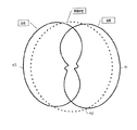
本発明の好ましい実施形態においては、方向制御可能なアンテナにより提供される候補設定は、少なくとも無指向性モード、右方位指向性モードおよび左方位指向性モードを含み。また、より少数あるいはより多数の指向性モードを有するアンテナが採用される場合もある。 In a preferred embodiment of the present invention, candidate settings provided by a direction controllable antenna include at least an omnidirectional mode, a right directional mode, and a left directional mode. In some cases, an antenna having a smaller number or a larger number of directivity modes may be employed.
評価指標は、典型的にはパイロットチャネル信号のような適切な信号の受信の間に測定されるが、またデータペイロード信号のような他のタイプの信号に関して取ることも可能である。 The metrics are typically measured during reception of an appropriate signal, such as a pilot channel signal, but can also be taken for other types of signals, such as data payload signals.
本発明は、非アクティブタイムスロットの間に評価指標を取ることができるので、時分割複信方式(TDD)システムにおいて特に有利である。加えて、典型的なTDDシステムにおいては、任意の所与のタイムスロットにおいて上りリンクあるいは下りリンクのどちらかがアクティブであるので、上りリンクおよび下りリンク通信チャネルに対する調整がより容易に決定される。 The present invention is particularly advantageous in time division duplex (TDD) systems because it can take metrics during inactive time slots. In addition, in a typical TDD system, adjustments for uplink and downlink communication channels are more easily determined because either the uplink or the downlink is active in any given time slot.
追加的な実施形態としては、本発明は、異なる利得調整要因を選択するために、決定された最適なアンテナ設定を適用(利用)する。その利得調整要因は、特定の決定された指向性モードで動作するシステムに関連した伝送路損失を示し、その場合には送信信号の電力レベルを制御する修正アルゴリズムとして適用される。したがって、たとえば、上りリンクおよび下りリンクの電力レベル設定を設定するのに用いられる典型的な閉ループの電力制御アルゴリズムが、特定の最適設定に関連付けられたアンテナ利得に対して調整される。 As an additional embodiment, the present invention applies (uses) the determined optimal antenna settings to select different gain adjustment factors. The gain adjustment factor indicates a transmission line loss associated with a system operating in a specific determined directional mode, in which case it is applied as a modified algorithm to control the power level of the transmitted signal. Thus, for example, a typical closed-loop power control algorithm used to set the uplink and downlink power level settings is adjusted for the antenna gain associated with a particular optimal setting.
さらなる態様においては、その最適指向性設定はレジスタ、メモリ、あるいは他の記憶装置に格納し、そして既知の割り当てられたアクティブなタイムスロットと同期して読み出すことが可能である。このように、所与のタイムスロットにおいて特定の方向に方向制御されるアンテナを必要とするシステムは、次の隣接したタイムスロットにおいては直ちに別の最適な方向に方向制御されることが可能である。 In a further aspect, the optimal directivity setting can be stored in a register, memory, or other storage device, and read out synchronously with a known assigned active time slot. In this way, a system that requires an antenna that is directed in a particular direction in a given time slot can immediately be directed to another optimal direction in the next adjacent time slot. .
本発明の他の態様は、初期の捕捉モードを最適化するように方向付けられている。初期の検出モードの間に、システムパラメータは無指向性設定のアンテナにより決定される。しかしながら、初期の検出の後に引き続く送信に対して最適な指向角度を決定するために、一組の追加的手順が実行されるのが好都合である。この状況において、最大の期待される伝送路損失に関して、あたかもその初期の探索が指向性モードで行われたかのように、同一の感度を達成するよう無指向性モードの間に取られた測定値が調整される。感度改良要因は、引き続く処理の間に測定されたときに、無指向性および指向性モードの間の利得差として決定される。本発明のこの態様により、そのシステムに対する通信範囲をさらに拡大することを提供するために、指向性モードにおける追加の利得が使用されることを可能とする。 Other aspects of the invention are directed to optimize the initial acquisition mode. During the initial detection mode, system parameters are determined by an antenna with an omnidirectional setting. However, a set of additional procedures is conveniently performed to determine the optimal pointing angle for subsequent transmissions after initial detection. In this situation, for the maximum expected transmission line loss, the measurement taken during the omnidirectional mode to achieve the same sensitivity is as if the initial search was done in the directional mode. Adjusted. The sensitivity improvement factor is determined as the gain difference between the omnidirectional and directional modes when measured during subsequent processing. This aspect of the invention allows additional gain in the directional mode to be used to provide further expansion of communication range for the system.
本発明の好ましい一実施形態の記述が次に続く。この特定の実施形態は、TIA(the Telecommunications Industry Association)の仕様T1.3GPP.25シリーズで規定されるように、UMTS(Universal Mobile Telephone System:ユニバーサル移動体通信システム)のW−CDMA(Wideband Code Division Multiple Access:広帯域符号分割多元接続)として知られているセルラー方式無線通信システムのためのものである。しかしながら、本発明の原理は他のタイプの無線システムに適用される可能性があることを、理解されるべきである。 A description of a preferred embodiment of the invention follows. This particular embodiment is based on the specification T1.3GPP. Of TIA (the Telecommunications Industry Association). As defined in the 25 series, a cellular radio communication system known as UMTS (Universal Mobile Telephone System) is known as W-CDMA (Wideband Code Division Multiple Access). Is for. However, it should be understood that the principles of the present invention may be applied to other types of wireless systems.
(基本動作)
一般にどのようなセルラー方式のシステムにおいても、遠隔のユニットあるいはユーザ装置(UE:User Equipment)と通信する中央BTS(Base Transceiver Station:無線基地局)あるいはアクセスポイント(AP)がある。どのようなシステムも、事実上双方向性である。すなわち、BTSからUEへ(下りリンク)、およびUEからBTSへ(上りリンク)通信する機能を備えなければならない。上りリンクおよび下りリンク通信チャネルの複信化は、2つの基本的な方法で実行することが可能である。すなわち、周波数分割複信方式(FDD:Frequency Division Duplexing)および時分割複信方式(TDD:Time Division Duplexing)である。FDDについては、上りリンクおよび下りリンク通信を実現するために、個別の搬送波周波数が利用される。時分割複信方式(TDD)については、上りリンクおよび下りリンク両方に対して同一の周波数帯が用いられる。しかしながら、TDDの場合には、上りリンクはある特定のタイムスロットの間にアクティブとなり、一方下りリンクは他のタイムスロットの間にアクティブとなる。ユーザからユーザへの通信チャネルは、個別のタイムスロットで時間変調される(TDMA)か、あるいは符号分割多重アクセス(CDMA)かのどちらかである可能性がある。TDD/CDMAおよびTDD/TDMAベース両方のアクセス手法が、現に使用されている。
(basic action)
In general, in any cellular system, there is a central BTS (Base Transceiver Station) or an access point (AP) that communicates with a remote unit or user equipment (UE). Any system is virtually bidirectional. That is, a function of communicating from the BTS to the UE (downlink) and from the UE to the BTS (uplink) must be provided. Duplexing of uplink and downlink communication channels can be performed in two basic ways. That is, there are a frequency division duplexing (FDD) and a time division duplexing (TDD). For FDD, individual carrier frequencies are used to implement uplink and downlink communications. For time division duplex (TDD), the same frequency band is used for both uplink and downlink. However, in the case of TDD, the uplink is active during certain time slots, while the downlink is active during other time slots. The communication channel from user to user can be either time modulated (TDMA) in separate time slots or code division multiple access (CDMA). Both TDD / CDMA and TDD / TDMA based access approaches are currently used.
TDDシステムに対しては、BTSからUEへおよびUEからBTSへの両方の伝送方向において、同一の搬送波符号周波数が用いられるため、伝播チャネルの伝送路損失およびフェージング統計値が両方の方向で同一であろうという意味で、そのチャネルは相互交換の関係である。 For TDD systems, the same carrier code frequency is used in both the BTS-to-UE and UE-to-BTS transmission directions, so that the transmission channel loss and fading statistics are the same in both directions. In that sense, the channels are in an exchange relationship.
図1に注目すると、装置(UE)で利用される典型的なTDD/CDMA型の送受信機が、上位レベルの図として示さている。送受信機は、アンテナサブシステム10、受信機サブシステム20および送信機サブシステム30より構成される。
Turning attention to FIG. 1, a typical TDD / CDMA transceiver used in a device (UE) is shown as a high level diagram. The transceiver includes an
アンテナ10は、本発明の好ましい実施形態によれば、指向性型アンテナである。したがって、アンテナ10は指向性制御装置14を介して接続された多数の放射エレメント12−1、...12−nより構成される。指向性制御装置14は、アンテナエレメント12に対して送信あるいは受信方向を設定するために、制御入力16を受けとる。指向性制御装置14は、切換え器、移相器あるいは集中インピーダンスのような他の要素より構成される場合があり、現状技術で知られている種々の方法により、アンテナエレメント12の組み合わせによる指向性に作用する。
The
デュプレクサ18は、TDDシステムの場合には送受信切換え器18とすることが適切と考えられるが、受信機サブシステム20および送信機サブシステム30の両方を、アンテナサブシステム10に接続することを可能にする。
The
受信機サブシステム20は、受信増幅器21、無線周波数(RF)ダウンコンバータ23、電圧制御発振器(VCO:Voltage Controlled Oscillator)22、および移相器25、1対の乗算器26−1、26−2および1対の帯域通過フィルタ27−1、27−2を含む同相−直交(I/Q:In−phase and Quadrature)復調器28より構成される。現状技術でよく知られている方法により、受信増幅器21は、受信された信号を受け入れ、受信信号を増幅し、そして、受信信号をRFダウンコンバータ23に供給する。
The receiver subsystem 20 includes a receive
VCO22からの入力周波数および場合により帯域選択入力24を与えられると、RFダウンコンバータ23は入力無線エネルギーを中間搬送波(IF)周波数信号に変換する。次に、I/Q復調器28は、同相(I)および直交(Q)の両方のチャネル出力として受信データシンボルを供給する。 Given an input frequency from the VCO 22 and possibly a band select input 24, the RF downconverter 23 converts the input radio energy into an intermediate carrier (IF) frequency signal. The I / Q demodulator 28 then provides received data symbols as both in-phase (I) and quadrature (Q) channel outputs.
送信機30については、1対の乗算器31−1、31−2、直交移相器32および加算器33より構成されるI/Q変調器38に、送信データシンボルが供給される。ローカル参照信号を供給されて、I/Q変調器38は、IF周波数において変調された信号をRFアップコンバータ34に供給する。次に、送信VCO35および任意の帯域選択入力36が、そのIF信号を目的のRF搬送波周波数に周波数変換する。次に、送信増幅器37が、変調された送信信号をデュプレクサ18に供給する。デュプレクサ18では、送受信(T/R)入力によって交互に制御されている。レベル検出回路38は、送信されたRF電力レベルを検出するために用いることができる。T/R入力は、基地局により制御チャネル上に供給されるタイムスロット配置にしたがい、制御される。あるタイムスロットの間は、デュプレクサ18は受信モード(すなわち、下りリンクがアクティブな状態)に設定され、他の時間には送信モード(すなわち、上りリンクがアクティブな状態)に設定され、さらに他の時間には空き状態(タイムスロットがアクティブでない状態)とされる。同様のレベル検出回路29もまた、受信信号の検出信号レベルを決定するために用いることができる。
For the transmitter 30, transmission data symbols are supplied to an I / Q modulator 38 including a pair of multipliers 31-1 and 31-2, a quadrature phase shifter 32 and an adder 33. Given the local reference signal, the I / Q modulator 38 provides the
この特定の実施形態によると、アンテナサブシステム10は指向性制御入力16によって選択可能な3つのモードを有する。図2に注目すると、これらのモードの第1は無指向性モードであり、一般にアンテナ12は、すべての方位角方向において相対的に同じ強度の無指向性の送/受信パターンを備えるように動作する。アンテナ10の第2のモードは右側のパターン41により示され、一般に方位角方向面の右側に向かう放射パターンを備える。同様に、アンテナ10の第3の設定は、一般に方位角方向面の左側に向かうアンテナパターン42を備える。したがって、指向性制御装置14に加えられる適切な入力によって、アンテナ10を3つの指向モード(無指向性、右側指向性、あるいは左側指向性)のうちの1つに設定することが可能である。このように利用することができるアンテナシステムは、当技術分野で周知である。1つの例として、本出願の譲受人である、Tantivy Communicationsにより出願された、特許文献1合衆国特許出版 No. 2003/0048226A1を参照することが可能である。この実施形態においては、3つのアンテナモードのみを用いているが、他の実施形態ではより多数のモードを使用することも可能であることを理解されたい。
According to this particular embodiment,
図3は、集中化された無線基地局( BTS:Base Transceiver Station)が利用されるセルラー方式無線環境における、典型的な状況を説明する。ユーザ装置(UE:User Equipment)は、多くの場合特定のセル39−1の1つの角に位置している。この状態において、そのUEは主としてBTS51−1のパイロットチャネル信号を電力レベルP1で検出することができる。しかしながら、そのUEはまた、電力レベルP2のBTS51−2、電力レベルP3のBTS51−3および電力レベルP4のBS51−4のような他の隣接したBTSに関連した複数の信号を検出することも可能である。したがって、隣接するBTS51−2、51−3および51−4のすべてが、意図されたBTS51−1からの希望信号の受信に対し干渉の原因になる可能性があり、また同様に、UEから意図したBTS51−1までの送信に干渉する場合もあると理解することができる。したがって、全体的なシステム性能を最適化するために、アンテナ10の指向性を考慮に入れる種々の解決方法を用いることが可能である。
FIG. 3 illustrates a typical situation in a cellular radio environment where a centralized radio base station (BTS) is utilized. A user equipment (UE: User Equipment) is often located at one corner of a specific cell 39-1. In this state, the UE can mainly detect the pilot channel signal of the BTS 51-1 at the power level P1. However, the UE can also detect multiple signals associated with other adjacent BTSs such as BTS 51-2 at power level P2, BTS 51-3 at power level P3 and BS 51-4 at power level P4. It is. Therefore, all of the adjacent BTSs 51-2, 51-3 and 51-4 can cause interference with the reception of the desired signal from the intended BTS 51-1, and similarly from the UE It can be understood that the transmission up to the BTS 51-1 may interfere. Thus, various solutions that take into account the directivity of the
本発明により描かれるアルゴリズムは、UEにて測定された受信信号電力および干渉信号電力の大きさを利用する。これらは、図4に示されるような追加的受信回路により提供され得る。受信回路60は、受信Iチャネル(RxI)および受信Qチャネル(RxQ)を測定し、それらを典型的な電力レベル検出器61に供給することができる。RxIおよびRxQ信号はまた、特定のチャネルに対するアクティブなCDMA符号が入力されている復調器62に供給される場合がある。そして復調器62は、受信符号信号電力(RCSP:Receive Code Signal Power)の大きさを与える。
The algorithm depicted by the present invention utilizes received signal power and interference signal power magnitudes measured at the UE. These can be provided by an additional receiving circuit as shown in FIG. The receiving circuit 60 can measure the received I channel (RxI) and the received Q channel (RxQ) and supply them to a typical
隣接した基地局51−2、51−3、51−4に関連した受信干渉電力の推定値は、追加的な復調器63−1、63−2、・・・63−P、加算回路64および減算回路65により提供される。すなわち、BTS51−1からのアクティブでないCDMA符号(そのUEにより現在利用されてないチャネルに対する符号)を適用された追加的復調器を用いて、加算回路64においてそれらの合計を取ることにより、そのようなセル内干渉チャネルの相対的な信号電力が個別に提供される。次に、この値は全体的受信電力の推定値から取り除かれ(減算回路65により)、干渉符号チャネル信号電力(ICSP:Interfering Code Channel Signal Power)を推定する。
Received interference power estimates associated with adjacent base stations 51-2, 51-3, 51-4 include additional demodulators 63-1, 63-2,... 63-P, adder circuit 64, and Provided by the
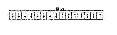
ここで本発明は、上りリンク(UL)および下りリンク(DL)方向の両方において、すべての特定のアクティブなタイムスロットに対する最適なアンテナモード設定を選択する必要であるだろうということが理解できる。図5は、その状況を示す上位レベルの図である。下りリンクのタイミング図70が、上りリンクのタイミング図75とともに説明されている。下りリンクタイミング70およびUTMS WCDMAフレームは、次のように割り当てられる。1フレームは、全体で10ミリセカンド(ms)の時間を有しており、そして毎秒3.84メガチップ(Mc/s)の符号チップ時間(tc)の2560倍である、15個のタイムスロット(ts)に細分される。したがって、1つのタイムスロットはCDMA拡散符号の2560チップに対応する。タイムスロットについての物理的内容は、W−CDMA仕様補節5.2.2において記述される対応する長さのバーストである。タイムスロットのそれぞれは、上りリンク( UL )あるいは下りリンク( DL )のいずれにも割り当てることが可能である。こうした柔軟性により、時分割複信方式の機能は異なる環境や配置シナリオに適応させることができる。いずれの構成においてもそれぞれのフレームで、少なくとも1つのタイムスロットが下りリンクに割り当てられねばならず、また少なくとも1つのタイムスロットが上りリンクに割り当てられねばならない。 It can now be seen that the present invention will need to select the optimal antenna mode settings for all specific active time slots in both the uplink (UL) and downlink (DL) directions. FIG. 5 is a high-level diagram showing the situation. A downlink timing diagram 70 is illustrated along with an uplink timing diagram 75. The downlink timing 70 and the UTMS WCDMA frame are allocated as follows. A frame has a total time of 10 milliseconds (ms) and 15 time slots (2560 times the code chip time (tc) of 3.84 megachips (Mc / s) per second ( ts). Therefore, one time slot corresponds to 2560 chips of the CDMA spreading code. The physical content for the time slot is a corresponding length burst as described in W-CDMA Specification Supplement 5.2.2. Each time slot can be assigned to either the uplink (UL) or the downlink (DL). With this flexibility, the time division duplex functionality can be adapted to different environments and deployment scenarios. In any configuration, in each frame, at least one time slot must be assigned to the downlink, and at least one time slot must be assigned to the uplink.
したがって、図5に示されるような状況が、展開される。すなわち、隣接したタイムスロット71−1および71−2は、それぞれ左のモードにそして引き続き右のモードに連続して最適に指向制御される。その後のタイムスロット71−3は、アンテナを無指向性の設定により最適化することを必要とする場合があり、一方、次のスロット71−4(空きスロットの後の)は、左のモードに最適に指向制御される必要がある場合がある。同様に上りリンク方向においても、隣接したタイムスロット72−1、72−2および72−3はそれぞれ右、無指向性、そして右のモードにアンテナを設定することを必要とする場合がある。アンテナのポジション(position)は、それぞれのアクティブなタイムスロットに関連付けられているということ、および、網掛けのない部分71−5および71−6で示されるような非アクティブタイムスロットも、本アルゴリズムにしたがって測定をするために利用される場合があるということも、図5から理解すべきである。 Therefore, the situation as shown in FIG. 5 is developed. That is, the adjacent time slots 71-1 and 71-2 are optimally controlled in the left mode and subsequently in the right mode, respectively. Subsequent time slot 71-3 may require the antenna to be optimized with an omnidirectional setting, while the next slot 71-4 (after the empty slot) is in the left mode. There may be cases where optimal directional control is required. Similarly, in the uplink direction, adjacent time slots 72-1, 72-2, and 72-3 may require the antenna to be set to the right, omnidirectional, and right modes, respectively. The antenna position is associated with each active time slot, and inactive time slots as shown in the unshaded portions 71-5 and 71-6 are also included in the algorithm. Thus, it should also be understood from FIG. 5 that it may be used to make measurements.
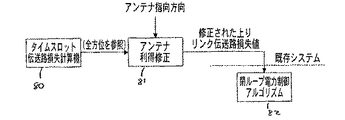
本発明によるアルゴリズムを全体として適用する結果、単にアンテナポジションが最適化されるということだけでなく、また修正された伝送路損失が計算され得る。特に、図6に示されるように、受信アンテナの無指向性設定に関連付けられた伝送路損失を提供するため、タイムスロット伝送路損失計算機が典型的に利用される。しかしながら、アンテナの利得はその指向性モードにしたがって変化するので、任意の上りリンク伝送路損失推定を修正するために、アンテナ利得修正ステップ81が選ばれるべきである。このように、アンテナポジション設定条件を与えられて、上りリンク伝送路損失推定値を修正するためにアンテナ利得修正81が適用されることが可能であり、修正された伝送路損失値は次に閉ループ電力制御アルゴリズム82に適用される。本発明は、このように信号の受信における受信感度向上を可能とするだけではなく、閉ループ電力制御処理を最適化することが可能なさらなる利点をもたらす。
As a result of applying the algorithm according to the invention as a whole, not only is the antenna position optimized, but also a corrected transmission line loss can be calculated. In particular, as shown in FIG. 6, a time slot transmission line loss calculator is typically utilized to provide the transmission line loss associated with the omnidirectional setting of the receiving antenna. However, since the antenna gain varies according to its directivity mode, an antenna gain modification step 81 should be chosen to modify any uplink transmission line loss estimate. In this way, given the antenna position setting condition, an antenna gain correction 81 can be applied to correct the uplink transmission line loss estimate, and the corrected transmission line loss value is then closed loop. Applied to the
図7は、下りリンク(DL)方向、すなわち無線基地局(BTS:Base Transceiver Station、またW−CDMA仕様ではノードBと呼ばれる)から送信されユーザ装置において信号を受信するための、最適なアンテナ設定を決定するのに利用することが可能なステップのフロー図である。 FIG. 7 shows an optimum antenna configuration for receiving a signal in the user equipment transmitted from the downlink (DL) direction, that is, a radio base station (BTS: Base Transceiver Station, also called Node B in the W-CDMA specification) FIG. 6 is a flow diagram of the steps that can be used to determine
この方法の第1のステップでは、タイムスロット割り当てが行われる。これらの割り当ては、図5に関連して記述されたように、下りリンクについて割り当てられたアクティブなスロットおよび割り当てられた非アクティブスロットの両方に対するものである。このとき、このプロセスによりモニタされるタイムスロットの合計の数が規定される。典型的にはノードBあるいは他の集中化された制御装置により、ノードBが認識している条件に基づいて対象のユーザ装置に対して適切な方法で、タイムスロット割り当てが為されるであろう。 In the first step of the method, time slot allocation is performed. These assignments are for both active and assigned inactive slots assigned for the downlink, as described in connection with FIG. At this time, the total number of time slots monitored by this process is defined. Typically, a time slot assignment will be made by a Node B or other centralized controller in a manner appropriate to the target user equipment based on conditions known by the Node B. .
状態92でモニタされたそれぞれのスロットに対して、次のステップの状態94においてRCSPおよびICSPの両方がそれぞれのアンテナモードに対して測定される。したがって、アンテナ10は無指向性、右、あるいは左の3モードのそれぞれに一時的に設定され、RCSPおよびICSPの両方が決定される。
For each slot monitored in state 92, both RCSP and ICSP are measured for each antenna mode in state 94 of the next step. Therefore, the
状態96において、アンテナのそれぞれのモードに対するRCSPおよびICSPの測定値は、適切なローパスフィルタおよび/あるいは平均化計算によりフィルタされる。 In state 96, the RCSP and ICSP measurements for each mode of the antenna are filtered by an appropriate low pass filter and / or averaging calculation.
状態98において、ユーザ装置(UE)は次に、これらの測定値の報告をノードBに送り返す。これらは少なくともアクティブなタイムスロットに対して測定されたRCSP、およびアクティブなスロットおよび非アクティブスロットの両方で測定されたICSPを含むであろう。これにより、ノードBはアクティブなスロットに対する信号対干渉比を決定することが可能になる。したがって、次にこの情報により、種々のアンテナ設定で観測された信号対干渉比(SIR:Signal to Interference Ratio)に基づいて、ユーザ装置(UE)にアクティブなスロットを割り当てることが可能になる。 In state 98, the user equipment (UE) then sends a report of these measurements back to the Node B. These will include at least the RCSP measured for active time slots and the ICS measured in both active and inactive slots. This allows Node B to determine the signal to interference ratio for the active slot. Therefore, this information can then be used to assign active slots to user equipment (UE) based on signal-to-interference ratio (SIR) observed at various antenna settings.
この状態から、次にアクティブおよび非アクティブなスロットに対するICSPとRCSPの比率としてSIRを計算することによって、最適な指向方向を状態102において決定することが可能である。すなわち、RCSPはアクティブなスロットに対して取られ、そしてICSP測定は非アクティブスロット(このスロットでは、干渉信号電力のみが存在したことが知られている)から取られる。このようにして、無指向性、左あるいは右のいずれかの最適なアンテナ設定を、測定値から決定することが可能である。 From this state, the optimal pointing direction can be determined in state 102 by calculating the SIR as the ratio of ICSP and RCSP for the next active and inactive slots. That is, the RCSP is taken for the active slot, and the ICSP measurement is taken from the inactive slot (it is known that only interference signal power was present in this slot). In this way, it is possible to determine the optimal antenna setting of omnidirectional, left or right, from the measured values.
他のアンテナ指向方向に対する下りリンク(DL)方向のRCSPおよびISCPのアクティブなスロットでの測定値は、適切な信号上において、そしてたとえば重要なユーザデータが送られていない時間に取ることが可能である。これはパイロット同期送信あるいは同様な信号が送信されている時間に取られる場合があるが、その測定値はまたデータ信号の送信時でも、また他の時間の場合においても取ることが可能であることを理解されるべきである。 Measurements in the active slot of the RCSP and ISCP in the downlink (DL) direction with respect to other antenna pointing directions can be taken on the appropriate signal and at times when no important user data is being sent, for example. is there. This may be taken at the time the pilot synchronous transmission or similar signal is being transmitted, but the measurement can also be taken at the time of the data signal transmission and at other times. Should be understood.
アンテナに対する指向性設定条件が与えられると、次に図8に示されるように、順方向(DL)伝送路損失を推定することが可能である。この場合、所与のアンテナに対する利得はもはや既知である。ここで、この更新されたアンテナ利得設定は、順方向伝送路損失推定(FPL:Forward Path Loss estimate)を修正するのに用いることが可能であり、次に状態106において、閉ループ電力制御アルゴリズムで利用される。例えば、閉ループの電力制御アルゴリズムにおいては、上りリンクの推定(これは逆方向の伝送路損失である)が、下りリンク(順方向)伝送路損失測定に基づいて為されることがしばしばある。基地局が、その送信電力レベルおよび遠隔ユニットにより信号が受信された電力レベル(報告が送り返される)を知ると、次にその送信を通してどのくらいのエネルギーが失われたか算定することが可能である。典型的な電力制御アルゴリズムは、次に、下りリンク測定値に基づいて、上りリンクすなわち逆方向の伝送路損失を推定しなければならない。この特定な状況においては、アンテナがその角度設定に基づいて異なる利得を経験するであろうとすれば、その角度設定は、次に上りリンク伝送路損失を修正するために使用される修正された利得値を提供するのに用いることが可能である。
Given the directivity setting conditions for the antenna, it is then possible to estimate the forward (DL) transmission line loss, as shown in FIG. In this case, the gain for a given antenna is no longer known. Here, this updated antenna gain setting can be used to modify the Forward Path Loss estimate (FPL), which is then utilized in the closed loop power control algorithm at
別の考え方によれば、伝送路損失に対する推定は両方の方向について修正されねばならない。順方向のリンク調整は、アンテナ利得に対する伝送路損失を修正するために用いられる。第二に、逆方向のリンク調整は、次にユーザ装置がその基地局に返信を試みる場合に、ユーザ装置における実際の逆方向のリンク送信電力レベル設定を修正するために用いられる。 According to another way of thinking, the estimation for transmission line loss must be corrected in both directions. Forward link adjustment is used to correct transmission line loss for antenna gain. Second, reverse link adjustment is used to modify the actual reverse link transmit power level setting at the user equipment the next time the user equipment attempts to reply to its base station.
図9は、ユーザ装置が送信するのに用いられる上りリンクに対して、最適な指向角度を決定するために用いられる一連のステップのフロー図である。最初の状態150では、すべての指向角度において、隣接セルの干渉の測定値が決定される。すなわち、隣接BTS(51−2、51−3、51−4)に対する共通制御チャネル信号が、すべての指向角度において測定される。状態152では、その送信の間に、隣接したBTS51−2、51−3、51−4に対する干渉を最小にしつつ、目的のBTS51−1への上りリンク電力を最大にするように方位が選択される。すなわち、状態150において、ユーザ装置は取り得るアンテナ角度設定のそれぞれに対して、隣接したBTSに対する逆方向リンクの伝送路損失を決定し、次にUEからの送信により引き起こされる干渉レベルを計算する。その結果、隣接したBTS51−2、51−3および51−4に対する、隣接したレベルの干渉レベルを最小にしつつ、目的の基地局51−1への電力を最大にするような、全体的に最適な設定が選択される。この概念はUMTS W−CDMAで利用される、本発明の実施形態の記述に関連して、以下にさらに詳細に記述される。
FIG. 9 is a flow diagram of a series of steps used to determine the optimum pointing angle for the uplink used by the user equipment to transmit. In the
代替の案においては、状態154では、隣接した基地局の基地局負荷が監視される場合がある。すなわち、それぞれの基地局は、相対的にどのくらい繁忙か、つまりいくつのタイムスロットがアクティブであるかを示すデータを、周期的に報知する場合がある。もし、状態156において、隣接する基地局が特に負荷が多いと検知されると、その場合は状態158において、その特定の隣接局に対する干渉を減らす方位が選択される。したがって、例えばユーザ装置(UE)は、隣接した基地局51−3がそのタイムスロットの大部分をアクティブな状態に割り当てられており、特に繁忙であると判定することができる。もし、この特定の隣接局が他の隣接する基地局より相対的により繁忙であり、そして特にもし現在割り当てられている基地局が特に繁忙ではないのなら、その場合はその繁忙な隣接する基地局に対する干渉を減少させる方位が選択されるであろう。したがって、UEおよびその目的の基地局51−1の間の目的のリンクに及ぼす悪影響を最小にして、全体的なシステムパフォーマンスを改善することが可能である。
In an alternative, state 154 may monitor the base station load of adjacent base stations. That is, each base station may periodically broadcast data indicating how busy is relatively, that is, how many time slots are active. If it is detected in state 156 that an adjacent base station is particularly loaded, then in
再び繰り返せば、上りリンク方向に関してもステップ160のように、上りリンクおよび下りリンクアンテナ方位設定の利得の差に対して、伝送路損失計算が調整されるべきである。 Again, the transmission path loss calculation should be adjusted for the uplink and downlink antenna azimuth setting gain differences as in step 160 for the uplink direction as well.
図10は、上りリンクおよび下りリンクの両方向が複信方式のシステムで、すなわちそれぞれのタイムスロット(TS)の間に、上りリンクおよび下りリンクの両方のタイムスロットがアクティブになるシステムで、利用される可能性がある1つのシナリオを説明する。しかしながら、図11A、11B、11C、および11Dに示されるような、他の割り当てが典型的でありまた可能である。これらの図はそれぞれ以下のように、上りリンクおよび下りリンクに対するタイムスロット構成を示す。すなわち、対称の上りリンクおよび下りリンク割り当てを有する複数切換え位置構成、非対称の下りリンクおよび上りリンク割り当てを有する複数切換え位置構成、対称の下りリンクおよび上りリンク割り当てを有する単一切換え位置構成、および非対称の下りリンクおよび上りリンク割り当てを有する単一切換え位置構成である。 FIG. 10 is used in a system in which both uplink and downlink directions are duplexed, that is, in a system in which both uplink and downlink time slots are active during each time slot (TS). Explain one possible scenario. However, other assignments are typical and possible, as shown in FIGS. 11A, 11B, 11C, and 11D. These figures show the time slot configurations for the uplink and downlink, respectively, as follows. Multiple switching position configurations with symmetric uplink and downlink assignments, multiple switching position configurations with asymmetric downlink and uplink assignments, single switching position configurations with symmetric downlink and uplink assignments, and asymmetric Single switching position configuration with multiple downlink and uplink assignments.
したがって、TDDシステムでは、最適化されたアンテナ設定を実現するために、そのアレイに対するある種の方位制御が実現されねばならない。もしソフトウェアが十分に高速であれば、そのアレイの方位制御は指向性制御装置の入力16にメッセージを送るソフトウェアにより実行される場合がある。しかしながら、もしソフトウェアが十分に高速に実行することができないなら、ソフトウェアの管理の下で動作するハードウェア状態の機構が必要とされる場合がある。このアレイ設定コプロセッサ(ASCP:Array Setting CoProcessor)は、次のタイムスロットのための値が入っているレジスタと同程度に単純である場合がある。このような実施形態において、その値は的確な時間に読み出されるであろう。 Thus, in a TDD system, some sort of azimuth control for the array must be realized in order to achieve an optimized antenna setting. If the software is fast enough, the orientation control of the array may be performed by software that sends a message to the input 16 of the directivity controller. However, if the software cannot run fast enough, a hardware state mechanism that operates under the management of the software may be required. This array setting coprocessor (ASCP) may be as simple as a register containing a value for the next time slot. In such an embodiment, the value will be read at the correct time.
より高度なASCPは、設定されるべき次のN個のアレイ位置に対する値を含む、多数のレジスタを必要とする場合がある。ソフトウェアは、タイムスロットが実際に到達する前に、このレジスタに書き込むことができる。次に、的確な時間に、ASCPはアンテナアレイ上の制御入力16にこの設定を適用するであろう。 A more sophisticated ASCP may require a large number of registers, including values for the next N array locations to be set. Software can write to this register before the time slot actually arrives. Next, at the correct time, ASCP will apply this setting to the control input 16 on the antenna array.
図12は、より高度なASCPの例を示している。この多点制御装置は、上に記述された制御装置と同様に動作するが、それぞれに設定値を含む多数のレジスタを、異なる時間に適用することが可能である。ASCPのこのような実施方法は、受信モード(下りリンク)および送信(上りリンク)に割り当てられたタイムスロットに対するレジスタを含む、多数のレジスタを有する。アレイレジスタは、すべて同時に一度に設定することも、あるいは必要なときに個別に変更することも可能である。再びソフトウェアのタイミング的制約により規定されるが、任意の時間に書き込むことを可能にするために、二重にバッファーすることもまた可能である。 FIG. 12 shows an example of a more advanced ASCP. This multipoint control device operates in the same way as the control device described above, but it is possible to apply multiple registers, each containing a set value, at different times. Such an implementation of ASCP has a number of registers, including registers for time slots assigned to receive mode (downlink) and transmit (uplink). The array registers can be set all at once at the same time, or can be changed individually when needed. Again defined by software timing constraints, it is also possible to double buffer to allow writing at any time.
図12により提案されるように、さらなる実施形態では、上りリンクタイムスロット割り当てが下りリンク割り当てから固定的時間間隔だけオフセットしている場合があることを認識されたい。この環境では、デュプレクサ18は、常に、予め決定された時間間隔で、送信および受信モードの間を切り換えるように設定されるであろう。図12のタイミング図に示されるように、ユニット番号1であると識別される特定のユーザ装置(UE)は、下りリンク方向で最初に説明されたタイムスロットでアクティブとなり、そして上りリンク方向においては、2タイムスロットだけ遅れてアクティブになるであろう。ASCPの論理はこのように、フレームの初めに交互のタイムスロットで送信および受信モード間を切り換えることを常に承知している。上りリンクおよび下りリンクタイムスロットの割り当てに関して、少しだけより厳密な構造を採用することにより、ASCPアーキテクチャをこのように単純化することに貢献することができる。
It should be appreciated that in a further embodiment, the uplink time slot assignment may be offset from the downlink assignment by a fixed time interval, as proposed by FIG. In this environment, the
UMTS−TDDについての記述
ここで、本発明がUMTD−TDDシステム環境で、どのように用いることができるかについて、読者はより詳細な記述を享受するであろう。以下の論議は、読者がUMTD−TDDシステムの仕様およびUMTD−TDDシステムが定義する種々のチャネルに精通しているものと想定する。
Description of UMTS-TDD The reader will now enjoy a more detailed description of how the present invention can be used in a UMTD-TDD system environment. The following discussion assumes that the reader is familiar with the specifications of the UMTD-TDD system and the various channels defined by the UMTD-TDD system.
1.定常状態
上記参照されたW−CDMA仕様で定義されるように、定常状態のケースはCELL_FACHあるいはCELL_DCHのどちらかである。CELL_DCHは、UEが音声および/あるいはデータのトラフィックにアクティブに従事している状態である。DLおよびULスロット/符号/電力割り当てが、RRM制御の下で変化している場合があり、UEが移動性である場合がある。CELL_FACHは、UEが割り当てられたリソースを有しておらず、RRMによる将来の割り当てに備えて、雑音測定値が報告されており、UEが移動性である場合がある状態である。
1. Steady state As defined in the above-referenced W-CDMA specification, the steady state case is either CELL_FACH or CELL_DCH. CELL_DCH is a state in which the UE is actively engaged in voice and / or data traffic. DL and UL slot / code / power allocation may be changing under RRM control and the UE may be mobile. CELL_FACH is a state in which the UE does not have assigned resources, noise measurements are reported for future assignment by the RRM, and the UE may be mobile.
1.1 下りリンク
図7で概説され、そして下に詳述されるアルゴリズムの概念は、DL方向に対して、隣接セル/セクタの干渉に対する信号の比率(SIR)を最大化するように、アンテナ10が方向制御されることを想定している。上に簡単に記述されたように、SIRに基づいて方向制御を決定することは、アクティブなスロット(UEに対してトラフィックを運んでいるスロット)および非アクティブスロットの両方に対して、目的の信号(RCSP)の測定および隣接するセルの干渉(ICSP)の測定を必要とする。UEが移動性で、かつ/あるいは、隣接するセクタあるいはセルに関してスロット割り当てが変化している場合、アクティブなスロットに対するSIR(すなわち、RCSP/ICSP)測定は、最適な制御方向を保ち続けることを必要とされる。非アクティブスロットに対するSIR測定は、そのスロットが将来の割り当てでアクティブになった場合に、正しい制御方向を提供することを必要とされる。典型的には、P−CCPCH信号に対するRSCP(Received Signal Code Power:受信信号符号電力)および専用のタイムスロットに対するISCP(Interference Signal Code Power:干渉信号符号電力)の測定が行われる。
1.1 Downlink The algorithm concept outlined in FIG. 7 and detailed below is based on the concept that the antenna to maximize the ratio of signal to adjacent cell / sector interference (SIR) in the DL direction. 10 is assumed to be direction-controlled. As described briefly above, determining direction control based on the SIR may be the target signal for both active slots (slots carrying traffic to the UE) and inactive slots. (RCSP) measurement and adjacent cell interference (ICSP) measurement are required. If the UE is mobile and / or the slot assignment is changing with respect to adjacent sectors or cells, SIR (ie RCSP / ICSP) measurements for active slots need to keep the optimal control direction It is said. SIR measurements for inactive slots are required to provide the correct control direction if that slot becomes active in a future assignment. Typically, RSCP (Received Signal Code Power) for a P-CCPCH signal and ISCP (Interference Signal Code Power) for a dedicated time slot are measured.
1.1.1 RX信号電力測定
他のRRM機能あるいは共通制御チャネルパイロット電力信号P−CCPCH RSCPの支援を受けながら、信号電力測定はUEによっても行われる。指向性のあるUEアンテナを付加するためには、アンテナの全ての可能な指向方向に対して、P−CCPCH RSCP測定が行われることが必要となる。もしUEにおいて3モードのアンテナが用いられるなら、P−CCPCH RSCP測定は無指向性モード、左ビームおよび右ビームモードにおいて行われなければならない。P−CCPCH RSCP測定は、UEがトラフィックあるいは報知チャネル上でデータ(CELL_DCH)を受信しているスロットに関してのみ行われる。指向性アンテナについては、この測定はその3種のビームポジション(無指向性、左、右)の内の選択された1種に対するものになるであろう。他の2つの指向性に対する測定は、これらの方向でのSIRが受信時点の方向と比較して、悪化している可能性があるため、UEがデータを受信するように要求されていないときに、P−CCPCH上で行われることが可能である。P−CCPCHは、常に無指向性モードのアンテナの基地局から送られるので、非アクティブスロットの間の他のポジションでのP−CCPCH受信電力の測定値は、同一方向のアクティブなスロットのP−CCPCH受信電力と同一であろう(そのスロットが時間的に近く、さらにステップ96(図7)のようにある量の平均化が為されることを想定して)。
1.1.1 RX signal power measurement Signal power measurement is also performed by the UE with the assistance of other RRM functions or the common control channel pilot power signal P-CCPCH RSCP. In order to add a directional UE antenna, P-CCPCH RSCP measurements need to be performed for all possible directional directions of the antenna. If a 3-mode antenna is used at the UE, P-CCPCH RSCP measurements must be made in omni-directional, left beam and right beam modes. P-CCPCH RSCP measurement is performed only for the slot in which the UE is receiving data (CELL_DCH) on traffic or broadcast channel. For a directional antenna, this measurement will be for a selected one of its three beam positions (omnidirectional, left, right). Measurements for the other two directivities are when the UE is not required to receive data because the SIR in these directions may be worse compared to the direction at the time of reception. Can be performed on the P-CCPCH. Since the P-CCPCH is always sent from the antenna base station in the omnidirectional mode, the measured P-CCPCH power at other positions during the inactive slot is the P- It will be the same as the CCPCH received power (assuming that the slot is close in time and a certain amount of averaging is done as in step 96 (FIG. 7)).
1.1.2 セル間干渉の測定
タイムスロットのISCP測定を通してRRMを支援によって、セル間干渉の測定はまた、UEによっても行われる。ここでの議論の目的のために、ISCPはセル間干渉電力のみを提供するものと仮定する。指向性のあるUEアンテナでは、アンテナのすべての可能な指向モードの方向でタイムスロットISCP測定の行われることが要求される。したがって、もし3モードのアンテナ10がUEで用いられるならば、それぞれの干渉している可能性のある符号に対して、無指向性、左および右のビームモードで、ISCP測定が行われる。アクティブなスロットの測定に対しては、現在の指向ポジションでのみ測定が行われる(アンテナの方向制御により、アクティブなチャネルの受信機能が変動する可能性がある)。定義により、アクティブなスロットに対する他のポジションは、SIRが悪化するであろう。したがって、他のポジションでデータを受信(CELL_DCH)しようと試みると、性能を悪化させる傾向を示す可能性がある。
1.1.2 Inter-cell interference measurements With the aid of RRM through ISCP measurements of time slots, inter-cell interference measurements are also made by the UE. For the purposes of this discussion, it is assumed that ISCP provides only inter-cell interference power. A directional UE antenna requires time slot ISCP measurements to be made in the direction of all possible directional modes of the antenna. Thus, if a three-
1.1.3 RX信号電力報告
P−CCPCH RSCP測定値はまた、電力制御のために、およびDLおよびULのタイムスロット割り当ての目的のために、周期的に無線ノード制御装置(RNC)に報告される。3モードアレイ10のような指向性アンテナでは、RSCPの3つの異なる測定が行われる。3つの測定値のすべては、UEによりアンテナの将来の指向方向の決定に用いられるが、現時点の指向方向のRSCP測定値のみがRNCに報告される。生のRSCP測定値は、UEによって報告する(ステップ98)のに用いられる前に、種々のレベルのフィルタを通される(ステップ96)。すべての方向に対するRSCP測定値は、それが報告のために用いられるか用いられないに拘わらず、現実施方法と同様にフィルタされる。その報告には、現在の指向方向に関連付けられた平均値を用いる。
1.1.3 RX signal power reporting P-CCPCH RSCP measurements are also reported to the radio node controller (RNC) periodically for power control and for DL and UL time slot allocation purposes. Is done. For directional antennas such as the three-
1.1.4 セル間干渉報告
タイムスロットISCP測定値は、順方向チャネル(DL)割り当て目的のために、RNCに周期的に報告される。RNCは、測定されるべきタイムスロットを指定する。3モードの指向性アンテナにより、それぞれのタイムスロットに対して、3つの異なるISCPの測定が行われる。ISCPスロット報告が、アクティブなスロット(そのUEにより用いられているスロット)に対するものである場合は、報告されたISCP値は現時点のアンテナ指向方向から取られた値である。ISCPスロット報告が非アクティブスロット(将来の割り当てを考慮してのスロット)に対するものである場合は、報告されたISCP値は最大のSIRを提供するアンテナ方向から取られた値である。生のISCP測定値は、UEによる報告のために用いられる前に、種々のレベルのフィルタを通される。すべての方向および全てのスロットに対するISCP測定値は、それが報告のために用いられるか用いられないかに拘わらず、現実施方法と同様にフィルタされる。したがって、報告ステップ98は、アクティブなスロットのISCP報告のためには、現在の指向方向に関連付けられた平均値を、非アクティブスロットのISCP報告のためには、最大のSIRの方向に関連付けられた平均値を用いる。
1.1.4 Inter-cell interference reporting Time slot ISCP measurements are periodically reported to the RNC for forward channel (DL) assignment purposes. The RNC specifies the time slot to be measured. With a three-mode directional antenna, three different ISCP measurements are made for each time slot. If the ISCP slot report is for an active slot (the slot used by the UE), the reported ISCP value is taken from the current antenna pointing direction. If the ISCP slot report is for an inactive slot (a slot that allows for future assignments), the reported ISCP value is taken from the antenna direction that provides the maximum SIR. Raw ISCP measurements are passed through various levels of filters before being used for reporting by the UE. The ISCP measurements for all directions and all slots are filtered in the same way as the current implementation, regardless of whether it is used for reporting. Thus, reporting step 98 is associated with the average value associated with the current pointing direction for ISCP reporting of active slots and with the maximum SIR direction for ISCP reporting of inactive slots. Use the average value.
1.1.5 アクティブなスロットに対する指向方向
すべての指向方向に対するアクティブなスロットあるいはスロット群に対するSIR(ISCPに対するRSCPの比率)を計算することにより、UEアンテナの現在の指向方向が決定される。次に、次のスロット時間の直前に、アンテナポジションは最大のSIRの方向に調整される。アクティブなタイムスロットに対して報告されるRSCPおよびISCPの値は、選択された方向に対するSIRを決定するために用いられたその値である。ここで、次のことに注意をしておくべきである。すなわち、P−CCPCHに対するRSCPは、無指向性モードで送信している基地局とともに計算されるため、もしノードB(割り当てられた無線基地局)それ自身が指向性のあるビームを形成するアンテナを用いているならば、アンテナ方向制御アルゴリズムにより計算されたSIRは、順方向電力制御において閾値により維持されたSIRと同じではないであろう。しかしながら、指向性アンテナは隣接セルの干渉を減少させるので、無指向性で送信するノードBについての指向方向全体のSIRの傾向は、ビームを形成する形で送信するノードBについての指向方向全体のSIRの傾向と、相対的にみて同じであるべきである。
1.1.5 Directional Direction for Active Slots By calculating the SIR (ratio of RSCP to ISCP) for active slots or slots for all directivity directions, the current directivity direction of the UE antenna is determined. Next, just before the next slot time, the antenna position is adjusted in the direction of the maximum SIR. The RSCP and ISCP values reported for active timeslots are those values used to determine the SIR for the selected direction. Here, you should pay attention to the following. That is, the RSCP for P-CCPCH is calculated with the base station transmitting in the omni-directional mode, so if the Node B (assigned radio base station) itself forms a directional beam If used, the SIR calculated by the antenna direction control algorithm will not be the same as the SIR maintained by the threshold in forward power control. However, directional antennas reduce adjacent cell interference, so the SIR trend across the directional direction for Node B transmitting omni-directionally is the same as The SIR trend should be relatively the same.
1.1.6 非アクティブスロットに対する指向方向
UEにより測定されたアクティブでないDLのそれぞれのスロットは、独立した指向方向を有するであろう。非アクティブスロットに対する指向方向は、最大のSIRを提供する方向である。もし非アクティブスロットがUEに割り当てられるなら、その後、そのアンテナポジションはそのスロット時間の直前の最大のSIRの方向を指向制御するように調整される。そのスロットは、アクティブなスロットであるとみなされる。
1.1.6 Directional Direction for Inactive Slots Each slot of the inactive DL measured by the UE will have an independent pointing direction. The pointing direction for the inactive slot is the direction that provides the maximum SIR. If an inactive slot is assigned to a UE, then its antenna position is adjusted to direct the direction of the maximum SIR just before that slot time. That slot is considered to be the active slot.
1.1.7 順方向伝送路損失
図6で言及したように、指向性アンテナを組み込むことによって、その指向性パターンおよび無指向性パターンの間で利得の差異が生ずるため、順方向伝送路損失の計算に影響が出てくる。アンテナが無指向性モードおよび指向性モードの間で切換えられるときは、その補償が為されない限り、順方向伝送路損失は変化するように思われるであろう。利得におけるこの差異は、無指向性モードに対して測定されたRSCPについて、および2つの指向性モードのそれぞれに対して測定されたRSCPについての相互の差異に基づいて計算することができる。無指向性モードおよび指向性モードの間の正確な利得差は、指向性アンテナへの到来角に依存するため、この利得差は推定するよりも測定されるべきである。
1.1.7 Forward Transmission Line Loss As mentioned in FIG. 6, the incorporation of a directional antenna causes a gain difference between the directional pattern and the omnidirectional pattern. Will affect the calculation. When the antenna is switched between omnidirectional and directional modes, the forward transmission path loss will seem to change unless it is compensated. This difference in gain can be calculated based on the mutual difference for the RSCP measured for the omni-directional mode and for the RSCP measured for each of the two directional modes. Since the exact gain difference between the omnidirectional and directional modes depends on the angle of arrival at the directional antenna, this gain difference should be measured rather than estimated.
1.1.8 閉ループ順方向電力制御
あるアクティブなスロットに対してアンテナ方向が変化した場合、指向性アンテナを組み込むことにより、順方向(DL)電力制御にもまた影響が出る。そのポジションが調整されたときに、順方向(DL)電力制御により、場合によっては順方向電力がステップ状に変化し、そしてさらに重要なのはSIRのステップ状の変化が見られるだろう。アンテナポジションが変更された場合には、その新しいポジションは現時点のポジションより高いSIRを有するだろう(さもなければ、ポジションが変更されなかったであろう)。アンテナポジションが変更されたときには、順方向(DL)電力制御ループが電力を減少させるような傾向があるであろう。その減少は、ある期間にわたって生じるであろう。この期間の間に、その順方向(DL)電力制御が元に戻るまで、そのリンクはその目標SIR以上で(より良好なリンクで)動作するであろう。順方向(DL)電力制御ループ調整の期間にもまた、そのスロットに対するRCSPの測定値の平均化が継続される。なぜならば、それらの測定は一定の電力で送信されているP−CCPCH上で行われているためである。
1.1.8 Closed Loop Forward Power Control If the antenna direction changes for an active slot, incorporating a directional antenna will also affect forward (DL) power control. When the position is adjusted, forward (DL) power control will in some cases change the forward power in steps, and more importantly, will see a step change in SIR. If the antenna position is changed, the new position will have a higher SIR than the current position (otherwise the position would not have changed). When the antenna position is changed, the forward (DL) power control loop will tend to reduce power. The decrease will occur over a period of time. During this period, the link will operate above its target SIR (with a better link) until its forward (DL) power control is restored. The averaging of the RCSP measurements for that slot also continues during the forward (DL) power control loop adjustment period. This is because these measurements are performed on the P-CCPCH being transmitted with constant power.
UEが複数の下りリンクのスロットを割り当てられる場合には、それぞれのスロットに対する方向が異なる場合がありえる。それぞれのスロットに対するSIRは、無指向性アンテナを用いてさえも異なるため、それぞれのスロットに対してリンクの性能が独立して維持されるように、順方向電力制御は、それぞれの下りリンク(DL)のスロットに対する一組の変数が保持されるものと想定される。指向性アンテナの切換え時間は、100ns未満であり、したがって、もしそれぞれのスロットが独立に制御されていても、順方向電力制御はスロットからスロットへの方向変更に影響されないであろう。もし複数スロットの割り当てが1つのスロットとして制御されていたなら、その多複数スロットに対するISCPおよびRSCP値は、その割り当てにおけるすべてのスロットに対する折衷的方向を決定するために、平均化されなければならないであろう。さもなければその順方向(DL)電力制御がアンテナ方向変更を補償しようとすることになるであろう。 When the UE is assigned a plurality of downlink slots, the direction for each slot may be different. Since the SIR for each slot is different even with omni-directional antennas, forward power control is applied to each downlink (DL) so that link performance is maintained independently for each slot. ) Is assumed to hold a set of variables. Directional antenna switching time is less than 100 ns, so forward power control will not be affected by slot-to-slot redirection if each slot is controlled independently. If the multi-slot assignment was controlled as a single slot, the ISCP and RSCP values for that multi-slot must be averaged to determine a compromise direction for all slots in the assignment. I will. Otherwise, its forward (DL) power control will try to compensate for antenna direction changes.
1.1.9 AGCアタックタイム
TDDの実施方法での受信増幅器21(図1)に関連した自動利得制御(AGC:Automated Gain Control)回路は、FDDの実施方法での場合よりはるかに大きい電力過渡応答の影響にさらされ、そして、それらに対応するよう設計されるべきである。通常のスロット−スロット間の電力の変動に加えて、UEのAGCは、組み込まれた指向性アンテナで受信された信号において、さらなるステップ状の変化に遭遇するであろう。無指向性パターンおよび指向性パターンの間の利得の相違、そしてなによりも指向性アンテナでの大きな前後比(Front to Back ratio)のために、無指向性アンテナにおいて遭遇するスロット−スロット間の変動に加えて、場合によってはUEのAGCは入力電力における6〜8デシベルの変化に遭遇する可能性がある。このように、TDDの実施形態に関するAGCは、指向性アンテナの組み込みにより生じる信号強度の追加的な変動に適応することができなければならない。
1.1.9 AGC Attack Time An automatic gain control (AGC) circuit associated with the receiving amplifier 21 (FIG. 1) in the TDD implementation method has a much larger power transient than in the FDD implementation method. You should be exposed to the effects of responses and be designed to respond to them. In addition to normal slot-to-slot power fluctuations, the UE's AGC will encounter additional step changes in the signal received with the integrated directional antenna. Slot-to-slot variations encountered in omnidirectional antennas due to the difference in gain between omnidirectional patterns and directional patterns, and above all the large front-to-back ratio in directional antennas In addition, in some cases the UE's AGC may encounter a 6-8 dB change in input power. Thus, AGC for TDD embodiments must be able to accommodate the additional fluctuations in signal strength caused by the incorporation of directional antennas.
1.2 上りリンク(UL)方向制御
ULは、ノードBにおける最大受信電力に、あるいはそのUEにより生じた隣接セル干渉を最小にする評価指標の集合に基づいて、方向制御されることができる。利用可能なUEの送信電力に余裕があれば、ULの方向制御アルゴリズムはこの2つの組み合わせになる可能性がある。UEが最大出力電力の近傍にある場合には、方向制御はノードBにおいての受信電力を最大化することに基づいて行なわれるべきである。しかしながら、利用可能な電力に余裕がある場合には、その指向方向はそのUEにより生ずる隣接セル干渉を最小化するようにするべきである。
1.2 Uplink (UL) Direction Control UL can be direction controlled based on the maximum received power at Node B or based on a set of metrics that minimizes adjacent cell interference caused by the UE. If there is a margin in available UE transmission power, the UL direction control algorithm may be a combination of the two. If the UE is in the vicinity of the maximum output power, direction control should be based on maximizing the received power at Node B. However, if there is room for available power, the pointing direction should be such that neighbor cell interference caused by the UE is minimized.
UL上で指向性アンテナを使用することで、UEが隣接セルに送信するエネルギーの量を最小化することにより、隣接する基地局でのセル間干渉を緩和することが可能である。セル間干渉を最小にするようにULを指向制御するために、2つのアルゴリズムを用いることができる。第1のアプローチは、すべての隣接ノードBにおいてそのUEからの送信を測定し、そして隣接セル干渉に対する信号の大きさを最大化する方向を決定することである。しかしながら、このためには、隣接したノードBの間のみではなく、そのノードBおよびそのUEとの間の連携も必要とする。第2の好ましいアルゴリズムは、下に記述されるように、隣接基地局からの順方向伝送路損失を測定するために、上りリンクおよび下りリンク伝送路損失の間の相互関係を信頼して、逆方向リンクの伝送路損失を推測するものである。隣接したノードBの電力(または複数の電力)に対する目的のノードBの電力の比を最大化する指向方向を、決定することが可能である。もし同一周波数検索アルゴリズムが、指向性アンテナに適応するために修正されさえすれば、その場合には、必要な計算の多くがすでに利用可能である。このアルゴリズムのデータはUEで利用可能であり、そしてノードBとの連携を必要としない。 By using directional antennas on the UL, it is possible to mitigate inter-cell interference at adjacent base stations by minimizing the amount of energy that the UE transmits to adjacent cells. Two algorithms can be used to direct the UL to minimize inter-cell interference. The first approach is to measure the transmissions from that UE in all neighboring Node Bs and determine the direction that maximizes the signal magnitude for neighboring cell interference. However, this requires coordination not only between adjacent Node Bs, but also between that Node B and its UE. A second preferred algorithm relies on the reciprocity between uplink and downlink transmission line loss to measure forward transmission line loss from neighboring base stations, as described below, and reverses it. It estimates the transmission path loss of the directional link. A pointing direction that maximizes the ratio of the power of the target Node B to the power (or powers) of adjacent Node Bs can be determined. If the same frequency search algorithm is only modified to accommodate directional antennas, then many of the necessary calculations are already available. The data for this algorithm is available at the UE and does not require coordination with the Node B.
UL上の隣接セルの干渉を最小化することが結果として目的のノードBにおける受信電力の損失をもたらす場合もあるであろう。もしそのUEが最大伝送路損失の近傍において動作しているなら、ノードBにおける受信電力のあらゆる損失がそのUEの性能に不利となるであろう。この条件の下では、UEでの受信電力について、ノードBにおけるUL電力を最大にするために、ULは単独で方向制御が行われるべきである。 Minimizing adjacent cell interference on the UL may result in loss of received power at the intended Node B. If the UE is operating near the maximum transmission line loss, any loss of received power at the Node B will be detrimental to the UE's performance. Under this condition, for the received power at the UE, the UL should be unidirectionally controlled to maximize the UL power at the Node B.
1.2.1 RX信号電力測定
UEは、全ての指向方向におけるDL電力を測定し、相互関係を推測し、上に述べたように、特定の方向に対して、ULの受信電力はノードBにおいてどのくらいであるでるかを推測する。全ての指向方向でのP−CCPCHに対するRSCPは、DL指向制御アルゴリズムに対してすでに測定されている。それぞれの指向方向に対して、すべての指向方向での順方向リンク伝送路損失の測定値に基づき(RSCPにより)、UEはノードBに対する逆方向リンク伝送路損失の推定値を計算するであろう。
1.2.1 RX signal power measurement The UE measures DL power in all directional directions and infers the interrelationship, and as described above, for a particular direction, the UL received power is Node B Guess how much is in. The RSCP for P-CCPCH in all pointing directions has already been measured for the DL pointing control algorithm. For each directional direction, based on forward link transmission line loss measurements in all directional directions (by RSCP), the UE will calculate an estimated reverse link transmission line loss for Node B. .
1.2.2 セル間干渉測定
割り当てられているが、空きのタイムスロットの間に、UEは隣接した基地局に対する全ての指向方向へのDL電力を測定し、相互関係を推測し、特定の指向方向に対して、それらノードBにおいて、ULの受信電力がどのくらいであるかを推測する。可能性があるハンドオフのための同一周波数間サーチの間に、その隣接するノードBに対して、P−CCPCHに対するRSCPが測定されねばならない。指向性アンテナが組み込まれると、同一周波数サーチではまた、全ての指向角度において、隣接したノードBに対するRSCPを考慮に入れねばならない。このようにして、UL上でのセル間干渉測定を支援するために必要とされるデータは、このサーチャから獲得することが可能である。それぞれの隣接したノードBに対して、UEは全ての利用可能な指向角度での逆方向リンク伝送路損失を計算する。このデータはULに対する指向方向を決定するために用いられる。
1.2.2 Inter-cell interference measurement During allocated but empty time slots, the UE measures DL power in all directional directions for adjacent base stations, infers the correlation, It is estimated how much the reception power of UL is in the Node B with respect to the pointing direction. During the same-frequency search for possible handoffs, the RSCP for P-CCPCH must be measured for its neighboring Node B. When a directional antenna is incorporated, the same frequency search must also take into account RSCP for adjacent Node Bs at all directivity angles. In this way, the data needed to support inter-cell interference measurements on the UL can be obtained from this searcher. For each adjacent Node B, the UE calculates the reverse link transmission line loss at all available pointing angles. This data is used to determine the pointing direction for the UL.
1.2.3 指向方向
図9に関連して言及されたように、ULに対して2つの指向方向が選択されるであろう。1つの方向は、ノードBにおける受信電力を最大化することに基づくであろうし、ULに対する他の指向方向は、すべての可能な指向角度において、合成された隣接セル/セクタ干渉に対する目的のUL信号の比を計算することにより決定されるであろう。選択される第2のULの方向は、伝播測定に基づき、隣接セルへの干渉を最小化しつつ、目的のノードBに対するUL電力を最大にするように意図されている。得られた方向が異なる場合には、そのUEの推定送信電力がその最終の方向を決定するために用いられるであろう。最小干渉方向に対して、UEの送信電力が最大値の近傍である場合には、最終的な方向は、最大受信電力の方向となるであろう。
1.2.3 Directional Direction As mentioned in connection with FIG. 9, two directing directions will be selected for the UL. One direction will be based on maximizing the received power at the Node B, and the other pointing direction for the UL is the desired UL signal for the combined neighbor cell / sector interference at all possible pointing angles. Will be determined by calculating the ratio of. The selected second UL direction is based on propagation measurements and is intended to maximize UL power for the target Node B while minimizing interference to neighboring cells. If the obtained directions are different, the UE's estimated transmit power will be used to determine its final direction. If the UE transmit power is near the maximum value for the minimum interference direction, the final direction will be the direction of the maximum received power.
すべての推定値が順方向リンクP−CCPCHの測定値に基づくため、その最大受信電力の方向あるいはその最小干渉の方向に対して、スロット−スロット間の依存性は存在しない。そのために、すべての上りリンクタイムスロットに対して、上りリンクの方向は1つのみとなる。 Since all estimates are based on forward link P-CCPCH measurements, there is no slot-to-slot dependency on the direction of maximum received power or the direction of minimum interference. Therefore, there is only one uplink direction for all uplink time slots.
干渉方向に対する計算例が表1に示される。 A calculation example for the interference direction is shown in Table 1.

表1によれば、ノードBにおいて左方向および無指向性が同じ受信電力を供給するけれども、隣接ノードBに対して干渉電力は、左方向のほうが3.5dB少ないため、左方向のビームモードが選択されるであろう。左方向および右方向のビームモードは干渉電力ではほぼ同一であるが、右方向は目的のノードBにおいて5dBだけ多いUL電力(および、上に述べたようにより多くの干渉電力)を必要とするであろう。したがって、左方向が最良の選択となる。 According to Table 1, although the left direction and the non-directionality are supplied with the same received power in the node B, the interference power is 3.5 dB less in the left direction with respect to the adjacent node B. Will be selected. The left and right beam modes are nearly identical in interference power, but the right direction requires 5 dB more UL power (and more interference power as described above) at the target Node B. I will. Therefore, the left direction is the best choice.
さらなるレベルの高度化としては、同一周波数サーチの間にノードBの負荷状態を監視し、そして次にそれに応じてULの干渉計算に重み付けることであろう。たとえば、上記の例では、もし無指向性の代わりに左方向が選択された場合には、隣接したノードB51−2は、5dBの干渉の増加に遭遇するであろう。もし、ノードB51−2のP−CCPCHに対する監視により、ノードB51−2が極度な負荷状態にあるとUEが判定した場合には、ノードB51−2での干渉負荷を減少させるために、場合によっては、UEは左方向の代わりに無指向性を選択することもあり得る。 A further level of sophistication would be to monitor Node B load conditions during the same frequency search and then weight the UL interference calculations accordingly. For example, in the example above, if the left direction is selected instead of omnidirectional, adjacent Node B 51-2 will encounter an increase in interference of 5 dB. If the UE determines that the Node B 51-2 is in an extreme load state by monitoring the P-CCPCH of the Node B 51-2, in order to reduce the interference load at the Node B 51-2, The UE may select omnidirectional instead of left direction.
1.2.4 開ループ電力制御
図9に関連してまた言及されたように、UL開ループ電力制御は指向性アンテナの組み込みにより影響されるであろう。なぜならば、UL開ループ電力制御は、逆方向(UL)の伝送路損失を推定するため、順方向(DL)の伝送路損失の正確な計算に依存しているからである。この計算は、ULおよびDL両方におけるアンテナ利得は同一であると想定している。しかしながら、ULおよびDLの指向方向は異なり得るため、ULおよびDLでは異なる利得が存在し得る。節1.1.7で概説されたように、順方向(DL)の伝送路損失推定は、指向ポジション間の利得の差に対して調節されねばならない。逆方向(UL)のリンク電力の計算についても同じことが言える。無指向性モードと指向性モードの間の利得の差異が、目的のノードBに対するUL電力の計算の間に補償されねばならない。この利得の差異は、同一周波数サーチの間に収集されたデータから計算することが可能である。
1.2.4 Open Loop Power Control As also mentioned in connection with FIG. 9, UL open loop power control will be affected by the incorporation of directional antennas. This is because UL open loop power control relies on accurate calculation of forward (DL) transmission line loss to estimate reverse (UL) transmission line loss. This calculation assumes that the antenna gains in both UL and DL are the same. However, since the pointing directions of UL and DL can be different, there can be different gains in UL and DL. As outlined in Section 1.1.7, forward (DL) transmission line loss estimation must be adjusted for the gain difference between the pointing positions. The same is true for the calculation of the reverse (UL) link power. The difference in gain between the omni and directional modes must be compensated during the UL power calculation for the target Node B. This gain difference can be calculated from data collected during the same frequency search.
1.3 ULおよびDL指向方向変更の整合
ノードB自身が、ビーム形成器を用いている可能性があるため、UEは、ノードBにおけるそのビーム形成器の速度より遅い速度で、ULおよびDLの指向方向を変化させるべきである。ULおよびDLの方向変更を、特定の時間間隔のみで行わせることもまた有利である可能性がある。もしノードBがビーム形成器を用いているなら、DLビームはULデータに基づいて決定されている。もしUEについてULの方向が変更されたなら、ノードBはその変更に基づいてULビームを調整し、その後、DLビームを調整することができる。したがって、UEにおける順方向電力制御によりDLに対して計算されたSIRの数字は、新しいDLビームポジションに対してはもはや有効ではない可能性がある。DL指向方向に対するSIR推定は、それらが無指向性でのP−CCPCHから取られているため、互いに相対的には有効である。もしノードBがビーム形成器を用いているなら、ULのUE指向方向が調整されている場合は何時でも、その順方向電力制御は調整のために若干の時間を必要とする可能性がある。もしDLのUE方向が変更されている場合には、その順方向電力制御は調整するためにも、若干の時間を必要とするであろう。順方向電力制御の過渡的応答の数を抑えておくために、ULおよびDLの方向における変更は、ビーム形成器の更新および順方向電力制御の更新のいずれよりも遅い速度で、同時に、そして周期的に生じることが推奨される。
1.3 UL and DL pointing redirection matching Because the Node B itself may be using a beamformer, the UE may The direction should be changed. It may also be advantageous to have UL and DL direction changes only at specific time intervals. If Node B uses a beamformer, the DL beam is determined based on the UL data. If the UL direction is changed for the UE, the Node B may adjust the UL beam based on the change and then adjust the DL beam. Therefore, the SIR figure calculated for DL by forward power control at the UE may no longer be valid for the new DL beam position. The SIR estimation for the DL-oriented direction is effective relative to each other because they are taken from the non-directional P-CCPCH. If Node B is using a beamformer, its forward power control may require some time for adjustment whenever the UL UE pointing direction is adjusted. If the DL UE direction has changed, its forward power control will require some time to adjust as well. To keep the number of forward power control transient responses down, changes in the UL and DL directions are slower, both at the same time and periodically, than both beamformer updates and forward power control updates. It is recommended that
1.4 タイミング調整
UEあるいはノードB受信のいずれかにおける伝送路構造に基づくスロット時間のどのようなタイミング調整も、指向性アンテナの組み込みにより影響を受ける可能性がある。これは、次の事実によるためである。すなわち、無指向性アンテナあるいは無指向性モードの指向性アンテナは、UE受信機においてはすべての入射伝送路を見込むであろうが、指向性モード(左方向あるいは右方向)と結合された指向性アンテナの比較的高い前後比(front to back ratio)により、その伝送路構造の一部のみがUEにより受信される結果となる可能性がある。さらに、伝送路の間の相対的な振幅は、無指向性モードおよび指向性モードとで変化する可能性がある。もし伝送路構造における相互関係を前提とするなら、その結果UL上のUE指向方向のどんな変更もまた、ノードB受信機において見込まれる伝送路構造に影響を与えるであろう。
1.4 Timing Adjustment Any timing adjustment of slot time based on the transmission path structure in either UE or Node B reception may be affected by the incorporation of directional antennas. This is because of the following facts. In other words, the omnidirectional antenna or the directional antenna in the omnidirectional mode will allow for all incident transmission paths in the UE receiver, but the directivity combined with the directional mode (left or right) Due to the relatively high front-to-back ratio of the antenna, it is possible that only a part of the transmission path structure is received by the UE. Further, the relative amplitude between the transmission paths may change between the omnidirectional mode and the directional mode. Given the interrelationships in the transmission line structure, any change in the UE-oriented direction on the UL will thus affect the expected transmission line structure at the Node B receiver.
2.捕捉
最初のセルサイト選択の間に、UEはそれぞれの検知されたノードBのP−CCPCHに対するRSCPを計算する。指向性アンテナが組み込まれた場合には、RSCPは全ての指向角度で測定されねばならない。好ましい手順は、無指向性モードでセルサイトの最初の検出を行い、さらにそれぞれの検出されたセルサイトを、全ての指向角度における測定によって絞り込むことである。したがって、その最初の検出は単一の無指向性アンテナでの検出とまったく同じになる。しかしながら、検知されたセル各々に対して最良の指向角度を決定する最初の検出の後、追加的な一連の手順が実行される。特に、無指向性サーチのために用いられたマルチドウェル(multi−dwell)(すなわち、多数のタイムスロットに亘る)サーチャは、最大の伝送路損失に関して、もし検索が指向性モードで行われたならば有していたであろう同じ受信感度を達成するように、調整される。感度の改善量は、無指向性および指向性モードの間の絶対的利得の差である。これは指向性モードにおける追加的利得が、通信範囲の拡大のために用いられるのを可能にする。最初の捕捉に対する最終的選択は、検出されたすべてのセルに対するすべての角度での最高のRSCP、検出されたすべてのセルに対するすべての角度での最大順方向SIR、最大の推定逆方向SIR、あるいは上記の3つの組み合わせに基づいて行うことが可能である。FDDシステムに対しては、SIRは順方向リンク方向を選択するために用いることが可能であり、受信電力は初期逆方向リンク指向方向を決定するために用いられた(相互関係を想定する)。これは、順方向および逆方向リンク方向に基づいて選択される折衷的方向である。
2. Acquisition During the initial cell site selection, the UE calculates the RSCP for each detected Node B P-CCPCH. If a directional antenna is incorporated, RSCP must be measured at all directional angles. A preferred procedure is to perform initial detection of cell sites in an omni-directional mode and further narrow down each detected cell site by measurement at all directivity angles. The initial detection is therefore exactly the same as the detection with a single omni-directional antenna. However, after an initial detection that determines the best pointing angle for each detected cell, an additional series of steps is performed. In particular, a multi-dwell (ie, spanning multiple time slots) searcher used for omni-directional search, if the search is performed in directional mode with respect to maximum transmission line loss. To achieve the same reception sensitivity that would have been. The amount of sensitivity improvement is the absolute gain difference between the omnidirectional and directional modes. This allows additional gain in the directional mode to be used for communication range expansion. The final choice for initial acquisition is the highest RSCP at all angles for all detected cells, the maximum forward SIR at all angles for all detected cells, the maximum estimated reverse SIR, or It can be performed based on the above three combinations. For FDD systems, SIR can be used to select the forward link direction and the received power was used to determine the initial reverse link pointing direction (assuming correlation). This is an eclectic direction selected based on the forward and reverse link directions.
TDDの実施方法に対して、対象の順方向SIRは割り当てられたスロット時間に対して順方向電力制御により維持されるものである。これはCELL_FACH以前には知られていないので、サーチャにより計算されたSIRは、個別のノードBのP−CCPCH SIR測定値あるいはノードBの間のRSCP測定値の比率に基づいた値となるであろう。下りリンクが限界状況であり、かつ上りリンクが最大の出力電力の近傍にある(同一DL/UL方向で)であろう条件の下では、最高のRSCPを有するセルを使用することは、UEおよびノードBの間の伝送路損失を最小にするであろうし、これは望ましいことだろう。標準的な条件の下で、上りリンクおよび下りリンク両方が一緒である(同一DL/UL方向)とみなされるとき、他のセルに対して最も高いRSCPの比のセルを選択することは最良の性能を与える可能性が最も高いであろう。RSCP比率は、定常状態の間にULの方向を制御するために用いられる評価指標と同一基準であるので、ノードBとの初期の接続に方向を用いることは、可能性があるULビーム形成器が呼設定の間に同一方向を維持するのを可能とし、隣接したセルへの影響を最小にする。 For a TDD implementation, the target forward SIR is maintained by forward power control for the assigned slot time. Since this was not known before CELL_FACH, the SIR calculated by the searcher would be a value based on the P-CCPCH SIR measurements for individual Node Bs or the ratio of RSCP measurements between Node Bs. Let's go. Using the cell with the highest RSCP under conditions where the downlink is marginal and the uplink will be in the vicinity of the maximum output power (in the same DL / UL direction) It will minimize the transmission line loss between Node Bs and this would be desirable. Under standard conditions, when both uplink and downlink are considered together (same DL / UL direction), it is best to select the cell with the highest RSCP ratio relative to other cells It will most likely give performance. Since the RSCP ratio is on the same basis as the evaluation index used to control the UL direction during steady state, using the direction for the initial connection with Node B is a potential UL beamformer. Allows the same direction to be maintained during call setup, minimizing the impact on adjacent cells.
TDDの初期セル捕捉手順は、次の通りである:
a.無指向性モードを選択し、従来技術における実施方法のようにセルを捕捉(検出された組み合せ)。
The initial cell acquisition procedure for TDD is as follows:
a. Select the omni-directional mode and capture cells (detected combinations) as per the implementation in the prior art.
b.それぞれの追加的方向(3モードアンテナについては、左方向および右方向)に対して、それぞれの検出されたセルのRSCPを計算。 b. Calculate RSCP for each detected cell for each additional direction (left and right direction for 3 mode antenna).
c.それぞれの方向設定(無指向性、左方向、右方向)に対して、最大のRSCPを有するセルと、および他の検出されたセルに対するRSCP合計との比を計算。 c. For each direction setting (omni, left, right), calculate the ratio of the cell with the largest RSCP and the RSCP total for the other detected cells.
d.最大の比を有するセル/方向を選択(アクティブな組み合せ)。 d. Select the cell / direction with the largest ratio (active combination).
3.ハンドオーバー
理想的には、セル再選択は初期のセル捕捉と同一の基準に基づくべきである。それぞれの検出されたノードBのP−CCFCH RSCP測定値が、最大の干渉比を用いて、ULおよびDLの両方に対して指向方向を計算するのに用いられるべきである。しかしながら、ハンドオーバーはUEによりノードBに報告されたRSCPの測定値に基づくため、ノードBがセル再選択に関して最高の制御能力を有することになる。測定値報告方式および場合によっては基地局でのセル再選択アルゴリズムの修正なしで、2つのオプションがある。
3. Handover Ideally, cell reselection should be based on the same criteria as initial cell acquisition. Each detected Node B P-CCFCH RSCP measurement should be used to calculate the pointing direction for both UL and DL using the maximum interference ratio. However, since the handover is based on the RSCP measurement reported to the Node B by the UE, the Node B will have the highest control capability for cell reselection. There are two options without modification of the measurement reporting scheme and possibly the cell reselection algorithm at the base station.
第1のオプションは、すべての可能な指向方向においてモニタされた組み合せのP−CCPCH上のRSCPを収集することである。任意の構成の測定値に対して報告されあるいは用いられるRSCPは、最良の指向方向において監視された組み合せメンバーに対するRSCPである。UEはそれぞれの組み合せメンバーに関連付けられた指向方向の履歴を維持し、そしてもし基地局が新しいセルへのハンドオーバーを命じるなら、そのUEは新しいアクティブな組み合せメンバーに関連付けられた方向を用いる。これは基地局アルゴリズムが、UEアンテナに影響されずそして気づかないままでいることを可能にする。しかしながら、干渉を軽減させる見地からは、最高のRSCPに基づいて選択されたセルは干渉の見地からは最良ではない場合もある。 The first option is to collect RSCP on the monitored combination P-CCPCH in all possible pointing directions. The RSCP reported or used for any configuration measurement is the RSCP for the combination member monitored in the best pointing direction. The UE maintains a history of pointing directions associated with each combination member, and if the base station orders a handover to a new cell, the UE uses the direction associated with the new active combination member. This allows the base station algorithm to be unaffected by the UE antenna and remain unaware. However, from the perspective of mitigating interference, the cell selected based on the highest RSCP may not be the best from the perspective of interference.
第2のオプションは、モニタされた組み合せのP−CCPCH上のRSCPを収集し、そして信号対干渉比の最大値に基づいて最良のセルを計算することである。干渉に基づく最良のセル/方向が最高のRSCPに基づく最良のセル/方向とは異なる場合には、ノードBに報告されたRSCP測定値は、干渉の見地から最良のセルにノードBがハンドオーバーするのを可能にするために、ある量だけバイアスをかけられる。これは、以下のような条件の場合のみ可能であろう。すなわち、UEが、このような選択をすることによって基地局での受信電力のどんな損失でも対応できる送信電力の余裕を持っている場合である。 The second option is to collect the RSCP on the monitored combination of P-CCPCH and calculate the best cell based on the maximum signal-to-interference ratio. If the best cell / direction based on interference is different from the best cell / direction based on the highest RSCP, the RSCP measurement reported to the Node B indicates that the Node B is handed over to the best cell from the interference perspective. To be able to do that, it is biased by a certain amount. This would only be possible under the following conditions. That is, the UE has a transmission power margin that can cope with any loss of received power at the base station by making such a selection.
本発明が特にその好ましい実施形態を参照して示され記述されたが、付加された請求範囲に包含される本発明の範囲から逸脱することなく、形式および細部における種々の変更をその中で行うことが可能であることは、当業者により理解されるであろう。 Although the invention has been particularly shown and described with reference to preferred embodiments thereof, various changes in form and detail may be made therein without departing from the scope of the invention as encompassed by the appended claims. It will be understood by those skilled in the art that this is possible.
添付された図面で例証されるように、本発明の前述のおよび他の目的、機能、利点が、本発明の好ましい実施形態のより特定された記述より明白になるだろう。これらの図面においては、異なる図を通じて同じ参照文字が同じ部分を参照する。これらの図面は必ずしも一定の縮尺ではなく、むしろ発明の原理を説明することに重点が置かれている。 The foregoing and other objects, features, and advantages of the present invention will become more apparent from the more specific description of the preferred embodiment of the invention, as illustrated in the accompanying drawings. In these drawings, the same reference characters refer to the same parts throughout the different views. These drawings are not necessarily to scale, emphasis instead being placed upon illustrating the principles of the invention.
Claims (29)
前記アンテナを候補設定に設定するステップと、
前記候補設定において前記アンテナの使用に関連付けられた評価指標を測定するステップと、
少なくとも2つの候補設定に対して測定された前記評価指標に基づいて、最適設定を決定するステップと、
前記上りリンクおよび下りリンク通信チャネルに対する前記最適設定を決定するために、異なる評価指標を用いるステップとを備えることを特徴とする方法。 A method for setting antenna direction in a wireless communication system having both uplink and downlink communication channels, comprising:
Setting the antenna to a candidate setting;
Measuring an evaluation metric associated with use of the antenna in the candidate setting;
Determining an optimal setting based on the evaluation index measured for at least two candidate settings;
Using different evaluation metrics to determine the optimal settings for the uplink and downlink communication channels.
前記アンテナの指向性設定に依存する利得調整要因を決定するステップと、
送信された信号の電力レベルを制御するために前記利得調整要因を適用するステップとを備えることを特徴とする方法。 A method for setting a power level in a wireless communication system provided with antenna directionality setting, comprising:
Determining a gain adjustment factor depending on the directivity setting of the antenna;
Applying the gain adjustment factor to control the power level of the transmitted signal.
無線信号の品質基準を記述するために適用可能な送信品質評価指標を提供するステップと、
前記品質評価指標を前記アンテナの現在の方向制御ポジションに適用するステップと、
前記アンテナを試験的方向制御ポジションに再指向させるステップと、
前記品質評価指標を前記試験的方向制御ポジションに再び適用するステップと、
前記現在の方向制御ポジションおよび試験的方向制御ポジションでの前記品質評価指標を比較するステップと、
新しい試験的方向制御ポジションを漸進的に選択することにより、前記再指向させるステップを繰り返すステップと、
それぞれの前記漸進的試験的方向制御ポジションを比較することにより最良の方向制御ポジションを選択するステップとを備えることを特徴とする方法。 A method for dynamically determining an antenna directivity direction in a wireless system,
Providing a transmission quality metric that can be applied to describe the quality criteria of the radio signal;
Applying the quality assessment index to a current directional control position of the antenna;
Redirecting the antenna to a test direction control position;
Re-applying the quality assessment index to the pilot directional control position;
Comparing the quality assessment index at the current directional control position and the experimental directional control position;
Repeating the redirecting step by progressively selecting new test direction control positions;
Selecting the best directional control position by comparing each progressive test directional control position.
前記アクティブなタイムスロットの前記配列におけるフレームオフセットを識別するステップと、
前記フレームオフセットに基づいて前記配列における使用されていないタイムスロットを判定するステップと、
指向性のある非アクティブタイムスロットにおいて、情報を送信するステップとをさらに備えることを特徴とする請求項8に記載の方法。 Determining an array of active time slots employed for transmission of data;
Identifying a frame offset in the array of active time slots;
Determining unused time slots in the array based on the frame offset;
9. The method of claim 8, further comprising: transmitting information in a directional inactive time slot.
アンテナに対して無指向性モードを選択するステップと、
前記無指向性モードの前記アンテナで1つまたは複数の基地局により送信された信号を捕捉し、検出された前記信号を検出された組み合せとして割り当てるステップと、
前記指向性アンテナにより提供された利用可能な指向性設定の各々に対しては、前記検出された組み合せにおけるそれぞれの基地局に対する受信信号強度を決定するステップと、
それぞれの前記指向性方向設定に対しては、より高い受信信号強度を有する検出されたセルと他の検出されたセルに対する信号強度の合計との比を決定するステップと、
アクティブな基地局として用いられる最大の前記比を有する基地局を選択するステップとを備えることを特徴とする方法。 A method for capturing a signal transmitted from a central base station by a user equipment in a wireless communication system, comprising:
Selecting an omnidirectional mode for the antenna;
Capturing a signal transmitted by one or more base stations with the antenna in the omnidirectional mode and assigning the detected signal as a detected combination;
For each of the available directivity settings provided by the directional antenna, determining received signal strength for each base station in the detected combination;
For each said directional direction setting, determining a ratio of a detected cell having a higher received signal strength and a sum of signal strengths for other detected cells;
Selecting a base station having the largest ratio used as an active base station.
Applications Claiming Priority (4)
| Application Number | Priority Date | Filing Date | Title |
|---|---|---|---|
| US37869802P | 2002-05-07 | 2002-05-07 | |
| US37890802P | 2002-05-07 | 2002-05-07 | |
| US46653503P | 2003-04-29 | 2003-04-29 | |
| PCT/US2003/014578 WO2003096560A1 (en) | 2002-05-07 | 2003-05-07 | Antenna adaptation in a time division duplexing system |
Publications (1)
| Publication Number | Publication Date |
|---|---|
| JP2005525041A true JP2005525041A (en) | 2005-08-18 |
Family
ID=29424520
Family Applications (1)
| Application Number | Title | Priority Date | Filing Date |
|---|---|---|---|
| JP2004504405A Withdrawn JP2005525041A (en) | 2002-05-07 | 2003-05-07 | Antenna adaptation in time division duplex systems |
Country Status (10)
| Country | Link |
|---|---|
| US (2) | US7308285B2 (en) |
| EP (1) | EP1525669A1 (en) |
| JP (1) | JP2005525041A (en) |
| KR (2) | KR20070058703A (en) |
| CN (1) | CN1663133B (en) |
| AU (1) | AU2003241402A1 (en) |
| CA (1) | CA2485165A1 (en) |
| MX (1) | MXPA04011049A (en) |
| NO (1) | NO20045306L (en) |
| WO (1) | WO2003096560A1 (en) |
Cited By (4)
| Publication number | Priority date | Publication date | Assignee | Title |
|---|---|---|---|---|
| JP2007525893A (en) * | 2004-02-07 | 2007-09-06 | インターデイジタル テクノロジー コーポレーション | Wireless communication method and apparatus for selecting and reselecting cells based on measurements performed using directional and omnidirectional beam patterns |
| WO2012067093A1 (en) * | 2010-11-16 | 2012-05-24 | 日本電信電話株式会社 | Wireless communications system and wireless communications method |
| WO2012176867A1 (en) | 2011-06-23 | 2012-12-27 | 日本電気株式会社 | Transmission angle control device, base station, transmission angle control method, and program |
| JP2016506681A (en) * | 2012-12-27 | 2016-03-03 | サムスン エレクトロニクス カンパニー リミテッド | Method and apparatus for uplink power control in a wireless communication system based on beamforming |
Families Citing this family (100)
| Publication number | Priority date | Publication date | Assignee | Title |
|---|---|---|---|---|
| EP0935400B1 (en) | 1997-06-04 | 2005-07-27 | NTT DoCoMo, Inc. | Mobile radio communication system, mobile station, and method for controlling diversity hand-over branch |
| US6826411B2 (en) * | 2002-06-27 | 2004-11-30 | Interdigital Technology Corporation | Low power interference signal code power (ISCP) measurement |
| JP2004180038A (en) * | 2002-11-28 | 2004-06-24 | Nec Infrontia Corp | Wireless lan access point, wireless lan system, and method of preventing interference between wireless lan access points |
| JP2004248162A (en) * | 2003-02-17 | 2004-09-02 | Kyocera Corp | Base station device |
| CN1592245A (en) * | 2003-09-02 | 2005-03-09 | 皇家飞利浦电子股份有限公司 | Power controlling method and apparatus for use in WLAN |
| MXPA06003804A (en) * | 2003-11-24 | 2006-06-14 | Interdigital Tech Corp | Method and apparatus for utilizing a directional beam antenna in a wireless transmit/receive unit. |
| EP1562309B1 (en) * | 2004-02-04 | 2015-12-02 | Fujitsu Ten Limited | Receiver comprising plurality of directional antennas |
| US7308264B2 (en) * | 2004-02-05 | 2007-12-11 | Interdigital Technology Corporation | Method for identifying pre-candidate cells for a mobile unit operating with a switched beam antenna in a wireless communication system, and corresponding system |
| US20050207373A1 (en) * | 2004-03-16 | 2005-09-22 | Interdigital Technology Corporation | Method and system for allocating time slots for a common control channel |
| WO2005099121A1 (en) * | 2004-04-09 | 2005-10-20 | Utstarcom Telecom Co., Ltd. | Method and device for controlling transmission power of downlink channel in distributed system |
| US7979072B2 (en) | 2004-06-04 | 2011-07-12 | Nortel Networks Limited | Method and system for soft handoff in mobile broadband systems |
| WO2005125049A1 (en) * | 2004-06-18 | 2005-12-29 | Matsushita Electric Industrial Co., Ltd. | Communication terminal apparatus, scheduling method, and transmission power deriving method |
| JP4459738B2 (en) * | 2004-07-05 | 2010-04-28 | 株式会社エヌ・ティ・ティ・ドコモ | Relay device, communication device, and directivity control method |
| US20060094485A1 (en) * | 2004-10-28 | 2006-05-04 | Interdigital Technology Corporation | Method and apparatus for preventing communication link degradation due to the detrimental orientation of a mobile station |
| US20060094449A1 (en) * | 2004-10-28 | 2006-05-04 | Interdigital Technology Corporation | Method and apparatus for preventing communication link degradation due to the disengagement or movement of a self-positioning transceiver |
| EP2662997B1 (en) * | 2005-04-20 | 2021-01-06 | Mitsubishi Denki K. K. | Communication method, base station and mobile station |
| US20060270434A1 (en) * | 2005-05-27 | 2006-11-30 | Interdigital Technology Corporation | Uplink power control optimization for a switched beam wireless transmit/receive unit |
| US7822000B2 (en) * | 2005-06-30 | 2010-10-26 | Symbol Technologies, Inc. | Time division multiplexing for access ports in a wireless network |
| US7653357B2 (en) * | 2005-08-22 | 2010-01-26 | Toshiba America Research, Inc. | Access point interference control and selection methods |
| US8855704B2 (en) * | 2005-08-26 | 2014-10-07 | Qualcomm Incorporated | Fast cell selection in TD-CDMA (UMTS TDD) |
| US8965292B2 (en) | 2005-10-26 | 2015-02-24 | Telefonaktiebolaget Lm Ericsson (Publ) | Methods and arrangements in a mobile telecommunication network |
| US8130727B2 (en) | 2005-10-27 | 2012-03-06 | Qualcomm Incorporated | Quasi-orthogonal allocation of codes in TD-CDMA systems |
| US8068464B2 (en) * | 2005-10-27 | 2011-11-29 | Qualcomm Incorporated | Varying scrambling/OVSF codes within a TD-CDMA slot to overcome jamming effect by a dominant interferer |
| JP2007166459A (en) * | 2005-12-16 | 2007-06-28 | Samsung Electronics Co Ltd | Wireless communication apparatus and wireless communication system |
| EP1806942A1 (en) * | 2006-01-05 | 2007-07-11 | Alcatel Lucent | Method of semidynamic centralized interference coordination for cellular systems |
| US7697626B2 (en) * | 2006-01-13 | 2010-04-13 | Interdigital Technology Corporation | Method and apparatus for selecting a beam combination in a MIMO wireless communication system |
| US20070201413A1 (en) * | 2006-02-27 | 2007-08-30 | Nokia Corporation | Method and system to enhance energy savings in multicast transmissions in WLAN |
| US8768311B2 (en) * | 2006-04-27 | 2014-07-01 | Harris Corporation | Intelligent asymmetric service denial system for mobile cellular devices and associated methods |
| US8019287B2 (en) * | 2006-08-07 | 2011-09-13 | Motorola Mobility, Inc. | On demand antenna feedback |
| US7751463B2 (en) * | 2006-12-05 | 2010-07-06 | Telefonaktiebolaget Lm Ericsson (Publ) | Method and apparatus for suppressing interference based on channelization code power estimation with bias removal |
| US8068513B2 (en) * | 2007-05-07 | 2011-11-29 | Nokia Siemens Networks Gmbh & Co. Kg | Determining load measure for network element |
| WO2008147267A1 (en) * | 2007-05-30 | 2008-12-04 | Telefonaktiebolaget Lm Ericsson (Publ) | Automatic handling of neighbour cells |
| US8824979B2 (en) * | 2007-09-21 | 2014-09-02 | Qualcomm Incorporated | Interference management employing fractional frequency reuse |
| US9374791B2 (en) * | 2007-09-21 | 2016-06-21 | Qualcomm Incorporated | Interference management utilizing power and attenuation profiles |
| US9066306B2 (en) * | 2007-09-21 | 2015-06-23 | Qualcomm Incorporated | Interference management utilizing power control |
| US9137806B2 (en) | 2007-09-21 | 2015-09-15 | Qualcomm Incorporated | Interference management employing fractional time reuse |
| US9078269B2 (en) * | 2007-09-21 | 2015-07-07 | Qualcomm Incorporated | Interference management utilizing HARQ interlaces |
| US20090080499A1 (en) * | 2007-09-21 | 2009-03-26 | Qualcomm Incorporated | Interference management employing fractional code reuse |
| US8948095B2 (en) | 2007-11-27 | 2015-02-03 | Qualcomm Incorporated | Interference management in a wireless communication system using frequency selective transmission |
| US8837305B2 (en) * | 2007-11-27 | 2014-09-16 | Qualcomm Incorporated | Interference management in a wireless communication system using beam and null steering |
| JP5228065B2 (en) * | 2008-01-30 | 2013-07-03 | テレフオンアクチーボラゲット エル エム エリクソン(パブル) | Measurement time slot configuration for mobile terminals in a TDD system |
| AU2008349583B2 (en) * | 2008-01-31 | 2012-08-23 | Telefonaktiebolaget Lm Ericsson (Publ) | Method and arrangement for assisting in direction adjustment of a directional antenna |
| MY154336A (en) * | 2008-02-04 | 2015-05-29 | Samsung Electronics Co Ltd | Apparatus and method for control and data multiplexing in communication systems |
| CN103401581B (en) * | 2008-02-08 | 2015-09-16 | 联想创新有限公司(香港) | Travelling carriage, mobile radio communicaltions system and mobile radio method |
| US9019985B2 (en) * | 2008-03-12 | 2015-04-28 | Broadcom Corporation | Method and system for scheduling multiple concurrent transmissions during a contention access period in a wireless communications network |
| US8958460B2 (en) | 2008-03-18 | 2015-02-17 | On-Ramp Wireless, Inc. | Forward error correction media access control system |
| US20100195553A1 (en) | 2008-03-18 | 2010-08-05 | Myers Theodore J | Controlling power in a spread spectrum system |
| US8477830B2 (en) | 2008-03-18 | 2013-07-02 | On-Ramp Wireless, Inc. | Light monitoring system using a random phase multiple access system |
| US8520721B2 (en) | 2008-03-18 | 2013-08-27 | On-Ramp Wireless, Inc. | RSSI measurement mechanism in the presence of pulsed jammers |
| BRPI0911586A2 (en) * | 2008-05-02 | 2016-01-05 | Spx Corp | super economical broadcast system and method |
| US7764229B2 (en) * | 2008-06-03 | 2010-07-27 | Honeywell International Inc. | Steerable directional antenna system for autonomous air vehicle communication |
| EP2307894A4 (en) * | 2008-06-24 | 2017-05-31 | Apple Inc. | System and method for supporting multi-user antenna beamforming in a cellular network |
| US9226300B2 (en) * | 2008-07-11 | 2015-12-29 | Qualcomm Incorporated | Hierarchical control channel structure for wireless communication |
| FR2935493B1 (en) * | 2008-09-04 | 2010-09-10 | Canon Kk | METHOD AND DEVICE FOR MONITORING ANTENNA |
| FR2937822B1 (en) * | 2008-10-28 | 2010-11-12 | Canon Kk | METHOD FOR ESTABLISHING DISTURBING DIAGNOSTIC OF WIRELESS COMMUNICATION NETWORK, COMPUTER PROGRAM PRODUCT, STORAGE MEDIUM, AND CORRESPONDING DEVICE |
| WO2010105398A1 (en) * | 2009-03-16 | 2010-09-23 | 华为技术有限公司 | Method, equipment and network device for controlling power |
| US8363699B2 (en) | 2009-03-20 | 2013-01-29 | On-Ramp Wireless, Inc. | Random timing offset determination |
| US9178593B1 (en) * | 2009-04-21 | 2015-11-03 | Marvell International Ltd. | Directional channel measurement and interference avoidance |
| US8526407B2 (en) * | 2009-05-14 | 2013-09-03 | Telefonaktiebolaget L M Ericsson (Publ) | Extended coordinated multipoint cells to mitigate inter-comp-cell downlink interference |
| US8320921B2 (en) * | 2010-02-12 | 2012-11-27 | Nokia Corporation | Method and apparatus for cell selection in flexible spectrum use radio system |
| US9426685B2 (en) * | 2010-07-16 | 2016-08-23 | Broadcom Corporation | Method and system for mitigation of unlisted cell impacts in idle mode of cellular systems |
| US9065584B2 (en) | 2010-09-29 | 2015-06-23 | Qualcomm Incorporated | Method and apparatus for adjusting rise-over-thermal threshold |
| CN103548398B (en) * | 2011-05-17 | 2017-06-13 | Lg电子株式会社 | In a wireless communication system by using time division duplex(TDD)The method and its terminal installation of the terminal control uplink transmission power of scheme |
| US9226246B2 (en) | 2011-07-08 | 2015-12-29 | Telefonaktiebolaget L M Ericsson (Publ) | Control of transmitter configuration for base station |
| US20130045771A1 (en) * | 2011-08-15 | 2013-02-21 | Renesas Mobile Corporation | Method and apparatus for uplink interference control |
| US8422540B1 (en) | 2012-06-21 | 2013-04-16 | CBF Networks, Inc. | Intelligent backhaul radio with zero division duplexing |
| US8467363B2 (en) | 2011-08-17 | 2013-06-18 | CBF Networks, Inc. | Intelligent backhaul radio and antenna system |
| CN103918196B (en) * | 2011-09-16 | 2018-06-22 | 三星电子株式会社 | For the method and device of beam allocation in a wireless communication system |
| JP2013135270A (en) * | 2011-12-26 | 2013-07-08 | Sony Corp | Reception device and image display equipment |
| EP2639970A1 (en) * | 2012-03-15 | 2013-09-18 | Thomson Licensing | Method of, and apparatus for, controlling a wireless connection in a MIMO system using multi-sector directional antennas |
| WO2014062195A1 (en) * | 2012-10-19 | 2014-04-24 | Nokia Siemens Networks Oy | Csi feedback with elevation beamforming |
| US9107229B2 (en) | 2012-12-03 | 2015-08-11 | Nokia Technologies Oy | Method, apparatus, and computer program product for signaling for sectorized beam operation in wireless networks |
| WO2014144920A2 (en) * | 2013-03-15 | 2014-09-18 | Maxtena, Inc. | Method and apparatus for establishing communications with a satellite |
| CN103490842B (en) * | 2013-09-26 | 2016-09-28 | 深圳市大疆创新科技有限公司 | Data transmission system and method |
| KR101899825B1 (en) * | 2014-03-13 | 2018-09-18 | 엘지전자 주식회사 | Method of feedback for beamforming in a wireless communication system and apparatus therefor |
| WO2015190648A1 (en) * | 2014-06-12 | 2015-12-17 | Lg Electronics Inc. | Beam scanning method for hybrid beamforming in wireless communication system and apparatus therefor |
| CN106416108B (en) | 2014-06-12 | 2018-12-14 | Lg电子株式会社 | Unlatching/closed state method and apparatus of instruction past subframe in wireless communication system |
| GB2539736A (en) | 2015-06-25 | 2016-12-28 | Airspan Networks Inc | Wireless network configuration using path loss determination between nodes |
| GB2539735A (en) | 2015-06-25 | 2016-12-28 | Airspan Networks Inc | Sub-sampling antenna elements |
| CN107787595B (en) | 2015-06-25 | 2021-07-13 | 艾尔斯潘网络公司 | Managing external interference in a wireless network |
| GB2539730B (en) | 2015-06-25 | 2021-04-07 | Airspan Ip Holdco Llc | Node role assignment in networks |
| GB2539722B (en) | 2015-06-25 | 2021-10-13 | Airspan Ip Holdco Llc | Bearing calculation |
| GB2539733A (en) | 2015-06-25 | 2016-12-28 | Airspan Networks Inc | An antenna apparatus and method of configuring a transmission beam for the antenna apparatus |
| GB2539732A (en) | 2015-06-25 | 2016-12-28 | Airspan Networks Inc | A configurable antenna and method of operating such a configurable antenna |
| GB2539727B (en) | 2015-06-25 | 2021-05-12 | Airspan Ip Holdco Llc | A configurable antenna and method of operating such a configurable antenna |
| GB2539731B (en) | 2015-06-25 | 2021-08-04 | Airspan Ip Holdco Llc | Quality of service in wireless backhauls |
| US10560214B2 (en) * | 2015-09-28 | 2020-02-11 | Corning Optical Communications LLC | Downlink and uplink communication path switching in a time-division duplex (TDD) distributed antenna system (DAS) |
| CN105222810B (en) * | 2015-10-19 | 2017-09-08 | 昆明理工大学 | One kind is based on Embedded field transducing signal real time enhancing device |
| US10397904B2 (en) | 2016-02-20 | 2019-08-27 | Qualcomm Incorporated | Communication of uplink control information |
| US10425922B2 (en) * | 2016-02-20 | 2019-09-24 | Qualcomm Incorporated | Communication of uplink control information |
| US10359497B1 (en) * | 2016-04-07 | 2019-07-23 | Sprint Communications Company L.P. | Directional antenna orientation optimization |
| US11012106B2 (en) | 2016-09-23 | 2021-05-18 | Qualcomm Incorporated | Implementation of improved omni mode signal reception |
| CN111183601B (en) * | 2017-07-01 | 2023-04-25 | 艾锐势有限责任公司 | Antenna parameter control in a distributed system |
| KR102551309B1 (en) * | 2018-12-18 | 2023-07-05 | 주식회사 아모텍 | Repeater system for lpwan and control method thereof |
| CN110233705B (en) * | 2019-06-11 | 2022-04-26 | 江苏深蓝航天有限公司 | Signal transmission system based on wireless communication mode |
| US11153922B2 (en) * | 2019-10-15 | 2021-10-19 | Rosemount Aerospace, Inc. | Directional wireless communications onboard aircraft |
| CN111465026B (en) * | 2020-03-26 | 2023-04-14 | 北京拓明科技有限公司 | Antenna weight parameter adjusting method |
| CN113285793B (en) * | 2021-05-18 | 2022-11-22 | 中国电子科技集团公司第二十研究所 | Hybrid duplex multiple access method based on omnidirectional directional antenna communication |
| WO2023115305A1 (en) * | 2021-12-21 | 2023-06-29 | Nokia Shanghai Bell Co., Ltd. | Antenna and radio arrangement |
| CN115639392B (en) * | 2022-10-21 | 2023-06-30 | 中山市华讯电器有限公司 | Electric power instrument with rated secondary current lower than 1A |
Family Cites Families (17)
| Publication number | Priority date | Publication date | Assignee | Title |
|---|---|---|---|---|
| US5303240A (en) * | 1991-07-08 | 1994-04-12 | Motorola, Inc. | Telecommunications system using directional antennas |
| US5287115A (en) * | 1992-07-10 | 1994-02-15 | General Instrument Corporation | Automatic adjustment of receiver apparatus based on channel-bit-error-rate-affected parameter measurement |
| JP2626514B2 (en) * | 1993-11-08 | 1997-07-02 | 日本電気株式会社 | Base station transceiver |
| US5617102A (en) * | 1994-11-18 | 1997-04-01 | At&T Global Information Solutions Company | Communications transceiver using an adaptive directional antenna |
| ZA965340B (en) * | 1995-06-30 | 1997-01-27 | Interdigital Tech Corp | Code division multiple access (cdma) communication system |
| US5680142A (en) * | 1995-11-07 | 1997-10-21 | Smith; David Anthony | Communication system and method utilizing an antenna having adaptive characteristics |
| US5754858A (en) * | 1996-05-01 | 1998-05-19 | Microsoft Corporation | Customizable application project generation process and system |
| US5936569A (en) * | 1997-12-02 | 1999-08-10 | Nokia Telecommunications Oy | Method and arrangement for adjusting antenna pattern |
| US6615024B1 (en) * | 1998-05-01 | 2003-09-02 | Arraycomm, Inc. | Method and apparatus for determining signatures for calibrating a communication station having an antenna array |
| US6400317B2 (en) * | 1998-09-21 | 2002-06-04 | Tantivy Communications, Inc. | Method and apparatus for antenna control in a communications network |
| JP4181259B2 (en) * | 1998-12-14 | 2008-11-12 | 松下電器産業株式会社 | Receiving apparatus and receiving method |
| US6369756B1 (en) * | 2000-03-28 | 2002-04-09 | Nokia Networks Oy | Method and apparatus for optimizing the usage of an antenna array beamforming technique |
| GB2363256B (en) * | 2000-06-07 | 2004-05-12 | Motorola Inc | Adaptive antenna array and method of controlling operation thereof |
| US6493759B1 (en) * | 2000-07-24 | 2002-12-10 | Bbnt Solutions Llc | Cluster head resignation to improve routing in mobile communication systems |
| KR100617749B1 (en) * | 2000-08-16 | 2006-08-28 | 삼성전자주식회사 | Antenna Array Apparatus and Beamforming Method of Base Station using GPS Signal in Mobile Communication Systems |
| US6788948B2 (en) * | 2001-09-28 | 2004-09-07 | Arraycomm, Inc. | Frequency dependent calibration of a wideband radio system using narrowband channels |
| US7047046B2 (en) * | 2003-06-19 | 2006-05-16 | Ipr Licensing, Inc. | Antenna steering for an access point based upon probe signals |
-
2003
- 2003-05-07 EP EP03731136A patent/EP1525669A1/en not_active Withdrawn
- 2003-05-07 CA CA002485165A patent/CA2485165A1/en not_active Abandoned
- 2003-05-07 US US10/434,437 patent/US7308285B2/en not_active Expired - Fee Related
- 2003-05-07 AU AU2003241402A patent/AU2003241402A1/en not_active Abandoned
- 2003-05-07 WO PCT/US2003/014578 patent/WO2003096560A1/en active Application Filing
- 2003-05-07 KR KR1020077010449A patent/KR20070058703A/en not_active Application Discontinuation
- 2003-05-07 JP JP2004504405A patent/JP2005525041A/en not_active Withdrawn
- 2003-05-07 CN CN038102552A patent/CN1663133B/en not_active Expired - Fee Related
- 2003-05-07 MX MXPA04011049A patent/MXPA04011049A/en active IP Right Grant
- 2003-05-07 KR KR1020047018022A patent/KR20050026701A/en not_active Application Discontinuation
-
2004
- 2004-12-03 NO NO20045306A patent/NO20045306L/en unknown
-
2007
- 2007-03-22 US US11/726,452 patent/US20070270155A1/en not_active Abandoned
Cited By (7)
| Publication number | Priority date | Publication date | Assignee | Title |
|---|---|---|---|---|
| JP2007525893A (en) * | 2004-02-07 | 2007-09-06 | インターデイジタル テクノロジー コーポレーション | Wireless communication method and apparatus for selecting and reselecting cells based on measurements performed using directional and omnidirectional beam patterns |
| WO2012067093A1 (en) * | 2010-11-16 | 2012-05-24 | 日本電信電話株式会社 | Wireless communications system and wireless communications method |
| JP5487325B2 (en) * | 2010-11-16 | 2014-05-07 | 日本電信電話株式会社 | Wireless communication system and wireless communication method |
| US9276652B2 (en) | 2010-11-16 | 2016-03-01 | Nippon Telegraph And Telephone Corporation | Wireless communication system and wireless communication method |
| WO2012176867A1 (en) | 2011-06-23 | 2012-12-27 | 日本電気株式会社 | Transmission angle control device, base station, transmission angle control method, and program |
| US9520958B2 (en) | 2011-06-23 | 2016-12-13 | Nec Corporation | Transmission angle control device, base station, transmission angle control method, and program |
| JP2016506681A (en) * | 2012-12-27 | 2016-03-03 | サムスン エレクトロニクス カンパニー リミテッド | Method and apparatus for uplink power control in a wireless communication system based on beamforming |
Also Published As
| Publication number | Publication date |
|---|---|
| US20040147287A1 (en) | 2004-07-29 |
| MXPA04011049A (en) | 2005-09-20 |
| WO2003096560A1 (en) | 2003-11-20 |
| US7308285B2 (en) | 2007-12-11 |
| US20070270155A1 (en) | 2007-11-22 |
| CA2485165A1 (en) | 2003-11-20 |
| CN1663133B (en) | 2012-08-22 |
| KR20050026701A (en) | 2005-03-15 |
| EP1525669A1 (en) | 2005-04-27 |
| NO20045306L (en) | 2005-02-04 |
| AU2003241402A1 (en) | 2003-11-11 |
| CN1663133A (en) | 2005-08-31 |
| KR20070058703A (en) | 2007-06-08 |
Similar Documents
| Publication | Publication Date | Title |
|---|---|---|
| US7308285B2 (en) | Antenna adaptation in a time division duplexing system | |
| US7480278B2 (en) | Admission control with directional antenna | |
| AU772392B2 (en) | Power control in radio system | |
| US10412767B2 (en) | System and method for initial attachment in a communications system utilizing beam-formed signals | |
| JP3999683B2 (en) | Wireless communication method and base station | |
| US7218936B2 (en) | Transmitting of cell management information in a cellular communication network | |
| US7899463B2 (en) | Communication resource control enhancing time-based frequency reuse | |
| JP2004511953A (en) | Apparatus and method for controlling transmission antenna array of physical downlink shared channel in mobile communication system | |
| US8219137B2 (en) | Method for controlling interference generated by a mobile station on neighbor base stations | |
| US6928296B2 (en) | Base station apparatus and radio communication method | |
| EP1545149A2 (en) | Beam weightings control in a beam handoff | |
| JP2004072539A (en) | System and method for radio communication and base station | |
| US6907014B1 (en) | Apparatus and method for TDMA-TDD based transmission/reception | |
| KR20090116079A (en) | Beam forming system and method for radio network controller | |
| KR100435795B1 (en) | Radio base station device and radio communication method | |
| EP1763970A1 (en) | Data processing in intra-site handover | |
| JP4097918B2 (en) | Mobile communication method in base station, mobile communication base station apparatus and mobile station apparatus | |
| WO2000031900A1 (en) | Base station and method of transmission power control | |
| JP3323438B2 (en) | Wireless communication system and wireless communication method | |
| CN101174861A (en) | Antenna adaptation in a time division duplexing system |
Legal Events
| Date | Code | Title | Description |
|---|---|---|---|
| A621 | Written request for application examination |
Free format text: JAPANESE INTERMEDIATE CODE: A621 Effective date: 20060426 |
|
| A761 | Written withdrawal of application |
Free format text: JAPANESE INTERMEDIATE CODE: A761 Effective date: 20071113 |