JP2005524897A - Ergonomic computer pointing device - Google Patents
Ergonomic computer pointing device Download PDFInfo
- Publication number
- JP2005524897A JP2005524897A JP2004502274A JP2004502274A JP2005524897A JP 2005524897 A JP2005524897 A JP 2005524897A JP 2004502274 A JP2004502274 A JP 2004502274A JP 2004502274 A JP2004502274 A JP 2004502274A JP 2005524897 A JP2005524897 A JP 2005524897A
- Authority
- JP
- Japan
- Prior art keywords
- pointing device
- computer
- cone
- computer pointing
- buttons
- Prior art date
- Legal status (The legal status is an assumption and is not a legal conclusion. Google has not performed a legal analysis and makes no representation as to the accuracy of the status listed.)
- Pending
Links
Images


Classifications
-
- G—PHYSICS
- G06—COMPUTING; CALCULATING OR COUNTING
- G06F—ELECTRIC DIGITAL DATA PROCESSING
- G06F3/00—Input arrangements for transferring data to be processed into a form capable of being handled by the computer; Output arrangements for transferring data from processing unit to output unit, e.g. interface arrangements
- G06F3/01—Input arrangements or combined input and output arrangements for interaction between user and computer
- G06F3/02—Input arrangements using manually operated switches, e.g. using keyboards or dials
- G06F3/0202—Constructional details or processes of manufacture of the input device
- G06F3/0219—Special purpose keyboards
-
- G—PHYSICS
- G06—COMPUTING; CALCULATING OR COUNTING
- G06F—ELECTRIC DIGITAL DATA PROCESSING
- G06F3/00—Input arrangements for transferring data to be processed into a form capable of being handled by the computer; Output arrangements for transferring data from processing unit to output unit, e.g. interface arrangements
- G06F3/01—Input arrangements or combined input and output arrangements for interaction between user and computer
- G06F3/03—Arrangements for converting the position or the displacement of a member into a coded form
- G06F3/033—Pointing devices displaced or positioned by the user, e.g. mice, trackballs, pens or joysticks; Accessories therefor
- G06F3/0354—Pointing devices displaced or positioned by the user, e.g. mice, trackballs, pens or joysticks; Accessories therefor with detection of 2D relative movements between the device, or an operating part thereof, and a plane or surface, e.g. 2D mice, trackballs, pens or pucks
- G06F3/03543—Mice or pucks
-
- G—PHYSICS
- G06—COMPUTING; CALCULATING OR COUNTING
- G06F—ELECTRIC DIGITAL DATA PROCESSING
- G06F2203/00—Indexing scheme relating to G06F3/00 - G06F3/048
- G06F2203/033—Indexing scheme relating to G06F3/033
- G06F2203/0334—Ergonomic shaped mouse for vertical grip, whereby the hand controlling the mouse is resting or gripping it with an attitude almost vertical with respect of the working surface
Landscapes
- Engineering & Computer Science (AREA)
- General Engineering & Computer Science (AREA)
- Theoretical Computer Science (AREA)
- Human Computer Interaction (AREA)
- Physics & Mathematics (AREA)
- General Physics & Mathematics (AREA)
- Position Input By Displaying (AREA)
Abstract
【課題】
【解決手段】コンピュータポインティング装置101は、マウスとして電子的に機能する。コンピュータポインティング装置101は、望ましい形態としては、立った状態の鷹の頭部のように見える。コンピュータポインティング装置101は、自然の直立の位置にした掌全体によって人間工学的に保持されまま、センサを動かし、スクロールホイール102を回し、ボタン103、104、105をクリックするような操作を可能にする。【Task】
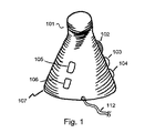
A computer pointing device 101 functions electronically as a mouse. The computer pointing device 101 preferably looks like a standing hawk's head. The computer pointing device 101 allows operations such as moving the sensor, turning the scroll wheel 102 and clicking the buttons 103, 104, 105 while being ergonomically held by the entire palm in a natural upright position. .
Description
本出願は、人間工学的形状のコンピュータポインティング装置(ERGONOMICALLY SHAPED COMPUTER POINTING DEVICE)という名称にて2002年5月2日付けで出願された米国仮特許出願第60/376,877号の主体となるものである。 This application is the subject of US Provisional Patent Application No. 60 / 376,877 filed on May 2, 2002 under the name of ERONOMICALLY SHAPED COMPUTER POINTING DEVICE. It is.
本発明は、全体として、コンピュータポインティング装置、特に、人間工学的形状のコンピュータマウスに関する。 The present invention relates generally to computer pointing devices, and more particularly to an ergonomic computer mouse.
マウスは、ユーザが表面上にてポインティング装置を動かすことによりカーソルをコンピュータスクリーン上にて動かし、ボタンの1つを瞬間的にクリックして特定のプログラム化した命令を実行し、特定のドラッギング操作のためボタンの1つをクリックし且つ保持し、特定のウィンドウを便宜にスクロールするため選択的なスクロールホイールを回すことを可能にする一般的なコンピュータポインティング装置である。 The mouse moves the cursor on the computer screen as the user moves the pointing device over the surface, momentarily clicks one of the buttons to execute a specific programmed command, and performs a specific dragging operation. It is a common computer pointing device that allows you to click and hold one of the buttons to turn a selective scroll wheel to conveniently scroll through a particular window.
人間工学的であり且つ、反復運動(過多)損傷(Repetitive Strain Injury)、すなわちRSIを緩和するマウスを提供しようとする多くの試みが為されてきた。 Many attempts have been made to provide mice that are ergonomic and alleviate Repetitive Strain Injury, or RSI.
ゴードン(Gordon)による2001年8月2日付けの米国特許出願第US2001/0010515 A1号には、親指側とは反対側の掌隆起部と小指とが作業面上に置かれるような、自然で撓んでいない状態の手に形成されるU字形の開口部内にマウスがあるときに、親指とそれに対向した指との間の挟み動作により把持されることを許容する、人間工学的マウスが提案されている。 US Patent Application No. US2001 / 0010515 A1, dated August 2, 2001, by Gordon, is such that the palm ridge and little finger opposite the thumb side are placed on the work surface. An ergonomic mouse has been proposed that allows a mouse to be grasped by a pinching action between a thumb and an opposing finger when the mouse is in a U-shaped opening formed in an unflexed hand. ing.
3Mルネサンスマウス(Renaissance Mouse)(http://www.3m.com/cws/renmouse.html)は、傾斜したスティックの形状をしており、該スティックの頂部には2つのボタンが配置されている。 The 3M Renaissance Mouse (http://www.3m.com/cws/renmouse.html) has an inclined stick shape with two buttons on the top of the stick. .
エドワーズ(Edwards)らにより人間工学的コンピュータマウス(Ergonomic Computer Mouse)として2002年3月26日付けで出願された米国特許第6,362,811号は、マウスの表面を水平面から約50°傾斜させることを提案している。 US Pat. No. 6,362,811, filed March 26, 2002 by Edwards et al. As an ergonomic computer mouse, tilts the surface of the mouse about 50 ° from the horizontal plane. Propose that.
ロー(Lo)らにより人間工学的コンピュータマウス(Ergonomic Computer Mouse)として1996年11月19日付けで出願された米国特許第5,576,733号も、傾斜したマウス表面を提案している。 US Pat. No. 5,576,733, filed November 19, 1996 as an ergonomic computer mouse by Lo et al. Also proposes an inclined mouse surface.
ソイヤー(Sawyer)により人間工学的コンピュータマウス(Ergonomic Computer Mouse)として2001年7月17日付けで出願された米国特許第6,262,715号は、ボタンのクリック動作を行うためのアーム伸長部を有する立ち上り基部を提案している。 US Pat. No. 6,262,715, filed July 17, 2001 as an ergonomic computer mouse by Sawyer, has an arm extension for performing a button click action. Proposes a rising base with.
バー(Barr)によりコンピュータマウス及び殻体(Computer Mouse and Shell)として1999年4月13日付けで出願された米国特許第5,894,303号は、捻ったカップのようにして保持される形状体を提案している。 U.S. Pat. No. 5,894,303, filed April 13, 1999 as a computer mouse and shell by Barr, has a shape held like a twisted cup. Suggest body.
本発明は、指が自然に曲がった状態にて、全ての指、掌内面及び掌底面に対して完全な支持を与えることによって、従来技術の人間工学的マウス以上の優れた人間工学的特徴を提供するものである。本発明は、親指及び人指し指の組み合さった引っかけ動作によりマウスを持ち上げることも容易にする。 The present invention provides superior ergonomic features over prior art ergonomic mice by providing full support to all fingers, palm inner surface and palm bottom with the fingers naturally bent. It is to provide. The present invention also facilitates lifting the mouse by a combined hooking action of the thumb and index finger.
ボタン及びスクロールホイールは、全体表面からの突出部を有し、これらには、従来技術におけるように指先端表面ではなくて指の内側関節面が接触するような設計とされている。本発明は、指がボタンをクリックするか又はスクロールホイールを回すとき、指が掌に向けて内方に曲げ動作することを許容する。 The buttons and scroll wheel have protrusions from the entire surface that are designed to contact the inner articular surface of the finger rather than the finger tip surface as in the prior art. The present invention allows the finger to bend inward toward the palm when the finger clicks the button or turns the scroll wheel.
更に、本発明は、親指又はその他の指の関節の内側が側方向へ擦り動作することによりスクロールホイールを回すことも許容する。
本発明は、小指及び掌隆起部が半ば作業面に楽に置かれるとともに、半ば装置の基部に押し付けられることを許容する。
Furthermore, the present invention also allows the scroll wheel to be turned by rubbing the inside of the thumb or other finger joints in the lateral direction.
The present invention allows the little finger and palm ridge to be comfortably placed on the mid-work surface and pressed against the base of the mid-device.
全体として、本発明は、広範囲な手の大きさ及び掌の大きさに対して柔軟に適合することを可能にする。
ここに示す全ての有利な効果は、ユーザに対して十分に人間工学的であるコンピュータポインティング操作を可能とし、長時間、肉体的支障なく使用することを可能にする。
Overall, the present invention allows flexible adaptation to a wide range of hand sizes and palm sizes.
All the advantageous effects shown here enable a computer pointing operation that is sufficiently ergonomic for the user and allows it to be used for long periods of time without physical problems.
要約すれば、形状体の顕著な特徴は、1)前腕の方向とほぼ整合した長軸線を有するほぼ長円形の基部、2)保持したときに掌に嵌まる、基部の上方に立つ円錐体、3)前面に向けて傾く頂部先端、4)ユーザの指の関節に対し都合良く近接して位置づけられているボタン及びスクロールホイールを含む。 In summary, the prominent features of the shape are: 1) a generally oval base having a major axis that is generally aligned with the direction of the forearm, 2) a cone standing above the base that fits in the palm when held. 3) Top tip tilted towards the front, 4) Button and scroll wheel positioned conveniently close to the user's finger joint.
該形状体は、次のことを含む仕方にて人間工学的コンピュータポインティングの操作を向上させる、すなわち、1)手が自然の直立の位置を維持することを許容すること、2)掌の全体が装置を保持する間、5本の指の全てが自然に内方に曲がるのを許容すること、3)小指及び掌の基部が、半分は作業面上に休止し、半分は装置の基部に対して押し付けられることを許容すること、4)親指及びその他の指の最外側の関節によりボタンのクリック動作及びスクロールホイールを回す動作を行うこと、5)親指の指関節(ナックル)の内側を側方向へ擦る動作により親指でスクロールホイールを回すこと、6)ボタンをクリックすること、および、スクロールホイールを回すことが、指が掌に向けて内方に曲がる動作を促進すること、7)親指及び人指し指による自然な引っかけおよび保持作用によって容易に持ち上げられること、8)手又は掌のサイズが広範囲にわたっても、それぞれの5本の指全て及び掌面に対して融通のきく適合状態及び支持状態が得られること、を含む。 The shape enhances ergonomic computer pointing operations in a manner that includes the following: 1) allows the hand to maintain a natural upright position, 2) the entire palm Allow all five fingers to bend inward naturally while holding the device 3) The little finger and palm base rest on the work surface, half against the base of the device 4) Clicking the button and turning the scroll wheel with the outermost joint of the thumb and other fingers 5) Performing the lateral movement inside the thumb joint (knuckle) Rotate the scroll wheel with your thumb by rubbing, 6) Clicking the button, and turning the scroll wheel promote the movement of the finger inward toward the palm, 7) Parent And easily lifted by the natural hooking and holding action of the forefinger, and 8) flexible fit and support for all five fingers and the palm surface, even over a wide range of hand or palm sizes. Obtained.
本発明の上記及びその他の目的、有利な効果及び特徴は、以下の説明及び添付図面を検討することにより、一層明らかになるであろう。 The above and other objects, advantageous effects and features of the present invention will become more apparent by examining the following description and the accompanying drawings.
本発明を具体化する、人間工学的形状のコンピュータポインティング装置は、図1ないし図8に色々な角度にて、及び操作者の手を示し又は示さずに図示されている。コンピュータポインティング装置としての本発明の電気的機能は、現代のコンピュータマウスのものと同一である。すなわち、ユーザがカーソルをモニター又はディスプレイ(図示せず)上にて動かし、スクロールホイールを回し、コンピュータと相互作用するのに必要な動作として色々なボタンをクリックすることを許容する。したがって、これらの電気的な特徴について説明する必要はない。 An ergonomic computer pointing device embodying the present invention is illustrated in FIGS. 1-8 at various angles and with or without an operator's hand. The electrical function of the present invention as a computer pointing device is the same as that of a modern computer mouse. That is, the user is allowed to move the cursor on a monitor or display (not shown), turn the scroll wheel, and click on various buttons as necessary to interact with the computer. Therefore, it is not necessary to explain these electrical features.
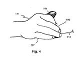
ポインティング装置101は、右利き型として示され、ポインティング装置113は、左利き型として示されている。両手利き型式のもの、すなわち何れの手でも使用できるものを設計することも完全に具体化可能である。
The
ポインティング装置の左側部のネック部付近に配置されたスクロールホイール102は、接触及び擦り領域として内側関節108を使用して親指により操作する。親指は、スクロールホイールを動かすように側方向への動きをもって動く。ポインティング装置の左側部に沿って配置されたボタン103、104は、親指の内側関節108による押し付け動作にて操作する設計とされている。ボタン104は、簡略化した設計のものにおいてはオプション品とすることができる。異なる実施の形態においては、スクロールホイール102及びボタン103、104の位置は互いに交換することができる。
A
ボタン105、106は、便宜に右手で(又は、それぞれ、左手で)操作し得るように中心線から僅かに離れて、ポインティング装置の前方部に配置されている。
ボタン105、106は、簡略化した設計のものにおいてはオプション品とすることができる。
The
電気コード112は、コンピューティングシステムにポインティング装置を接続する。コンピューティングシステムは、パーソナルコンピュータ、ゲーミングコンソール、又はポインティング装置の入力を利用することのできる任意の他の電子装置を含む。ワイヤーレス方式の実施の形態においては、コード112は存在せず、その機能は、高周波、光学、音波又はその他の任意の可能なインターフェース媒体により置換される。
The
ポインティング装置の先端は、その機能および形態に即して前方に傾いた設計とされている。ポインティング装置の機能とは、把持する手によって把持しやすく且つ持ち上げやすいということである。例えば、ポインティング装置の有用性を犠牲にすることなく、先端の形状をキノコの頂部のように変化させることも実現可能である。 The tip of the pointing device is designed to tilt forward in accordance with its function and form. The function of the pointing device is that it is easy to grip and lift by the gripping hand. For example, it is possible to change the shape of the tip like the top of a mushroom without sacrificing the usefulness of the pointing device.
ポインティング装置の図8に示した底面図から見たときの基部116は、ほぼ長円形の形状をしており、その長軸線は前腕の方向と整列している。より正確に説明すれば、この形状体は前方部に小端を有する西洋梨状の形状体である。参照番号117が示すのは、X−Y動作を感知し得るための可動ボール又は光センサを配置し得るところの、ポインティング装置の底部116のおおよその位置である。基部縁部107は、小指及び掌の基部が作業面と接触し且つその作業面に対し摺動するのを許容する一方にて、それと同時に小指及び掌の基部が基部縁部107に密着することを許容する。掌及び指を含む手は、図3に示すようにポインティング装置と楽に完全に接触する。接触領域110は、ポインティング装置と親指及び人指し指により形成されたU字形部分との間の接触領域である。参照番号108は、親指とポインティング装置との間の中央接触領域を示す。接触領域107は、小指及び掌の基部に対するものである。図面に図示しない全体の内側掌も、ポインティング装置の面と全体的に接触する。これは、手及び前腕に対して極めて自然な直立で且つ人間工学的な位置である。ポインティング装置の主要な円錐面は、基部116に対する絶対的な直立位置から約20°ないし45°だけ前方に傾いている。この輪郭外形は図1の正面図、図2の側面図及び図5の頂面図に明確に示されている。
When viewed from the bottom view shown in FIG. 8 of the pointing device, the
図6及び図7には、参照番号114で示すようなボタン及びスクロールホイール115が鏡像の配置状態にある左利き型の実施の形態が示されている。両手利き型である実施の形態を設計することも完全に具体化可能である。例えば、スクロールホイールを交換可能にするか又は各側部に1つずつ、2つのスクロールホイールを有するようにすることもできる。
6 and 7 show a left-handed embodiment in which the button and
スクロールホイール及びボタンが作動されるとき、関節を内方に曲げるようにして指が鈎(かぎ)状になる動作をして係合することも重要である。
要するに、ポインティング装置の人間工学的特徴は、1)手が操作の全般に亙って自然の垂直位置を維持することを許容すること、2)掌の全体が装置を保持する一方で、5つの指の全てを自然に内方に曲げることを許容すること、3)小指及び掌の基部が半分、作業面上に休止し、半分、装置の基部に対し押し付けられることを許容すること、4)ユーザが指先端ではなくて、親指及びその他の指の第一関節を押し付けることによりボタン及びスクロールホイールを作動させることを許容すること、5)ボタン及びスクロールホイールを作動させることが、指を掌の方に向けて内方に鈎状になる動作することを促進すること、6)広範囲にわたる手又は掌のサイズに適合すること、を含む。
When the scroll wheel and button are actuated, it is also important that the fingers be engaged like a hook by bending the joints inward.
In short, the ergonomic features of the pointing device are: 1) allowing the hand to maintain a natural vertical position throughout the operation, 2) while the entire palm holds the device, Allow all fingers to bend inward naturally 3) Allow the little finger and palm base to rest on the work surface in half and half to be pressed against the base of the device 4) Allowing the user to actuate the button and scroll wheel by pressing the first joint of the thumb and other fingers instead of the fingertip, 5) actuating the button and scroll wheel, Facilitating an inwardly wrinkling action toward the direction, 6) adapting to a wide range of hand or palm sizes.
ポインティング装置の底部又は内部に取り付けられた標準型の転がるボール117又は光センサ又はジャイロスコープセンサ117Aの何れかにより、コンピューティング装置内でのカーソルのX−Y方向への動きが実現される。手は、ポインティング装置を自然で且つほぼ直立の位置に保持しつつ、X−Y方向への動きを実現する。これは、最初の習熟化ステップの後に適応容易なスタイルの操作である。
Movement of the cursor in the XY direction within the computing device is accomplished by either a
ユーザがポインティング装置を表面に押しつけながら動かすことを必要とせずに自由空間内でX−Y方向への動きを実現することを許容する、ワイヤーレスの入力装置としてポインティング装置を具体化することも可能である。上述したように、左方から右方向への回転をX方向への動きに変換し、また、前方から後方への回転をY方向への動きに変換するため、ジャイロスコープを使用することも可能である。 It is also possible to embody the pointing device as a wireless input device that allows the user to achieve movement in the XY direction in free space without having to move the pointing device against the surface. It is. As mentioned above, a gyroscope can also be used to convert left-to-right rotation into X-direction motion and forward-to-backward rotation into Y-direction motion. It is.
補助的に使用するため、追加のボタン及びスクローリングホイールをポインティング装置に取り付けることができる。
例えば、スクローリングホイールは、人指し指又は中指にてスクロールするため、ポインティング装置の前方にあるようにすることができる。
Additional buttons and scrolling wheels can be attached to the pointing device for auxiliary use.
For example, the scrolling wheel may be in front of the pointing device for scrolling with the index or middle finger.
別の実施の形態は、1つ又は1対のポインティング装置のハンドルから成るQWERTキーボードであり、このハンドルにはキーが配置されており、手を自然の直立位置に保ちつつ、指がこれらのキーにてタイプ打ちできるようになっている。更なる実施の形態は、かかるキーボード及び本発明のポインティング装置の組み合わせ体である。 Another embodiment is a QWERT keyboard consisting of one or a pair of pointing device handles, with keys arranged on the handles so that the fingers can hold these keys while keeping the hand in a natural upright position. It can be typed at. A further embodiment is a combination of such a keyboard and the pointing device of the present invention.
本発明は、本発明の好ましい実施の形態に関して説明したが、本発明のその他の実施の形態、適応及び変更実施形態は、当該技術分野の当業者に明らかであることが理解されよう。 Although the invention has been described with reference to preferred embodiments of the invention, it will be understood that other embodiments, adaptations and modifications of the invention will be apparent to those skilled in the art.
Claims (18)
作業面上に着座し且つ該作業面上を平行移動可能とするための全体的に平坦な底面と、
基部から上方に立ち上がる、全体として前方に傾いている円錐体と、
該円錐体よりも更に前方に傾くようにして該円錐体の頂部から伸びる先端と、
適正な突き出し程度にて前記円錐体の表面に配置された複数のボタンと、を備え、
該ボタン及びスクロールホイールが、操作の際に親指及びその他の指の複数の関節又は関節付近の領域によりそれぞれ押され又は擦られるようになされている、人間工学的コンピュータポインティング装置。 In ergonomic computer pointing device,
A generally flat bottom surface for sitting on the work surface and allowing translation on the work surface;
A cone that rises upward from the base and leans forward as a whole;
A tip extending from the top of the cone so as to tilt further forward than the cone;
A plurality of buttons arranged on the surface of the cone with a proper protruding degree,
An ergonomic computer pointing device wherein the buttons and scroll wheel are adapted to be pushed or rubbed by a plurality of joints or areas near the joints of the thumb and other fingers, respectively, during operation.
Applications Claiming Priority (3)
| Application Number | Priority Date | Filing Date | Title |
|---|---|---|---|
| US37687702P | 2002-05-02 | 2002-05-02 | |
| US10/411,287 US6954198B2 (en) | 2002-05-02 | 2003-04-11 | Ergonomically shaped computer pointing device |
| PCT/US2003/012119 WO2003094139A1 (en) | 2002-05-02 | 2003-05-02 | Ergonomically shaped computer pointing device |
Publications (2)
| Publication Number | Publication Date |
|---|---|
| JP2005524897A true JP2005524897A (en) | 2005-08-18 |
| JP2005524897A5 JP2005524897A5 (en) | 2006-06-22 |
Family
ID=29273077
Family Applications (1)
| Application Number | Title | Priority Date | Filing Date |
|---|---|---|---|
| JP2004502274A Pending JP2005524897A (en) | 2002-05-02 | 2003-05-02 | Ergonomic computer pointing device |
Country Status (7)
| Country | Link |
|---|---|
| US (1) | US6954198B2 (en) |
| EP (1) | EP1500073A4 (en) |
| JP (1) | JP2005524897A (en) |
| CN (1) | CN1656527A (en) |
| AU (1) | AU2003221719A1 (en) |
| TW (1) | TWI291120B (en) |
| WO (1) | WO2003094139A1 (en) |
Families Citing this family (14)
| Publication number | Priority date | Publication date | Assignee | Title |
|---|---|---|---|---|
| CN1692401B (en) * | 2002-04-12 | 2011-11-16 | 雷斯里·R·奥柏梅尔 | Multi-axis transducer means and joystick |
| JP2004029865A (en) * | 2002-06-03 | 2004-01-29 | Kokuyo Co Ltd | Mouse |
| JP4794801B2 (en) * | 2002-10-03 | 2011-10-19 | ルネサスエレクトロニクス株式会社 | Display device for portable electronic device |
| NL1022328C2 (en) * | 2003-01-08 | 2004-07-09 | Tensor B V | Operating device for a computer. |
| US20090213068A1 (en) * | 2004-06-14 | 2009-08-27 | Humanscale Corporation | Ergonomic Pointing Device |
| AT7780U1 (en) * | 2004-09-01 | 2005-08-25 | Stefan Krichbaum | COMPUTER MOUSE |
| US7773074B2 (en) * | 2005-06-28 | 2010-08-10 | Siemens Medical Solutions Usa, Inc. | Medical diagnostic imaging three dimensional navigation device and methods |
| US9098122B2 (en) * | 2007-12-12 | 2015-08-04 | The Charles Stark Draper Laboratory, Inc. | Computer input device with inertial instruments |
| DE102008017832B4 (en) * | 2008-04-08 | 2011-06-16 | Siemens Aktiengesellschaft | Input device for controlling elements of graphic user interfaces |
| TWI361992B (en) * | 2008-06-13 | 2012-04-11 | Avermedia Information Inc | Wireless control device and multi-cursor control method |
| US9092073B1 (en) * | 2010-05-11 | 2015-07-28 | Contour Design, Inc. | Adjustable pointing device |
| US9785256B2 (en) * | 2015-02-16 | 2017-10-10 | Ming Xia | Ergonomic computer mouse with handheld and ambidextrous body design |
| WO2018175054A1 (en) * | 2017-03-21 | 2018-09-27 | Ko Tony Chun Te | Single finger multiple finger segments triggering mechanism |
| US10088918B1 (en) * | 2017-05-07 | 2018-10-02 | Jack Lo | Ergonomic computer mouse |
Family Cites Families (15)
| Publication number | Priority date | Publication date | Assignee | Title |
|---|---|---|---|---|
| US5440326A (en) * | 1990-03-21 | 1995-08-08 | Gyration, Inc. | Gyroscopic pointer |
| US5576733A (en) * | 1994-05-25 | 1996-11-19 | Lo; Jack | Ergonomic computer mouse |
| US5648798A (en) * | 1995-02-13 | 1997-07-15 | Hamling; Daniel T. | Universal ergonomic computer mouse/trackball |
| US5894303A (en) * | 1995-03-14 | 1999-04-13 | Barr; Ann E. | Computer mouse and shell therefore |
| US6362811B1 (en) | 1996-02-20 | 2002-03-26 | George Neil Edwards | Ergonomic computer mouse |
| WO1998006025A1 (en) * | 1996-08-01 | 1998-02-12 | Krog Gabriel Wergeland | Device for operating of a mouse-operated data program |
| US6577298B2 (en) * | 1996-08-01 | 2003-06-10 | Gabriel Wergeland Krog | Device for operating a mouse-operated computer program |
| US6128006A (en) * | 1998-03-26 | 2000-10-03 | Immersion Corporation | Force feedback mouse wheel and other control wheels |
| FR2767397B3 (en) * | 1997-08-18 | 1999-07-23 | Kuo Shu Cheng | MULTI-AXIS SIGNAL INPUT DEVICE OF A MOUSE |
| US6072471A (en) * | 1997-09-17 | 2000-06-06 | Lo; Jack | Ambidextrous upright computer mouse |
| US6396479B2 (en) | 1998-07-31 | 2002-05-28 | Agilent Technologies, Inc. | Ergonomic computer mouse |
| DE19901861A1 (en) * | 1999-01-19 | 2000-07-20 | Ulrich Schmidt | Computer mouse has rearward declining lateral grip surface of housing with essentially shape of at least one section of spherical casing with apex angle of no greater than 40 degrees. |
| US6262715B1 (en) * | 1999-02-05 | 2001-07-17 | Lucent Technologies, Inc. | Ergonomic computer mouse |
| US6377245B1 (en) * | 1999-09-02 | 2002-04-23 | Chin K. Park | Ultimate ergonomic mouse |
| EP1182606A2 (en) * | 2000-07-31 | 2002-02-27 | Agilent Technologies, Inc. (a Delaware corporation) | Four axis optical mouse |
-
2003
- 2003-04-11 US US10/411,287 patent/US6954198B2/en not_active Expired - Fee Related
- 2003-05-02 JP JP2004502274A patent/JP2005524897A/en active Pending
- 2003-05-02 CN CNA038098938A patent/CN1656527A/en active Pending
- 2003-05-02 TW TW092112108A patent/TWI291120B/en not_active IP Right Cessation
- 2003-05-02 WO PCT/US2003/012119 patent/WO2003094139A1/en active Application Filing
- 2003-05-02 AU AU2003221719A patent/AU2003221719A1/en not_active Abandoned
- 2003-05-02 EP EP03718456A patent/EP1500073A4/en not_active Withdrawn
Also Published As
| Publication number | Publication date |
|---|---|
| US20030206152A1 (en) | 2003-11-06 |
| EP1500073A1 (en) | 2005-01-26 |
| US6954198B2 (en) | 2005-10-11 |
| WO2003094139A1 (en) | 2003-11-13 |
| EP1500073A4 (en) | 2008-10-01 |
| CN1656527A (en) | 2005-08-17 |
| TWI291120B (en) | 2007-12-11 |
| TW200400458A (en) | 2004-01-01 |
| AU2003221719A1 (en) | 2003-11-17 |
Similar Documents
| Publication | Publication Date | Title |
|---|---|---|
| AU2004303361B2 (en) | Hand manipulated data apparatus for computers and video games | |
| CA2529466C (en) | Ergonomic pointing device | |
| US20020171625A1 (en) | Pistol-grip trackball mouse | |
| US8022930B2 (en) | Ergonomic input device | |
| JP2005524897A (en) | Ergonomic computer pointing device | |
| US6292175B1 (en) | Ergonomic trackball device | |
| JP2005524897A5 (en) | ||
| US20090213068A1 (en) | Ergonomic Pointing Device | |
| US6680728B1 (en) | Cursor control device for convenient and ergonomic hand-held or work-surface use | |
| US20050030288A1 (en) | Portable and ergonomic computer input device | |
| KR100354970B1 (en) | Mouse apparatus for use computer | |
| US11256345B2 (en) | Hand operated computer input device with palm heel support | |
| JP2021099738A (en) | Mouse device | |
| WO2000029933A1 (en) | Ergonomic computer mouse | |
| US20060176268A1 (en) | Device for inputting control signals to a peripheral unit and a combination including such a device | |
| KR101090424B1 (en) | Mouse for computer | |
| JP4936143B2 (en) | Computer mouse | |
| JP2018032103A (en) | mouse | |
| JP2001243013A (en) | Mouse to be gripped only with tip of finger so as to be operated and wrist placing stand for reducing load of wrist | |
| KR200244385Y1 (en) | Pointing device | |
| EP4127881A1 (en) | Computer mouse | |
| JP2009020875A5 (en) | ||
| KR20070095046A (en) | Mouse for computer | |
| KR200324953Y1 (en) | Pad-mouse | |
| KR200360662Y1 (en) | The mouse |
Legal Events
| Date | Code | Title | Description |
|---|---|---|---|
| A521 | Written amendment |
Free format text: JAPANESE INTERMEDIATE CODE: A523 Effective date: 20060502 |
|
| A621 | Written request for application examination |
Free format text: JAPANESE INTERMEDIATE CODE: A621 Effective date: 20060502 |
|
| A131 | Notification of reasons for refusal |
Free format text: JAPANESE INTERMEDIATE CODE: A131 Effective date: 20080808 |
|
| A02 | Decision of refusal |
Free format text: JAPANESE INTERMEDIATE CODE: A02 Effective date: 20090120 |