JP2005500725A - Electronic article comprising a loudspeaker and a touchpad - Google Patents
Electronic article comprising a loudspeaker and a touchpad Download PDFInfo
- Publication number
- JP2005500725A JP2005500725A JP2003514489A JP2003514489A JP2005500725A JP 2005500725 A JP2005500725 A JP 2005500725A JP 2003514489 A JP2003514489 A JP 2003514489A JP 2003514489 A JP2003514489 A JP 2003514489A JP 2005500725 A JP2005500725 A JP 2005500725A
- Authority
- JP
- Japan
- Prior art keywords
- transducer
- touchpad
- resonant element
- resonant
- mode
- Prior art date
- Legal status (The legal status is an assumption and is not a legal conclusion. Google has not performed a legal analysis and makes no representation as to the accuracy of the status listed.)
- Abandoned
Links
Images


Classifications
-
- H—ELECTRICITY
- H04—ELECTRIC COMMUNICATION TECHNIQUE
- H04R—LOUDSPEAKERS, MICROPHONES, GRAMOPHONE PICK-UPS OR LIKE ACOUSTIC ELECTROMECHANICAL TRANSDUCERS; DEAF-AID SETS; PUBLIC ADDRESS SYSTEMS
- H04R7/00—Diaphragms for electromechanical transducers; Cones
- H04R7/02—Diaphragms for electromechanical transducers; Cones characterised by the construction
- H04R7/04—Plane diaphragms
- H04R7/045—Plane diaphragms using the distributed mode principle, i.e. whereby the acoustic radiation is emanated from uniformly distributed free bending wave vibration induced in a stiff panel and not from pistonic motion
-
- G—PHYSICS
- G06—COMPUTING; CALCULATING OR COUNTING
- G06F—ELECTRIC DIGITAL DATA PROCESSING
- G06F1/00—Details not covered by groups G06F3/00 - G06F13/00 and G06F21/00
- G06F1/16—Constructional details or arrangements
- G06F1/1613—Constructional details or arrangements for portable computers
- G06F1/1615—Constructional details or arrangements for portable computers with several enclosures having relative motions, each enclosure supporting at least one I/O or computing function
- G06F1/1616—Constructional details or arrangements for portable computers with several enclosures having relative motions, each enclosure supporting at least one I/O or computing function with folding flat displays, e.g. laptop computers or notebooks having a clamshell configuration, with body parts pivoting to an open position around an axis parallel to the plane they define in closed position
-
- G—PHYSICS
- G06—COMPUTING; CALCULATING OR COUNTING
- G06F—ELECTRIC DIGITAL DATA PROCESSING
- G06F1/00—Details not covered by groups G06F3/00 - G06F13/00 and G06F21/00
- G06F1/16—Constructional details or arrangements
- G06F1/1613—Constructional details or arrangements for portable computers
- G06F1/1626—Constructional details or arrangements for portable computers with a single-body enclosure integrating a flat display, e.g. Personal Digital Assistants [PDAs]
-
- G—PHYSICS
- G06—COMPUTING; CALCULATING OR COUNTING
- G06F—ELECTRIC DIGITAL DATA PROCESSING
- G06F1/00—Details not covered by groups G06F3/00 - G06F13/00 and G06F21/00
- G06F1/16—Constructional details or arrangements
- G06F1/1613—Constructional details or arrangements for portable computers
- G06F1/1633—Constructional details or arrangements of portable computers not specific to the type of enclosures covered by groups G06F1/1615 - G06F1/1626
- G06F1/1684—Constructional details or arrangements related to integrated I/O peripherals not covered by groups G06F1/1635 - G06F1/1675
- G06F1/1688—Constructional details or arrangements related to integrated I/O peripherals not covered by groups G06F1/1635 - G06F1/1675 the I/O peripheral being integrated loudspeakers
-
- G—PHYSICS
- G06—COMPUTING; CALCULATING OR COUNTING
- G06F—ELECTRIC DIGITAL DATA PROCESSING
- G06F1/00—Details not covered by groups G06F3/00 - G06F13/00 and G06F21/00
- G06F1/16—Constructional details or arrangements
- G06F1/1613—Constructional details or arrangements for portable computers
- G06F1/1633—Constructional details or arrangements of portable computers not specific to the type of enclosures covered by groups G06F1/1615 - G06F1/1626
- G06F1/1684—Constructional details or arrangements related to integrated I/O peripherals not covered by groups G06F1/1635 - G06F1/1675
- G06F1/169—Constructional details or arrangements related to integrated I/O peripherals not covered by groups G06F1/1635 - G06F1/1675 the I/O peripheral being an integrated pointing device, e.g. trackball in the palm rest area, mini-joystick integrated between keyboard keys, touch pads or touch stripes
-
- G—PHYSICS
- G06—COMPUTING; CALCULATING OR COUNTING
- G06F—ELECTRIC DIGITAL DATA PROCESSING
- G06F3/00—Input arrangements for transferring data to be processed into a form capable of being handled by the computer; Output arrangements for transferring data from processing unit to output unit, e.g. interface arrangements
- G06F3/01—Input arrangements or combined input and output arrangements for interaction between user and computer
- G06F3/03—Arrangements for converting the position or the displacement of a member into a coded form
- G06F3/033—Pointing devices displaced or positioned by the user, e.g. mice, trackballs, pens or joysticks; Accessories therefor
- G06F3/0354—Pointing devices displaced or positioned by the user, e.g. mice, trackballs, pens or joysticks; Accessories therefor with detection of 2D relative movements between the device, or an operating part thereof, and a plane or surface, e.g. 2D mice, trackballs, pens or pucks
- G06F3/03547—Touch pads, in which fingers can move on a surface
-
- G—PHYSICS
- G06—COMPUTING; CALCULATING OR COUNTING
- G06F—ELECTRIC DIGITAL DATA PROCESSING
- G06F2200/00—Indexing scheme relating to G06F1/04 - G06F1/32
- G06F2200/16—Indexing scheme relating to G06F1/16 - G06F1/18
- G06F2200/163—Indexing scheme relating to constructional details of the computer
- G06F2200/1634—Integrated protective display lid, e.g. for touch-sensitive display in handheld computer
Abstract
電子物品(190)で使用するためのタッチパッド組立体(202)であり、該タッチパッド組立体は、タッチパッド(202)と、該タッチパッド(202)を電子物品のケーシング(198)に機械的に結合するためのカプラと、結合手段(66)によってカプラ又はタッチパッド上に取り付けられケーシングを音響ラジエータとして駆動する変換器(108)とを備える。電子物品は同様のものを組み込んでいる。電子物品(190)は、内部又はその上に撓み波ラウドスピーカが取り付けられた本体を備え、ラウドスピーカが撓み波音響ラジエータ(204)と、ラジエータ(204)に取り付けられ該ラジエータを振動させて音響出力を生成する電気機械式力変換器(108)とを有し、変換器(108)は、意図された作動周波数領域を有し、該作動周波数領域のモードの周波数分布を有する共振素子と、変換器(108)をラジエータに取り付ける結合手段(66)とが設けられている。
【選択図】図7A touchpad assembly (202) for use in an electronic article (190), wherein the touchpad assembly is a machine for placing the touchpad (202) and the touchpad (202) in a casing (198) of the electronic article. And a transducer (108) mounted on the coupler or touchpad by a coupling means (66) to drive the casing as an acoustic radiator. The electronic article has incorporated the same thing. The electronic article (190) includes a main body in which a bending wave loudspeaker is attached or on the inside thereof. The loudspeaker is attached to the bending wave acoustic radiator (204) and the radiator (204), and the radiator is vibrated to generate sound. An electromechanical force transducer (108) that produces an output, the transducer (108) having a intended operating frequency range and a resonant element having a frequency distribution of modes in the operating frequency range; Coupling means (66) is provided for attaching the converter (108) to the radiator.
[Selection] Figure 7
Description
【技術分野】
【0001】
本発明は電子物品に関し、より詳細には例えば、携帯電話、個人用管理手帳、及びポケットラジオのような個人用途の電子物品などの、低出力の又は電力自給式の物品に関する。
【背景技術】
【0002】
国際特許出願WO00/69212により、内部又はその上に撓み波ラウドスピーカが装着された本体又はケーシングを有する個人用の携帯型電子物品が提供されることが知られている。撓み波ラウドスピーカは、音響ラジエータと、ラジエータに取り付けられ該ラジエータを振動させて音響出力を生成する振動励振器とを備える。ラジエータは射出成形によって本体又はケーシングと一体成形され、本体又はケーシングの副領域を定める。個人用の携帯型電子物品とは手持ちできるほど十分小さい物品を意味する。
【0003】
ラジエータは国際特許出願WO97/09842に記載された種類の分布モード音響ラジエータスピーカとすることができる。
【0004】
一般に、個人用の携帯型電子物品は低出力装置又は電力自給式装置のいずれかである。
【0005】
【特許文献1】
国際特許出願WO00/69212公報
【特許文献2】
国際特許出願WO97/09842公報
【発明の開示】
【課題を解決するための手段】
【0006】
本発明によれば、電子物品は撓み波ラウドスピーカが内部又はその上に装着された本体又はケーシングを備え、該ラウドスピーカが、撓み波音響ラジエータと、該ラジエータに取り付けられ該ラジエータを振動させて音響出力を生成する電気機械式力変換器とを備え、該変換器は、意図された作動周波数領域を有し、かつ作動周波数領域のモードの周波数分布を有する共振素子と前記変換器をラジエータに取り付ける結合手段とが設けられている。該結合手段は前記共振素子に取り付けてもよい。
【0007】
電子物品は、例えば光又は赤外線電源のいずれかを備えた遠隔電源の物品でもよい。従って、電子物品は、無線パネル、個人用PA、又は太陽電池パネルから選択することができる。電子物品は、ポータブルラジオ、ウオークマン、個人用携帯型情報端末(PDA)、電子玩具、ブザー、ポリフォニック又はモノフォニック音響器、チャイム、電子ノベルティ、ラップトップ、コンピュータマウス、キーボード、ディスプレイケース、パーソナルコンピュータ、モニタ、又はテレビのような、例えばコードレス製品といった低出力物品でもよい。電子物品はまた、例えば使い捨てのスピーカ又はブザー、低コストの通信装置、クレジットカード、ノベルティ、本又はカードなどの使い捨てでもよい。
【0008】
音響ラジエータは、本体又はケーシングと共に成型すなわち一体成型することができる。ラジエータは透明にすることができ、例えばディスプレイスクリーンの領域を定めることができる。
【0009】
音響ラジエータはタッチパッドであってもよい。音響ラジエータは、タッチパッドを取り囲むケーシングの全体又は一部とすることができる。結合手段は、例えばタッチパッドの外周を取り囲んでいるフレームによりケーシングと音響的に結合されたタッチパッドを備えることができる。変換器は、タッチパッドに対してタッチパッド上に直接か、又はフレーム上のいずれかに取り付けることができ、変換器はケーシングを駆動する。タッチパッドは一体式固定クリップ、或いはボルト、ネジ、又は差し込み固定具などの別個の固定部品を使用してケーシングに結合することができる。或いは、タッチパッドはケーシングに摩擦係止することができる。
【0010】
このようにして、タッチパッド及び変換器を備える一体型組立体を使用して、音響ラジエータを駆動することができる。タッチパッド及び該タッチパッドを取り囲んでいるケーシングは、両方とも音響ラジエータとして機能し、ケーシングは第1の音響ラジエータとして機能する。必要であれば、少なくとも1つの変換器を追加して第1の音響ラジエータに取り付けることができる。タッチパッド組立体は、例えばラップトップ又は個人用携帯型情報端末などの任意の電子装置の標準的なタッチパッドと置き換えることができる。
【0011】
共振素子は、例えば圧電変換器とすることができ、及び圧電材料のストリップの形態とすることができる能動型であってもよい。或いは、共振素子は受動型であってもよく、変換器は、例えば可動コイル変換器などの、慣性式又は接地式の振動式変換器、アクチュエータ又は励振器である能動変換器を更に備えることができる。能動変換器は、曲げ又は捻れ変換器(例えばWO00/13464で教示された種類の)であってもよい。更に変換器は、ハイブリッド変換器を形成する、受動素子と能動素子の組み合わせを備えることができる。
【0012】
例えばラウドスピーカの音響ラジエータなどの構造体に力を印加するために、多くの変換器、励振器、又はアクチュエータ機構が開発されてきた。これらの変換器機構には、例えば可動コイル、可動磁石、圧電式又は磁気歪み式などの種々の形式がある。通常、コイル及び磁石式の変換器を使用する電気力学式スピーカは99%の入力エネルギが熱として損失するのに対して、圧電式変換器には僅か1%の損失とすることができる。従って、圧電式変換器はその高効率の理由から普及している。
【0013】
圧電式変換器には幾つかの問題があり、例えば、本質的に真鍮泊に匹敵するほど剛性が非常に高く、従って、音響ラジエータ、特に空気に対して適合させるのが難しい。変換器の剛性が高くなると基本共振モードの周波数が高周波側へと移動する。すなわち、該圧電変換器は2つの作動領域を有すると考えることができる。第1の作動領域は、変換器の基本共振周波数より低い領域である。これは「剛性制御」領域であり、ここでは周波数に伴って速度が上昇し、通常は出力応答を均等にする必要がある。これは利用可能な効率の損失につながる。第2の領域は、剛性領域を超える共振領域であり、共振が非常に激しいので一般には回避される。
【0014】
更に、一般的な教示は、変換器における共振を抑制することであるので、一般に圧電変換器は、変換器の基本共振周波数以下の範囲だけで使用される。圧電変換器が基本共振周波数を超える範囲で使用される場合、共振のピークを抑制するために制振を加える必要がある。
【0015】
圧電変換器に関する問題は、他の「スマートな」材料、すなわち磁気歪み、電気歪み、及びエレクトレット型の材料の変換器についても同様に当てはまる。例えば、Shinsei Corporationの欧州特許公開EP0993231A、Shinsei Corporationの欧州特許公開EP0881856A、Murata Manufacturing Co. Limitedの米国特許第4,593,160号、Sanyo Electric Co. Limitedの米国特許第4,401,857号、Altec Corporationの米国特許第4,481,663号、及びSawafujiの英国特許出願GB2,166,022Aに記載されたような、種々の圧電変換器が公知である。しかしながら、本発明の目的は改良された変換器を使用することである。
【0016】
本発明で使用される変換器は、意図的なモード変換器と考えることができる。結合手段は、インターフェースに対する共振素子のモード動作を結合するのに有利な位置で共振素子に取り付けることができる。共振素子の、例えばアスペクト比、撓み剛性、厚み及び寸法などのパラメータは、作動周波数領域における共振素子中のモード分布を向上させるように選択することができる。共振素子の撓み剛性と厚みは等方性又は異方性になるように選択することができる。撓み剛性及び/又は厚みは共振素子のモード分布を向上させるように選択することができる。例えばFEA又はモデル化を使用したコンピュータシミュレーションなどの解析を用いてパラメータを選択することができる。
【0017】
分布は、能動素子の第1のモードを対象の最低動作周波数に確実に近づけることによって向上させることができる。分布はまた、作動周波数領域のモードを確実に満足できる、すなわち高い密度にすることによって向上させることができる。モード密度は能動素子に対して、周波数に関し実質的に一定の有効平均力を与えるのに十分であるのが好ましい。良好なエネルギ伝達により、モード共振の効果的な平滑化を得ることができる。或いは又は追加として、共振撓み波モード周波数に関して実質的に均一に分布させることによって、すなわちモードの「集群」又は群化に起因する周波数応答のピークを平滑化することによってモード分布を向上させることができる。このような変換器は、分布モード変換器又はDMTとして知られている。
【0018】
このような意図されたモード、すなわち分布モード変換器は国際特許出願WO001/54450に記載されている。
【0019】
変換器は、各々がモード分布を有する複数の共振素子を備えることができ、共振素子のモードは、作動周波数領域にインターリーブして、装置全体として変換器のモード分布を向上させるように配置されている。共振素子は異なる基本周波数を有することができ、従って、共振素子の負荷、寸法、又は撓み波剛性などのパラメータは異なるものとすることができる。
【0020】
共振素子は、例えば共振素子間の一般に剛性のスタブ上に、接続手段によって任意の好都合の方法で共に結合することができる。共振素子は、変換器のモダリティを向上させ、及び/又は力が付与されるべき場所での結合を向上させる結合点で結合されるのが好ましい。接続手段のパラメータは、共振素子のモード分布を向上させるように選択することができる。共振素子は積み重ねて配置することができる。結合点は軸方向に位置合わせすることができる。
【0021】
共振素子はプレート形状、又は平面の外側に湾曲していてもよい。プレート形状の共振素子は、スロット又は切れ目が形成され、複合共振系を形成することができる。共振素子は、ビーム形、台形、超楕円形、又は略ディスク形であってもよい。若しくは、共振素子は矩形であってもよく、対称の短軸に沿った軸の周りで矩形の平面の外側に湾曲していてもよい。
【0022】
共振素子は、2つの実質的に直角な軸に沿ってモード性があってもよく、各軸が関係する基本周波数を有する。2つの基本周波数比は、モード分布が最適となるように、例えば9:7(1.286:1)に調整することができる。
【0023】
実施例として、そのようなモード変換器の構成は、以下のいずれかとすることができる。平坦な圧電ディスク、少なくとも2つ又は好適には少なくとも3つの平坦な圧電ディスクの組み合わせ、2つの同一の圧電ビーム、複数の同一圧電ビームの組み合わせ、湾曲した圧電プレート、複数の湾曲した圧電プレート又は2つの同一圧電ビームの組み合わせである。
【0024】
各共振素子のモード分布のインターリーブは、共振素子の周波数比、すなわち各々の共振素子の各々の基本共振周波数の周波数比を最適化することによって向上させることができる。従って、互いに関連する各共振素子のパラメータは、変換器の全体モード分布を向上させるように変更することができる。
【0025】
ビーム形状の2つの能動共振素子を使用する場合、2つのビームの周波数比(すなわち基本周波数比)は1.27:1とすることができる。3つのビームを有する変換器においては、周波数比は1.315:1.147:1とすることができる。2つのディスクを有する変換器においては、高次モード密度を最適化する周波数比は1.1+/−0.02:1とすることができ、低次モード密度を最適化する周波数比は3.2:1とすることができる。3つのディスクを有する変換器においては、周波数比は3.03:1.63:1、又は8.19:3.20:1とすることができる。
【0026】
結合手段のパラメータは、作動周波数領域の共振素子のモード分布を向上させるように選択することができる。結合手段は、例えば制御された接着層などの痕跡とすることができる。
【0027】
結合手段は、変換器が非対称に結合されるように、パネルに対して非対称に配置することができる。例えば、パネル又は変換器の対称軸に対する変換器の位置又は配向を調整するなどの幾つかの方法で非対称を実現することができる。
【0028】
結合手段は取付ラインを形成することができる。或いは結合手段は、共振素子の寸法に対して取付の領域が小さい場合、取付点又は小さな局所的領域を形成することができる。結合手段は、スタブの形態であってもよく、例えば3乃至4mmの小さな直径とすることができる。結合手段は低質量とすることができる。
【0029】
結合手段は、2つ以上の結合点を備えることができ、取付点及び/又は取付ラインの組合せを備えることができる。例えば、2つの取付点又は小さな局所的取付領域が使用でき、1つは能動素子の中心近傍に、1つは能動素子の端部に配置される。これは、一般に剛性があり固有共振周波数が高いプレート形状変換器にとって有用である。
【0030】
或いは、単一の結合点だけを提供することもできる。これは、複合共振素子アレイの場合に利点をもたらすことができ、すべての共振素子の出力が単一の結合手段により合計され、その結果、負荷によって出力を合計することは不要である。結合手段は、共振素子上のアンチノードに配置されるように選択することができ、周波数に関して一定の平均力を与えるように選択することができる。結合手段は共振素子の中心から離して配置することができる。
【0031】
取付ラインの位置及び/又は配向は、共振素子のモード密度を最適化するように選択することができる。取付ラインは、共振素子の対称線とは一致しないことが好ましい。例えば、矩形の共振素子においては、取付ラインは共振素子の対称短軸(すなわち中心線)からオフセットすることができる。取付ラインはパネルの対称軸に対して平行ではない配向とすることができる。
【0032】
共振素子の形状は、共振素子のほぼ質量中心にあり、中心を外れた取付ラインをもたらすように選択することができる。この実施形態の1つの利点は、変換器がその質量中心に取り付けられるので慣性的な不均衡がないことである。これは不等辺四辺形すなわち台形である非対称形状の共振素子によって達成することができる。
【0033】
ビーム形状又は略矩形の共振素子においては、取付ラインは共振素子の幅方向にわたって延びることができる。共振素子の領域は音響ラジエータの領域と比較して小さくてもよい。
【0034】
音響ラジエータはパネル形態であってもよい。パネルは、平坦で軽量であってもよい。音響ラジエータの材料は、異方性又は等方性であってもよい。
【0035】
音響ラジエータはWO97/09842で教示されたような共振撓み波モード分布を有することができ、該音響ラジエータの特性は、共振撓み波モードが周波数に関して実質的に均一に分布するように選択することができ、すなわちモードの「集群」又は群化に起因する周波数応答のピークを平滑化するように選択することができる。
【0036】
特に音響ラジエータの特性は、低周波数の共振撓み波モードが周波数に関して実質的に均一に分布するように選択することができる。低周波数の共振撓み波モードは音響ラジエータの10乃至20の最低周波数共振撓み波モードであるのが好ましい。
【0037】
変換器位置は、音響ラジエータ中の共振撓み波モード、特に、低周波数共振撓み波モードに実質的に均一に結合するように選択することができる。換言すれば、変換器は、音響ラジエータの振動的に能動の共振アンチノードの数が比較的多く、その反対に共振ノードの数が比較的少ない位置に取り付けることができる。そのような任意の位置が使用できるが、最も好都合な位置は、音響ラジエータの長さ及び幅方向の各々に沿って38%から62%までの間の中心近傍であるが、中心を外れた位置である。特定の又は好適な位置は、軸に沿って3/7、4/9、又は5/13の距離であり、長さ方向軸と幅方向軸に関しては異なる比率が好ましい。アスペクト比が1:1.13又は1:1.41の等方性パネルの好適な比率は長さ4/9、幅3/7である。
【0038】
作動周波数領域は、比較的広範囲の周波数領域にわたり、可聴領域及び/又は超音波領域とすることができる。また、分布モード変換器の動作効力により、広範囲の帯域幅及び/又は可能性のある高出力が有用となるであろう、ソナー及び音源測距及びイメージングにおいて適用することができる。従って、変換器の単一の支配的な固有共振によって定められる範囲を超える領域にわたる動作を達成することができる。
【0039】
作動周波数領域の最低周波数は、ほぼ変換器の基本周波数である、予め定められた下限より大きいことが好ましい。
【0040】
例えば、ビーム状の能動共振素子に関しては、力はビーム中心から引き出すことができ、能動共振子が取り付けられている音響ラジエータのモード形状に適合することができる。このようにして、作用と反作用とが協働して周波数に関して一定の出力を与える。共振素子を共振素子のアンチノードで音響ラジエータと接続することによって、共振素子の一次共振が低インピーダンスになると思われる。このようにして、音響ラジエータは共振素子の共振を増幅しないはずである。
【0041】
本発明の第2の実施態様によれば、例えばラップトップ又はPDAなどの電子物品で使用するためのタッチパッド組立体が提供され、該タッチパッド組立体は、タッチパッドと、該タッチパッドを電子物品のケーシングに機械的に結合するための結合手段と、結合手段又はタッチパッドに取り付けられケーシングを音響ラジエータとして駆動する変換器とを備える。
【0042】
結合手段は、タッチパッドの外周を取り囲むフレームの形態とすることができる。変換器は、タッチパッド又はフレーム上に取り付けることができる。タッチパッドは一体式固定クリップ、或いはボルト、ネジ、又は差し込み固定具などの別個の固定部品を使用してケーシングに結合することができる。或いは、タッチパッドはケーシングに摩擦係止することができる。
本発明は例証として添付図面に図式的に示される。
【発明を実施するための最良の形態】
【0043】
図1A及び1Bは、例えばポリフォニックな音響器、使い捨てブザー、クレジットカード、その他新規のラウドスピーカなどの、使い捨てラウドスピーカを示す。ラウドスピーカは、撓み波振動、好ましくは共振撓み波振動を支持可能なパネル(60)と、接続スタブ(66)によってパネル(60)に取り付けられ撓み波振動を励振して音響出力を生成する変換器(62)とを備える。該変換器(62)は上述され及びWO01/54450に記載されたように、意図的なモード変換器すなわち分布モード変換器である。変換器(62)は圧電プレート要素(64)を備える。接続リード線(68)の形態の2本の可撓性ワイヤにより要素(64)に電気入力を供給する。
【0044】
図2は、図1A及び1Bと同様のラウドスピーカ(58)を示し、同じ要素には同じ参照番号が付与されている。ラウドスピーカ(58)は可撓性周縁部(86)によりラウドスピーカの外周の周りに広がる支持フレーム(84)上に取り付けられる。支持フレーム(84)によりラウドスピーカは表面支持体又は別の支持体に容易に取り付けることが可能になる。
【0045】
図3は、コンピュータシステム(図示せず)のポインティングデバイスとして使用されるマウス(88)の断面を示す。マウス(88)は、ボール(90)、下部ケース(92)、及びカバー(94)などの標準部品を備える。カバー(94)は、撓み波振動、好ましくは共振撓み波振動を支持可能に設計されている。意図的なモード変換器(108)は接続スタブ(66)によってカバー(94)に取り付けられ、撓み波振動を励振して音響出力を生成する。
【0046】
変換器は、上部及び下部バイモルフフビーム(112)及び(110)を備え、上部ビーム(112)はビーム幅にわたって延びるスタブ(66)によってカバー(94)に接続される。スタブの幅と高さは1−2mmとすることができ、高質プラスチック及び/又は電気的短絡を防止するために適切な絶縁層を備えた金属で作ることができる。
【0047】
上部ビーム(112)は下部ビーム(110)よりも長く、これらのビームは中心に取り付けられたスタブ(152)によって接続される。各ビームは3つの層から成り、外側の2つの層は圧電セラミック材料、例えばPZT 5Hであり、中心の真鍮ベーンを間に挟む。外側の層は、厚さが通常10−15ミクロンの接着層によって真鍮ベーンに取り付けることができる。
【0048】
図4は、撓み波振動、好ましくは共振撓み波振動を支持可能なパネル(60)を示す。パネル(60)は、パネル(60)の外周の周りに延びる可撓性サスペンション(156)によって、閉鎖ボックス(154)内に取り付けられる。意図的なモード変換器(108)は、図3で使用されたものと同様に接続スタブ(66)によってパネル(60)に取り付けられ、撓み波振動を励振して音響出力を生成する。
【0049】
閉鎖ボックス(154)は、全般的にはパネル(60)の背面(155)から放射される音がパネルの前面(157)から放射される音と干渉するのを防止する。従って、ボックス(154)は音響相殺を防止するためのバッフルとして機能する。ボックス(154)は適切な吸収体を充填することができる。
【0050】
図5は、標準部品、すなわちキー(170)を支持するケース(176)と、ケース(176)に対してヒンジ(178)の周りにヒンジ結合されたリッド(180)とを備える個人用携帯型情報端末(PDA)(158)を示す。リッド(180)は、液晶ディスプレイ(LCD)又は薄膜トランジスタ(TFT)ディスプレイとすることができるディスプレイ(172)と、ディスプレイ(172)の前面に任意選択的に装着可能な前面ウィンドウ(174)を支持する。リッド(180)は撓み波振動、好ましくは共振撓み波振動を支持可能なように設計されている。図1A及び図1Bの変換器(62)のような意図的なモード変換器(62)は、接続スタブ(66)によってリッド(180)に取り付けられ、撓み波振動を励振して音響出力を生成する。
【0051】
変換器(62)は機械的信号源インピーダンスを有し、該インピーダンスがリッド(180)のインピーダンスと整合することにより、最大出力伝達を得ることができる。代替として又は更に、変換器はケース(176)に取り付けてもよい。
【0052】
図6A及び図6Bは、撓み波振動、好ましくは共振撓み波振動を支持可能なパネル(60)と、図1A及び図1Bの変換器(62)のような意図的なモード変換器(62)とを備えるラウドスピーカシステムを示す。変換器(62)は接続スタブ(66)によってパネル(60)に取り付けられ、撓み波振動を励振して音響出力を生成する。
【0053】
変換器(62)の信号はパネル(60)に取り付けられた増幅器(182)によって供給される。システムは更に、例えばバッテリ、太陽電池、又はダイレクト赤外線リンクなどの、増幅器に電力を供給する電源を備える。従って、ラウドスピーカシステム(186)は、無線パネル/個人用PA、電力自給式の太陽電池パネル、コードレス装置、又は携帯用ラジオ/ウオークマンで使用することができる無線装置として動作するよう適合される。システム(186)は、例えば光/赤外線電源などといった完全に遠隔の電源供給とすることができる。
【0054】
図7及び図8は、以下の標準部品、すなわちキー(200)及びタッチパッド(202)を支持するベース(198)と、該ベースに対してヒンジ(196)の周りにヒンジ結合されたリッド(194)とを備えるラップトップコンピュータ(190)を示す。ディスプレイスクリーン(192)はリッド(192)内に装着される。キー(200)はスクリーン(192)に向いて配置される。ポインティング機能のために使用されるタッチパッド(202)は、ユーザに最も近接するベース(198)の縁部(201)中央近くに位置する。
【0055】
図7において、図1A及び図1Bの実施形態で使用されるような2つのモード変換器(62)は、ベース内部のスタブ(66)によってベース内側上面に取り付けられる。若しくは図8に示されるように、図3で使用される変換器のようなモード変換器(108)を使用することができる。ベースの上面は、ベースの全部又は一部の面を覆い、撓み波振動、好ましくは共振撓み波振動を支持可能な領域(204)を有するように設計される。いずれの実施形態においても、変換器は2つのこのような領域に取り付けられ、撓み波振動を励振して音響出力を生成する。変換器は局所的な機械的インピーダンスを駆動して高レベルの機械結合効率を実現するよう設計することができる。
【0056】
図9A及び図9Bは、図7及び図8のタッチパッド又は本発明の別の実施形態のタッチパッドと置き換えて使用することができるタッチパッド組立体(203)を示す。タッチパッド組立体(203)は、タッチパッド(202)と、タッチパッド(202)の周囲のまわりに延びるフレーム(205)と、フレームに取り付けられる変換器(207)とを備える。フレームは溝が形成されているので、その断面はほぼU字型の断面を有する。タッチパッド(202)と変換器(207)は両方とも溝内に取り付けられるが、小さな間隙(213)によって分離される。
【0057】
タッチパッド(202)は、ガラス繊維強化プラスチックの回路基板材料で作られており、機械的インピーダンスはほぼ3.59Ns/mである。タッチパッド(202)は厚さが約0.4mmで、170ミクロンのプラスチックの積層体がタッチパッド(202)の前表面に接着されている。プラスチック積層体により装飾又は保護コーティングが得られる。
【0058】
図9Cに示されるように、タッチパッド組立体(203)のフレーム(205)は、ラップトップコンピュータ又は個人用携帯型情報端末などの、電子装置のケーシング(209)に取り付けられる。変換器(207)はフレーム(205)中の撓み波振動を駆動する。フレーム(205)は機械的かつ音響的にケーシングに結合されるので、フレームの振動はケーシング(209)に伝達される。ケーシングは電子装置の主要な音響ラジエータを形成する。
【0059】
変換器(207)は組み合わせられたタッチパッド及びリストパッドのインピーダンスと整合するように選択される。変換器は、好適にはDMTであるが、代替として、例えば、可動コイル変換器、圧電変換器、磁気歪み励振器、或いは曲げ又はねじり変換器(例えばWO00/13464で教示される種類のもの)である、慣性式又は接地式の振動変換器、アクチュエータ又は励振器とすることができる。
【0060】
図9Dはタッチパッド組立体が取り付けられるラップトップコンピュータの内部セクションを示す。図9Dは下方に面しているケーシングの上面図である。タッチパッド(202)は該タッチパッド(202)のどちらかの側面がリストレストを形成する領域(240)を有するケーシング(209)内に支持される。また、ケーシング(209)は、開口(241)を備え、そこに該開口をリストレスト領域(240)から分離する成型仕切り(242)によりキーボードが挿入される。1.5mm厚さのポリスチレンのストリップ(243)がリストレストの1つの縁の下方に取り付けられ、パネル境界条件に役立っている。第2のストリップ(図示せず)がタッチパッドの別の側面上でリストレストに取り付けられる。該ストリップはケーシング(209)の前面壁(244)と成型仕切り(242)との間に延びる。
【0061】
ラップトップコンピュータの実施形態の各々において、見かけ上のがたつきを回避するために、ケーシング上の任意のボタン、及び中央処理ユニットのシャシをヒートシンクに接続するフィン付き金属箔に小さな発泡スペーサを装着することができる。
【0062】
このような構成の利点は、タッチパッド及び変換器が単一の一体型組立体体に組み込まれるということである。更に、別の目的のために既に電気接続を支持するタッチパッド(202)に対して、変換器用の追加の電気接続(211)を容易に追加することができる。一体型組立体により複雑性、重量、及びコストを低減するばかりでなく、携帯用電子物品において重要な占有スペースが少なくて済むという可能性をもたらす。
【0063】
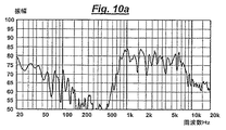
図10A及び図10Bは、既存のマイクロスピーカを備えた既知のDELL(商標)ラップトップコンピュータと、タッチパッドを図9A乃至図9Cのタッチパッド組立体と置き換えたラップトップコンピュータの周波数応答を示す。測定値は、測定出力に対して影響しないほど十分に重い平坦なデスク上に載置されたラップトップコンピュータを使用して、リストパッドの25cm上方で取られた。本発明によるラップトップコンピュータは、高音域レベルが改善される利点を有する。
【0064】
更に、本発明によるラップトップコンピュータは実質的に容量性のインピーダンスのスピーカを有する。特に、インピーダンス係数は1kHzにおける1000オームを超える値から10kHzにおいて100オームまで下降する。従って特に音楽の場合、スピーカの出力量は周波数が高くなると一般に下降する。
【0065】
図10Cは、タッチパッドが図9Aに示されるものと同じ組立体と置き換えられたコンパック(商標)のラップトップコンピュータの特性を示す。変換器はタッチパッド上に取り付けられ、タッチパッドと該タッチパッドの両側のケーシング(リストレスト)の両方を駆動する。パネルの境界条件は図9Dのように定められる。タッチパッドの両側のリストレストは、等しい機械的インピーダンスを有するように適合される。変換器のインピーダンスは組み合わせられたパネルとリストレストの全体のインピーダンスと整合するように設計された。従って、変換器は通常のビームよりも幅が広い、長さがそれぞれ42mmと39mmの二重ビーム変換器である。
【0066】
図示されるように図10Cはおよそ400Hzの低周波数限界を有する。音響出力はパネル背面の音響負荷によって支配され、パネル後部の小空間が減少すると帯域幅は大幅に短縮されることになる。例えば、200Hzまで下方に拡張される帯域幅は6mmの空間内で適切な変換器を使用して実現することができるが、空間が2mmまで減少すると低周波数限界は600Hzまで上昇する。
【0067】
図11Aは、タッチスクリーン(214)と、制御及びデータ入力のためのボタン(216)とを有する場合が多い個人用携帯型端末(PDA)の正面図を示す。図9の断面図はPDAを更に詳細に示す。ケース(218)は通常2つの部品で作られ、互いに嵌合してディスプレイスクリーン(220)を収容し、電子部品は内部プリント基板(224)上に取り付けられる。ケースの後部(通常プラスチック成型品)は、スタブ(66)を介して変換器(108)を取り付けることによって音響を放射するために使用される。変換器(108)は、第2のスタブ(152)により接続された第2のビーム(110)と共にスタブ(66)を駆動する長いビーム(112)を備える。この場合、長いビームはケース(218)に近接しているが、どのような弊害もなしにこの2つのビームを交換することができる。電気的入力の接続のためにリード線が設けられる。
【0068】
図12Aは、例えば陰極線管として、又は液晶ディスプレイとして、任意の望ましい形態に形成された視覚的表示ユニット(137)の斜視図を示す。ユニット(137)は、前面にディスプレイスクリーン(37)が取り付けられたボックス状のハウジング(101)と、後部面及び対向する側面(102)とを有する。図12Bに更に明確に示されるように、ほぼ矩形のパネル(2)が、対向する側面(102)の各々の溝(3)によって定められる。各パネル(2)は2枚のスキン(21)の間に挟まれたコア(22)を備える。上述のように、二重ビーム変換器(108)が各パネル(2)に取り付けられ、パネル中に撓み波を放射/励振し、パネルを共振させて音響出力を生成する。
【0069】
意図的なモード変換器(108)を使用すると、変換器の機械的インピーダンスを側面と整合させることによって良好な機械的結合を得ることができる。従って、音響性能が最適化されるように、すなわち軽量で高剛性にパネル(2)を特に設計することができても、これは不可欠なことではない。これによりモニタ/TV製造者によって使用される、製造上の要件及び方法を実質的に変更する必要性が回避される。
【0070】
図13A乃至図13Cは、クレジットカード(226)の本体(228)のポケット(230)内に単一ビームの変換器(62)が装着されたクレジットカード(226)を示す。変換器(62)はカードを駆動し、本体(228)と一体成型することができるスタブ(66)により音響を放射する。ポケット(230)により、変換器(62)の端部はカードの他の部分にいっさい接触せず自由に振動することが可能になる。カードは、電源、メモリ、信号処理装置、及び増幅器を備えることができ、変換器(62)とリンクされたワイヤ(236)に接続された埋込型電子回路(230)により給電される。適切な紙、プラスチック、又は金属で作ることができる薄いカバー(232)が設けられ、変換器(62)及び電子回路(230)を密閉する。
【0071】
図14は、表ページ(83)と裏ページ(85)を有する折り畳み部材の形態のグリーティング又は同様のカード(81)を示す。変換器(62)はページの内の1枚、好ましくは裏ページ(146)に小さなスタブ(図示せず)によって取り付けられ、該ページを振動させ、これを共振させて音響出力を生成する。変換器(62)は信号発生器/増幅器バッテリユニット(87)によって駆動され、該ユニットはカードの折り目に隠されたスイッチ(89)によって始動され、その結果、カードを開いたときに合い信号発生器を始動させるようにする。
【0072】
図15A及び図15Bは、図11A及び図11Bと同様のPDAを示し、従って共通の要素は同じ参照番号を有する。このPDAは、タッチスクリーン(214)を保護するリッド(215)を備え、該リッドが開いた位置、すなわち通常の使用位置で示されているという点で相違する。二重ビーム変換器(108)はスタブ(66)によってリッド(215)に取り付けられ、リッド(215)をラウドスピーカとして使用することを可能にする。このスタブ(66)はリッド(215)と一体成型することができる。変換器(108)は、スタブ(152)によって共に接続された、長さが異なる2つのビーム(110、112)を備える。PDA(図示せず)の本体(218)内の駆動回路に対してワイヤによって電気接続を形成する。
【0073】
残りの図は、図1乃至図15bに具現化された埋込型ラウドスピーカと共に使用することができる別の変換器を示す。意図的なモード変換器は、可動コイル/永久磁石設計と比較して質量及び奥行きを小さく設計することができる。従って、このような変換器を使用すると、ラウドスピーカの全重量を低減すべきであり、該変換器はスペースが限られている設置に好適であるはずである。従って、該変換器は図1乃至図15Bに示される携帯用装置には理想的である。
【0074】
図16は、スタブ(48)形態の接続手段によって第2の圧電ビーム(51)が後部に取り付けられた第1の圧電ビーム(43)を備え、該スタブが両方のビームの中心に配置された変換器(42)を示す。各ビームはバイモルフである。第1のビーム(43)は圧電材料の2つの層(44、46)を備え、第2のビーム(51)は2つの層(50、52)を備える。圧電材料の各層の極性方向は、矢印(49)で示される。各層(44、50)はバイモルフ内の別の層(46、52)に対して反対の極性方向を有する。バイモルフはまた、平行電気接続を可能にすると同時に、セラミック圧電層に強化要素を付加する中心導電ベーンを備えることができる。各ビーム(44、46)の各々の層は同じ/異なる圧電材料で作ることができる。各層は一般に長さが異なる。
【0075】
第1の圧電ビーム(43)は、第1のビームの中心に配置されたスタブ(56)の形態の結合手段によってパネル(54)上に取り付けられる。第1のビームをその中心に取り付けることにより、偶数次のモードだけが出力を生成することになる。第2のビームを第1のビームの背後に配置し、両方のビームをスタブを用いて中心に結合することによって、両ビームは同軸に位置合わせされた、又は同一の位置を駆動していると考えることができる。
【0076】
各要素が一体結合されると、各々の要素が他の要素のモードを変更するので、結果として得られるモード分布は周波数の別個のセットの合計にはならない。2つのビームは、これらの個々のモード分布がインターリーブされて、変換器の全体のモダリティを向上させるように設計されている。2つのモードは一体化され、対象の周波数領域にわたって有効な出力を生成する。偶数位モードにおける圧電ビーム間の個々の干渉により、局所的に狭いディップが発生する。
【0077】
第2のビームは、2つのビームの基本共振周波数比を使用して選択することができる。材料及び厚みが同一の場合は、周波数比は長さの比の2乗となる。高いf0(基本周波数)が単純に他の大きなビームのf0とf1の間の中間に配置されると、より小さなビームのf3と、より低いビームのf4とは一致する。
【0078】
2つのビームの周波数比に対するコスト関数のグラフをプロットすると、理想的な比率は1.27:1であることが示され、すなわちこの点でコスト関数が最小になる。この比はWO97/09482に記載された(f02:f20の比)「黄金」アスペクト比に相当する。変換器のモダリティの改善方法は、変換器の3つの圧電ビームを使用することによって拡張することができる。理想的な比は1.315:1.147:1である。
【0079】
能動素子例えばビームを一体化する方法は、圧電ディスクの使用することに拡張することができる。2つのディスクを使用すると、2つのディスクのサイズ比は考慮に入れるモード数に依存する。高次モード密度では、約1.1+/−0.02から1までの基本周波数比が良好な結果をもたらすことができる。低次モード密度(すなわち最初の数モード又は最初の5モード)では、約3.2:1の基本周波数比が良好である。最初のギャップは、大きなディスクの第2のモードと第3のモードとの間に生じる。
【0080】
各ディスクの第1の半径方向モードと第2の半径方向モードとの間に大きなギャップがあるので、2つのディスクよりは3つのディスクで非常に良好なインターリーブが得られる。二重ディスク変換器に第3のディスクを追加する場合に、第1の明白な目標は、先の場合の大きなディスクの第2のモードと第3のモードとの間のギャップを埋めることである。しかしながら、等比数列は、これが唯一の解決法でないことを示している。基本周波数f0、α.f0、α2.f0を使用して、rms(α,α2)をプロットすると、αに関して2つの重要な最適値が存在する。その値は、約1.72及び2.90であり、後者の値は明白なギャップ充填法に対応している。
【0081】
基本周波数f0、α.f0、及びβ.f0を両スケーリングが自由なように使用し、上記αの値をシード値として使用すると、僅かに良好な最適値が得られる。パラメータ対(α,β)は、(1.63,3.03)及び(3.20,8.19)である。これら最適値は非常に浅く、すなわちパラメータ値の10%、又は20%の変動でさえ許容可能である。
【0082】
組み合わせられるべき種々のディスクを決定する別の方法は、3つのディスクの半径比の関数としてコストを考慮することである。コスト関数は、RSCD(中心差分の和の比)、SRCD(中心差分の比の和)、及びSCR(中心比の和)とすることができる。モード周波数f0、f1、fn、...fNのセットに関して、これらの関数は以下のように定義される。
RSCD(中心差分の和の比)は

【0083】
或いは又は追加として、受動素子を変換器に組み込み、全体のモダリティを改善することができる。能動及び受動素子はカスケード配置とすることができる。図17は、能動及び受動要素のモードがインターリーブされるように、例えば薄い金属プレートの2つの受動共振素子(74)と共に積み重ねられた2つの能動圧電素子(72)を備える多層ディスク変換器(70)を示す。
【0084】
該素子は、各能動及び受動素子の中心に配置されたスタブ(78)形態の接続手段によって接続される。要素は同心状に配置される。各素子は異なる寸法を有し、最小ディスクと最大ディスクは積層の頂部と底部にそれぞれ配置されている。変換器(70)は、最大ディスクである第1の受動装置の中心に配置されたスタブ(78)の形態の結合手段によって、パネルなどの負荷装置(76)上に取り付けられている。
【0085】
変換器のモダリティを改善する方法は、圧電プレートの形態の2つの能動素子を有する変換器まで拡張することができる。寸法が(1×α)及び(α×α2)の2枚のプレートは、(3/7,4/9)に位置で結合される。従って、周波数比は約1.3:1(1.14×1.14=1.2996)である。
【0086】
図18に示されるように、結合手段(105)を有する圧電変換器(106)の端部に小質量体(104)を取り付けることができる。図19において変換器(114)は、例えばW097/09842に記載されたような、能動素子(115)形成するボイスコイルと、モードプレート(118)の形態の受動共振素子とを有する、慣性電気力学式可動コイル励振器である。能動素子(115)はモードプレート(118)上の該モードプレートの中心から外れて取り付けられる。
【0087】
モードプレート(118)はカプラ(120)によってパネル(116)上に取り付けられる。カプラは能動素子の軸(119)と位置合わせされているが、パネル(116)の平面に垂直な軸(Z)には一致しない。従って、変換器はパネル軸(Z)と一致しない。能動素子は電線(122)を介して電気信号入力に接続される。モードプレート(118)は、そこからの音響放射を減少させるように穿孔され、能動素子はモードプレート(118)の中心から外れて、例えば最適な取付位置、すなわち(3/7,4/9)に配置される。
【0088】
図20はスタブの形態の結合手段(126)によってパネル(128)に取り付けられる能動圧電共振素子を備える変換器(124)を示す。変換器(124)とパネル(128)の幅対長さの比は両方とも1:1.13である。結合手段(126)は変換器又はパネルのいずれの軸(130,Z)とも位置合わせされていない。更に、結合手段の配置は最適の位置、すなわち変換器(124)とパネル(128)の両方に対して中心を外れた位置に配置される。
【0089】
図21はビームの形態の能動圧電共振素子形態の変換器(132)を示す。変換器(132)はスタブの形態の2つの結合手段(136)によってパネル(134)に結合される。1つのスタブはビームの端部(138)方向に配置され、他のスタブはビームの中心方向に配置される。
【0090】
図22は、結合手段(144)によって結合された2つの能動共振素子(142、143)と、該結合手段(144)及び共振素子(142)を取り囲むエンクロージャ(148)とを備える変換器(140)を示す。従って変換器は耐衝撃性及び衝突性がある。エンクロージャは、変換器の動作を妨げないように機械的インピーダンスの低いゴム又は類似のポリマーで作られる。ポリマーが耐水性であれば変換器(140)は防水性にすることができる。
【0091】
上部共振素子(142)はスタブの形態の結合手段を介してパネル(145)に結合される下部共振素子(143)よりも大きい。スタブは下部共振素子(143)の中心に配置される。各々の能動素子用の出力カップリング(150)はエンクロージャから延びて、負荷装置(図示せず)への良好な音響取付が可能となる。
【0092】
図23はプレート形状能動共振素子の形態の変換器(160)を示す。共振素子には、フィンガー(164)を形成して複合共振システムを形成するスロット(162)が形成されている。共振素子は、スタブ(166)の形態の結合手段によってパネル(168)に取り付けられる。
【0093】
図24A及び図24Bにおいて、変換器(14)は平面の外側に湾曲した矩形で、米国特許第5632841号(国際特許出願WO96/31333)に開示された形式の、NASDRIVの商標でPAR Technologies Incが製造している、圧縮応力が加えられた圧電変換器である。従って、変換器(14)は能動共振素子である。該変換器は、幅(W)、長さ(L)、取付点(16)位置(X)を有する。
【0094】
変換器(14)が湾曲していることは、結合手段(16)の取付ラインの形態になることを意味する。変換器が中心を通る短軸に沿った取付ラインに沿って取り付けられると、変換器の2つのアームの共振周波数は一致する。最適なサスペンションポイントはモデル化することができ、共振素子の長さ方向に沿って43%乃至44%の取付ラインである。コスト関数(すなわち「悪さ」の尺度)はこの値で最小化され、これは長さの4/9における取付点の推定値に相当する。更にコンピュータによるモデル化により、この取付点が変換器の幅の領域に関して有効であることが示された。共振素子の長さに沿った33%乃至34%における第2のサスペンション点もまた適切であると思われる。
【0095】
長さに沿って44%に取り付けられた共振素子におけるコスト(すなわち、自乗平均中心比)対アスペクト比(AR=W/2L)のグラフをプロットすることによって、コスト関数がこの値で最小になることから、最適なアスペクト比は1.06+/−0.01乃至1であるように決定することができる。
【0096】
パネル(12)に対する最適取付角度θは、最適な角度を見つけるために2つの「悪さの尺度」を使用して求めることができる。例えば、応答のログ(dB)大きさの標準偏差は「粗さ」の尺度である。利点/悪さのこのような数字は本出願人らの国際特許出願WO99/41839で説明されている。最適化された変換器、すなわちアスペクト比が1.06:1でモデル化を使用した取付点が44%の変換器に関しては、取付位置が対称ではないので、取付(16)ラインを回転させると著しい効果が得られる。換言すれば左側に面しているより長い端部で約270°という角度の選択肢がある。
【0097】
図25A及び図25Bは、台形断面を有する共振素子形態の非対称形状変換器(18)を示す。台形の形状は2つのパラメータ、すなわちAR(アスペクト比)及びTR(テーパ比)によって制御される。AR及びTRは、例えばラインのいずれかの側の等価質量などの、ある制約が満足されるように第3のパラメータλを決定する。
【0098】
等価質量(又は等価面積)の制約方程式は次の通りである。
等価慣性モーメント(又は面積の等価2次モーメント)に関する制約方程式は次の通りである。
![]()
コスト関数(すなわち「悪さ」尺度)は、ARの0.9から1.25までの範囲、TRの0.1から0.5の範囲、等価質量において制約されるλでFEAを40回実行した結果についてプロットした。すなわち変換器は質量中心に取り付けられる。結果は下表に示され、AR=1、TR=0.3をもつ、λが43%に近づく最適な形状があることが示される。
従って、台形変換器の1つの利点は、変換器が重心/質量中心にあるが対称線ではない取付ラインに沿って取り付けることができることである。従ってそのような変換器には、慣性的に不均衡とならずにモード分布が改善される利点があることになる。先に使用された2つの比較法は、配向の最適な角度として再度270°乃至300°を選択する。
【0101】
本発明に使用される変換器は、例えばWO97/09842に記載されたように変換器が分布モードのオブジェクトとして設計される、分布モードパネルとは相反するものとして理解することができる。
【図面の簡単な説明】
【0102】
【図1A】本発明を具現化する使い捨てラウドスピーカの正面斜視図である。
【図1B】図1AのAA線に沿った断面図である。
【図2A】本発明を具現化するラウドスピーカ構成要素の正面斜視図である。
【図2B】本発明を具現化するラウドスピーカ構成要素の側面図である。
【図3】本発明を具現化するパーソナルコンピュータ用のマウス又はポインティングデバイスの断面図である。
【図4】エンクロージャに取り付けられた本発明を具現化するラウドスピーカの断面図である。
【図5】本発明を具現化する個人用携帯型情報端末又は他の携帯用コンピュータの断面図である。
【図6A】本発明を具現化するラウドスピーカシステムの側面図である。
【図6B】本発明を具現化するラウドスピーカシステムの平面図である。
【図7】本発明を具現化するラップトップコンピュータの斜視図である。
【図8】本発明を具現化する第2のラップトップコンピュータのAA線に沿った(図7に示される)断面図である。
【図9A】タッチパッド組立体の平面図である。
【図9B】タッチパッド組立体の断面図である。
【図9C】電子装置に組み込まれた図9A及び図9Bのタッチパッド組立体の部分断面図である。
【図9D】図9A及び図9Bのタッチパッド組立体を組み込んだラップトップのケーシング内部の部分斜視図である。
【図10A】既知のラップトップにおける音響出力対周波数のグラフ。
【図10B】図9Aのタッチパッド組立体を使用するラップトップにおける音響出力対周波数のグラフ。
【図10C】図9Bのタッチパッド組立体を使用する第2のラップトップにおける周波数に対してdBで表した空間的平均伝達関数のグラフ。
【図11A】本発明を具現化する個人用携帯型情報端末(PDA)の正面図である。
【図11B】図11AのPDAの側断面図である。
【図12A】本発明を具現化する視覚的表示装置(VDU)の斜視図である。
【図12B】図12AのVDUの一部の断面図である。
【図13A】本発明を具現化するクレジットカードの正面図である。
【図13B】図13Aの線A−Aに沿ったクレジットカードの側断面図である。
【図13C】図13Aの線B−Bに沿ったクレジットカードの側断面図である。
【図14】本発明を具現化するグリーティングカードの斜視図である。
【図15A】本発明を具現化する個人用携帯型情報端末(PDA)の正面図である。
【図15B】図15AのPDAの側断面図である。
【図16】本発明に使用することができる別のモード変換器の側面図である。
【図17】本発明に使用することができる別のモード変換器の側面図である。
【図18】本発明に使用することができる別のモード変換器の側面図である。
【図19】本発明に使用することができる別のモード変換器の側面図である。
【図20】本発明に使用することができる別のモード変換器の側面図である。
【図21】本発明に使用することができる別のモード変換器の側面図である。
【図22】本発明に使用することができる別のモード変換器の側面図である。
【図23】本発明に使用することができる別のモード変換器の平面図である。
【図24a】本発明に使用することができる変換器のパラメータモデルの概略平面図である。
【図24b】図24aの変換器の取付ラインに垂直な断面である。
【図25a】本発明に使用することができる変換器のパラメータモデルの概略平面図である。
【図25b】図25aの変換器の概略平面図である。
【符号の説明】
【0103】
62 変換器
66 接続スタブ
190 デスクトップコンピュータ
192 ディスプレイスクリーン
194 リッド
196 ヒンジ
198 ベース
200 キー
201 端部の中心
202 タッチパッド
204 撓み波音響ラジエータ【Technical field】
[0001]
The present invention relates to electronic articles, and more particularly to low-power or self-contained articles such as, for example, electronic articles for personal use such as mobile phones, personal organizers, and pocket radios.
[Background]
[0002]
It is known from international patent application WO 00/69212 to provide a personal portable electronic article having a body or casing with a flexural loudspeaker mounted therein or thereon. The flexural wave loudspeaker includes an acoustic radiator and a vibration exciter that is attached to the radiator and vibrates the radiator to generate an acoustic output. The radiator is integrally formed with the main body or casing by injection molding and defines a sub-region of the main body or casing. A personal portable electronic article means an article that is small enough to be held.
[0003]
The radiator can be a distributed mode acoustic radiator speaker of the kind described in international patent application WO 97/09842.
[0004]
Generally, personal portable electronic articles are either low-power devices or self-powered devices.
[0005]
[Patent Document 1]
International Patent Application WO00 / 69212
[Patent Document 2]
International Patent Application WO97 / 09842
DISCLOSURE OF THE INVENTION
[Means for Solving the Problems]
[0006]
According to the present invention, an electronic article includes a main body or a casing in which a bending wave loudspeaker is mounted or mounted, and the loudspeaker is attached to the bending wave acoustic radiator and the radiator to vibrate the radiator. An electromechanical force transducer for generating an acoustic output, the transducer having an intended operating frequency region and having a frequency distribution of modes in the operating frequency region and the transducer as a radiator A coupling means for mounting is provided. The coupling means may be attached to the resonant element.
[0007]
The electronic article may be a remotely powered article with either a light or infrared power source, for example. Thus, the electronic article can be selected from a wireless panel, a personal PA, or a solar panel. Electronic goods include portable radio, walkman, personal digital assistant (PDA), electronic toy, buzzer, polyphonic or monophonic sounder, chime, electronic novelty, laptop, computer mouse, keyboard, display case, personal computer, monitor Or a low-power article such as a cordless product, such as a television. The electronic article may also be disposable such as a disposable speaker or buzzer, a low cost communication device, a credit card, a novelty, a book or a card.
[0008]
The acoustic radiator can be molded or integrally molded with the body or casing. The radiator can be transparent, for example to define the area of the display screen.
[0009]
The acoustic radiator may be a touch pad. The acoustic radiator can be the whole or part of the casing surrounding the touchpad. The coupling means may comprise a touch pad acoustically coupled to the casing, for example by a frame surrounding the outer periphery of the touch pad. The transducer can be mounted either directly on the touchpad relative to the touchpad or on the frame, and the transducer drives the casing. The touchpad can be coupled to the casing using an integral securing clip or a separate securing component such as a bolt, screw, or bayonet fixture. Alternatively, the touchpad can be frictionally locked to the casing.
[0010]
In this manner, the acoustic radiator can be driven using an integrated assembly comprising a touchpad and a transducer. Both the touchpad and the casing surrounding the touchpad function as an acoustic radiator, and the casing functions as a first acoustic radiator. If necessary, at least one transducer can be added and attached to the first acoustic radiator. The touchpad assembly can be replaced with a standard touchpad of any electronic device such as a laptop or a personal digital assistant.
[0011]
The resonant element can be, for example, a piezoelectric transducer, and can be active, which can be in the form of a strip of piezoelectric material. Alternatively, the resonant element may be passive and the transducer further comprises an active transducer that is an inertial or grounded vibratory transducer, actuator or exciter, such as a moving coil transducer, for example. it can. The active transducer may be a bending or twisting transducer (eg of the type taught in WO 00/13464). Furthermore, the transducer can comprise a combination of passive and active elements forming a hybrid transducer.
[0012]
Many transducers, exciters, or actuator mechanisms have been developed to apply forces to structures such as, for example, loudspeaker acoustic radiators. There are various types of these transducer mechanisms, such as moving coils, moving magnets, piezoelectric or magnetostrictive types. Typically, electrodynamic loudspeakers using coil and magnet transducers can lose 99% of the input energy as heat, while piezoelectric transducers can only lose 1%. Therefore, piezoelectric transducers are popular because of their high efficiency.
[0013]
There are several problems with piezoelectric transducers, for example, they are so stiff that they are essentially comparable to brass stays and are therefore difficult to adapt to acoustic radiators, especially air. When the rigidity of the transducer increases, the frequency of the fundamental resonance mode moves to the high frequency side. That is, the piezoelectric transducer can be considered to have two operating regions. The first operating region is a region lower than the fundamental resonance frequency of the transducer. This is the “stiffness control” region, where the speed increases with frequency and usually the output response needs to be equal. This leads to a loss of available efficiency. The second region is a resonance region exceeding the rigid region and is generally avoided because the resonance is very intense.
[0014]
Furthermore, since the general teaching is to suppress resonance in the transducer, piezoelectric transducers are generally used only in the range below the fundamental resonant frequency of the transducer. When the piezoelectric transducer is used in a range exceeding the fundamental resonance frequency, it is necessary to apply vibration suppression to suppress the resonance peak.
[0015]
The problem with piezoelectric transducers applies equally well to transducers of other “smart” materials: magnetostrictive, electrostrictive, and electret type materials. For example, European Patent Publication EP 0993231A of Shinsei Corporation, European Patent Publication EP 0888566A of Shinsei Corporation, Murata Manufacturing Co., Ltd. Limited, U.S. Pat. No. 4,593,160, Sanyo Electric Co. Various piezoelectric transducers are known, such as described in Limited US Pat. No. 4,401,857, Altec Corporation US Pat. No. 4,481,663, and Sawafuji UK patent application GB 2,166,022A. It is. However, the object of the present invention is to use an improved transducer.
[0016]
The converter used in the present invention can be considered an intentional mode converter. The coupling means can be attached to the resonant element at a position that is advantageous for coupling the mode operation of the resonant element to the interface. Parameters of the resonant element, such as aspect ratio, flexural rigidity, thickness and dimensions, can be selected to improve the mode distribution in the resonant element in the operating frequency range. The flexural rigidity and thickness of the resonant element can be selected to be isotropic or anisotropic. The flexural rigidity and / or thickness can be selected to improve the mode distribution of the resonant element. For example, parameters can be selected using analysis such as computer simulation using FEA or modeling.
[0017]
The distribution can be improved by ensuring that the first mode of the active device is close to the lowest operating frequency of interest. The distribution can also be improved by ensuring that the mode of the operating frequency range is satisfactory, i.e. high density. The mode density is preferably sufficient to give the active device a substantially constant effective average force with respect to frequency. Effective smoothing of mode resonance can be obtained by good energy transfer. Alternatively or additionally, improving the mode distribution by distributing it substantially uniformly with respect to the resonant flexural wave mode frequency, i.e. by smoothing the peak of the frequency response due to mode "crowding" or grouping. it can. Such converters are known as distributed mode converters or DMTs.
[0018]
Such intended modes, i.e. distributed mode converters, are described in international patent application WO001 / 54450.
[0019]
The converter can comprise a plurality of resonant elements each having a mode distribution, and the modes of the resonant elements are arranged to interleave in the operating frequency region and improve the mode distribution of the converter as a whole device. Yes. The resonant elements can have different fundamental frequencies, and thus parameters such as the load, dimensions, or flexural wave stiffness of the resonant elements can be different.
[0020]
The resonant elements can be coupled together in any convenient manner by connecting means, for example on a generally rigid stub between the resonant elements. The resonant elements are preferably coupled at a coupling point that improves the transducer modality and / or improves coupling where force is to be applied. The parameters of the connecting means can be selected to improve the mode distribution of the resonant element. The resonant elements can be stacked. The coupling point can be aligned in the axial direction.
[0021]
The resonant element may be plate-shaped or curved outside the plane. The plate-shaped resonant element is formed with slots or cuts, and can form a composite resonant system. The resonant element may be beam-shaped, trapezoidal, super-elliptical, or generally disk-shaped. Alternatively, the resonance element may be rectangular, and may be curved outside the rectangular plane around an axis along a symmetrical minor axis.
[0022]
The resonant element may be modal along two substantially perpendicular axes, each having an associated fundamental frequency. The two fundamental frequency ratios can be adjusted to, for example, 9: 7 (1.286: 1) so that the mode distribution is optimal.
[0023]
As an example, the configuration of such a mode converter can be any of the following: A flat piezoelectric disk, a combination of at least two or preferably at least three flat piezoelectric disks, two identical piezoelectric beams, a combination of multiple identical piezoelectric beams, a curved piezoelectric plate, a plurality of curved piezoelectric plates or 2 A combination of two identical piezoelectric beams.
[0024]
The interleaving of the mode distribution of each resonance element can be improved by optimizing the frequency ratio of the resonance elements, that is, the frequency ratio of each fundamental resonance frequency of each resonance element. Accordingly, the parameters of each resonant element that are related to each other can be changed to improve the overall mode distribution of the transducer.
[0025]
When two active resonant elements having a beam shape are used, the frequency ratio (ie fundamental frequency ratio) of the two beams can be 1.27: 1. In a transducer with three beams, the frequency ratio can be 1.315: 1.147: 1. In a transducer with two disks, the frequency ratio that optimizes the higher order mode density can be 1.1 +/− 0.02: 1 and the frequency ratio that optimizes the lower order mode density is 3. 2: 1. In a transducer with three disks, the frequency ratio can be 3.03: 1.63: 1 or 8.19: 3.20: 1.
[0026]
The parameters of the coupling means can be selected to improve the mode distribution of the resonant elements in the operating frequency range. The coupling means can be a trace, such as a controlled adhesive layer.
[0027]
The coupling means can be arranged asymmetrically with respect to the panel so that the transducers are coupled asymmetrically. For example, asymmetry can be achieved in several ways, such as adjusting the position or orientation of the transducer relative to the symmetry axis of the panel or transducer.
[0028]
The coupling means can form a mounting line. Alternatively, the coupling means can form an attachment point or a small local area if the area of attachment is small relative to the dimensions of the resonant element. The coupling means may be in the form of a stub, for example having a small diameter of 3 to 4 mm. The coupling means can be of low mass.
[0029]
The coupling means can comprise two or more coupling points and can comprise a combination of attachment points and / or attachment lines. For example, two attachment points or small local attachment areas can be used, one near the center of the active element and one at the end of the active element. This is useful for plate-shaped transducers that are generally rigid and have a high natural resonance frequency.
[0030]
Alternatively, only a single point of attachment can be provided. This can provide an advantage in the case of a composite resonant element array, where the outputs of all resonant elements are summed by a single coupling means, so that it is not necessary to sum the outputs by the load. The coupling means can be selected to be placed at the antinode on the resonant element and can be selected to provide a constant average force with respect to frequency. The coupling means can be arranged away from the center of the resonant element.
[0031]
The position and / or orientation of the attachment line can be selected to optimize the mode density of the resonant element. The attachment line preferably does not coincide with the symmetry line of the resonant element. For example, in a rectangular resonant element, the attachment line can be offset from the symmetrical minor axis (ie, the center line) of the resonant element. The attachment line can be oriented not parallel to the symmetry axis of the panel.
[0032]
The shape of the resonant element is approximately at the center of mass of the resonant element and can be selected to provide an off-center attachment line. One advantage of this embodiment is that there is no inertial imbalance because the transducer is mounted at its center of mass. This can be achieved by an asymmetrical resonant element that is an unequal quadrilateral or trapezoid.
[0033]
In a beam-shaped or substantially rectangular resonant element, the attachment line can extend across the width of the resonant element. The area of the resonant element may be smaller than the area of the acoustic radiator.
[0034]
The acoustic radiator may be in the form of a panel. The panel may be flat and lightweight. The material of the acoustic radiator may be anisotropic or isotropic.
[0035]
The acoustic radiator can have a resonant bending wave mode distribution as taught in WO 97/09842, and the characteristics of the acoustic radiator can be selected such that the resonant bending wave mode is distributed substantially uniformly with respect to frequency. Can be selected, i.e., to smooth the peaks of the frequency response due to a "crowd" or grouping of modes.
[0036]
In particular, the characteristics of the acoustic radiator can be selected such that the low frequency resonant flexural wave modes are distributed substantially uniformly over frequency. The low frequency resonant bending wave mode is preferably the 10 to 20 lowest frequency resonant bending wave mode of the acoustic radiator.
[0037]
The transducer position may be selected to couple substantially uniformly to a resonant bending wave mode in the acoustic radiator, particularly a low frequency resonant bending wave mode. In other words, the transducer can be mounted at a position where the acoustic radiator has a relatively large number of vibrationally active resonant antinodes and vice versa. Any such location can be used, but the most convenient location is between 38% and 62% near the center along each of the length and width of the acoustic radiator, but off-center locations. It is. A specific or preferred position is a distance of 3/7, 4/9, or 5/13 along the axis, with different ratios being preferred for the longitudinal and width axes. A suitable ratio of an isotropic panel having an aspect ratio of 1: 1.13 or 1: 1.41 is 4/9 in length and 3/7 in width.
[0038]
The operating frequency region can be an audible region and / or an ultrasonic region over a relatively wide frequency range. Also, the operational effectiveness of the distributed mode converter can be applied in sonar and sound source ranging and imaging where a wide bandwidth and / or possible high power would be useful. Thus, operation over a region beyond the range defined by the single dominant natural resonance of the transducer can be achieved.
[0039]
The minimum frequency in the operating frequency region is preferably greater than a predetermined lower limit, which is approximately the fundamental frequency of the transducer.
[0040]
For example, for a beam-like active resonant element, the force can be extracted from the beam center and can be adapted to the mode shape of the acoustic radiator to which the active resonator is attached. In this way, action and reaction cooperate to give a constant output with respect to frequency. By connecting the resonant element to the acoustic radiator at the antinode of the resonant element, the primary resonance of the resonant element is considered to have a low impedance. In this way, the acoustic radiator should not amplify the resonance of the resonant element.
[0041]
According to a second embodiment of the present invention, there is provided a touchpad assembly for use in an electronic article such as a laptop or PDA, the touchpad assembly comprising a touchpad and the touchpad as an electronic device. A coupling means for mechanically coupling to the casing of the article; and a transducer attached to the coupling means or touchpad to drive the casing as an acoustic radiator.
[0042]
The coupling means may be in the form of a frame that surrounds the outer periphery of the touchpad. The transducer can be mounted on a touchpad or frame. The touchpad can be coupled to the casing using an integral securing clip or a separate securing component such as a bolt, screw, or bayonet fixture. Alternatively, the touchpad can be frictionally locked to the casing.
The invention is shown schematically in the accompanying drawings by way of illustration.
BEST MODE FOR CARRYING OUT THE INVENTION
[0043]
FIGS. 1A and 1B show disposable loudspeakers, such as polyphonic sounders, disposable buzzers, credit cards, and other novel loudspeakers. The loudspeaker is a panel (60) capable of supporting bending wave vibration, preferably resonant bending wave vibration, and a conversion attached to the panel (60) by a connection stub (66) to excite the bending wave vibration and generate an acoustic output. (62). The converter (62) is an intentional mode converter or distributed mode converter, as described above and described in WO 01/54450. The transducer (62) comprises a piezoelectric plate element (64). Electrical input is supplied to the element (64) by two flexible wires in the form of connecting leads (68).
[0044]
FIG. 2 shows a loudspeaker (58) similar to FIGS. 1A and 1B, where like elements have been given the same reference numerals. The loudspeaker (58) is mounted on a support frame (84) that extends around the outer periphery of the loudspeaker by means of a flexible peripheral edge (86). The support frame (84) allows the loudspeaker to be easily attached to a surface support or another support.
[0045]
FIG. 3 shows a cross section of a mouse (88) used as a pointing device for a computer system (not shown). The mouse (88) includes standard parts such as a ball (90), a lower case (92), and a cover (94). The cover (94) is designed to be able to support bending wave vibrations, preferably resonant bending wave vibrations. The intentional mode converter (108) is attached to the cover (94) by a connection stub (66) and excites flexural wave vibrations to produce an acoustic output.
[0046]
The transducer comprises upper and lower bimorph beams (112) and (110), the upper beam (112) being connected to the cover (94) by a stub (66) extending across the beam width. The width and height of the stub can be 1-2 mm and can be made of high quality plastic and / or metal with a suitable insulating layer to prevent electrical shorts.
[0047]
The upper beam (112) is longer than the lower beam (110), and these beams are connected by a centrally mounted stub (152). Each beam consists of three layers, the outer two layers being a piezoceramic material, eg PZT 5H, with a central brass vane in between. The outer layer can be attached to the brass vane with an adhesive layer, typically 10-15 microns thick.
[0048]
FIG. 4 shows a panel (60) capable of supporting bending wave vibrations, preferably resonant bending wave vibrations. The panel (60) is mounted in the closure box (154) by a flexible suspension (156) that extends around the outer periphery of the panel (60). The intentional mode converter (108) is attached to the panel (60) by a connection stub (66) similar to that used in FIG. 3, and excites flexural wave vibrations to produce an acoustic output.
[0049]
The closed box (154) generally prevents the sound radiated from the back surface (155) of the panel (60) from interfering with the sound radiated from the front surface (157) of the panel. Thus, the box (154) functions as a baffle to prevent acoustic cancellation. Box (154) can be filled with a suitable absorber.
[0050]
FIG. 5 shows a personal portable with a standard part, a case (176) supporting a key (170), and a lid (180) hinged around the hinge (178) to the case (176). An information terminal (PDA) (158) is shown. The lid (180) supports a display (172), which can be a liquid crystal display (LCD) or a thin film transistor (TFT) display, and a front window (174) that can optionally be mounted on the front of the display (172). . The lid (180) is designed to support bending wave vibrations, preferably resonant bending wave vibrations. A deliberate mode converter (62), such as the converter (62) of FIGS. 1A and 1B, is attached to the lid (180) by a connecting stub (66) to excite flexural wave vibrations and generate an acoustic output. To do.
[0051]
The transducer (62) has a mechanical source impedance that can be matched to the impedance of the lid (180) to obtain maximum output transmission. Alternatively or additionally, the transducer may be attached to the case (176).
[0052]
6A and 6B illustrate a panel (60) capable of supporting bending wave vibration, preferably resonant bending wave vibration, and an intentional mode converter (62) such as the converter (62) of FIGS. 1A and 1B. A loudspeaker system comprising: The transducer (62) is attached to the panel (60) by a connection stub (66) and excites flexural wave vibrations to produce an acoustic output.
[0053]
The signal of the transducer (62) is supplied by an amplifier (182) attached to the panel (60). The system further comprises a power source that supplies power to the amplifier, such as a battery, solar cell, or direct infrared link. Accordingly, the loudspeaker system (186) is adapted to operate as a wireless device that can be used with a wireless panel / personal PA, a self-powered solar panel, a cordless device, or a portable radio / walkman. The system (186) can be a completely remote power supply, such as an optical / infrared power source.
[0054]
7 and 8 show the following standard parts: a base (198) that supports a key (200) and a touchpad (202), and a lid hinged about the hinge (196) relative to the base (198). 194) of a laptop computer (190). A display screen (192) is mounted in the lid (192). The key (200) is placed toward the screen (192). The touchpad (202) used for the pointing function is located near the center of the edge (201) of the base (198) closest to the user.
[0055]
In FIG. 7, two mode converters (62) as used in the embodiment of FIGS. 1A and 1B are attached to the base inner top surface by a stub (66) inside the base. Alternatively, as shown in FIG. 8, a mode converter (108) such as the converter used in FIG. 3 can be used. The top surface of the base is designed to have a region (204) that covers all or part of the surface of the base and can support bending wave vibration, preferably resonant bending wave vibration. In either embodiment, the transducer is attached to two such regions and excites flexural wave vibrations to produce an acoustic output. The transducer can be designed to drive local mechanical impedance to achieve a high level of mechanical coupling efficiency.
[0056]
9A and 9B show a touch pad assembly (203) that can be used in place of the touch pad of FIGS. 7 and 8 or the touch pad of another embodiment of the present invention. The touchpad assembly (203) includes a touchpad (202), a frame (205) extending around the periphery of the touchpad (202), and a transducer (207) attached to the frame. Since the frame is formed with a groove, its cross section has a substantially U-shaped cross section. Both the touchpad (202) and the transducer (207) are mounted in the groove but are separated by a small gap (213).
[0057]
The touchpad (202) is made of a glass fiber reinforced plastic circuit board material and has a mechanical impedance of approximately 3.59 Ns / m. The touch pad (202) is about 0.4 mm thick and a 170 micron plastic laminate is bonded to the front surface of the touch pad (202). A decorative or protective coating is obtained with a plastic laminate.
[0058]
As shown in FIG. 9C, the frame (205) of the touchpad assembly (203) is attached to a casing (209) of an electronic device, such as a laptop computer or a personal digital assistant. The transducer (207) drives flexural wave vibration in the frame (205). Since the frame (205) is mechanically and acoustically coupled to the casing, the vibration of the frame is transmitted to the casing (209). The casing forms the main acoustic radiator of the electronic device.
[0059]
The transducer (207) is selected to match the impedance of the combined touchpad and wristpad. The transducer is preferably a DMT, but alternatively may be, for example, a moving coil transducer, a piezoelectric transducer, a magnetostrictive exciter, or a bending or torsion transducer (eg of the type taught in WO 00/13464). Inertial or grounded vibration transducers, actuators or exciters.
[0060]
FIG. 9D shows the internal section of the laptop computer to which the touchpad assembly is attached. FIG. 9D is a top view of the casing facing downward. The touchpad (202) is supported in a casing (209) having a region (240) where either side of the touchpad (202) forms a wrist rest. The casing (209) also includes an opening (241) into which a keyboard is inserted by a molded partition (242) that separates the opening from the wrist rest area (240). A 1.5 mm thick polystyrene strip (243) is attached below one edge of the wrist rest to help with panel boundary conditions. A second strip (not shown) is attached to the wrist rest on another side of the touchpad. The strip extends between the front wall (244) of the casing (209) and the molding partition (242).
[0061]
In each of the laptop computer embodiments, a small foam spacer is attached to any button on the casing and finned metal foil that connects the chassis of the central processing unit to a heat sink to avoid apparent rattling. can do.
[0062]
The advantage of such a configuration is that the touchpad and the transducer are integrated into a single integrated assembly. Furthermore, an additional electrical connection (211) for the transducer can be easily added to the touchpad (202) that already supports the electrical connection for another purpose. The one-piece assembly not only reduces complexity, weight, and cost, but also offers the possibility of occupying less important space in portable electronic articles.
[0063]
FIGS. 10A and 10B show the frequency response of a known DELL ™ laptop computer with existing micro-speakers and a laptop computer with the touchpad replaced with the touchpad assembly of FIGS. 9A-9C. Measurements were taken 25 cm above the wrist pad using a laptop computer placed on a flat desk that was heavy enough not to affect the measurement output. The laptop computer according to the invention has the advantage that the treble level is improved.
[0064]
Furthermore, the laptop computer according to the invention has a speaker with a substantially capacitive impedance. In particular, the impedance coefficient falls from a value exceeding 1000 ohms at 1 kHz to 100 ohms at 10 kHz. Therefore, especially in the case of music, the output amount of the speaker generally decreases as the frequency increases.
[0065]
FIG. 10C illustrates the characteristics of a Compaq ™ laptop computer in which the touchpad is replaced with the same assembly as shown in FIG. 9A. The transducer is mounted on the touchpad and drives both the touchpad and the casings (wrist rests) on both sides of the touchpad. Panel boundary conditions are defined as shown in FIG. 9D. The wrist rests on both sides of the touchpad are adapted to have equal mechanical impedance. The impedance of the transducer was designed to match the overall impedance of the combined panel and wrist rest. Thus, the transducer is a double beam transducer having a width wider than a normal beam and a length of 42 mm and 39 mm, respectively.
[0066]
As shown, FIG. 10C has a low frequency limit of approximately 400 Hz. The sound output is dominated by the sound load on the back of the panel, and the bandwidth is greatly reduced when the small space behind the panel is reduced. For example, a bandwidth extending down to 200 Hz can be achieved using a suitable transducer in a 6 mm space, but when the space is reduced to 2 mm, the low frequency limit increases to 600 Hz.
[0067]
FIG. 11A shows a front view of a personal portable terminal (PDA) that often has a touch screen (214) and buttons (216) for control and data entry. The cross-sectional view of FIG. 9 shows the PDA in more detail. The case (218) is usually made of two parts and fits together to accommodate the display screen (220), and the electronic parts are mounted on the internal printed circuit board (224). The back of the case (usually a plastic molding) is used to radiate sound by attaching a transducer (108) via a stub (66). The transducer (108) comprises a long beam (112) that drives a stub (66) with a second beam (110) connected by a second stub (152). In this case, the long beam is close to the case (218), but the two beams can be exchanged without any adverse effects. Lead wires are provided for connection of electrical inputs.
[0068]
FIG. 12A shows a perspective view of a visual display unit (137) formed in any desired form, for example as a cathode ray tube or as a liquid crystal display. The unit (137) has a box-shaped housing (101) with a display screen (37) attached to the front surface, a rear surface and opposing side surfaces (102). As more clearly shown in FIG. 12B, a generally rectangular panel (2) is defined by each groove (3) on the opposite side (102). Each panel (2) comprises a core (22) sandwiched between two skins (21). As described above, a dual beam transducer (108) is attached to each panel (2) to radiate / excit flexure waves in the panel and resonate the panel to produce an acoustic output.
[0069]
With the intentional mode converter (108), good mechanical coupling can be obtained by matching the mechanical impedance of the converter with the sides. Therefore, even if the panel (2) can be specifically designed so that the acoustic performance is optimized, i.e. lightweight and rigid, this is not essential. This avoids the need to substantially change the manufacturing requirements and methods used by the monitor / TV manufacturer.
[0070]
FIGS. 13A-13C show a credit card (226) with a single beam transducer (62) mounted in a pocket (230) of the body (228) of the credit card (226). The transducer (62) drives the card and emits sound through a stub (66) that can be integrally molded with the body (228). The pocket (230) allows the end of the transducer (62) to vibrate freely without contacting any other part of the card. The card can include a power source, memory, signal processing unit, and amplifier and is powered by an embedded electronic circuit (230) connected to a wire (236) linked to a transducer (62). A thin cover (232), which can be made of suitable paper, plastic, or metal, is provided to seal the transducer (62) and the electronic circuit (230).
[0071]
FIG. 14 shows a greeting or similar card (81) in the form of a folding member having a front page (83) and a back page (85). The transducer (62) is attached to one of the pages, preferably the back page (146), by a small stub (not shown) that vibrates the page and resonates it to produce an acoustic output. The converter (62) is driven by a signal generator / amplifier battery unit (87), which is triggered by a switch (89) hidden in the card fold so that when the card is opened, a match signal is generated. Try to start the vessel.
[0072]
15A and 15B show a PDA similar to FIGS. 11A and 11B, and thus common elements have the same reference numbers. This PDA differs in that it includes a lid (215) that protects the touch screen (214), which is shown in an open position, ie, a normal use position. The dual beam converter (108) is attached to the lid (215) by a stub (66), allowing the lid (215) to be used as a loudspeaker. The stub (66) can be integrally formed with the lid (215). The transducer (108) comprises two beams (110, 112) of different lengths connected together by a stub (152). Electrical connections are made by wires to drive circuits in the body (218) of a PDA (not shown).
[0073]
The remaining figures show another transducer that can be used with the embedded loudspeaker embodied in FIGS. 1-15b. Intentional mode converters can be designed with reduced mass and depth compared to moving coil / permanent magnet designs. Therefore, the use of such a transducer should reduce the overall weight of the loudspeaker and the transducer should be suitable for installations where space is limited. Thus, the transducer is ideal for the portable device shown in FIGS. 1-15B.
[0074]
FIG. 16 comprises a first piezoelectric beam (43) with a second piezoelectric beam (51) attached to the rear by connecting means in the form of a stub (48), the stub being arranged in the center of both beams. A transducer (42) is shown. Each beam is a bimorph. The first beam (43) comprises two layers (44, 46) of piezoelectric material and the second beam (51) comprises two layers (50, 52). The polarity direction of each layer of piezoelectric material is indicated by arrows (49). Each layer (44, 50) has an opposite polarity direction relative to another layer (46, 52) in the bimorph. The bimorph can also include a central conductive vane that allows parallel electrical connections while simultaneously adding reinforcing elements to the ceramic piezoelectric layer. Each layer of each beam (44, 46) can be made of the same / different piezoelectric material. Each layer is generally different in length.
[0075]
The first piezoelectric beam (43) is mounted on the panel (54) by a coupling means in the form of a stub (56) located in the center of the first beam. By attaching the first beam to its center, only even order modes will produce output. By placing the second beam behind the first beam and coupling both beams to the center using a stub, both beams are coaxially aligned or driving the same position Can think.
[0076]
As each element is coupled together, the resulting mode distribution is not the sum of a distinct set of frequencies, as each element changes the mode of the other element. The two beams are designed such that their individual mode distributions are interleaved to improve the overall modality of the transducer. The two modes are integrated to produce a valid output over the frequency range of interest. Locally narrow dips occur due to individual interference between the piezoelectric beams in the even mode.
[0077]
The second beam can be selected using the fundamental resonance frequency ratio of the two beams. When the material and thickness are the same, the frequency ratio is the square of the length ratio. If the high f0 (fundamental frequency) is simply placed halfway between f0 and f1 of the other large beams, the smaller beam f3 and the lower beam f4 will coincide.
[0078]
Plotting a graph of the cost function against the frequency ratio of the two beams shows that the ideal ratio is 1.27: 1, ie the cost function is minimal at this point. This ratio corresponds to the “golden” aspect ratio described in WO 97/09482 (ratio of f02: f20). The method of improving the transducer modality can be extended by using the three piezoelectric beams of the transducer. The ideal ratio is 1.315: 1.147: 1.
[0079]
The method of integrating active elements such as beams can be extended to the use of piezoelectric disks. When using two disks, the size ratio of the two disks depends on the number of modes taken into account. At higher order mode densities, fundamental frequency ratios of about 1.1 +/− 0.02 to 1 can give good results. At low order mode densities (ie, the first few modes or the first five modes), a fundamental frequency ratio of about 3.2: 1 is good. The initial gap occurs between the second and third modes of the large disk.
[0080]
Since there is a large gap between the first radial mode and the second radial mode of each disk, very good interleaving is obtained with three disks rather than two disks. When adding a third disk to the dual disk converter, the first obvious goal is to fill the gap between the second and third modes of the previous large disk. . However, the geometric sequence shows that this is not the only solution. Basic frequency f0, α. f0, α 2 . Using f0, rms (α, α 2 ) There are two important optimal values for α. Its values are approximately 1.72 and 2.90, the latter values corresponding to the obvious gap filling method.
[0081]
Basic frequency f0, α. f0, and β. If f0 is used so that both scalings are free and the value of α is used as a seed value, a slightly good optimum value can be obtained. The parameter pair (α, β) is (1.63, 3.03) and (3.20, 8.19). These optimum values are very shallow, ie a variation of 10% or even 20% of the parameter value is acceptable.
[0082]
Another way to determine the various disks to be combined is to consider the cost as a function of the radius ratio of the three disks. The cost function can be RSCD (ratio of sums of center differences), SRCD (sum of ratios of center differences), and SCR (sum of center ratios). Mode frequency f 0 , F 1 , F n ,. . . f N For a set of these, these functions are defined as follows:
RSCD (ratio of sum of center differences) is
[0083]
Alternatively or additionally, passive elements can be incorporated into the transducer to improve the overall modality. The active and passive elements can be cascaded. FIG. 17 shows a multi-layer disk transducer (70) comprising two active piezoelectric elements (72) stacked together with two passive resonant elements (74), eg of a thin metal plate, so that the modes of the active and passive elements are interleaved. ).
[0084]
The elements are connected by connecting means in the form of stubs (78) located in the center of each active and passive element. Elements are arranged concentrically. Each element has a different dimension, and the smallest and largest disks are located at the top and bottom of the stack, respectively. The transducer (70) is mounted on a load device (76), such as a panel, by a coupling means in the form of a stub (78) located in the center of the first passive device, which is the largest disk.
[0085]
The method of improving the transducer modality can be extended to a transducer with two active elements in the form of a piezoelectric plate. Dimensions are (1 × α) and (α × α 2 The two plates of) are joined in position at (3/7, 4/9). Therefore, the frequency ratio is about 1.3: 1 (1.14 × 1.14 = 1.996).
[0086]
As shown in FIG. 18, a small mass (104) can be attached to the end of a piezoelectric transducer (106) having coupling means (105). In FIG. 19, the transducer (114) has inertial electrodynamics having a voice coil forming an active element (115) and a passive resonant element in the form of a mode plate (118), as described for example in W097 / 09842. Type moving coil exciter. The active element (115) is mounted off the center of the mode plate on the mode plate (118).
[0087]
The mode plate (118) is mounted on the panel (116) by a coupler (120). The coupler is aligned with the axis (119) of the active element, but does not coincide with the axis (Z) perpendicular to the plane of the panel (116). Therefore, the transducer does not coincide with the panel axis (Z). The active element is connected to the electrical signal input via a wire (122). The mode plate (118) is perforated to reduce acoustic radiation therefrom, and the active element is off the center of the mode plate (118), e.g. optimal mounting position, i.e. Placed in.
[0088]
FIG. 20 shows a transducer (124) comprising an active piezoelectric resonant element attached to the panel (128) by a coupling means (126) in the form of a stub. The width to length ratio of the transducer (124) and the panel (128) are both 1: 1.13. The coupling means (126) is not aligned with either the transducer or panel axis (130, Z). Furthermore, the arrangement of the coupling means is arranged in an optimal position, i.e. off-center with respect to both the transducer (124) and the panel (128).
[0089]
FIG. 21 shows a transducer (132) in the form of an active piezoelectric resonant element in the form of a beam. The transducer (132) is coupled to the panel (134) by two coupling means (136) in the form of stubs. One stub is placed in the beam end (138) direction and the other stub is placed in the beam center direction.
[0090]
FIG. 22 shows a converter (140) comprising two active resonant elements (142, 143) coupled by a coupling means (144) and an enclosure (148) surrounding the coupling means (144) and the resonant element (142). ). The transducer is therefore impact resistant and impact resistant. The enclosure is made of rubber or similar polymer with low mechanical impedance so as not to interfere with the operation of the transducer. If the polymer is water resistant, the transducer (140) can be waterproof.
[0091]
The upper resonant element (142) is larger than the lower resonant element (143) coupled to the panel (145) via coupling means in the form of a stub. The stub is disposed at the center of the lower resonant element (143). An output coupling (150) for each active element extends from the enclosure to allow good acoustic attachment to a load device (not shown).
[0092]
FIG. 23 shows a transducer (160) in the form of a plate-shaped active resonant element. The resonant element is formed with slots (162) that form fingers (164) to form a composite resonant system. The resonant element is attached to the panel (168) by a coupling means in the form of a stub (166).
[0093]
In FIG. 24A and FIG. 24B, the transducer (14) is a rectangular curved out of plane and is a NASDRIV trademark PAR Technologies Inc. of the type disclosed in US Pat. No. 5,632,841 (International Patent Application WO 96/31333). It is a piezoelectric transducer with a compressive stress being manufactured. Thus, the transducer (14) is an active resonant element. The transducer has a width (W), a length (L), and an attachment point (16) position (X).
[0094]
The fact that the transducer (14) is curved means that it is in the form of an attachment line for the coupling means (16). When the transducer is mounted along a mounting line along the minor axis through the center, the resonant frequencies of the two arms of the transducer match. The optimal suspension point can be modeled and is 43% to 44% of the attachment line along the length of the resonant element. The cost function (ie the “bad” measure) is minimized by this value, which corresponds to an estimate of the attachment point at 4/9 of the length. Furthermore, computer modeling has shown that this attachment point is valid with respect to the width region of the transducer. A second suspension point at 33% to 34% along the length of the resonant element would also be appropriate.
[0095]
The cost function is minimized at this value by plotting a graph of cost (ie, root mean square ratio) versus aspect ratio (AR = W / 2L) for a resonant element mounted at 44% along the length. Therefore, the optimum aspect ratio can be determined to be 1.06 +/− 0.01 to 1.
[0096]
The optimal mounting angle θ for the panel (12) can be determined using two “bad measures” to find the optimal angle. For example, the standard deviation of response log (dB) magnitude is a measure of “roughness”. Such numbers of advantages / badness are described in our international patent application WO 99/41839. For an optimized transducer, i.e. a transducer with an aspect ratio of 1.06: 1 and a 44% attachment point using modeling, the attachment position is not symmetric, so rotating the attachment (16) line A remarkable effect is obtained. In other words, there is an angle option of about 270 ° at the longer end facing the left side.
[0097]
25A and 25B show an asymmetric shape transducer (18) in the form of a resonant element with a trapezoidal cross section. The trapezoidal shape is controlled by two parameters, AR (aspect ratio) and TR (taper ratio). AR and TR determine the third parameter λ so that certain constraints are satisfied, such as the equivalent mass on either side of the line.
[0098]
The constraint equation of equivalent mass (or equivalent area) is as follows.
The constraint equation for the equivalent moment of inertia (or equivalent second moment of area) is as follows:
![]()
The cost function (or “bad” measure) performed 40 FEAs in the range of 0.9 to 1.25 for AR, 0.1 to 0.5 for TR, and λ constrained in equivalent mass The results were plotted. That is, the transducer is attached to the center of mass. The results are shown in the table below and show that there is an optimal shape with AR = 1, TR = 0.3 and λ approaching 43%.
Thus, one advantage of the trapezoidal transducer is that the transducer can be mounted along a mounting line that is at the center of gravity / center of mass but not the symmetry line. Such a converter therefore has the advantage that the mode distribution is improved without inertial imbalance. The two comparison methods used earlier again select 270 ° to 300 ° as the optimum angle of orientation.
[0101]
The transducer used in the present invention can be understood as contrary to a distributed mode panel, in which the transducer is designed as a distributed mode object, as described for example in WO 97/09842.
[Brief description of the drawings]
[0102]
FIG. 1A is a front perspective view of a disposable loudspeaker embodying the present invention.
FIG. 1B is a cross-sectional view taken along line AA in FIG. 1A.
FIG. 2A is a front perspective view of a loudspeaker component embodying the present invention.
FIG. 2B is a side view of a loudspeaker component embodying the present invention.
FIG. 3 is a cross-sectional view of a mouse or pointing device for a personal computer embodying the present invention.
FIG. 4 is a cross-sectional view of a loudspeaker embodying the present invention attached to an enclosure.
FIG. 5 is a cross-sectional view of a personal portable information terminal or other portable computer embodying the present invention.
FIG. 6A is a side view of a loudspeaker system embodying the present invention.
FIG. 6B is a plan view of a loudspeaker system embodying the present invention.
FIG. 7 is a perspective view of a laptop computer embodying the present invention.
8 is a cross-sectional view (shown in FIG. 7) taken along line AA of a second laptop computer embodying the present invention.
9A is a plan view of a touchpad assembly. FIG.
FIG. 9B is a cross-sectional view of the touchpad assembly.
9C is a partial cross-sectional view of the touchpad assembly of FIGS. 9A and 9B incorporated into an electronic device. FIG.
9D is a partial perspective view of the interior of the casing of the laptop incorporating the touchpad assembly of FIGS. 9A and 9B. FIG.
FIG. 10A is a graph of acoustic power versus frequency for a known laptop.
FIG. 10B is a graph of sound output versus frequency for a laptop using the touchpad assembly of FIG. 9A.
FIG. 10C is a graph of the spatial average transfer function in dB versus frequency for a second laptop using the touchpad assembly of FIG. 9B.
FIG. 11A is a front view of a personal digital assistant (PDA) embodying the present invention.
11B is a side cross-sectional view of the PDA of FIG. 11A.
FIG. 12A is a perspective view of a visual display unit (VDU) embodying the present invention.
12B is a cross-sectional view of a portion of the VDU of FIG. 12A.
FIG. 13A is a front view of a credit card embodying the present invention.
13B is a cross-sectional side view of the credit card taken along line AA in FIG. 13A.
13C is a cross-sectional side view of the credit card along line BB in FIG. 13A.
FIG. 14 is a perspective view of a greeting card embodying the present invention.
FIG. 15A is a front view of a personal digital assistant (PDA) embodying the present invention.
15B is a side cross-sectional view of the PDA of FIG. 15A.
FIG. 16 is a side view of another mode converter that can be used in the present invention.
FIG. 17 is a side view of another mode converter that can be used in the present invention.
FIG. 18 is a side view of another mode converter that can be used in the present invention.
FIG. 19 is a side view of another mode converter that can be used in the present invention.
FIG. 20 is a side view of another mode converter that can be used in the present invention.
FIG. 21 is a side view of another mode converter that can be used in the present invention.
FIG. 22 is a side view of another mode converter that can be used in the present invention.
FIG. 23 is a plan view of another mode converter that can be used in the present invention.
FIG. 24a is a schematic plan view of a parameter model of a transducer that can be used in the present invention.
24b is a section perpendicular to the mounting line of the transducer of FIG. 24a.
FIG. 25a is a schematic plan view of a parameter model of a transducer that can be used in the present invention.
25b is a schematic plan view of the converter of FIG. 25a.
[Explanation of symbols]
[0103]
62 Converter
66 Connection Stub
190 Desktop computer
192 display screen
194 Lid
196 Hinge
198 base
200 keys
201 Center of end
202 touchpad
204 Flexural wave acoustic radiator
Claims (26)
タッチパッドと、
該タッチパッドを前記電子物品のケーシングに機械的に結合するためのカプラと、
前記ケーシングを音響ラジエータとして駆動するために前記カプラ又は前記タッチパッド上に結合手段によって取り付けられた変換器と、
を備えるタッチパッド組立体。A touchpad assembly for use in an electronic article,
Touchpad,
A coupler for mechanically coupling the touchpad to the casing of the electronic article;
A transducer mounted by coupling means on the coupler or the touchpad to drive the casing as an acoustic radiator;
A touchpad assembly comprising:
前記変換器が、意図された作動周波数領域を有し、かつ該作動周波数領域のモードの周波数分布を有する共振素子と前記変換器を前記ラジエータに取り付ける結合手段とが設けられたことを特徴とする電子物品。A body having a bending wave loudspeaker incorporated therein or thereon, the loudspeaker being attached to the bending wave acoustic radiator, and an electromechanical force transducer attached to the radiator to vibrate the radiator to generate an acoustic output An electronic article comprising:
The transducer is provided with a resonant element having an intended operating frequency region and having a frequency distribution of modes in the operating frequency region, and coupling means for attaching the converter to the radiator. Electronic goods.
Applications Claiming Priority (3)
| Application Number | Priority Date | Filing Date | Title |
|---|---|---|---|
| GB0117658A GB0117658D0 (en) | 2001-07-20 | 2001-07-20 | Electronic articles comprising loudspeaker |
| GB0130764A GB0130764D0 (en) | 2001-12-24 | 2001-12-24 | Electronic articles comprising loudspeaker |
| PCT/GB2002/003316 WO2003009219A2 (en) | 2001-07-20 | 2002-07-19 | Electronic article comprising loudspeaker & touch pad |
Publications (2)
| Publication Number | Publication Date |
|---|---|
| JP2005500725A true JP2005500725A (en) | 2005-01-06 |
| JP2005500725A5 JP2005500725A5 (en) | 2006-01-05 |
Family
ID=26246330
Family Applications (1)
| Application Number | Title | Priority Date | Filing Date |
|---|---|---|---|
| JP2003514489A Abandoned JP2005500725A (en) | 2001-07-20 | 2002-07-19 | Electronic article comprising a loudspeaker and a touchpad |
Country Status (6)
| Country | Link |
|---|---|
| JP (1) | JP2005500725A (en) |
| CN (1) | CN1228700C (en) |
| AU (1) | AU2002321398A1 (en) |
| GB (1) | GB2392797B (en) |
| HK (1) | HK1060931A1 (en) |
| WO (1) | WO2003009219A2 (en) |
Cited By (1)
| Publication number | Priority date | Publication date | Assignee | Title |
|---|---|---|---|---|
| JP2021509741A (en) * | 2017-12-29 | 2021-04-01 | グーグル エルエルシーGoogle LLC | Multiple resonant coupling system for flat panel operation |
Families Citing this family (8)
| Publication number | Priority date | Publication date | Assignee | Title |
|---|---|---|---|---|
| DE10311083B3 (en) * | 2003-03-13 | 2004-08-26 | Siemens Ag | Loudspeaker integrated with housing for mobile telephone has piezoelectric actuator at one end of lid on housing exciting bending waves in lid |
| US7475598B2 (en) | 2003-09-11 | 2009-01-13 | New Transducers Limited | Electromechanical force transducer |
| KR100745786B1 (en) | 2004-07-29 | 2007-08-02 | 엘지전자 주식회사 | A touch pad apparatus for portable computer |
| GB0510484D0 (en) * | 2005-05-24 | 2005-06-29 | New Transducers Ltd | Acoustic device |
| KR100846497B1 (en) * | 2006-06-26 | 2008-07-17 | 삼성전자주식회사 | Input device with display button and portable electronic device having the same |
| GB2463924A (en) * | 2008-06-26 | 2010-04-07 | Allan Read | Wireless table-top conference system uses Balanced Mode loudspeaker |
| GB2462465B (en) | 2008-08-08 | 2013-02-13 | Hiwave Technologies Uk Ltd | Touch sensitive device |
| GB2586959B (en) * | 2019-08-08 | 2021-10-13 | Amina Tech Limited | Distributed mode loudspeaker |
Family Cites Families (3)
| Publication number | Priority date | Publication date | Assignee | Title |
|---|---|---|---|---|
| GB9924932D0 (en) * | 1999-10-22 | 1999-12-22 | New Transducers Ltd | Keyboards |
| GB9905038D0 (en) * | 1999-03-05 | 1999-04-28 | New Transducers Ltd | Loudpeakers |
| TW511391B (en) * | 2000-01-24 | 2002-11-21 | New Transducers Ltd | Transducer |
-
2002
- 2002-07-19 CN CN 02814310 patent/CN1228700C/en not_active Expired - Fee Related
- 2002-07-19 AU AU2002321398A patent/AU2002321398A1/en not_active Abandoned
- 2002-07-19 WO PCT/GB2002/003316 patent/WO2003009219A2/en active Application Filing
- 2002-07-19 JP JP2003514489A patent/JP2005500725A/en not_active Abandoned
- 2002-07-19 GB GB0329570A patent/GB2392797B/en not_active Expired - Fee Related
-
2004
- 2004-05-27 HK HK04103789A patent/HK1060931A1/en not_active IP Right Cessation
Cited By (2)
| Publication number | Priority date | Publication date | Assignee | Title |
|---|---|---|---|---|
| JP2021509741A (en) * | 2017-12-29 | 2021-04-01 | グーグル エルエルシーGoogle LLC | Multiple resonant coupling system for flat panel operation |
| JP7084428B2 (en) | 2017-12-29 | 2022-06-14 | グーグル エルエルシー | Multiple resonant coupling system for flat panel operation |
Also Published As
| Publication number | Publication date |
|---|---|
| GB2392797A (en) | 2004-03-10 |
| CN1228700C (en) | 2005-11-23 |
| CN1529840A (en) | 2004-09-15 |
| GB0329570D0 (en) | 2004-01-28 |
| HK1060931A1 (en) | 2004-08-27 |
| WO2003009219A3 (en) | 2004-01-08 |
| GB2392797B (en) | 2004-09-15 |
| WO2003009219A2 (en) | 2003-01-30 |
| AU2002321398A1 (en) | 2003-03-03 |
Similar Documents
| Publication | Publication Date | Title |
|---|---|---|
| US6965678B2 (en) | Electronic article comprising loudspeaker and touch pad | |
| US7151837B2 (en) | Loudspeaker | |
| US6359371B1 (en) | Inertial/audio unit and construction | |
| KR100777888B1 (en) | Transducer | |
| US6307942B1 (en) | Panel-form microphones | |
| EP0847677B1 (en) | Inertial vibration transducers | |
| JP5428861B2 (en) | Piezoelectric acoustic element and electronic device | |
| EP0847678B1 (en) | Panel-form microphones | |
| TW200537962A (en) | Loudspeakers | |
| JP2007300426A (en) | Piezoelectric vibrator and piezoelectric vibration generator equipped therewith | |
| KR19990044033A (en) | Packaging | |
| AU702873B2 (en) | Packaging | |
| JPH11512247A (en) | Personal computer | |
| CN209787426U (en) | Vibration sound production device and electronic equipment | |
| CZ58198A3 (en) | Musical instrument with built-in loudspeakers | |
| Bai et al. | Development of panel loudspeaker system: Design, evaluation and enhancement | |
| JP2005500725A (en) | Electronic article comprising a loudspeaker and a touchpad | |
| TW462202B (en) | Acoustic device | |
| US6404894B1 (en) | Packaging | |
| US20050279566A1 (en) | Loudspeaker | |
| WO2007028980A1 (en) | Acoustic device |
Legal Events
| Date | Code | Title | Description |
|---|---|---|---|
| A521 | Request for written amendment filed |
Free format text: JAPANESE INTERMEDIATE CODE: A523 Effective date: 20050623 |
|
| A621 | Written request for application examination |
Free format text: JAPANESE INTERMEDIATE CODE: A621 Effective date: 20050623 |
|
| A762 | Written abandonment of application |
Free format text: JAPANESE INTERMEDIATE CODE: A762 Effective date: 20061214 |
|
| A521 | Request for written amendment filed |
Free format text: JAPANESE INTERMEDIATE CODE: A821 Effective date: 20061214 |