JP2005334835A - Gas dissolving apparatus - Google Patents
Gas dissolving apparatus Download PDFInfo
- Publication number
- JP2005334835A JP2005334835A JP2004160571A JP2004160571A JP2005334835A JP 2005334835 A JP2005334835 A JP 2005334835A JP 2004160571 A JP2004160571 A JP 2004160571A JP 2004160571 A JP2004160571 A JP 2004160571A JP 2005334835 A JP2005334835 A JP 2005334835A
- Authority
- JP
- Japan
- Prior art keywords
- gas
- gas dissolving
- hose
- water
- tank
- Prior art date
- Legal status (The legal status is an assumption and is not a legal conclusion. Google has not performed a legal analysis and makes no representation as to the accuracy of the status listed.)
- Pending
Links
Images


Classifications
-
- Y—GENERAL TAGGING OF NEW TECHNOLOGICAL DEVELOPMENTS; GENERAL TAGGING OF CROSS-SECTIONAL TECHNOLOGIES SPANNING OVER SEVERAL SECTIONS OF THE IPC; TECHNICAL SUBJECTS COVERED BY FORMER USPC CROSS-REFERENCE ART COLLECTIONS [XRACs] AND DIGESTS
- Y02—TECHNOLOGIES OR APPLICATIONS FOR MITIGATION OR ADAPTATION AGAINST CLIMATE CHANGE
- Y02W—CLIMATE CHANGE MITIGATION TECHNOLOGIES RELATED TO WASTEWATER TREATMENT OR WASTE MANAGEMENT
- Y02W10/00—Technologies for wastewater treatment
- Y02W10/10—Biological treatment of water, waste water, or sewage
-
- Y—GENERAL TAGGING OF NEW TECHNOLOGICAL DEVELOPMENTS; GENERAL TAGGING OF CROSS-SECTIONAL TECHNOLOGIES SPANNING OVER SEVERAL SECTIONS OF THE IPC; TECHNICAL SUBJECTS COVERED BY FORMER USPC CROSS-REFERENCE ART COLLECTIONS [XRACs] AND DIGESTS
- Y02—TECHNOLOGIES OR APPLICATIONS FOR MITIGATION OR ADAPTATION AGAINST CLIMATE CHANGE
- Y02W—CLIMATE CHANGE MITIGATION TECHNOLOGIES RELATED TO WASTEWATER TREATMENT OR WASTE MANAGEMENT
- Y02W10/00—Technologies for wastewater treatment
- Y02W10/30—Wastewater or sewage treatment systems using renewable energies
- Y02W10/37—Wastewater or sewage treatment systems using renewable energies using solar energy
Landscapes
- Aeration Devices For Treatment Of Activated Polluted Sludge (AREA)
Abstract
Description
本発明は、フロートに搭載される気体溶解装置に関するものである。 The present invention relates to a gas dissolving apparatus mounted on a float.
気体溶解装置に関連する先行技術文献としては次のようなものがある。 Prior art documents related to the gas dissolving apparatus include the following.
海(港湾)、湖沼、河川、ダム、堀等には生活排水や産業排水等が流入し、汚濁負荷を増大させている。また、港湾、ダム、堰は人工的な閉鎖性水域となり、自浄作用に必要な酸素を供給できなくなる。特に下層は酸素供給が消費量より少なくなり貧酸素状態となってしまう。 Domestic wastewater and industrial wastewater flow into the sea (ports), lakes, rivers, dams, moats, etc., increasing the pollution load. In addition, harbors, dams, and weirs become artificial closed water areas and cannot supply oxygen necessary for self-cleaning. In particular, in the lower layer, the oxygen supply becomes less than the consumption amount, resulting in a poor oxygen state.
下層水が貧酸素状態に陥ると、底泥中の有機物は嫌気分解され、硫化水素やメタンガス等の生物にとって有害な物質が生成される。
また、底泥が酸素不足になるとリン等の栄養塩が溶出し易くなり、水中の栄養塩濃度を高め、赤潮等、植物プランクトンの異常増殖を引き起こす原因となる。
When the lower layer water falls into an anoxic state, the organic matter in the bottom mud is anaerobically decomposed, and substances harmful to living organisms such as hydrogen sulfide and methane gas are generated.
In addition, when the bottom mud becomes deficient in oxygen, nutrient salts such as phosphorus are likely to elute, increasing the concentration of nutrient salts in water and causing abnormal growth of phytoplankton such as red tide.
図101は、港湾、湖沼、ダム湖等(以下これらを総称して湖沼という)において夏季は水面付近(上層)は温度が高く、水深が下がると急に温度が低下する温度躍層Aが形成された状態を示すもので、水底(下層)付近は温度が一番低くなっている(実線Cは温度分布曲線を示している)。 Fig. 101 shows the formation of a climax A where the temperature is high near the water surface (upper layer) in the summer, in harbors, lakes, dam lakes, etc. (hereinafter collectively referred to as lakes), and the temperature suddenly decreases as the water depth decreases. The temperature is the lowest near the bottom of the water (lower layer) (solid line C indicates the temperature distribution curve).
こうした状態では下層の温度が低く密度が大きい水は水塊を形成しており、表層付近の水温が高く密度が小さい水との混ざり合いはほとんどない。
従って、表層付近の溶存酸素濃度の高い水は、下層へ供給されることはなく、下層の貧酸素状態は解消されない状態となっている。
In such a state, water having a low temperature and a high density in the lower layer forms a water mass, and hardly mixes with water having a high water temperature and a low density near the surface layer.
Accordingly, water having a high dissolved oxygen concentration near the surface layer is not supplied to the lower layer, and the poor oxygen state of the lower layer is not eliminated.
このようなことは水温による場所だけでなく、汽水域のように塩分濃度の急激な変化が起きる塩分躍層の形成によっても同様な現象を生ずる。
本発明では温度や塩分濃度(密度)が急変している部分より深い層を下層と定義する。
Such a phenomenon is caused not only by the location due to the water temperature, but also by the formation of a salt concentration layer in which the salt concentration rapidly changes as in a brackish water area.
In the present invention, a lower layer is defined as a layer deeper than a portion where the temperature and the salinity concentration (density) are suddenly changed.
図6はこのように劣化した下層の水質を改善する従来の装置を示すもので、特開平8−2479に開示されている。
図102に開示された技術は、水域浄化船10に加圧タンク22を搭載し、加圧タンク22に、表層水をポンプ8で送入するとともにエアブロワー14で散気管15を介して空気を供給し、溶存酸素量の増加した加圧タンク22内の原水を、ウインチ13により開口部深度を調節可能な傾斜型水中送水管11により、底層水へ送出して、底層部の溶存酸素を増加して水域の浄化をはかるものである。
FIG. 6 shows a conventional apparatus for improving the water quality of the lower layer thus deteriorated, which is disclosed in JP-A-8-2479.
In the technique disclosed in FIG. 102, a pressurized
さらに船体搭載した推進装置16で船体を自走させながら水質浄化を行なうことで、広範囲の水域浄化を可能にし、推進装置16の吐出水を流向コントロール装置17で底層部へ噴出させて、底層部の浄化に利用するというものである。
Further, water purification is carried out while the hull is propelled by the
なお、15は加圧タンク22の底部に取付けられた散気管、18は先端部に底泥耕転装置20を備えたフレキシブルホース。
19は水ジェット噴射ノズル、24は水底、25は表層水の吸引ホース、26は吊下げ格納装置である。
In addition, 15 is an air diffuser pipe attached to the bottom of the pressurized
19 is a water jet injection nozzle, 24 is a water bottom, 25 is a suction hose for surface water, and 26 is a suspended storage device.
このような構成によれば酸素溶存度の高い水を一定水深に吐出し、且つ、自航することにより局所的な循環流の発生を防ぎ、広範囲な水域を改善することができる。 According to such a configuration, water having a high oxygen solubility is discharged at a constant depth and self-propelled, thereby preventing local circulation flow and improving a wide water area.
しかしながら、このような装置においては、専用の船舶が必要になるので、イニシャルコストが大きくなる。
船舶の運航費用が発生する。
固定繋留式にすれば良いが、ホース長を最大水位に対応出来るように決めなければならないので、長くなってしまい配管抵抗が大きくなり、それに伴い、ポンプの効率も低下するため、ポンプも大き目を選定せざるを得ない。
即ち、水位変動に弱いので、最悪の場合を想定して、マージンを取るためポンプは大きく、ホースは長くなるため価格も高くなる。
However, in such an apparatus, since a dedicated ship is required, the initial cost is increased.
Ship operation costs are incurred.
Although it is sufficient to use a fixed tether, the hose length must be determined so as to be able to correspond to the maximum water level, which increases the pipe resistance and the efficiency of the pump. You must choose.
That is, since it is vulnerable to fluctuations in the water level, assuming the worst case, the pump is large in order to take a margin, and the hose is long and the price is also high.
本発明の目的は、上記の課題を解決するもので、水位の変動に容易に追従でき、最小の配管抵抗が確保出来、効率が良く、水上の露呈面積が小さく出来、美観、騒音対策に好適な気体溶解装置を提供することを目的とする。 The object of the present invention is to solve the above-mentioned problems, can easily follow fluctuations in the water level, can secure the minimum piping resistance, is efficient, can reduce the exposed area on the water, and is suitable for aesthetics and noise countermeasures. An object of the present invention is to provide a simple gas dissolving apparatus.
このような課題を達成するために、本発明では、請求項1の気体溶解装置においては、
酸素発生装置と、水が吸入される吸込ホースと、前記吸込ホースから吸入された水が注入され前記酸素発生装置からの酸素がミキシングされる気体溶解タンクと、この気体溶解タンクに接続され前記ミキシングされた水が吐出される吐出ホースとを具備する気体溶解装置において、
前記酸素発生装置と気体溶解タンクとが搭載されるフロートと、吸込ホースに設けられた加圧水中ポンプと、蛇腹管よりなる吸込ホースと吐出ホースとを具備したことを特徴とする。
In order to achieve such a subject, in the present invention, in the gas dissolving apparatus of claim 1,
An oxygen generator, a suction hose into which water is sucked, a gas dissolution tank into which water sucked from the suction hose is injected to mix oxygen from the oxygen generator, and the mixing connected to the gas dissolution tank In a gas dissolving device comprising a discharge hose from which discharged water is discharged,
A float on which the oxygen generation device and the gas dissolution tank are mounted, a pressurized submersible pump provided on the suction hose, a suction hose and a discharge hose made of a bellows tube are provided.
本発明の請求項2の気体溶解装置においては、請求項1記載の気体溶解装置において、
前記吐出ホース内に二重管状に吸込ホースが配置されたことを特徴とする。
In the gas dissolving device according to claim 2 of the present invention, in the gas dissolving device according to claim 1,
A suction hose is disposed in a double tubular shape in the discharge hose.
本発明の請求項3においては、請求項1又は請求項2記載の気体溶解装置において、
前記加圧水中ポンプは、前記気体溶解タンク内に配置されたことを特徴とする。
In Claim 3 of this invention, in the gas dissolving apparatus of Claim 1 or Claim 2,
The pressurized submersible pump is arranged in the gas dissolution tank.
本発明の請求項4においては、請求項1又は請求項2記載の気体溶解装置において、
前記加圧水中ポンプは、前記気体溶解タンク外に配置されたことを特徴とする。
According to claim 4 of the present invention, in the gas dissolving apparatus according to claim 1 or 2,
The pressurized submersible pump is arranged outside the gas dissolution tank.
本発明の請求項5においては、請求項1乃至請求項4の何れかに記載の気体溶解装置において、
前記気体溶解タンクは、気体溶解タンクが上下に移動可能な浮沈ガイドレールを介して前記フローとに取付けられたことを特徴とする。
In Claim 5 of this invention, in the gas dissolving apparatus in any one of Claim 1 thru | or 4,
The gas dissolution tank is attached to the flow via a floating guide rail that can move up and down.
本発明の請求項6においては、請求項1乃至請求項5の何れかに記載の気体溶解装置において、
前記フロートに設けられ前記フロートを潜没浮上する潜没浮上装置を具備したことを特徴とする。
In Claim 6 of this invention, in the gas dissolving apparatus in any one of Claim 1 thru | or 5,
A submerged levitation device provided in the float and submerged and floated on the float is provided.
本発明の請求項7においては、請求項1乃至請求項6の何れかに記載の気体溶解装置において、
前記気体溶解タンクの上部に設けられ前記上部の一部を開閉する開閉装置を具備したことを特徴とする。
According to a seventh aspect of the present invention, in the gas dissolving apparatus according to any one of the first to sixth aspects,
An opening / closing device provided on an upper part of the gas dissolution tank for opening and closing a part of the upper part is provided.
本発明の請求項8においては、請求項1乃至請求項6の何れかに記載の気体溶解装置において、
前記気体溶解タンクは、上下に二分割可能な二分割タンクであること
を特徴とする。
In the eighth aspect of the present invention, in the gas dissolving apparatus according to any one of the first to sixth aspects,
The gas dissolution tank is a two-part tank that can be divided into two parts in the vertical direction.
本発明の請求項9においては、請求項2乃至請求項8の何れかに記載の気体溶解装置において、
前記二重管状の吸込ホースと吐出ホースとの上端部に設けられ吸込ホースからの吸込口と吐出ホースへの吐出口とが異なる位置にある交差管を具備したことを特徴とする。
In the ninth aspect of the present invention, in the gas dissolving apparatus according to any one of the second to eighth aspects,
A cross tube provided at the upper end of the double tubular suction hose and the discharge hose is provided with a cross pipe in which a suction port from the suction hose and a discharge port to the discharge hose are located at different positions.
本発明の請求項1によれば、次のような効果がある。
気体溶解タンクがフロートに搭載されたので、フロートの上下により、水位の変動に容易に追従できる気体溶解装置が得られる。
しかも、吸込ホースと吐出ホースとは、蛇腹管よりなるので、水位の変動に対して、ホースの伸縮により自動的に追従可能で、全体のホース長を適切に保つことが出来る気体溶解装置が得られる。
According to claim 1 of the present invention, there are the following effects.
Since the gas dissolution tank is mounted on the float, a gas dissolution apparatus that can easily follow fluctuations in the water level can be obtained by moving the float up and down.
Moreover, since the suction hose and the discharge hose are made of a bellows tube, a gas dissolving device that can automatically follow the fluctuation of the water level by the expansion and contraction of the hose and can keep the entire hose length appropriately obtained. It is done.
加圧ポンプとして、加圧水中ポンプが使用されたので、水中ポンプ部分が必ず水面下にあることになるので、揚程が稼げて効率が良い気体溶解装置が得られる。
効率が良いので、加圧水中ポンプが小型で済み、小型化が容易な気体溶解装置が得られる。
Since the pressurized submersible pump is used as the pressurizing pump, the submersible pump portion is always below the surface of the water, so that a gas dissolving device with high head and high efficiency can be obtained.
Since the efficiency is high, a pressurized water pump is small, and a gas dissolving device that can be easily miniaturized can be obtained.
気体溶解タンクがフロートに搭載されるので、水中に殆どを容易に沈めることができるので水上の露呈面積が小さくでき、日射や風(水面は地上に比べて強風になり易い)の影響が少い気体溶解装置が得られる。
気体溶解タンクがフロートに搭載されるので、水中に殆どを容易に沈めることができるので、水上の露呈面積が小さくでき、美観、騒音対策に好適な気体溶解装置が得られる。
Since the gas dissolution tank is mounted on the float, most of it can be easily submerged in the water, so the exposed area on the water can be reduced, and the influence of solar radiation and wind (the water surface tends to be stronger than the ground) is small. A gas dissolving device is obtained.
Since the gas dissolution tank is mounted on the float, most of it can be easily submerged in water, so that the exposed area on the water can be reduced, and a gas dissolution apparatus suitable for aesthetics and noise countermeasures can be obtained.
本発明の請求項2によれば、次のような効果がある。
吐出ホース内に二重管状に吸込ホースが配置されたので、吸込ホースの吸込口を中心にして周囲に放射状に処理水が吐出できるので効率的な作業が可能な気体溶解装置が得られる。
吐出ホース内に二重管状に吸込ホースが配置されたので、吸込口と吐出口との相対位置を容易に正確に設定でき、水質浄化の必要な水深に酸素が効果的に供給できる気体溶解装置が得られる。
According to claim 2 of the present invention, there are the following effects.
Since the suction hose is arranged in a double tubular shape in the discharge hose, the treated water can be discharged radially around the suction port of the suction hose, so that a gas dissolving device capable of efficient work is obtained.
Since the suction hose is arranged in a double tube in the discharge hose, the relative position between the suction port and the discharge port can be set easily and accurately, and the gas dissolving device can effectively supply oxygen to the water depth required for water purification Is obtained.
吐出ホース内に二重管状に吸込ホースが配置されたので、一本のホース状となり、取扱性が向上された気体溶解装置が得られる。
前記吐出ホース内に二重管状に吸込ホースが配置されたので、一本のホース状となり、強さが増し、場合によっては、フロートの繋留作業が不要な気体溶解装置が得られる。
吐出ホース内に二重管状に吸込ホースが配置されたので、一本のホース状となり、長さ、太さによる偏りがなく、設置安定が良好な気体溶解装置が得られる。
Since the suction hose is arranged in a double tube shape in the discharge hose, a gas hose having a single hose shape and improved handling properties can be obtained.
Since the suction hose is arranged in a double tubular shape in the discharge hose, a single hose shape is obtained, the strength is increased, and in some cases, a gas dissolving device that does not require a mooring operation of the float is obtained.
Since the suction hose is arranged in a double tubular shape in the discharge hose, it becomes a single hose shape, and there is no deviation due to the length and thickness, and a gas dissolving device with good installation stability can be obtained.
本発明の請求項3によれば、次のような効果がある。
加圧水中ポンプは、気体溶解タンク内に配置されたので、加圧水中ポンプの占有面積を省くことができ、小型化が容易な気体溶解装置が得られる。
また、加圧水中ポンプは、気体溶解タンク内に配置されたので、外置き加圧ポンプと配管を省くことが出来、小型化が容易な気体溶解装置が得られる。
According to claim 3 of the present invention, there are the following effects.
Since the pressurized submersible pump is disposed in the gas dissolution tank, the area occupied by the pressurized submersible pump can be saved, and a gas dissolution apparatus that can be easily reduced in size can be obtained.
Further, since the pressurized submersible pump is disposed in the gas dissolution tank, an external pressure pump and piping can be omitted, and a gas dissolution apparatus that can be easily downsized is obtained.
本発明の請求項4によれば、次のような効果がある。
加圧水中ポンプは、気体溶解タンク外に配置されたので、加圧水中ポンプの保守が容易な気体溶解装置が得られる。
According to claim 4 of the present invention, there are the following effects.
Since the pressurized submersible pump is disposed outside the gas dissolution tank, a gas dissolving apparatus that facilitates maintenance of the pressurized submersible pump is obtained.
本発明の請求項5によれば、次のような効果がある。
気体溶解タンクは、気体溶解タンクが上下に移動可能な浮沈ガイドを介してフロートに取付けられたので、吸込ホースと吐出ホースの蛇腹で追従出来ない水位変動は浮沈ガイドレールが上下して吸収することができ、水位の変動に容易に追従出来る気体溶解装置が得られる。
According to claim 5 of the present invention, there are the following effects.
The gas dissolution tank is attached to the float via a floating guide that can move the gas dissolution tank up and down, so that fluctuations in the water level that cannot be followed by the bellows of the suction hose and discharge hose are absorbed by the rise and fall guide rail. And a gas dissolving device that can easily follow the fluctuation of the water level is obtained.
本発明の請求項6によれば、次のような効果がある。
フロートに設けられフロートを潜没浮上する潜没浮上装置が設けられたので、装置全体を水中に没することができ、美観、騒音対策に好適な気体溶解装置が得られる。
また、不使用時や湖面等の全面結氷時に、装置全体を水中に没することができ、美観、損傷防止に好適な気体溶解装置が得られる。
また、保守の際には、潜没装置により、空気圧を利用して、フロートの排水を行い、装置全体を浮上させて保守を行うことが出来、保守が容易に出来る気体溶解装置が得られる。
According to claim 6 of the present invention, there are the following effects.
Since the submerged levitation device that is provided in the float and levitates and floats the float, the entire device can be submerged in water, and a gas dissolving device suitable for aesthetics and noise countermeasures can be obtained.
Moreover, the whole apparatus can be immersed in water at the time of non-use or icing of the whole surface of a lake, etc., and a gas dissolving apparatus suitable for aesthetics and damage prevention is obtained.
Further, in the maintenance, the submersion device can use the air pressure to drain the float, and the entire device can be lifted to perform maintenance, thereby obtaining a gas dissolving device that can be easily maintained.
本発明の請求項7によれば、次のような効果がある。
気体溶解タンクの上部に設けられ上部の一部を開閉する開閉装置が設けられたので、気体溶解タンクの内部部品の保守点検が容易な気体溶解装置が得られる。
According to
Since the opening / closing device provided at the upper part of the gas dissolution tank for opening and closing a part of the upper part is provided, a gas dissolution apparatus that facilitates maintenance and inspection of the internal components of the gas dissolution tank can be obtained.
本発明の請求項8によれば、次のような効果がある。
気体溶解タンクは、上下に二分割可能な二分割タンクであるので、更に、気体溶解タンクの保守点検が容易な気体溶解装置が得られる。
According to claim 8 of the present invention, there are the following effects.
Since the gas dissolution tank is a two-divided tank that can be divided into two parts in the upper and lower directions, a gas dissolution apparatus that facilitates maintenance and inspection of the gas dissolution tank can be obtained.
本発明の請求項9によれば、次のような効果がある。
二重管状の吸込ホースと吐出ホースとの上端部に設けられ吸込ホースからの吸込口と吐出ホースへの吐出口とが異なる位置にある交差管が設けられたので、ホースの二重管状状態は確保出来、かつ、気体溶解タンクと加圧水中ポンプとの取付けの自由度が確保できる気体溶解装置が得られる。
According to the ninth aspect of the present invention, the following effect can be obtained.
Since the cross pipe is provided at the upper end of the double tubular suction hose and discharge hose and the suction port from the suction hose and the discharge port to the discharge hose are in different positions, the double tubular state of the hose is A gas dissolving device that can be secured and can secure the degree of freedom in mounting the gas dissolving tank and the pressurized submersible pump is obtained.
以下本発明を図面を用いて詳細に説明する。
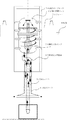
図1は本発明の一実施例の要部構成説明図、図2は図1の動作説明図である。
Hereinafter, the present invention will be described in detail with reference to the drawings.
FIG. 1 is a diagram illustrating the configuration of the main part of one embodiment of the present invention, and FIG. 2 is a diagram illustrating the operation of FIG.
図において、フロート31には、気体溶解タンク32とが搭載される。
加圧水中ポンプ33は、吸込ホース34に設けられている。
吸込ホース34と吐出ホース35とは、蛇腹管よりなる。
この場合は、吐出ホース35内に二重管状に吸込ホース34が配置されている。
In the figure, a gas dissolution tank 32 is mounted on the float 31.
The pressurized submersible pump 33 is provided in the
The
In this case, the
また、この場合は、加圧水中ポンプ33は、気体溶解タンク32内に配置されている。
また、この場合は、気体溶解タンク32は、気体溶解タンク32が上下に移動可能な浮沈ガイドレール36を介して、フロート31に取付けられている。
また、この場合は、潜没浮上装置(図示せず)がフロート31に設けられ、フロート31を潜没あるいは浮上する。
In this case, the pressurized submersible pump 33 is disposed in the gas dissolution tank 32.
Further, in this case, the gas dissolution tank 32 is attached to the float 31 via a floating
In this case, a submerged levitation device (not shown) is provided in the float 31 to submerge or float the float 31.
また、この場合は、図1に示す如く、気体溶解タンク32は、上下に二分割可能な二分割タンクが使用されている。
なお、気体溶解タンク32の上部に設けられ、気体溶解タンク32の上部の一部を開閉する開閉装置を設けても良い。
なお、この場合は、酸素発生装置(図示せず)は、陸上や別フロートに別置きされている。
なお、Wは水面を示す。
Further, in this case, as shown in FIG. 1, the gas dissolution tank 32 is a two-divided tank that can be divided into two vertically.
An opening / closing device that opens and closes a part of the upper portion of the gas dissolution tank 32 may be provided.
In this case, the oxygen generator (not shown) is separately placed on land or another float.
W represents the water surface.
以上の構成において、加圧水中ポンプ33により、吸込ホース34により水が吸入され、気体溶解タンク32に注入され、酸素発生装置よりの酸素が混入され、吐出ホース35より酸素がミキシングされた水が吐出される。
そして、水位の変動に対しては、フロート31が上下して対応し、吸込ホース34と吐出ホース35のホースの余分の長さは、蛇腹の伸縮により適切な長さに自動的に追従する。
In the above configuration, water is sucked by the
The float 31 moves up and down to cope with fluctuations in the water level, and the extra lengths of the
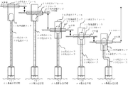
図2に、水位に対するフロート31と気体溶解タンク32と吸込ホース34,吐出ホース35との位置関係を示す。
図2(a)は最高水位状態A1、図2(b)は高水位状態A2、図2(c)は通常水位状態A3、図2(d)は低水位状態A4、図2(e)は最低水位状態A5を示す。
図2(c)の通常水位状態A3に対して、図2(b)の高水位状態A2では、蛇腹管34,35の伸長と気体溶解タンク32の下降で水位を吸収する。
FIG. 2 shows the positional relationship among the float 31, the gas dissolution tank 32, the
2A is the highest water level state A1, FIG. 2B is the high water level state A2, FIG. 2C is the normal water level state A3, FIG. 2D is the low water level state A4, and FIG. The lowest water level state A5 is shown.
In the high water level state A2 in FIG. 2B, the water level is absorbed by the extension of the
図2(b)の高水位状態A2に対して、図2(a)の最高水位状態A1では、ガイドレール36が下降して水位に追従する。
図2(c)の通常水位状態A3に対して、図2(d)の低水位状態A4では、蛇腹管34,35が短縮されて水位に追従する。
図2(d)の低水位状態A4に対して、図2(e)の最低水位状態A5では、蛇腹管34,35がたわんで水位に追従する。
In contrast to the high water level state A2 in FIG. 2B, in the highest water level state A1 in FIG. 2A, the
In the low water level state A4 in FIG. 2D, the
In the lowest water level state A5 in FIG. 2 (e), the
この結果、
気体溶解タンク32がフロート31に搭載されたので、フロート31の上下により、水位の変動に容易に追従できる気体溶解装置が得られる。
しかも、吸込ホース34と吐出ホース35とは、蛇腹管よりなるので、水位の変動に対して、ホースの伸縮により自動的に追従可能で、ホース長を適切に保つことが出来る気体溶解装置が得られる。
As a result,
Since the gas dissolution tank 32 is mounted on the float 31, a gas dissolution apparatus that can easily follow fluctuations in the water level can be obtained by moving the float 31 up and down.
In addition, since the
加圧ポンプとして、加圧水中ポンプ33が使用されたので、水中ポンプ33の部分が必ず水面下にあることになるので、揚程が稼げて効率が良い気体溶解装置が得られる。
効率が良いので、加圧水中ポンプ33が小型で済み、小型化が容易な気体溶解装置が得られる。
Since the pressurized submersible pump 33 is used as the pressurizing pump, the portion of the submersible pump 33 is always under the surface of the water, so that a gas dissolving apparatus with high head and high efficiency can be obtained.
Since the efficiency is high, the pressurized submersible pump 33 is small, and a gas dissolving device that can be easily downsized is obtained.
気体溶解タンク32がフロート31に搭載されるので、水中に殆どを容易に沈めることができるので水上の露呈面積が小さくでき、日射や風(水面は地上に比べて強風になり易い)の影響が少い気体溶解装置が得られる。
気体溶解タンク32がフロート31に搭載されるので、水中に殆どを容易に沈めることができるので、水上の露呈面積が小さくでき、美観、騒音対策に好適な気体溶解装置が得られる。
Since the gas dissolution tank 32 is mounted on the float 31, most of it can be easily submerged in the water, so that the exposed area on the water can be reduced, and the influence of solar radiation and wind (the water surface tends to be stronger than the ground) is affected. Less gas dissolution apparatus is obtained.
Since the gas dissolution tank 32 is mounted on the float 31, most of it can be easily submerged in water, so that the exposed area on the water can be reduced, and a gas dissolution apparatus suitable for aesthetics and noise countermeasures can be obtained.
吐出ホース35内に二重管状に吸込ホース34が配置されたので、吸込ホース34の吸込口を中心にして周囲に放射状に処理水が吐出できるので効率的な作業が可能な気体溶解装置が得られる。
吐出ホース36内に二重管状に吸込ホース34が配置されたので、吸込口と吐出口との相対位置を容易に正確に設定でき、水質浄化の必要な水深に酸素が効果的に供給できる気体溶解装置が得られる。
Since the
Since the
吐出ホース35内に二重管状に吸込ホース34が配置されたので、一本のホース状となり、取扱性が向上された気体溶解装置が得られる。
吐出ホース35内に二重管状に吸込ホース35が配置されたので、一本のホース状となり、強さが増し、場合によっては、フロートの繋留作業が不要な気体溶解装置が得られる。
吐出ホース35内に二重管状に吸込ホース35が配置されたので、一本のホース状となり、長さ、太さによる偏りがなく、設置安定が良好な気体溶解装置が得られる。
Since the
Since the suction hose 35 is arranged in a double tubular shape in the discharge hose 35, it becomes a single hose shape, the strength is increased, and in some cases, a gas dissolving device that does not require the anchoring operation of the float is obtained.
Since the suction hose 35 is arranged in a double tubular shape in the discharge hose 35, it becomes a single hose shape, and there is no deviation due to the length and thickness, and a gas dissolving device with good installation stability can be obtained.
加圧水中ポンプ33は、気体溶解タンク32内に配置されたので、加圧水中ポンプ33の占有面積を省くことができ、小型化が容易な気体溶解装置が得られる。
また、加圧水中ポンプ33は、気体溶解タンク32内に配置されたので、外置き加圧ポンプと配管を省くことが出来、小型化が容易な気体溶解装置が得られる。
Since the pressurized submersible pump 33 is disposed in the gas dissolution tank 32, the area occupied by the pressurized submersible pump 33 can be omitted, and a gas dissolution apparatus that can be easily downsized is obtained.
Further, since the pressurized submersible pump 33 is disposed in the gas dissolution tank 32, an external pressure pump and piping can be omitted, and a gas dissolution apparatus that can be easily downsized is obtained.
気体溶解タンク32は、気体溶解タンク32が上下に移動可能な浮沈ガイド36を介してフロート31に取付けられたので、吸込ホース34と吐出ホース35の蛇腹で追従出来ない水位変動は浮沈ガイドレール36が上下して吸収することができ、水位の変動に容易に追従出来る気体溶解装置が得られる。
Since the gas dissolution tank 32 is attached to the float 31 via a float /
フロート31に設けられフロート31を潜没浮上する潜没浮上装置が設けられたので、装置全体を水中に没することができ、美観、騒音対策に好適な気体溶解装置が得られる。
また、不使用時や湖面等の全面結氷時に、装置全体を水中に没することができ、美観、損傷防止に好適な気体溶解装置が得られる。
また、保守の際には、潜没装置により、空気圧を利用して、フロートの排水を行い、装置全体を浮上させて保守を行うことが出来、保守が容易に出来る気体溶解装置が得られる。
Since the submerged levitation device that is provided on the float 31 and levitates and floats on the float 31 is provided, the entire device can be submerged in water, and a gas dissolving device suitable for aesthetics and noise countermeasures can be obtained.
Moreover, the whole apparatus can be immersed in water at the time of non-use or icing of the whole surface of a lake, etc., and a gas dissolving apparatus suitable for aesthetics and damage prevention is obtained.
Further, in the maintenance, the submersion device can use the air pressure to drain the float, and the entire device can be lifted to perform maintenance, thereby obtaining a gas dissolving device that can be easily maintained.
気体溶解タンク32の上部に設けられ上部の一部を開閉する開閉装置が設けられれば、気体溶解タンク32の内部部品の保守点検が容易な気体溶解装置が得られる。
気体溶解タンク32は、上下に二分割可能な二分割タンクであるので、極めて、気体溶解タンクの保守点検が容易な気体溶解装置が得られる。
If an open / close device that opens and closes a part of the upper portion of the gas dissolution tank 32 is provided, a gas dissolution device that facilitates maintenance and inspection of internal components of the gas dissolution tank 32 can be obtained.
Since the gas dissolving tank 32 is a two-divided tank that can be divided into two parts in the vertical direction, a gas dissolving apparatus that is extremely easy to maintain and inspect the gas dissolving tank can be obtained.
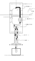
図3は本発明の他の実施例の要部構成説明図である。
本実施例においては、二重管状の吸込ホース34と吐出ホース35との上端部に設けられ吸込ホース34からの吸込口と吐出ホース35への吐出口とが異なる位置にある吐出吸込交差管41が設けられた気体溶解装置である。
この結果、ホース34,35の二重管状状態は確保出来、かつ、気体溶解タンク32と加圧水中ポンプ33との取付けの自由度が確保できる気体溶解装置が得られる。
FIG. 3 is an explanatory view showing the structure of the main part of another embodiment of the present invention.
In the present embodiment, the discharge suction cross pipe 41 provided at the upper end of the double
As a result, a gas dissolving device is obtained in which the double tubular state of the
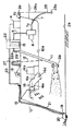
図4は本発明の他の実施例の要部構成説明図である。
本実施例においては、加圧水中ポンプ51は、気体溶解タンク32外に配置されている。
この結果、加圧水中ポンプ33は、気体溶解タンク32外に配置されたので、加圧水中ポンプ33の保守が容易な気体溶解装置が得られる。
FIG. 4 is an explanatory view showing the configuration of the main part of another embodiment of the present invention.
In the present embodiment, the pressurized submersible pump 51 is disposed outside the gas dissolution tank 32.
As a result, since the pressurized submersible pump 33 is disposed outside the gas dissolution tank 32, a gas dissolving apparatus that facilitates maintenance of the pressurized submersible pump 33 is obtained.
なお、以上の説明は、本発明の説明および例示を目的として特定の好適な実施例を示したに過ぎない。
したがって本発明は、上記実施例に限定されることなく、その本質から逸脱しない範囲で更に多くの変更、変形をも含むものである。
The above description merely shows a specific preferred embodiment for the purpose of explanation and illustration of the present invention.
Therefore, the present invention is not limited to the above-described embodiments, and includes many changes and modifications without departing from the essence thereof.
31 フロート
32 気体溶解タンク
33 加圧水中ポンプ
34 吸込ホース
35 吐出ホース
36 浮沈ガイドレール
41 吐出吸込交差管
51 加圧水中ポンプ
A1 最高水位状態
A2 高水位状態
A3 通常水位状態
A4 低水位状態
A5 最低水位状態
W 水面
31 Float 32 Gas dissolution tank 33 Pressurized
Claims (9)
前記気体溶解タンクが搭載されるフロートと、
吸込ホースに設けられた加圧水中ポンプと、
蛇腹管よりなる吸込ホースと吐出ホースと
を具備したことを特徴とする気体溶解装置。 An oxygen generator, a suction hose into which water is sucked, a gas dissolution tank into which water sucked from the suction hose is injected to mix oxygen from the oxygen generator, and the mixing connected to the gas dissolution tank In a gas dissolving device comprising a discharge hose from which discharged water is discharged,
A float on which the gas dissolution tank is mounted;
A pressurized water pump provided in the suction hose;
A gas dissolving apparatus comprising a suction hose and a discharge hose made of a bellows tube.
を特徴とする請求項1記載の気体溶解装置。 The gas dissolving device according to claim 1, wherein a suction hose is disposed in a double tubular shape in the discharge hose.
を特徴とする請求項1又は請求項2記載の気体溶解装置。 The gas dissolving device according to claim 1, wherein the pressurized submersible pump is disposed in the gas dissolving tank.
を特徴とする請求項1又は請求項2記載の気体溶解装置。 The gas dissolving apparatus according to claim 1, wherein the pressurized submersible pump is disposed outside the gas dissolving tank.
を特徴とする請求項1乃至請求項4の何れかに記載の気体溶解装置。 The gas dissolution apparatus according to any one of claims 1 to 4, wherein the gas dissolution tank is attached to the float via a floating guide rail that can move the gas dissolution tank up and down.
を具備したことを特徴とする請求項1乃至請求項5の何れかに記載の気体溶解装置。 The gas dissolution apparatus according to any one of claims 1 to 5, further comprising a submerged levitation device that is provided on the float and levitates and floats the float.
を具備したことを特徴とする請求項1乃至請求項6の何れかに記載の気体溶解装置。 The gas dissolving apparatus according to any one of claims 1 to 6, further comprising an opening / closing device provided at an upper part of the gas dissolving tank to open and close a part of the upper part.
を特徴とする請求項1乃至請求項7の何れかに記載の気体溶解装置。 The gas dissolving device according to any one of claims 1 to 7, wherein the gas dissolving tank is a two-divided tank that can be divided into two vertically.
を具備したことを特徴とする請求項2乃至請求項8の何れかに記載の気体溶解装置。
A discharge / suction cross pipe provided at an upper end portion of the double tubular suction hose and the discharge hose, wherein a suction port from the suction hose and a discharge port to the discharge hose are located at different positions. The gas dissolving apparatus according to any one of claims 2 to 8.
Priority Applications (1)
| Application Number | Priority Date | Filing Date | Title |
|---|---|---|---|
| JP2004160571A JP2005334835A (en) | 2004-05-31 | 2004-05-31 | Gas dissolving apparatus |
Applications Claiming Priority (1)
| Application Number | Priority Date | Filing Date | Title |
|---|---|---|---|
| JP2004160571A JP2005334835A (en) | 2004-05-31 | 2004-05-31 | Gas dissolving apparatus |
Publications (1)
| Publication Number | Publication Date |
|---|---|
| JP2005334835A true JP2005334835A (en) | 2005-12-08 |
Family
ID=35488967
Family Applications (1)
| Application Number | Title | Priority Date | Filing Date |
|---|---|---|---|
| JP2004160571A Pending JP2005334835A (en) | 2004-05-31 | 2004-05-31 | Gas dissolving apparatus |
Country Status (1)
| Country | Link |
|---|---|
| JP (1) | JP2005334835A (en) |
Cited By (8)
| Publication number | Priority date | Publication date | Assignee | Title |
|---|---|---|---|---|
| CN102265800A (en) * | 2011-06-24 | 2011-12-07 | 李宁生 | Oxygen-increasing machine for fish pond |
| CN102351332A (en) * | 2011-09-30 | 2012-02-15 | 安徽国祯环保节能科技股份有限公司 | Submersible aerator |
| KR101219784B1 (en) * | 2010-12-03 | 2013-01-09 | 주식회사 미주코리아 | Fountain with water quality purification function |
| CN103112960A (en) * | 2013-03-05 | 2013-05-22 | 湛江市科海科技有限公司 | Underwater aerator with improved structure |
| KR101580265B1 (en) * | 2015-03-23 | 2015-12-24 | (주)화인테크워터 | Dissolved air floatation apparatus equipped with nonpowered and auto air supply unit |
| CN105706994A (en) * | 2016-01-29 | 2016-06-29 | 陈培安 | Comprehensive oxygen aeration device for pond culture |
| JP2017023924A (en) * | 2015-07-21 | 2017-02-02 | 株式会社丸島アクアシステム | Surface layer water-intake circulation device |
| CN116256487A (en) * | 2023-05-15 | 2023-06-13 | 北京建筑大学 | Water purification treatment device with water quality detection function |
-
2004
- 2004-05-31 JP JP2004160571A patent/JP2005334835A/en active Pending
Cited By (9)
| Publication number | Priority date | Publication date | Assignee | Title |
|---|---|---|---|---|
| KR101219784B1 (en) * | 2010-12-03 | 2013-01-09 | 주식회사 미주코리아 | Fountain with water quality purification function |
| CN102265800A (en) * | 2011-06-24 | 2011-12-07 | 李宁生 | Oxygen-increasing machine for fish pond |
| CN102351332A (en) * | 2011-09-30 | 2012-02-15 | 安徽国祯环保节能科技股份有限公司 | Submersible aerator |
| CN103112960A (en) * | 2013-03-05 | 2013-05-22 | 湛江市科海科技有限公司 | Underwater aerator with improved structure |
| KR101580265B1 (en) * | 2015-03-23 | 2015-12-24 | (주)화인테크워터 | Dissolved air floatation apparatus equipped with nonpowered and auto air supply unit |
| JP2017023924A (en) * | 2015-07-21 | 2017-02-02 | 株式会社丸島アクアシステム | Surface layer water-intake circulation device |
| CN105706994A (en) * | 2016-01-29 | 2016-06-29 | 陈培安 | Comprehensive oxygen aeration device for pond culture |
| CN116256487A (en) * | 2023-05-15 | 2023-06-13 | 北京建筑大学 | Water purification treatment device with water quality detection function |
| CN116256487B (en) * | 2023-05-15 | 2023-07-04 | 北京建筑大学 | Water purification treatment device with water quality detection function |
Similar Documents
| Publication | Publication Date | Title |
|---|---|---|
| US20080277492A1 (en) | Fluid property regulator | |
| JP3925711B2 (en) | Oxygen supply device for water | |
| JP2011032940A (en) | Installation structure of hydraulic power generating apparatus | |
| JP2006264343A (en) | Generating enrichment floating body | |
| JP4990259B2 (en) | Air pumping equipment | |
| JP2005334835A (en) | Gas dissolving apparatus | |
| US20110013987A1 (en) | Guide apparatus for inducing downward flow of surface water | |
| JP2007021319A (en) | Aerator | |
| JP4849264B2 (en) | Seawater vertical circulator | |
| JP3208394B2 (en) | Oxygen dissolution method using water pressure | |
| JP2004249248A (en) | Water cleaning system | |
| JP5007468B2 (en) | Bubble jet air lift pump | |
| KR101502048B1 (en) | Purification device for river | |
| JP6389074B2 (en) | Seawater exchange device | |
| JP2004113920A (en) | Towing type diving gas dissolving apparatus | |
| JP2023019013A (en) | Aerator | |
| JP2005143403A (en) | Drifting installation for utilizing ocean deep water | |
| JP4793620B2 (en) | Gas dissolved water supply system | |
| JP2010095851A (en) | Navigation gate | |
| KR20090029433A (en) | Device for preventing red tide damage using bottom water | |
| KR200291592Y1 (en) | Fluid flow guide pipe with buoyant spheres which are induced near the upper surface of the fluid and provide fluid flow | |
| KR102241582B1 (en) | Water circulating device | |
| JP2008022813A (en) | Vessel for culturing shellfish and method for culturing shellfish | |
| JP2010046606A (en) | Seawater circulation apparatus | |
| JP2005290959A (en) | Low cost deep sea water intake, reservoir and transport technique |