JP2005318438A - Antenna device - Google Patents
Antenna device Download PDFInfo
- Publication number
- JP2005318438A JP2005318438A JP2004136327A JP2004136327A JP2005318438A JP 2005318438 A JP2005318438 A JP 2005318438A JP 2004136327 A JP2004136327 A JP 2004136327A JP 2004136327 A JP2004136327 A JP 2004136327A JP 2005318438 A JP2005318438 A JP 2005318438A
- Authority
- JP
- Japan
- Prior art keywords
- antenna device
- ground
- ground plane
- ground surface
- antenna
- Prior art date
- Legal status (The legal status is an assumption and is not a legal conclusion. Google has not performed a legal analysis and makes no representation as to the accuracy of the status listed.)
- Pending
Links
Images


Landscapes
- Aerials With Secondary Devices (AREA)
- Waveguide Aerials (AREA)
- Details Of Aerials (AREA)
- Support Of Aerials (AREA)
Abstract
Description
本発明は、パッチ型エレメントを用いたアンテナ装置に関し、特にバックローブを低減できるものに関する。 The present invention relates to an antenna device using a patch-type element, and more particularly to an antenna device that can reduce back lobes.
近年、モバイル放送(デジタルTV)の基地局や衛星波受信装置用として板状のパッチ型エレメントを用いたアンテナ装置が多用されている。このようなアンテナ装置は、例えば、グラウンド板と、このグラウンド板に対して離間して配置されたパッチ型エレメントとを備え、パッチ型エレメントに給電端子を接続することで送受信を行うものである(例えば特許文献1参照)。
上述したパッチ型エレメントを用いたアンテナ装置であると次のような問題があった。すなわち、このようなアンテナ装置を送信アンテナとして用いた場合、図8に示すように、メインビームMと反対向きに電波が照射されるバックローブBが少なからず発生する。このバックローブBは他のアンテナ装置の電波特性や電子機器の電気特性に悪影響を与える虞があるため、できるだけ低く抑える必要がある。バックローブBを低減するためには、グラウンド板を広くすればよいが、アンテナ装置が大型になるという問題がある。 The antenna device using the patch type element described above has the following problems. That is, when such an antenna device is used as a transmitting antenna, as shown in FIG. Since this back lobe B may adversely affect the radio characteristics of other antenna devices and the electrical characteristics of electronic equipment, it is necessary to keep the back lobe B as low as possible. In order to reduce the back lobe B, the ground plate may be widened, but there is a problem that the antenna device becomes large.
また、グラウンド板をその一辺の0.2倍程度の高さを有し、板面に対して垂直な壁部材で囲むことによりバックローブを多少低減させることができるが(図9参照)、壁部材を例えば0.3倍程度に高くしてもバックローブの低減効果はほどんど改善されない(図10参照)。このため、バックローブを所望のレベルまで低減させようとするとかなりの高さの壁部材が必要となり、小型化の障害となる。 Further, the back lobe can be somewhat reduced by surrounding the ground plate with a wall member having a height of about 0.2 times its one side and perpendicular to the plate surface (see FIG. 9). Even if the member is raised to about 0.3 times, the effect of reducing the back lobe is hardly improved (see FIG. 10). For this reason, if an attempt is made to reduce the back lobe to a desired level, a wall member having a considerably high height is required, which is an obstacle to miniaturization.
そこで本発明は、パッチ型エレメントを用いた場合に、装置を大型化することなく、バックローブを減少させ、他のアンテナ装置や電子機器への干渉を防止することができるアンテナ装置を提供することを目的としている。 Therefore, the present invention provides an antenna device that can reduce back lobes and prevent interference with other antenna devices and electronic devices without increasing the size of the device when a patch-type element is used. It is an object.
上記課題を解決し目的を達成するために、本発明のアンテナ装置は次のように構成されている。 In order to solve the above problems and achieve the object, the antenna device of the present invention is configured as follows.
(1)平面状のグラウンド面を有するグラウンド部材と、上記グラウンド面に対し平行に、かつ、所定距離だけ離間して設けられ、上記グラウンド面への投射領域が上記グラウンド面に含まれる板状のエレメント部材と、上記グラウンド面の外縁側に設けられ、上記グラウンド面及び上記エレメント部材の周囲を囲むとともに、上記グラウンド面から離間するにつれてその内壁面が上記エレメント部材の中心軸より離間する壁部材とを備えていることを特徴とする。 (1) A ground member having a planar ground surface and a plate-like member provided in parallel to the ground surface and spaced apart by a predetermined distance, and a projection area onto the ground surface is included in the ground surface An element member, and a wall member provided on an outer edge side of the ground surface, surrounding the ground surface and the periphery of the element member, and having an inner wall surface spaced from the central axis of the element member as the distance from the ground surface increases. It is characterized by having.
(2)上記(1)に記載されたアンテナ装置であって、上記グラウンド面、エレメント部材及び上記壁部材の上記エレメント部材側開口部は、いずれも矩形状に形成されていることを特徴とする。 (2) In the antenna device according to (1), the ground surface, the element member, and the element member side opening of the wall member are all formed in a rectangular shape. .
(3)上記(1)又は(2)に記載されたアンテナ装置であって、上記グラウンド部材と上記壁部材とは一体的に形成されていることを特徴とする。 (3) The antenna device according to (1) or (2), wherein the ground member and the wall member are integrally formed.
本発明によれば、パッチ型エレメントを用いた場合に、装置を大型化することなく、バックローブを減少させ、他のアンテナ装置や電子機器への干渉を防止することが可能となる。 According to the present invention, when patch type elements are used, it is possible to reduce back lobes and prevent interference with other antenna devices and electronic devices without increasing the size of the device.
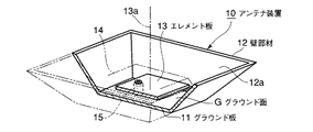
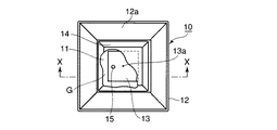
図1は本発明の第1の実施の形態に係るアンテナ装置10を一部切欠して示す斜視図、図2は同アンテナ装置10を一部切欠して示す平面図、図3は同アンテナ装置10を図2中X−X線で切断して矢印方向に見た断面図である。
FIG. 1 is a perspective view showing the
アンテナ装置10は、例えば70mm×70mmの矩形状のグラウンド面Gを有するグラウンド板11と、このグラウンド板11の外縁部に設けられた壁部材12と、グラウンド面Gに対し平行に、かつ、所定距離だけ離間して配置された例えば45mm×45mmの矩形板状のエレメント板13と、このエレメント板13を覆う樹脂材製のレドーム14とを備えている。なお、図1〜図3中15は外部からエレメント板13へ給電する給電部を示している。
The
壁部材12は、グラウンド板11に対し例えばθ=127°の角度で設けられており、グラウンド面Gから離れるにしたがってエレメント板13の中心線13aから離間する形状となっている。なお、壁部材12の上縁、すなわち開口部12aは例えば115mm×115mmの矩形状となっている。さらに、図3中L1は、壁部材12の開口部12aがグラウンド面Gからの離間するグラウンド面Gに平行な方向における長さ、L2は壁部材12のグラウンド面Gからの高さ、L3は壁部材12の傾斜方向の長さを示しており、例えばL1:L2:L3=3:4:5の比率に形成されていることが好ましい。
The
また、グラウンド板11及び壁部材12はアルミダイキャスト成形により一体的に形成されている。さらに、エレメント板13は例えば真鍮により形成されている。
The
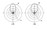
このように構成されたアンテナ装置10では、エレメント板13に給電を行うことにより送信を行う。なお、動作周波数は2.5GHzである。また、偏波は直線偏波である。このとき、電波特性は図4に示すようなものとなる。図4に示すように、E面、H面共にメインビームMに比べてバックローブBが小さいことがわかる。バックローブBが小さいので、他のアンテナ装置や電子機器への影響を最小限に抑えることができる。
In the
なお、グラウンド面Gとエレメント板13との間には、空気層が形成されているが、空気層以外の誘電体を配置するようにしてもよい。空気層を用いた場合には、比誘電率が1であり、製品ばらつきが無く、利得が大きいというメリットがある。また、比誘電率が1以上の誘電体を用いた場合には、サイズを小さくできるというメリットがある。
Although an air layer is formed between the ground plane G and the
上述したように本実施の形態に係るアンテナ装置10によれば、パッチ型のエレメント板13を用いた場合であっても、装置を大型化することなく、バックローブを効果的に低減することができる。このため、他のアンテナ装置や電子機器への干渉を防止することが可能となる。また、設置スペースが限られる場合であっても、アンテナ装置10を用いることが可能となる。
As described above, according to the
図5は、上述したアンテナ装置10を、リピータシステムアンテナ装置20に組み込んだ例を示す側面図である。リピータシステムアンテナ装置20は、支持台21と、この支持台21にブラケット22を介して取り付けられたアンテナ装置10と、ブラケット23を介して取り付けられたアンテナ装置30と、アンテナ装置30で受信した信号を増幅してアンテナ装置10に送るアンプ装置40とを備えている。
FIG. 5 is a side view showing an example in which the above-described
アンテナ装置10は、前述したように地上側送信アンテナであり、アンテナ装置30は衛星波受信アンテナである。リピータシステムアンテナ装置20では、アンテナ装置30で放送衛星から受信した信号をアンプ装置40で増幅し、アンテナ装置10に送る。アンテナ装置10とアンテナ装置30は近接しているため、アンテナ装置10からのバックローブが大きいと、アンテナ装置30の受信信号に干渉し、アンプ装置40が飽和する虞がある。しかしながら、前述したようにアンテナ装置10のバックローブBは十分に低減されているため、アンテナ装置10とアンテナ装置30とを電気的に分離、すなわち、アイソレーションを良くすることができることから、アンテナ装置30の受信信号に影響を与えることはない。
As described above, the
上述したようにリピータシステムアンテナ装置20においても、アンテナ装置10を組み込むことにより、装置を大型化することなく、バックローブを効果的に低減することができ、受信側のアンテナ装置30やアンプ装置40への干渉を最小限に抑えることができる高品質なリピータサービスを提供することが可能となる。
As described above, also in the repeater
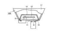
図6は、上述したアンテナ装置10の第1変形例に係るアンテナ装置10Aを一部切欠して示す側面図である。本アンテナ装置10Aでは、グラウンド面Gの廻りに樹脂部材16が形成され、この樹脂部材16に対して上述した壁部材12と同様の壁部材17が形成されている。本第1変形例に係るアンテナ装置10Aにおいても上述したアンテナ装置10と同様の効果を得ることができる。
FIG. 6 is a side view showing a part of the
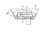
図7は、上述したアンテナ装置10の第2変形例に係るアンテナ装置10Bを一部切欠して示す側面図である。本アンテナ装置10Bでは、グラウンド板11の下側からエレメント板13側に向けて上述した壁部材12と同様の壁部材18が形成されている。すなわち、壁部材18とグラウンド板11とは別部材となっている。さらに、壁部材18により、グラウンド板11及びエレメント板13が囲まれるように配置されている。本第2変形例に係るアンテナ装置10Bにおいても上述したアンテナ装置10と同様の効果を得ることができる。
FIG. 7 is a side view showing a part of the
なお、上述した壁部材12,17,18はいずれも金属材製であることが好ましいが、例えば同等の効果が得られるのであれば他の材質のものでもよい。例えば、図6及び図7に示した例においては、壁部材17,18を軽量化のために樹脂で形成し、その表面に金属箔、金属メッキ、金属粉を付着させるようにしてもよい。
The
なお、本発明は前記実施の形態に限定されるものではない。すなわち、上述した実施の形態では、グラウンド板を矩形状としたが、例えば円形であっても構わない。この場合、壁部材は円筒の端部側を広げたラッパ状となる。また、送信アンテナのバックローブを低減させるものとして説明したが、受信アンテナのバックローブを低減させるために用いても良い。この他、本発明の要旨を逸脱しない範囲で種々変形実施可能であるのは勿論である。 The present invention is not limited to the above embodiment. That is, in the above-described embodiment, the ground plate is rectangular, but may be circular, for example. In this case, the wall member has a trumpet shape in which the end side of the cylinder is widened. Moreover, although it demonstrated as what reduces the back lobe of a transmitting antenna, you may use in order to reduce the back lobe of a receiving antenna. Of course, various modifications can be made without departing from the scope of the present invention.
10,10A,10B…アンテナ装置、11…グラウンド板、12,17,18…壁部材、12a…開口部、13…エレメント板、20…リピータシステムアンテナ装置、30…アンテナ装置、40…アンプ装置。
DESCRIPTION OF
Claims (3)
上記グラウンド面に対し平行に、かつ、所定距離だけ離間して設けられ、上記グラウンド面への投射領域が上記グラウンド面に含まれる板状のエレメント部材と、
上記グラウンド面の外縁側に設けられ、上記グラウンド面及び上記エレメント部材の周囲を囲むとともに、上記グラウンド面から離間するにつれてその内壁面が上記エレメント部材の中心軸より離間する壁部材とを備えていることを特徴とするアンテナ装置。 A ground member having a planar ground surface;
A plate-like element member that is provided in parallel to the ground surface and spaced apart by a predetermined distance, and a projection area onto the ground surface is included in the ground surface;
A wall member that is provided on an outer edge side of the ground surface, surrounds the periphery of the ground surface and the element member, and has an inner wall surface that is separated from the central axis of the element member as the distance from the ground surface increases. An antenna device characterized by that.
Priority Applications (1)
| Application Number | Priority Date | Filing Date | Title |
|---|---|---|---|
| JP2004136327A JP2005318438A (en) | 2004-04-30 | 2004-04-30 | Antenna device |
Applications Claiming Priority (1)
| Application Number | Priority Date | Filing Date | Title |
|---|---|---|---|
| JP2004136327A JP2005318438A (en) | 2004-04-30 | 2004-04-30 | Antenna device |
Publications (2)
| Publication Number | Publication Date |
|---|---|
| JP2005318438A true JP2005318438A (en) | 2005-11-10 |
| JP2005318438A5 JP2005318438A5 (en) | 2007-06-14 |
Family
ID=35445379
Family Applications (1)
| Application Number | Title | Priority Date | Filing Date |
|---|---|---|---|
| JP2004136327A Pending JP2005318438A (en) | 2004-04-30 | 2004-04-30 | Antenna device |
Country Status (1)
| Country | Link |
|---|---|
| JP (1) | JP2005318438A (en) |
Cited By (5)
| Publication number | Priority date | Publication date | Assignee | Title |
|---|---|---|---|---|
| JP2014171091A (en) * | 2013-03-04 | 2014-09-18 | Nec Corp | Foldable reflector |
| CN107978838A (en) * | 2017-11-23 | 2018-05-01 | 广东通宇通讯股份有限公司 | Antenna for base station and the coaxial mounting platform of low-and high-frequency oscillator |
| KR101987393B1 (en) * | 2017-12-07 | 2019-06-13 | 주식회사 한신 | Case-integrated dual-pole antenna |
| JP2021523607A (en) * | 2018-05-10 | 2021-09-02 | ケイエムダブリュ インコーポレーテッドKmw Inc. | Dually polarized antenna and antenna array |
| WO2023047954A1 (en) * | 2021-09-22 | 2023-03-30 | 株式会社ヨコオ | Patch antenna, and antenna device |
-
2004
- 2004-04-30 JP JP2004136327A patent/JP2005318438A/en active Pending
Cited By (7)
| Publication number | Priority date | Publication date | Assignee | Title |
|---|---|---|---|---|
| JP2014171091A (en) * | 2013-03-04 | 2014-09-18 | Nec Corp | Foldable reflector |
| CN107978838A (en) * | 2017-11-23 | 2018-05-01 | 广东通宇通讯股份有限公司 | Antenna for base station and the coaxial mounting platform of low-and high-frequency oscillator |
| KR101987393B1 (en) * | 2017-12-07 | 2019-06-13 | 주식회사 한신 | Case-integrated dual-pole antenna |
| JP2021523607A (en) * | 2018-05-10 | 2021-09-02 | ケイエムダブリュ インコーポレーテッドKmw Inc. | Dually polarized antenna and antenna array |
| US11289805B2 (en) | 2018-05-10 | 2022-03-29 | Kmw Inc. | Dual polarized antenna and antenna array |
| JP7171760B2 (en) | 2018-05-10 | 2022-11-15 | ケイエムダブリュ インコーポレーテッド | Dual polarized antennas and antenna arrays |
| WO2023047954A1 (en) * | 2021-09-22 | 2023-03-30 | 株式会社ヨコオ | Patch antenna, and antenna device |
Similar Documents
| Publication | Publication Date | Title |
|---|---|---|
| CA2737225C (en) | Multilayer antenna arrangement | |
| JP4121424B2 (en) | Dual polarized antenna | |
| US6646618B2 (en) | Low-profile slot antenna for vehicular communications and methods of making and designing same | |
| US10096893B2 (en) | Patch antennas | |
| JP4143844B2 (en) | Antenna device | |
| WO2012077389A1 (en) | Antenna device | |
| US8674884B2 (en) | Dual-band circularly polarized antenna | |
| JP2008061175A (en) | Composite antenna device | |
| JP2004343531A (en) | Compound antenna | |
| JPH11511614A (en) | Low internal modulation electromagnetic feed antenna for mobile phone | |
| JP2004242306A (en) | Coupled antenna system for multiple radio communication services for vehicle | |
| US8089410B2 (en) | Dual-band antenna | |
| US8514137B2 (en) | Composite antenna device | |
| JP2010161436A (en) | Composite antenna element | |
| KR101779593B1 (en) | Patch antenna | |
| JP6181498B2 (en) | Antenna device | |
| JP2011077827A (en) | Antenna device | |
| US20040201523A1 (en) | Patch antenna apparatus preferable for receiving ground wave and signal wave from low elevation angle satellite | |
| US7042399B2 (en) | Patch antenna having a non-feeding element formed on a side surface of a dielectric | |
| JP2005318438A (en) | Antenna device | |
| EP1186073A1 (en) | Patch antenna and a communication device including such an antenna | |
| JP2006121219A (en) | Multi-resonance planar antenna | |
| JP2003347838A (en) | Antenna device | |
| US6999029B2 (en) | Antenna apparatus including a flat-plate radiation element and improved in radiation characteristic | |
| JP4302561B2 (en) | Antenna device and gap filler system |
Legal Events
| Date | Code | Title | Description |
|---|---|---|---|
| A521 | Written amendment |
Free format text: JAPANESE INTERMEDIATE CODE: A523 Effective date: 20070427 |
|
| A621 | Written request for application examination |
Effective date: 20070427 Free format text: JAPANESE INTERMEDIATE CODE: A621 |
|
| A977 | Report on retrieval |
Free format text: JAPANESE INTERMEDIATE CODE: A971007 Effective date: 20090127 |
|
| A131 | Notification of reasons for refusal |
Free format text: JAPANESE INTERMEDIATE CODE: A131 Effective date: 20090203 |
|
| A02 | Decision of refusal |
Free format text: JAPANESE INTERMEDIATE CODE: A02 Effective date: 20090616 |