JP2005296321A - Device and method for inspecting fire fighting equipment - Google Patents
Device and method for inspecting fire fighting equipment Download PDFInfo
- Publication number
- JP2005296321A JP2005296321A JP2004116631A JP2004116631A JP2005296321A JP 2005296321 A JP2005296321 A JP 2005296321A JP 2004116631 A JP2004116631 A JP 2004116631A JP 2004116631 A JP2004116631 A JP 2004116631A JP 2005296321 A JP2005296321 A JP 2005296321A
- Authority
- JP
- Japan
- Prior art keywords
- display
- screen
- control circuit
- displayed
- inspection
- Prior art date
- Legal status (The legal status is an assumption and is not a legal conclusion. Google has not performed a legal analysis and makes no representation as to the accuracy of the status listed.)
- Granted
Links
Images


Landscapes
- Fire-Extinguishing By Fire Departments, And Fire-Extinguishing Equipment And Control Thereof (AREA)
Abstract
Description
本発明は、二酸化炭素消火設備やハロン消火設備などを代表とするガス系消火設備、放水型スプリンクラ消火設備などを代表とする水系消火設備など各種消火設備の点検装置及び点検方法に関する。 The present invention relates to an inspection apparatus and an inspection method for various fire extinguishing equipment such as a gas fire extinguishing equipment typified by carbon dioxide fire extinguishing equipment and a halon fire extinguishing equipment, and a water fire extinguishing equipment typified by a water discharge type sprinkler fire extinguishing equipment.
消火設備はその機能を適正に維持するため、消防法にて定期点検及び報告が義務付けられている。またこの点検項目の中の各試験を自動的に行い、試験結果を一時的に記憶し、記憶した試験結果を必要に応じてディスプレイに表示したり、プリントアウトできる自動点検機能付きの消火設備が既に知られている(例えば、特許文献1,2参照。)。
消火設備には一般の設備機器と同様に設置後の時間経過とともに劣化し寿命のある部品も使用されている。消火設備を適正な状態に維持管理するためには、故障が発生した時点ではなく、予防保全の観点から故障する前に寿命部品の交換を行うことが必要である。このために寿命部品の中には部品業界・部品メーカーが寿命年数や交換時期を定めているものもある。しかしながら、部品寿命は設置環境によって左右されるため、設置環境に応じた適正時期に寿命部品の交換を行うことは非常に困難である。 As in general equipment, fire extinguishing equipment uses parts that deteriorate with the passage of time after installation and have a long life. In order to maintain and manage the fire extinguishing equipment in an appropriate state, it is necessary to replace the life parts before the failure from the viewpoint of preventive maintenance, not at the time when the failure occurs. For this reason, some parts with a limited life span and parts manufacturers have determined the life years and replacement periods. However, since the life of parts depends on the installation environment, it is very difficult to replace the life parts at an appropriate time according to the installation environment.
本発明は寿命がありその寿命が設置環境によって左右される寿命部品について、設置環境に応じた適正交換時期を予測し得る消火設備の点検装置及び点検方法を提供することを目的としている。 An object of the present invention is to provide a fire extinguishing equipment inspection device and inspection method capable of predicting an appropriate replacement time according to an installation environment for a life part whose life is affected by the installation environment.
本出願人は寿命部品は劣化が進むにつれて電流や電圧、消費電力などが、あるものについては徐々に上がり、あるものについては徐々に下がり、変化することに着目し本発明を提案した。 The present applicant has proposed the present invention by paying attention to the fact that current, voltage, power consumption, etc., gradually increase for some components and gradually decrease and change for certain components as the life components deteriorate.
上記目的を達成する本発明の消火設備の点検装置は、消火設備の点検の都度、寿命部品の電流・電圧の一方又は両方をデータとして記憶し蓄積するデータ記憶蓄積手段を備えたことを特徴とする。 The fire extinguishing equipment inspection device of the present invention that achieves the above object is characterized by comprising data storage and accumulating means for memorizing and accumulating one or both of current and voltage of a life component as data each time the fire extinguishing equipment is inspected. To do.
また、本発明の消火設備の点検方法は、消火設備の点検の都度、寿命部品の電流・電圧の一方又は両方をデータとして記憶・蓄積しておき、その蓄積データを利用して寿命部品の交換時期を予測した上で点検を行うことを特徴とする。 The fire extinguishing equipment inspection method of the present invention stores and accumulates one or both of the current and voltage of a life part as data each time the fire extinguishing equipment is inspected, and replaces the life part using the accumulated data. It is characterized by performing inspection after predicting the time.
本発明の消火設備の点検装置及び点検方法によれば、消火設備の設置時から現時点まで(最大更新時まで)、例えば、6ヶ月に1回定期的に寿命部品の電流・電圧の一方又は両方がデータとして記憶され蓄積されて行き、個々の消火設備が、設置時から現時点までの(最大更新時までの)履歴のデータベースを持つこととなる。そこで、ある寿命部品について、例えば、半年前の点検時のデータと1年前の点検時のデータとを比較し、その変化量を見ることによって、寿命部品の劣化程度が判別でき、これに基づいて設置環境に応じた交換時期が予測できる。この結果、設置環境に応じた適正時期に寿命部品の交換を行うことができ、消火設備を適正な状態で維持管理できる。要するに、消火設備を予知保全を行うことができ、またこの予知保全により定期点検の効率や精度・信頼性も高めることができるという効果を奏する。 According to the inspection apparatus and inspection method for fire extinguishing equipment of the present invention, from the time of installation of the fire extinguishing equipment to the present time (until the maximum update time), for example, once or every six months, one or both of the current and voltage of the life component Are stored and accumulated as data, and each fire extinguishing equipment has a history database from the time of installation to the present time (up to the maximum update time). Therefore, for a certain life component, for example, by comparing the data at the time of inspection six months ago with the data at the inspection one year ago and looking at the amount of change, the degree of deterioration of the life component can be determined. The replacement time according to the installation environment can be predicted. As a result, life parts can be replaced at an appropriate time according to the installation environment, and the fire extinguishing equipment can be maintained and managed in an appropriate state. In short, it is possible to carry out predictive maintenance of the fire extinguishing equipment, and it is possible to improve the efficiency, accuracy and reliability of periodic inspections by this predictive maintenance.
以下、本発明の実施の形態を図面に基づいて説明する。図1は消火設備の一例を示すシステム構成図である。本実施形態ではガス系の消火剤を使用するガス系消火設備Sを示している。図1において、1は二酸化炭素、窒素、アルゴンの不活性ガス単体又は混合体で構成されるイナート系(不活性ガス系)消火剤やハロゲン元素(臭素、フッ素など)、炭素、水素の化合物であるフッ素系(ハロゲン化物系)消火剤などを充填する消火剤貯蔵容器で、消火剤は容器弁2(開放器付き)から導管3を介して集合配管4へと導かれ、集合配管4から分岐配管5を介して、例えば電算機室、通信機室、駐車場、美術品収蔵庫などの各防護区画6に設置された各噴射ヘッド7へと導かれる。集合配管4の途中には安全装置8が設けられ、安全装置8の二次側には閉止弁9が設けられ、閉止弁9の二次側の集合配管4から各分岐配管5がそれぞれ選択弁10を介して分岐接続される。11は二酸化炭素などの起動用ガスを充填する起動用ガス容器で、起動用ガスは容器弁12(開放器付き)から導管13を介して選択弁10の起動ガス導入口へと導かれ、選択弁10の排気口から導管14及び逆止弁15を介して消火剤貯蔵容器1の容器弁2に着脱自在に取り付けられる開放器の起動ガス導入口へと導かれる。16は中央監視室17などに配備される制御盤、18は防護区画6の出入り口19付近に配備される操作箱(手動式起動装置)、21,22は異なる種類のアナログ火災感知器、23は放出表示灯(充満表示灯)、24はスピーカー(音声警報装置)、25は電動シャッター、26は各起動用ガス容器11の容器弁12に着脱自在に取り付ける開放器のソレノイド、27は各選択弁10の二次側の分岐配管5の途中に設ける圧力スイッチ、30は各防護区画6に接続され換気口にダンパー31を有する換気ダクト、32は各防護区画6の分岐配管5から導管33を介して消火剤を導くピストンレリーザである。
Hereinafter, embodiments of the present invention will be described with reference to the drawings. FIG. 1 is a system configuration diagram illustrating an example of a fire extinguishing facility. In this embodiment, the gas fire extinguishing equipment S which uses a gas fire extinguisher is shown. In FIG. 1, 1 is an inert (inert gas) extinguishing agent composed of carbon dioxide, nitrogen or argon inert gas alone or a mixture thereof, a halogen element (bromine, fluorine, etc.), a compound of carbon, hydrogen. A fire extinguisher storage container filled with a certain fluorine-based (halide-based) fire extinguisher. The fire extinguisher is led from the container valve 2 (with opener) to the collecting
図2は制御回路20の概略を示すブロック図である。制御回路20はマイクロコンピューターで構成され、制御盤16に配備される。この制御回路20には、制御盤16に配備する火災灯、放出灯、自動灯、手動灯、電源灯、操作箱扉開灯、起動灯、故障灯、スイッチ注意灯、閉止弁開灯、閉止弁閉灯などの盤内表示灯40、自・手動切替スイッチ、警報停止スイッチ、ブザー停止スイッチ、システム復旧スイッチ、機器停止移報停止スイッチなどの盤内操作スイッチ41、放出遅延時間を設定する放出遅延時間設定器42及びその設定値を表示するとともに設定された放出遅延時間をカウントダウン表示するセブンセグメント式のカウントダウン表示器43、ブザー46、電話ジャック(図示せず)、点検手順表示用のタッチパネル付き表示装置47と、操作箱16に配備する火災灯、放出灯、起動灯、自動灯、手動灯、電源灯、点検注意灯、閉止弁閉灯などの操作箱表示灯48、設定された放出遅延時間をカウントダウン表示するセブンセグメント式のカウントダウン表示器49、自・手動切替スイッチ、扉開スイッチ、起動スイッチ、非常停止スイッチなどの操作箱操作スイッチ50、電話ジャック(図示せず)と、各防護区画6に配備される2種類の各火災感知器21,22、放出用表示灯23、スピーカー24、シャッターモータ51と、開放器ソレノイド26と、圧力スイッチ27と、閉止弁9の開(検出)スイッチ52及び閉(検出)スイッチ53と、蓄電設備付きの電源回路54と、地絡検出回路や回路異常検出回路(図示せず)と、防護対象の外部機器や換気ファン(図示せず)などが接続される。
FIG. 2 is a block diagram showing an outline of the
次に、消火設備Sの手動起動と自動起動に動作について説明する。まず、手動起動(制御盤16及び操作箱18の自・手動切替スイッチがともに人為的に手動側に切り替えられ、制御回路20が手動灯の点灯による手動表示を行う手動モード状態)の場合は、操作箱18の扉が人為的に開かれ、これを制御回路20が扉開スイッチのオン信号で検出すると、その制御回路20が操作箱扉開灯の点灯による操作箱開表示、外部機器停止移報表示を行うとともに、火災灯の点灯による火災表示及びスピーカ24により音声による退避警報を行う。次いで、防護区画6内の人の退避を確認した後、起動スイッチを人為的にオン操作すると、制御回路20が起動灯の点灯による起動表示、スピーカ24による音声による起動警報、放出遅延用タイマの起動、シャッターモータ51を作動させてのシャッター25の閉鎖、換気ファンの停止、外部機器の停止などを行う。次いで、放出遅延時間内に人為的な非常停止スイッチのオン操作がない場合、制御回路20が放出遅延時間経過後に起動用ガス容器11の容器弁12の開放器ソレノイド26を作動させる。このソレノイド26の作動によって起動用ガスが放出しそのガス圧力で選択弁10が開放され、消火剤貯蔵容器1の容器弁2もこの開放器を介して開放される。消火剤貯蔵容器1の容器弁2の開放によって消火剤が噴射ヘッド7から防護区画6内に放出され、そのガス圧力でピストンレリーザ32が作動してダンパー31が閉鎖されるとともに、圧力スイッチ27が作動し制御回路20が放出灯の点灯及び放出表示灯23の点滅による消火剤放出表示を行う。
Next, operations will be described for manual activation and automatic activation of the fire extinguishing equipment S. First, in the case of manual activation (the manual mode state in which both the
一方、自動起動(制御盤16及び操作箱18の自・手動切替スイッチがともに人為的に自動側に切り替えられ、制御回路20が自動灯の点灯による自動表示を行う自動モード状態)の場合は、制御回路20が1種類の火災感知器21の作動(火災検知)に基づいて外部機器停止移報表示を行うとともに、火災灯の点滅による火災表示を行い、もう1種類の火災感知器22の作動に基づいて、すなわち2種類の火災感知器21,22のアンド動作によって火災灯の点灯による火災表示及びスピーカ24により音声による退避警報を行う。次いで、制御回路20が起動灯の点灯による起動表示、スピーカー24により音声による起動警報、放出遅延用タイマの起動、シャッターモータ51を作動させてのシャッター25の閉鎖、換気ファンの停止、外部機器の停止などを行う。次いで、放出遅延時間内に人為的な非常停止スイッチのオン操作がない場合、制御回路20が放出遅延時間経過後に起動用ガス容器11の容器弁12の開放器ソレノイド26を作動させる。これ以降の動作は手動起動の場合と同じである。
On the other hand, in the case of automatic activation (automatic mode in which both the
以上のように、制御回路20は操作箱18からのスイッチ操作に基づいて消化設備Sを起動させる手動起動機能と、各火災感知器21,22の動作に基づいて消火設備Sを起動させる自動起動機能を有するとともに、制御回路20は消火設備Sの機能を適正に維持するために定期的に行われる点検に際して、その点検項目を手順ごとにタッチパネル付き表示装置47に表示する点検手順表示機能を有し、次にこの点検手順表示機能について説明する。
As described above, the
すなわち、前記制御回路20を、消火設備Sの点検項目を手順毎に表示装置47に表示する表示手段と、表示装置47に表示された点検項目の実行をタッチパネルの人為的入力操作に基づいて判別する確認手段と、表示装置47に表示する点検項目をその実行確認に基づいて順番に切り替える点検項目切り替え手段として機能させるための点検手順表示プログラムを備える。またタッチパネル付き表示装置47を制御盤16とは別体に構成し、消火設備Sの点検時に制御回路20に接続して使用可能である。タッチパネル付き表示装置47と制御回路20との接続は、タッチパネル付き表示装置47の装着部を制御盤16の盤面に設け、その装着部にタッチパネル付き表示装置47を装着し、タッチパネル付き表示装置47と制御回路20とを接続端子で接続する他、制御盤16に制御回路20に接続された接続端子を設け、タッチパネル付き表示装置47と制御回路20とを接続ケーブルを介して有線で接続したり、タッチパネル付き表示装置47と制御回路20の間に通信回路を構成し、タッチパネル付き表示装置47と制御回路20とを無線で接続することも可能である。
That is, the
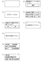
図3はタッチパネル付き表示装置47の表示例を示す図である。
(a)は初期画面で、当該消火設備Sの点検開始当初タッチパネル付き表示装置47は消灯し何も表示されておらず画面全体がスイッチになっており、点検者が初期画面に触れることによりこれを制御回路20が判別(認識)しタッチパネル付き表示装置36を点灯させ(b)に示す名称表示画面に切り替えて当該消火設備点検用プログラムの製造販売者の名称やプログラム名などを表示する。次いで点検者が名称表示画面(b)に触れる(画面全体がスイッチになっている。)ことによりこれを制御回路20が判別し(c)に示す点検確認画面に切り替える。この点検確認画面では「YES」の文字表示がある枠内と「NO」の文字表示がある枠内がスイッチになっており、点検者が「YES」の文字表示がある枠内を押すことによりこれを制御回路20が判別し当該消火設備Sの点検を開始する。(点検開始操作)
(d)は機器の動作指示画面で、文字だけにより機器の操作を促す画面が表示された時は、その表示内容に沿った操作を点検者が行うとこれを制御回路20が判別し次画面への切り替えを行う。この表示例(d)の画面が表示された時は、点検者が閉止弁9を閉じるとこれを制御回路20が閉止弁閉スイッチ53により判別し次画面への切り替えを行う。
(e)(f)は制御盤・操作箱の表示、外部機器動作確認画面で、制御盤・操作箱・外部機器という文字の下に各種文字表示がある複数の枠内がスイッチになっており、この画面が表示された時は、各枠内に表示されている文字の制御盤・操作箱の表示又は外部機器の動作を点検者が確認し文字表示がある枠内を押すことによりこれを制御回路20が判別しその文字表示を消し(誤って押した場合はもう一度押すことで文字は再度表示される。)、全ての文字表示を消灯させた後、点検者が「確認」の文字表示がある枠内を押すことによりこれを制御回路20が判別し次画面への切り替えを行う(点灯箇所がある場合、「確認」の文字表示がある枠内を押しても次画面に切り替えない。)。この表示例(e)の画面が表示された時は、制御盤16のスイッチ注意灯・放出灯の点灯とブザーの鳴動、外部機器、スピーカー24の鳴動と放出表示灯23などの点滅を点検者がそれぞれ確認し「SW注」・「放出」・「BZ鳴」・「音警報」・「充満表」の各文字表示がある各枠内を押すことによりこれを制御回路20が判別しその各文字表示を消し、全ての文字表示を消した後、点検者が「確認」の文字表示がある枠内を押すことによりこれを制御回路20が判別し次画面への切り替えを行う。
(g)は機器の動作指示と確認スイッチがある場合の画面で、動作指示と確認スイッチが表示されている画面が表示された時は、点検者が機器を作動させた後「確認」の文字表示がある枠内を押すことによりこれを制御回路20が判別し次画面への切り替えを行う(機器を動作させずに「確認」の文字表示がある枠内を押しても次画面に切り替える。)。この表示例(g)の画面が表示された時は、点検者が起動用ガス容器11の容器弁12の開放器26のキーパーを外した後「確認」の文字表示がある枠内を押すことによりこれを制御回路20が判別し次画面への切り替えを行う。
(h)は試験項目選択画面で、「試験項目を選択してください。」という文字の下に各種試験項目の文字表示がある複数の枠内がスイッチになっており、この画面が表示された時は、点検者が今から実施しようとする試験項目の文字表示がある枠内を押すことによりこれを制御回路20が判別しその選択された試験を行うか否かの試験確認画面への切り替えを行う。この表示例(h)の試験項目選択画面(1頁目)が表示されており表示外の試験を行う時は、点検者が「次項」の文字表示がある枠内を押すことによりこれを制御回路20が判別し次の試験項目選択画面(2頁目)への切り替えを行う。
表示例(i)の破線で示すように、表示画面の右上すみ部と左上すみ部は表示画面上には何も表示しない隠れスイッチになっており、点検の途中でその試験を中止する場合、点検者が所定の一側(本実施例では右側)の隠れスイッチ部を押すことによりこれを制御回路20が判別し復旧確認画面への切り替えを行う。その復旧確認画面に表示される「YES」を選択し画面の指示にしたがって機器などを点検前の状態に復旧して当該消火設備Sの点検を中止する。点検者による点検中止操作が行われた場合、点検を中止するより続行した方が早く復旧できると制御回路20が判別した時は前記隠れスイッチ部を押しても復旧確認画面に切り替えない。他方、点検者が所定の一側(本実施例では左側)の隠れスイッチ部を所定回数押すことによりこれを制御回路20が判別し前記初期画面(a)への切り替えを行い、強制的に点検を終了する。この場合,決められた手順通りに機器などを点検前の状態に復旧する必要がある。
FIG. 3 is a diagram showing a display example of the
(A) is an initial screen. When the inspection of the fire extinguishing equipment S is started, the
(D) is an operation instruction screen for the device. When a screen for prompting the operation of the device is displayed only by characters, the
(E) and (f) are control panel / operation box display and external device operation confirmation screens. There are switches in various frames where various characters are displayed under the letters “control panel / operation box / external device”. When this screen is displayed, check by checking the display of the control panel / operation box of the characters displayed in each frame or the operation of the external device, and pressing the inside of the frame with the character display. The
(G) is the screen when there is a device operation instruction and a confirmation switch. When a screen displaying the operation instruction and the confirmation switch is displayed, the word “confirm” is displayed after the inspector operates the device. By pressing the inside of the frame with the display, the
(H) is the test item selection screen. There are switches in the multiple frames with the text display of various test items under the words “Please select the test item.” This screen is displayed. When the checker presses the frame in which the character of the test item to be carried out is pressed, the
As shown by the broken line in the display example (i), the upper right corner and the upper left corner of the display screen are hidden switches that display nothing on the display screen, and when the test is stopped during the inspection, When the inspector presses a hidden switch portion on a predetermined side (right side in this embodiment), the
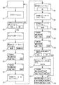
図4は点検手順表示プログラムによる制御回路20の動作概要を説明するフローチャートである。
制御回路20は、初期画面(初期状態)から点検開始確認画面を表示し、この点検開始画面にて点検者に当該消火設備Sの点検を行うか否かの確認を行い、その確認後に点検準備のための動作(手順毎の画面表示)を行う。次いで点検準備動作完了後に試験項目選択画面を表示し、この試験項目選択画面にて点検者に今からどの項目の試験を実施するのかの確認を行う。次いで試験項目選択画面にて選択された試験を実施するための動作(手順毎の画面表示)を行う。次いで試験動作完了後に前記試験項目選択画面にて点検者に復旧を行うか否かの確認を行い、その確認後に機器などを点検前の状態に復旧するための動作(手順毎の画面表示)を行い、この復旧動作完了後に初期状態(初期画面)に戻す。
FIG. 4 is a flowchart for explaining the outline of the operation of the
The
消火設備Sの点検時に実施する試験としては、操作箱作動試験、操作箱停止試験、自・手動切替試験、感知器作動試験、感知器不作動試験、異常回路試験があり、これら各試験項目が試験項目選択画面にて選択可能である。操作箱作動試験は操作箱18の起動スイッチからの作動試験、操作箱停止試験は操作箱18の起動スイッチからの作動を非常停止スイッチで止める試験、感知器作動試験は自動モードで火災感知器21,22それぞれを起動させ作動を確認する試験、感知器不作動試験は手動モードで感知器21,22を起動させても作動しないことを確認する試験、自・手動切替試験は制御盤・操作盤からの自動・手動モードの切り替えを確認する試験、異常回路試験は異常回路(地絡・短絡)の動作確認をする試験である。
Tests performed when checking the fire extinguishing equipment S include operation box operation test, operation box stop test, self / manual switching test, sensor operation test, sensor non-operation test, and abnormal circuit test. Can be selected on the test item selection screen. The operation box operation test is an operation test from the start switch of the
図5は点検手順表示プログラムによる制御回路20の点検準備動作を説明するフローチャートである。
消火設備の点検開始に際し点検者が携帯しているタッチパネル付き表示装置47を制御盤16の制御回路20に接続する。この点検開始当初はタッチパネル付き表示装置47は消灯し何も表示されていない。この初期状態で点検者が初期画面(ステップ0)に触れることによりこれを制御回路20が判別しステップ1へと進む。
ステップ1では制御回路20がタッチパネル付き表示装置47の画面を点灯させて当該消火設備点検用プログラムの製造販売者の名称やプログラム名などを表示する。点検者が名称表示画面に触れることによりこれを制御回路20が判別し次画面への切り替えを行い、ステップ2へと進む。
ステップ2では点検を行うか否かの点検確認画面が表示され、点検を行う場合は「YES」の文字表示がある枠内を点検者が押すことによりこれを制御回路20が判別し次画面への切り替えを行い、ステップ3へと進み、点検を行わない場合は「NO」の文字表示がある枠内を点検者が押すことによりこれを制御回路20が判別し初期画面(ステップ0)への切り替えを行い、初期状態に戻す。
ステップ3では閉止弁9を閉じるよう点検者に指示を出す閉止弁閉指示画面が表示され、点検者が閉止弁9を閉じることによりこれを制御回路20が閉止弁閉スイッチ53により判別し次画面への切り替えを行い、ステップ4へと進む。
ステップ4では開放器(ソレノイド)26のキーパーをセットするよう点検者に指示を出し、開放器26の固定を確認する開放器固定確認画面が表示され、点検者が開放器26にキーパーをセットし「確認」の文字表示がある枠内を押すことによりこれを制御回路20が判別し次画面への切り替えを行い、ステップ5へと進む。また開放器26が既に起動用ガス容器弁12から取り外ずされている場合は点検者が「開放器取外済」の文字表示がある枠内を押すことによりこれを制御回路20が判別しステップ13へジャンプして進む。
ステップ5では制御盤16の盤面にある各表示灯の点灯を確認する制御盤表示確認画面が表示され、その画面に表示されている文字表示(「電源」・「閉弁閉」・「自動」・「手動」)を確認しその表示灯(電源灯・閉止弁閉灯・自動灯・手動灯)が点灯していれば文字表示がある枠内を点検者が押すことによりこれを制御回路20が判別しその文字表示を消し、全ての表示を確認し文字表示を消し最後に「確認」の文字表示がある枠内を点検者が押すことによりこれを制御回路20が判別し次画面への切り替え行い、ステップ6へと進む。点灯していない表示灯の文字は最初から消えている。
ステップ6では操作箱18の扉面にある表示灯の点灯を確認する操作箱表示確認画面が表示され、その画面に表示されている文字表示(「電源」・「閉弁閉」・「自動」・「手動」)を確認しその表示灯(電源灯・閉止弁閉灯・自動灯・手動灯)が点灯していれば文字表示がある枠内を点検者が押すことによりこれを制御回路20が判別しその文字を消し、全ての表示を確認し文字表示を消し最後に「確認」の文字表示がある枠内を点検者が押すことによりこれを制御回路20が判別し次画面への切り替えを行い、ステップ7へと進む。点灯していない表示灯の文字は最初から消えている。
ステップ7では制御部のブレーカーを切るよう点検者に指示を出す制御部ブレーカー切指示画面が表示され、点検者が制御部のブレーカーを切ることによりこれを制御回路20が判別し次画面への切り替えを行い、ステップ8へと進む。
ステップ8では開放器(ソレノイド)26を外すよう点検者に指示を出す開放器取外指示画面が表示され、点検者が開放器26を起動用ガス容器弁12から取り外し「OK」の文字表示がある枠内を押すことによりこれを制御回路20が判別して次画面への切り替えを行い、ステップ9へと進む。
ステップ9では制御部のブレーカーを入れるよう点検者に指示を出す制御部ブレーカー入指示画面が表示され、点検者が制御部のブレーカーを入れることによりこれを制御部20が判別し次画面への切り替えを行い、ステップ10へと進む。
ステップ10では開放器(ソレノイド)26のキーパーを外すよう点検者に指示を出し、開放器26の固定解除を確認する開放器固定解除確認画面が表示され、点検者が開放器26からキーパーを外し「確認」の文字表示がある枠内を押すことによりこれを制御回路20が判別し次画面への切り替えを行い、ステップ11へと進む。
ステップ11では制御盤16の盤面にある表示灯の点灯を確認する制御盤表示確認画面が表示され、その画面に表示されている文字表示(「電源」・「閉弁閉」・「自動」・「手動」)を確認しその表示灯(電源灯・閉止弁閉灯・自動灯・手動灯)が点灯していれば文字表示がある枠内を点検者が押すことによりこれを制御回路20が判別しその文字表示を消し、全ての表示を確認し文字表示を消し最後に「確認」の文字表示がある枠内を点検者が押すことによりこれを制御回路20が判別し次画面への切り替え行い、ステップ12へと進む。点灯していない表示灯の文字は最初から消えている。
ステップ12では操作箱18の扉面にある表示灯の点灯を確認する操作箱表示確認画面が表示され、その画面に表示されている文字表示(「電源」・「閉弁閉」・「自動」・「手動」)を確認しその表示灯(電源灯・閉止弁閉灯・自動灯・手動灯)が点灯していれば文字表示がある枠内を点検者が押すことによりこれを制御回路20が判別しその文字を消し、全ての表示を確認し文字表示を消し最後に「確認」の文字表示がある枠内を点検者が押すことによりこれを制御回路20が判別し次画面への切り替えを行い、ステップ13へと進む。点灯していない表示灯の文字は最初から消えている。
ステップ13では外部機器の停止移報動作を停止するか否かの確認画面が表示され、停止を行う場合は「YES」の文字表示がある枠内を点検者が押すことによりこれを制御回路20が判別し次画面への切り替えを行い、ステップ14へと進み、停止を行わない場合は「NO」の文字表示がある枠内を点検者が押すことによりこれを制御回路20が判別しステップ16へジャンプして進む。
ステップ14では制御盤16の盤内にある機器停止スイッチを押すよう点検者に指示を出す機器停止スイッチON指示画面が表示され、点検者が機器停止スイッチを押すことによりこれを制御回路20が判別し次画面への切り替えを行い、ステップ15へと進む。
ステップ15では制御盤16の盤面にある表示灯の点灯と機器の作動を確認する制御盤表示作動確認画面が表示され、その画面に表示されている文字表示(「電源」・「閉弁閉」・「SW注」・「自動」・「手動」・「BZ鳴」)を確認しその表示灯(電源灯・閉止弁閉灯・スイッチ注意灯・自動灯・手動灯)の点灯・ブザー鳴動を確認しその文字表示がある枠内を点検者が押すことによりこれを制御回路20が判別しその文字表示を消し、全ての表示を確認し文字表示を消し最後に「確認」の文字表示がある枠内を点検者が押すことによりこれを制御回路20が判別し次画面への切り替えを行い、ステップ16へと進む。点灯していない表示灯及び作動していない機器の文字は最初から消えている。
そして、ステップ16で、試験項目選択画面1が表示され、点検者が今から実施しようとする試験項目の文字表示がある枠内を押すことによりこれを制御回路20が判別しその選択された試験に対応する試験手順表示動作フローへと進み、その試験を行うか否かの確認から試験終了までの手順表示を行う。試験項目選択画面1に表示される試験項目は「操作箱作動試験」・「操作箱停止試験」・「自・手動切替試験」で、これら試験が試験項目選択画面1にて選択可能である。試験項目選択画面1の表示外の試験を実施する場合は、点検者が試験項目選択画面1の「次項」の文字表示がある枠内を押すことによりこれを制御回路20が判別し次の試験項目選択画面2への切り替えを行い、試験項目選択画面2を表示する。この試験項目選択画面2に表示された試験項目の文字表示がある枠内を点検者が押すことによりこれを制御回路20が判別しその選択された試験に対応する試験手順表示動作フローへと進み、その試験を行うか否かの確認から試験終了までの手順表示を行う。試験項目選択画面2に表示される試験項目は「感知器作動試験」・「感知器不作動試験」・「異常回路試験」で、これら試験が試験項目選択画面2にて選択可能である。点検者が試験項目選択画面2の「前項」の文字表示がある枠内を押すことによりこれを制御回路20が判別し前の試験項目選択画面1への切り替えを行い、試験項目選択画面1を表示する。ここで各試験手順表示動作フローにおける最終ステップにて表示される試験終了画面を点検者が押すことによりこれを制御回路20が判別しステップ16の試験項目選択画面1への切り替えが行われ、試験項目選択画面1,2にて他の試験項目又は復旧が選択可能である。
また、ステップ16では試験項目選択画面1の「復旧」の文字表示がある枠内を点検者が押すことによりこれを制御回路20が判別し機器などを点検前の状態に戻すための復旧手順表示動作フローへと進み、その復旧を行うか否かの確認から復旧完了までの手順表示を行う。ここで復旧手順表示動作フローにおける最終ステップにて表示される復旧完了画面を点検者が押すことによりこれを制御回路20が判別しステップ0の初期状態(初期画面)に戻す。
FIG. 5 is a flowchart for explaining the inspection preparation operation of the
When the inspection of the fire extinguishing equipment is started, the
In
In
In
In
In
In
In
In
In
In
In
In
In
In step 14, a device stop switch ON instruction screen for instructing the inspector to press the device stop switch in the panel of the
In
Then, in
Further, in
図6は点検手順表示プログラムによる制御回路20の各試験手順表示動作のうち感知器作動試験手順表示動作を説明するフローチャートである。
感知器作動試験を実施する場合、ステップ16の試験項目選択画面2にて「感知器−作動試験」の文字表示がある枠内を点検者が押すことによりこれを制御回路20が判別し感知器作動試験の試験手順表示動作フローへと進み、その動作フローの初期画面である試験確認画面(ステップ17)を表示する。この試験確認画面(ステップ17)では感知器作動試験を行うか否かの確認を行う。試験を行う場合は「YES」の文字表示がある枠内を点検者が押すことによりこれを制御回路20が判別し次画面への切り替えを行い、ステップ18へと進み、試験を行わない場合は「NO」の文字表示がある枠内を点検者が押すことによりこれを制御回路20が判別しステップ16の試験項目選択画面2への切り替えが行われ、再び試験項目選択画面2を表示する。
ステップ18では制御盤16の自・手動切替スイッチにより制御盤16(制御回路20)を自動モードに切替えるよう点検者に指示を出す制御盤自動モード切替指示画面が表示され、点検者が制御盤16の自・手動切替スイッチを自動に切替えることによりこれを制御回路20が判別し次画面への切り替えを行い、ステップ19へと進む。
ステップ19では制御盤16の盤面にある表示灯の点灯と機器の作動を確認する制御盤表示作動確認画面が表示され、その画面に表示されている文字表示(「電源」・「閉弁閉」・「SW注」・「自動」・「手動」・「BZ鳴」)を確認しその表示灯(電源灯・閉止弁閉灯・スイッチ注意灯・自動灯・手動灯)の点灯・ブザーの鳴動を確認しその文字表示がある枠内を点検者が押すことによりこれを制御回路20が判別しその文字表示を消し、全ての表示を確認し文字表示を消し最後に「確認」の文字表示がある枠内を点検者が押すことによりこれを制御回路20が判別し次画面への切り替えを行い、ステップ20へと進む。点灯していない表示灯及び作動していない機器の文字は最初から消えている。
ステップ20では操作箱18の扉面にある表示灯の点灯を確認する操作箱表示確認画面が表示され、その画面に表示されている文字表示(「電源」・「閉弁閉」・「起点灯」・「自動」・「手動」・「起点滅」)を確認しその表示灯(電源灯・閉止弁閉灯・起動灯・自動灯・手動灯)が点灯していれば文字表示がある枠内を点検者が押すことによりこれを制御回路20が判別しその文字を消し、全ての表示を確認し文字表示を消し最後に「確認」の文字表示がある枠内を点検者が押すことによりこれを制御回路20が判別し次画面への切り替えを行い、ステップ21へと進む。点灯していない表示灯の文字は最初から消えている。
ステップ21では感知回路1の感知器21を作動させるよう点検者に指示を出す感知器作動指示画面が表示され、点検者が所定の試験機により当該感知器21を作動させることによりこれを制御回路20が判別し次画面への切り替え行い。ステップ22へと進む。
ステップ22では制御盤16の盤面にある表示灯の点灯を確認する制御盤表示確認画面が表示され、その画面に表示されている文字表示(「電源」・「閉弁閉」・「火災」・「起動」・「自動」・「手動」・「扉開」)を確認し、その表示灯(電源灯・閉止弁閉灯・火災灯・起動灯・自動灯・手動灯・操作箱扉開灯)が点灯していれば文字表示がある枠内を点検者が押すことによりこれを制御回路20が判別しその文字を消し、全ての表示を確認し文字表示を消し最後に「確認」の文字表示がある枠内を点検者が押すことによりこれを制御回路20が判別し次画面への切り替えを行い、ステップ23へと進む。点灯していない表示灯の文字は最初から消えている。
ステップ23では制御盤16の盤内にある表示灯の点灯・ブザーの鳴動と外部機器の動作を確認する制御盤表示、外部機器動作確認画面が表示され、その画面に表示されている文字表示(「SW注」・「放出」・「BZ鳴」・「音警報」・「充満表」)を確認しその表示灯(スイッチ注意灯・放出灯・放出表示灯)・ブザー鳴動・外部機器の動作を確認し文字表示がある枠内を点検者が押すことによりこれを制御回路20が判別しその文字を消し、全ての表示・鳴動・動作を確認し文字表示を消し最後に「確認」の文字表示がある枠内を点検者が押すことによりこれを制御回路20が判別し次画面への切り替えを行い、ステップ24へと進む。
ステップ24では操作箱18の扉面にある表示灯の点灯を確認する操作箱表示確認画面が表示され、その画面に表示されている文字表示(「電源」・「閉弁閉」・「起点灯」・「自動」・「手動」・「起点滅」)を確認しその表示灯(電源灯・閉止弁閉灯・起動灯・自動灯・手動灯)が点灯していれば文字表示がある枠内を点検者が押すことによりこれを制御回路20が判別しその文字を消し、全ての表示を確認し文字表示を消し最後に「確認」の文字表示がある枠内を点検者が押すことによりこれを制御回路20が判別し次画面への切り替えを行い、ステップ25へと進む。点灯していない表示灯の文字は最初から消えている。
ステップ25では感知回路2の感知器22を作動させるよう点検者に指示を出す感知器作動指示画面が表示され、点検者が所定の試験機により当該感知器22を作動させるとこれを制御回路20が判別し次画面への切り替え行い。ステップ26へと進む。
ステップ26ではステップ22と同様に制御盤16の盤面にある表示灯の点灯を確認する制御盤表示確認画面が表示され、その画面に表示されている文字表示(「電源」・「閉弁閉」・「火災」・「起動」・「自動」・「手動」・「扉開」)を確認し、その表示灯(電源灯・閉止弁閉灯・火災灯・起動灯・自動灯・手動灯・操作箱扉開灯)が点灯していれば文字表示がある枠内を点検者が押すことによりこれを制御回路20が判別しその文字を消し、全ての表示を確認し文字表示を消し最後に「確認」の文字表示がある枠内を点検者が押すことによりこれを制御回路20が判別し次画面への切り替えを行い、ステップ27へと進む。点灯していない表示灯の文字は最初から消えている。
ステップ27ではステップ23と同様に制御盤16の盤内にある表示灯の点灯・ブザーの鳴動と外部機器の動作を確認する制御盤表示、外部機器動作確認画面が表示され、その画面に表示されている文字表示(「SW注」・「放出」・「BZ鳴」・「音警報」・「充満表」)を確認しその表示灯(スイッチ注意灯・放出灯・放出表示灯)・ブザー鳴動・外部機器の動作を確認し文字表示がある枠内を点検者が押すことによりこれを制御回路20が判別しその文字を消し、全ての表示・鳴動・動作を確認し文字表示を消し最後に「確認」の文字表示がある枠内を点検者が押すことによりこれを制御回路20が判別し次画面への切り替えを行い、ステップ28へと進む。
ステップ28ではステップ24と同様に操作箱18の扉面にある表示灯の点灯を確認する操作箱表示確認画面が表示され、その画面に表示されている文字表示(「電源」・「閉弁閉」・「起点灯」・「自動」・「手動」・「起点滅」)を確認しその表示灯(電源灯・閉止弁閉灯・起動灯・自動灯・手動灯)が点灯していれば文字表示がある枠内を点検者が押すことによりこれを制御回路20が判別しその文字を消し、全ての表示を確認し文字表示を消し最後に「確認」の文字表示がある枠内を点検者が押すことによりこれを制御回路20が判別し次画面への切り替えを行い、ステップ29へと進む。点灯していない表示灯の文字は最初から消えている。
ステップ29では開放器作動確認画面が表示され、点検者が開放器(ソレノイド)26の作動を確認した後、「開放器作動確認」の文字表示がある枠内を押すことによりこれを制御回路20が判別し次画面への切り替えを行い、ステップ30へと進む。(制御回路20が開放器26の作動信号を出力する前に「開放器作動確認」の文字表示がある枠内を押しても次画面に切り替わらない。)
ステップ30では圧力スイッチ27を作動するよう点検者に指示を出す圧力スイッチ作動指示画面が表示され、点検者が圧力スイッチ27を作動することによりこれを制御回路20が判別し次画面への切り替えを行い、ステップ31へと進む。
ステップ31ではステップ22,26と同様に制御盤16の盤面にある表示灯の点灯を確認する制御盤表示確認画面が表示され、その画面に表示されている文字表示(「電源」・「閉弁閉」・「火災」・「起動」・「自動」・「手動」・「扉開」)を確認し、その表示灯(電源灯・閉止弁閉灯・火災灯・起動灯・自動灯・手動灯・操作箱扉開灯)が点灯していれば文字表示がある枠内を点検者が押すことによりこれを制御回路20が判別しその文字を消し、全ての表示を確認し文字表示を消し最後に「確認」の文字表示がある枠内を点検者が押すことによりこれを制御回路20が判別し次画面への切り替えを行い、ステップ32へと進む。点灯していない表示灯の文字は最初から消えている。
ステップ32ではステップ23,27と同様に制御盤16の盤内にある表示灯の点灯・ブザーの鳴動と外部機器の動作を確認する制御盤表示、外部機器動作確認画面が表示され、その画面に表示されている文字表示(「SW注」・「放出」・「BZ鳴」・「音警報」・「充満表」)を確認しその表示灯(スイッチ注意灯・放出灯・放出表示灯)・ブザー鳴動・外部機器の動作を確認し文字表示がある枠内を点検者が押すことによりこれを制御回路20が判別しその文字を消し、全ての表示・鳴動・動作を確認し文字表示を消し最後に「確認」の文字表示がある枠内を点検者が押すことによりこれを制御回路20が判別し次画面への切り替えを行い、ステップ33へと進む。
ステップ33ではステップ24,28と同様に操作箱18の扉面にある表示灯の点灯を確認する操作箱表示確認画面が表示され、その画面に表示されている文字表示(「電源」・「閉弁閉」・「起点灯」・「自動」・「手動」・「起点滅」)を確認しその表示灯(電源灯・閉止弁閉灯・起動灯・自動灯・手動灯)が点灯していれば文字表示がある枠内を点検者が押すことによりこれを制御回路20が判別しその文字を消し、全ての表示を確認し文字表示を消し最後に「確認」の文字表示がある枠内を点検者が押すことによりこれを制御回路20が判別し次画面への切り替えを行い、ステップ34へと進む。点灯していない表示灯の文字は最初から消えている。
ステップ34では圧力スイッチ27を試験前の状態に復旧するように点検者に指示を出す圧力スイッチ復旧指示画面が表示され、点検者が圧力スイッチ27を復旧することによりこれを制御回路20が圧力スイッチ27により判別し次画面への切り替えを行い、ステップ35へと進む。
ステップ35では制御盤16の復旧スイッチを押すように点検者に指示を出す制御盤復旧指示画面が表示され、点検者が復旧スイッチを作動することによりこれを制御回路20が判別し次画面への切り替えを行い、ステップ36へと進む。
ステップ36では開放器(ソレノイド)26を復旧(矢を戻す)するよう点検者に指示を出す開放器復旧指示画面が表示され、開放器26を復旧することによりこれを制御回路20が判別し次画面への切り替えを行い、ステップ37へと進む。
ステップ37では制御盤16の盤面にある表示灯の点灯と機器の作動を確認する制御盤表示作動確認画面が表示され、その画面に表示されている文字表示(「電源」・「閉弁閉」・「SW注」・「自動」・「手動」・「BZ鳴」)を確認しその表示灯(電源灯・閉止弁閉灯・スイッチ注意灯・自動灯・手動灯)の点灯・ブザーの鳴動を確認しその文字表示がある枠内を点検者が押すことによりこれを制御回路20が判別しその文字表示を消し、全ての表示を確認し文字表示を消し最後に「確認」の文字表示がある枠内を点検者が押すことによりこれを制御回路20が判別し次画面への切り替えを行い、ステップ38へと進む。点灯していない表示灯及び作動していない機器の文字は最初から消えている。
ステップ38では操作箱18の扉面にある表示灯の点灯を確認する操作箱表示確認画面が表示され、その画面に表示されている文字表示(「電源」・「閉弁閉」・「起点灯」・「自動」・「手動」・「起点滅」)を確認しその表示灯(電源灯・閉止弁閉灯・起動灯・自動灯・手動灯)が点灯していれば文字表示がある枠内を点検者が押すことによりこれを制御回路20が判別しその文字を消し、全ての表示を確認し文字表示を消し最後に「確認」の文字表示がある枠内を点検者が押すことによりこれを制御回路20が判別し次画面への切り替えを行い、感知器作動試験の試験手順表示動作フローの最終ステップ39へと進む。点灯していない表示灯の文字は最初から消えている。
感知器作動試験の試験手順表示動作フローの最終ステップ39では感知器作動試験終了画面が表示され、「感知器作動試験終了」の文字表示がある枠内を点検者が押すことによりこれを制御回路20が判別しステップ16の試験項目選択画面1への切り替えが行われ、試験項目選択画面1,2にて他の試験項目の選択又は復旧が選択可能となる。
尚、他の試験手順表示動作についての説明は省略するが、前記感知器作動試験手順表示動作と同様に消防法によって定められた点検が実施できるように動作することは言うまでもない。
FIG. 6 is a flowchart for explaining the sensor operation test procedure display operation among the test procedure display operations of the
When the sensor operation test is performed, the
In
In
In
In
In
In
In
In
At
In
In step 28, as in
In step 29, the opener operation confirmation screen is displayed. After the inspector confirms the operation of the opener (solenoid) 26, the operator presses the inside of the frame with the character display of “opener operation confirmation” to control it. Is switched to the next screen, and the process proceeds to step 30. (The
In
In
In
In
In step 34, a pressure switch restoration instruction screen for instructing the inspector to restore the
In step 35, a control panel recovery instruction screen for instructing the inspector to press the recovery switch of the
In step 36, an opener restoration instruction screen for instructing the inspector to restore the opener (solenoid) 26 (returns the arrow) is displayed. By restoring the
In
In step 38, an operation box display confirmation screen for confirming lighting of the indicator lamp on the door surface of the
In the final step 39 of the test procedure display operation flow of the sensor operation test, a sensor operation test end screen is displayed, and this is controlled by the inspector pressing the inside of the frame with the text display of “sensor operation test end”. 20 is discriminated and the test
In addition, although description about another test procedure display operation | movement is abbreviate | omitted, it cannot be overemphasized that it operate | moves so that the inspection defined by the Fire Service Act can be implemented similarly to the said sensor operation test procedure display operation.
図7は点検手順表示プログラムによる制御回路20の復旧動作を説明するフローチャートである。
機器などを点検前の状態に戻す復旧を実施する場合、ステップ16の試験項目選択画面1にて「復旧」の文字表示がある枠内を点検者が押すことによりこれを制御回路20が判別し復旧手順表示動作フローへと進み、その動作フローの初期画面である復旧確認画面(ステップ150)を表示する。この復旧確認画面(ステップ150)では復旧を行うか否かの確認を行う。復旧を行う場合は「YES」の文字表示がある枠内を点検者が押すことによりこれを制御回路20が判別し次画面への切り替えを行い、ステップ151へと進み、復旧を行わない場合は「NO」の文字表示がある枠内を点検者が押すことによりこれを制御回路20が判別しステップ16の試験項目選択画面1への切り替えが行われ、再び試験項目選択画面1を表示する。
ステップ151では制御盤16の機器停止移報停止スイッチ、警報停止スイッチ、ブザー停止スイッチをOFFにするよう点検者に指示を出す機器停止移報停止スイッチ及び警報停止スイッチ及びブザー停止スイッチOFF指示画面が表示され、点検者が制御盤16の機器停止移報停止スイッチ、警報停止スイッチ、ブザー停止スイッチをOFFにするすることによりこれを制御回路20が判別し次画面への切り替えを行い、ステップ152へと進む。
ステップ152では制御部のブレーカーを切るよう点検者に指示を出す制御部ブレーカー切指示画面が表示され、点検者が制御部のブレーカーを切ることによりこれを制御回路20が判別し次画面への切り替えを行い、ステップ153へと進む。
ステップ153では開放器(ソレノイド)26のキーパーをセットするよう点検者に指示を出し、開放器26の固定を確認する開放器固定確認画面が表示され、点検者が開放器26にキーパーをセットし「確認」の文字表示がある枠内を押すことによりこれを制御回路20が判別し次画面への切り替えを行い、ステップ154へと進む。
ステップ154では開放器(ソレノイド)26を起動ガス用容器弁12に取り付けるよう点検者に指示を出す開放器取付指示画面が表示され、点検者が開放器26を起動用ガス容器弁12に取り付けた後、「確認」の文字表示がある枠内を押すことによりこれを制御回路20が判別し次画面への切り替えを行い、ステップ155へと進む。
ステップ155では制御部のブレーカーを入れるよう点検者に指示を出す制御部ブレーカー入指示画面が表示され、点検者が制御部のブレーカーを入れることによりこれを制御部20が判別し次画面への切り替えを行い、ステップ156へと進む。
ステップ156では開放器(ソレノイド)26のキーパーを外すよう点検者に指示を出し、開放器26の固定解除を確認する開放器固定解除確認画面が表示され、点検者が開放器26からキーパーを外し「確認」の文字表示がある枠内を押すことによりこれを制御回路20が判別し次画面への切り替えを行い、ステップ157へと進む。
ステップ157では閉止弁9を開くよう点検者に指示を出す閉止弁開指示画面が表示され、点検者が閉止弁9を開くことによりこれを制御回路20が閉止弁開スイッチにより判別し次画面への切り替えを行い、ステップ158へと進む。
ステップ158では制御盤16の盤面と操作箱18の扉面にある表示灯の点灯を確認する制御盤・操作箱表示確認画面が表示され、その画面に表示されている文字表示(制御盤16側の「電源」・「閉弁閉」・「自動」・「手動」と、操作箱18側の「電源」・「自動」・「手動」)を確認し、その表示灯(制御盤16側の電源灯・閉止弁閉灯・自動灯・手動灯と、操作箱18側の電源灯・自動灯・手動灯)が点灯していれば文字表示がある枠内を点検者が押すことによりこれを制御回路20が判別しその文字を消し、全ての表示を確認し文字表示を消し最後に「確認」の文字表示がある枠内を点検者が押すことによりこれを制御回路20が判別し次画面への切り替えを行い、復旧手順表示動作フローの最終ステップ159へと進む。点灯していない表示灯の文字は最初から消えている。
復旧手順表示動作フローの最終ステップ159では復旧完了画面が表示され、「復旧完了」の文字表示がある枠内を点検者が押すことによりこれを制御回路20が判別しステップ0の初期状態(初期画面)に戻す。
FIG. 7 is a flowchart for explaining the restoration operation of the
When recovery is performed to return the equipment to the state before inspection, the
In step 151, an equipment stop transition stop switch, an alarm stop switch, and a buzzer stop switch OFF instruction screen for instructing the inspector to turn off the equipment stop transition stop switch, alarm stop switch, and buzzer stop switch of the
In step 152, a control unit breaker cut instruction screen for instructing the inspector to turn off the breaker of the control unit is displayed. When the inspector turns off the breaker of the control unit, the
In step 153, an instructor is instructed to set the keeper of the opener (solenoid) 26, an opener fixing confirmation screen for confirming the fixing of the
In step 154, an opener attachment instruction screen for instructing the inspector to attach the opener (solenoid) 26 to the starting
In step 155, a control unit breaker entry instruction screen for instructing the inspector to insert the breaker of the control unit is displayed. When the inspector inserts the breaker of the control unit, the
In step 156, an instructor is instructed to remove the keeper of the opener (solenoid) 26, an opener fixing release confirmation screen for confirming the release of the
In step 157, a closing valve opening instruction screen for instructing the inspector to open the closing
In step 158, a control panel / operation box display confirmation screen for confirming the lighting of the indicator lamps on the panel surface of the
In the final step 159 of the recovery procedure display operation flow, the recovery completion screen is displayed. When the inspector presses the frame in which the character display of “recovery complete” is pressed, the
以上のように、制御盤16の制御回路20にタッチパネル付き表示装置47を接続し、そのタッチパネル付き表示装置47の画面に表示される内容にしたがって機器の操作や確認を行うことによって、消火設備Sの点検を容易にかつ確実に行うことができる。
As described above, by connecting the
さらに、消火設備Sに使用されている部品であって、寿命がありその寿命が設置環境によって左右される寿命部品について、設置環境に応じた適正交換時期を予測するために、制御回路20に消火設備Sの点検の都度、寿命部品の電流・電圧の一方又は両方をデータとして記憶し蓄積するデータ記憶蓄積手段を備えており、次にこのデータ記憶蓄積手段について説明する。
Furthermore, in order to predict the appropriate replacement time according to the installation environment for the parts that are used in the fire extinguishing equipment S and have a lifetime that depends on the installation environment, the
例えば、火災感知器21,22は経年変化により劣化が発生し、寿命がありその寿命が設置環境によって左右されるため、この火災感知器21,22における設置環境に応じた適正交換時期を予測する場合について説明すると、火災感知器21,22をA/D変換器55,56を介して制御回路20に接続させ、各火災感知器21,22の動作信号(電圧)をA−D変換器でデジタル量に変換し、制御回路20に各火災感知器21,22の出力レベルをデジタルデータとして取り込み、履歴データメモリを使って記憶し蓄積するように構成する。この履歴データメモリ回路には自由に書き込み、読み出しでき、かつ電源が落ちても内容の消えないメモリ、例えば、停電対策付きの不揮発生RAMを使用する。
For example, since the
図8はデータ記憶蓄積プログラムによる制御回路20のデータ記憶蓄積動作を説明するフローチャートである。制御回路20は、点検手順表示プログラムにしたがって点検項目を手順ごとにタッチパネル付き表示装置47に表示しながら定期点検が開始され、感知器作動試験のステップ21,25において、点検者が所定の試験機により各火災感知器21,22を作動させたとき、A−D変換された各火災感知器21,22の出力レベルデータを履歴データメモリに取り込み、所定のアドレスに記憶する。
FIG. 8 is a flowchart for explaining the data storage / accumulation operation of the
このデータ記憶蓄積を消火設備Sの設置時点からの定期点検の都度行うことにより、消火設備Sの設置時点から現時点までの(最大消火設備Sの更新時までの)火災感知器21,22についての定期点検ごとの出力レベルデータが履歴データメモリに蓄積され、一種の履歴データベースが作られ、これを消火設備Sは保有することとなる。
By storing this data storage every time periodic inspection from the time of installation of the fire extinguishing equipment S, the
図9は履歴データメモリに記憶蓄積されているある火災感知器についてのデータに基づいて作成された感知器劣化度判定線図である。ここでは、仮に、一般的に経年変化により劣化(内部の汚れ)が発生し、徐々に感度が上がり、塵埃が多い環境ほど感度が早く上がることが知られており、部品メーカーが定めた定期交換推奨年数が5年の光電式の煙感知器であって、便宜上、煙濃度が0〜10%まで変化するのに比例して、煙感知器からの動作信号(電圧)も0〜10ボルト(V)まで変化し、煙濃度が5%で煙感知器を作動させように動作レベルを5ボルト(V)に設定したものについて、消火設備Sの設置時から例えば6ヶ月ごとの定期点検の都度、その煙感知器の作動試験を、劣化度判定側の標準化を図るために劣化がない状態では常に5ボルト(V)の動作信号(電圧)が出力されるような試験機により行い、その煙感知器の出力レベルデータを制御回路20の履歴データメモリに記憶蓄積したものとする。
FIG. 9 is a sensor deterioration degree determination diagram created based on data on a certain fire sensor stored and accumulated in the history data memory. Here, it is generally known that deterioration (internal dirt) occurs due to secular change, the sensitivity gradually increases, and the sensitivity increases faster in an environment with more dust. It is a photoelectric smoke detector with a recommended age of 5 years. For convenience, the operation signal (voltage) from the smoke detector is also 0-10 volts (in proportion to the smoke concentration changing from 0-10%). V), and when the smoke level is set to 5% and the operation level is set to 5 volts (V) so that the smoke detector is activated, every time the fire extinguishing equipment S is installed, for example, every six months In order to standardize the deterioration level judgment side, the smoke detector is tested with a tester that always outputs an operation signal (voltage) of 5 volts (V) in the absence of deterioration. The output level data of the sensor is stored in the
而して、図9に示す感知器劣化度判定線図は、縦軸に感知器出力レベルを取り横軸に設置時点からの点検回数を取りグラフ化したもので、次のことが判別できる。
例えば、消火設備Sの設置時から7回目(3年半目)の定期点検の実施に際して、過去6回の定期点検時の感知器出力レベルデータの変化の推移を見ると、先ず、感知器出力レベルが設置後の時間経過とともに徐々に高くなっており、煙感知器の内部が汚れて劣化が徐々に進行していることが判別できる。
Therefore, the sensor deterioration degree determination diagram shown in FIG. 9 is a graph in which the sensor output level is plotted on the vertical axis and the number of inspections from the installation point is plotted on the horizontal axis, and the following can be determined.
For example, when performing the seventh periodic inspection (three and a half years) from the time of installation of the fire extinguishing equipment S, the change in the sensor output level data during the past six periodic inspections will first show the sensor output level. Is gradually increased with the passage of time after installation, and it can be determined that the inside of the smoke detector is dirty and the deterioration is gradually progressing.
また、直前の2つのデータ、すなわち前回6回目(半年前)の点検時の感知器出力レベルと前々回5回目(1年前)の点検時の感知器出力レベルとを比較してその変化量Δ6を見ることによって、さらには判別精度を上げるため他の2つのデータ、例えば前回6回目(半年前)の点検時の感知器出力レベルと4回目(1年半前)の点検時の感知器出力レベルとを比較してその変化量Δ8も参照することによって、例えば、動作レベル5ボルト(V)の上下1ボルト(V)の範囲(4〜6ボルト(V))が適正レベルであると設定した場合、現時点での感知器出力レベルは適正レベルに入るけれども、半年後(4年目)には適正レベルを超えてしまい、放置すると4%に満たない煙濃度でも誤作動するおそれがあるぐらいに劣化するということが判別でき、これに基づいて煙感知器のメーカー基準の定期交換推奨年数は5年であるけれども、実際の設置環境における寿命は約3年半前後であると判断でき、実際の設置環境における煙感知器の交換時期は設置時点から約3年半前後であると予測できる。
The previous two data, that is, the sensor output level at the time of the sixth inspection (six months ago) and the sensor output level at the fifth inspection (one year ago) of the previous inspection are compared, and the change Δ6 In order to further improve the discrimination accuracy, the other two data, for example, the sensor output level at the sixth inspection (six years ago) and the sensor output at the fourth inspection (one and a half years ago) By comparing the level and referring to the amount of change Δ8, for example, the upper and lower 1 volt (V) range (4 to 6 volt (V)) of the
したがって、今回7回目の点検で煙感知器を交換する必要があると判断し、交換する新しい煙感知器を事前に用意した上で、その7回目の点検の際に煙感知器の交換を同時に行うことができる。すなわち、煙感知器の交換を早過ぎず遅過ぎず設置環境に応じた適正時期に適確に行うことができ、しかもこの交換を消火設備Sの設置場所に点検のために面向いたときに同時に行うことができる。これによって、例えば消火設備Sの7回目の点検を行った直後に煙感知器が誤動作し、その点検の精度や信頼性を損なうといった事態を防止することができる。 Therefore, it is judged that the smoke detector needs to be replaced at the seventh inspection this time, a new smoke detector to be replaced is prepared in advance, and at the same time the smoke detector is replaced during the seventh inspection. It can be carried out. In other words, the smoke detector can be replaced at an appropriate time according to the installation environment without being too early or too late, and at the same time when this replacement is faced for inspection at the place where the fire extinguishing equipment S is installed. It can be carried out. As a result, for example, it is possible to prevent a situation in which the smoke detector malfunctions immediately after the seventh inspection of the fire extinguishing equipment S and the accuracy and reliability of the inspection are impaired.
また、各感知器出力レベルのデータの変化量の多少によって、前述の感知器作動試験の内容に加えてさらに精密な点検を行うように指示を出すなど、点検内容を実際の設置環境に応じた、より適正なものに見直すことも行える。 Also, depending on the amount of change in each sensor output level data, in addition to the contents of the sensor operation test described above, an instruction is given to perform a more precise inspection, depending on the actual installation environment. It can also be revised to a more appropriate one.
尚、煙感知器の設置環境に応じた適正交換時期の予測は、設置時から2回目までの点検でのデータでは困難であるが、3回目までの点検でのデータがあれば、各データの変化の推移を見ることで大凡の予測は可能である。また設置当初の煙感知器の故障は殆どが初期不良であるが、これも1回目の点検時のデータを基準レベルと比較しその変化量を見ることによって判別可能である。 In addition, it is difficult to predict the appropriate replacement time according to the installation environment of the smoke detector, but it is difficult with the data from the second inspection until the installation. A rough prediction is possible by looking at the changes. In addition, the failure of the smoke detector at the beginning of installation is almost always an initial failure, but this can also be determined by comparing the data at the first inspection with the reference level and looking at the amount of change.
さらに、消火設備Sの設置時から、例えば十数年が経過した場合には、過去の点検時の感知器出力レベルデータの変化の推移を見ると、煙感知器については3年半ごとに交換されているということが判別できる。これによって、例えば点検対象の消火設備Sから一義的にその点検準備やメンテナンス準備が適正に行えるようになり、点検及びメンテナンスが設置後の時間経過ともに効率的に行うことができる。また設置時から十数年が経過する間に点検業者が変更された場合ても、過去の点検時の感知器出力レベルデータの変化の推移、すなわち煙感知器についての過去のメンテテナンスの履歴を見ることにより、点検業者が変更された以降も、煙感知器の交換を設置環境に応じた適正時期に行うことができる。 Furthermore, if more than ten years have passed since the installation of the fire extinguishing equipment S, for example, if the change in the sensor output level data during the past inspection is seen, the smoke detector should be replaced every three and a half years It can be determined that it has been. Thereby, for example, the inspection preparation and the maintenance preparation can be properly performed uniquely from the fire extinguishing equipment S to be inspected, and the inspection and the maintenance can be efficiently performed over time after the installation. In addition, even if the inspection contractor is changed during the past ten years, the change in the sensor output level data during the past inspection, that is, the past maintenance history of the smoke detector By looking, even after the inspection company is changed, the smoke detector can be replaced at an appropriate time according to the installation environment.
また、各消火設備Sごとの設置時から最大消火設備Sの更新時までの感知器出力レベルデータを収集することによって、このデータを利用して設置環境に応じた新たな煙感知器の開発などを行うことができる。 Also, by collecting sensor output level data from the time of installation of each fire extinguishing equipment S to the time of updating the maximum fire extinguishing equipment S, development of a new smoke detector according to the installation environment using this data, etc. It can be performed.
上記のようなデータ分析は、制御回路20を構成するCPUを用いて行うこともできるが、それでは演算処理能力が非常に高く高価なCPUが必要になるため、履歴メモリデータの分析を点検者が携帯するノートパソコンや事業所のパソコンを使用して行えるように、履歴データメモリの内容を取り出し可能に構成することが望ましく、この場合には、既存の制御回路20でデータ記憶蓄積手段を付加できる。
The data analysis as described above can be performed by using the CPU constituting the
以上のように本実施形態では、火災感知器21,22のうち光電式の煙感知器を寿命部品として説明したが、他の形式の煙感知器や他の種類の熱感知器、炎感知器、ガス感知器などの感知器類、その他表示灯(ランプ、LED)類、ディスプレイ類、スイッチ類、配線、各種機器のソレノイドやモータなどのアクチュエータ類なども、消火設備Sに使用されている部品であって、寿命がありその寿命が設置環境によって左右される寿命部品であり、これら寿命部品についても、その電気特性に応じて電流・電圧の一方又は両方をA/D変換器55,56を介してデジタル量に変換し、制御回路20にデジタルデータとして取り込み、履歴データメモリを使って記憶し蓄積することによって、各寿命部品について設置環境に応じた適正交換時期を予測でき、それを予測した上で消火設備Sの点検を行うことができるものである。
As described above, in the present embodiment, the photoelectric smoke detector of the
S 消火設備
16 制御盤
18 操作箱(手動式起動装置)
20 制御回路
21,22 火災感知器(寿命部品)
47 タッチパネル付き表示装置
55,56 A/D変換機
S
20
47 Display device with
Claims (2)
Priority Applications (1)
| Application Number | Priority Date | Filing Date | Title |
|---|---|---|---|
| JP2004116631A JP4551687B2 (en) | 2004-04-12 | 2004-04-12 | Fire extinguishing equipment inspection device and inspection method |
Applications Claiming Priority (1)
| Application Number | Priority Date | Filing Date | Title |
|---|---|---|---|
| JP2004116631A JP4551687B2 (en) | 2004-04-12 | 2004-04-12 | Fire extinguishing equipment inspection device and inspection method |
Publications (2)
| Publication Number | Publication Date |
|---|---|
| JP2005296321A true JP2005296321A (en) | 2005-10-27 |
| JP4551687B2 JP4551687B2 (en) | 2010-09-29 |
Family
ID=35328585
Family Applications (1)
| Application Number | Title | Priority Date | Filing Date |
|---|---|---|---|
| JP2004116631A Expired - Fee Related JP4551687B2 (en) | 2004-04-12 | 2004-04-12 | Fire extinguishing equipment inspection device and inspection method |
Country Status (1)
| Country | Link |
|---|---|
| JP (1) | JP4551687B2 (en) |
Cited By (6)
| Publication number | Priority date | Publication date | Assignee | Title |
|---|---|---|---|---|
| US7472024B2 (en) | 2006-12-27 | 2008-12-30 | Kabushiki Kaisha Toshiba | Data analysis apparatus and method |
| JP2015084822A (en) * | 2013-10-29 | 2015-05-07 | ホーチキ株式会社 | Fire extinguishing facility |
| JP2015205223A (en) * | 2015-08-21 | 2015-11-19 | 能美防災株式会社 | External displacement amount detector for sprinkler head |
| JP2021020014A (en) * | 2019-07-30 | 2021-02-18 | ヤマトプロテック株式会社 | Replacement determination device and replacement determination method |
| KR20210051376A (en) * | 2019-10-30 | 2021-05-10 | 가천대학교 산학협력단 | Bigdata based building fire prevention response system and method |
| CN116139443A (en) * | 2023-02-24 | 2023-05-23 | 江苏海润消防设备有限公司 | Fire-fighting equipment detection maintenance management system |
Citations (9)
| Publication number | Priority date | Publication date | Assignee | Title |
|---|---|---|---|---|
| JPH03195566A (en) * | 1989-12-26 | 1991-08-27 | Hochiki Corp | Insulation resistance monitoring device for fire extinguishing facility automatic inspection system |
| JPH05173A (en) * | 1991-06-21 | 1993-01-08 | Yamatake Honeywell Co Ltd | Automatic inspection apparatus for fire extinguishing installation |
| JPH05172A (en) * | 1991-06-21 | 1993-01-08 | Yamatake Honeywell Co Ltd | Automatic inspection apparatus for fire extinguishing installation |
| JPH06331507A (en) * | 1993-05-21 | 1994-12-02 | Hitachi Ltd | Supervisory diagnostic method and system for plant and plant equipped therewith |
| JPH0755868A (en) * | 1994-06-03 | 1995-03-03 | Hitachi Ltd | Diagnostic system for apparatus/installation |
| JPH1079003A (en) * | 1996-09-02 | 1998-03-24 | Auto Denshi Kk | Method and device for checking fire extinguisher and replacing chemical agent |
| JPH10157579A (en) * | 1996-11-26 | 1998-06-16 | Banzai Ltd | Predicting device of parts exchange timing for automobile |
| JPH10179790A (en) * | 1996-12-26 | 1998-07-07 | Hochiki Corp | Disaster preventing equipment |
| JP2002092207A (en) * | 2000-09-13 | 2002-03-29 | Soichi Ogino | Inspection/maintenance management method and system therefor |
-
2004
- 2004-04-12 JP JP2004116631A patent/JP4551687B2/en not_active Expired - Fee Related
Patent Citations (9)
| Publication number | Priority date | Publication date | Assignee | Title |
|---|---|---|---|---|
| JPH03195566A (en) * | 1989-12-26 | 1991-08-27 | Hochiki Corp | Insulation resistance monitoring device for fire extinguishing facility automatic inspection system |
| JPH05173A (en) * | 1991-06-21 | 1993-01-08 | Yamatake Honeywell Co Ltd | Automatic inspection apparatus for fire extinguishing installation |
| JPH05172A (en) * | 1991-06-21 | 1993-01-08 | Yamatake Honeywell Co Ltd | Automatic inspection apparatus for fire extinguishing installation |
| JPH06331507A (en) * | 1993-05-21 | 1994-12-02 | Hitachi Ltd | Supervisory diagnostic method and system for plant and plant equipped therewith |
| JPH0755868A (en) * | 1994-06-03 | 1995-03-03 | Hitachi Ltd | Diagnostic system for apparatus/installation |
| JPH1079003A (en) * | 1996-09-02 | 1998-03-24 | Auto Denshi Kk | Method and device for checking fire extinguisher and replacing chemical agent |
| JPH10157579A (en) * | 1996-11-26 | 1998-06-16 | Banzai Ltd | Predicting device of parts exchange timing for automobile |
| JPH10179790A (en) * | 1996-12-26 | 1998-07-07 | Hochiki Corp | Disaster preventing equipment |
| JP2002092207A (en) * | 2000-09-13 | 2002-03-29 | Soichi Ogino | Inspection/maintenance management method and system therefor |
Cited By (9)
| Publication number | Priority date | Publication date | Assignee | Title |
|---|---|---|---|---|
| US7472024B2 (en) | 2006-12-27 | 2008-12-30 | Kabushiki Kaisha Toshiba | Data analysis apparatus and method |
| JP2015084822A (en) * | 2013-10-29 | 2015-05-07 | ホーチキ株式会社 | Fire extinguishing facility |
| JP2015205223A (en) * | 2015-08-21 | 2015-11-19 | 能美防災株式会社 | External displacement amount detector for sprinkler head |
| JP2021020014A (en) * | 2019-07-30 | 2021-02-18 | ヤマトプロテック株式会社 | Replacement determination device and replacement determination method |
| JP7229531B2 (en) | 2019-07-30 | 2023-02-28 | ヤマトプロテック株式会社 | Replacement determination device and replacement determination method |
| KR20210051376A (en) * | 2019-10-30 | 2021-05-10 | 가천대학교 산학협력단 | Bigdata based building fire prevention response system and method |
| KR102322427B1 (en) * | 2019-10-30 | 2021-11-05 | 가천대학교 산학협력단 | Bigdata based building fire prevention response system and method |
| CN116139443A (en) * | 2023-02-24 | 2023-05-23 | 江苏海润消防设备有限公司 | Fire-fighting equipment detection maintenance management system |
| CN116139443B (en) * | 2023-02-24 | 2023-09-29 | 江苏海润消防设备有限公司 | Fire-fighting equipment detection maintenance management system |
Also Published As
| Publication number | Publication date |
|---|---|
| JP4551687B2 (en) | 2010-09-29 |
Similar Documents
| Publication | Publication Date | Title |
|---|---|---|
| JP4551687B2 (en) | Fire extinguishing equipment inspection device and inspection method | |
| JP4721664B2 (en) | Alarm | |
| JP2007068639A (en) | Gas fire extinguishing facilities | |
| JP2005058460A (en) | Device and method for inspecting fire fighting equipment | |
| JP5599733B2 (en) | Alarm | |
| JPH10179790A (en) | Disaster preventing equipment | |
| JP2004094863A (en) | Working environment control system to prevent lack of oxygen or the like | |
| JP3685883B2 (en) | Valve monitoring device | |
| JP4679225B2 (en) | Fire alarm and smoke sensor replacement time calculation method | |
| JP2007080098A (en) | Gas leakage alarm unit and gas leakage alarm and cutoff system | |
| JP2001126172A (en) | Fire alarm equipment | |
| JP4640634B2 (en) | Disaster prevention lighting equipment with automatic inspection function and disaster prevention lighting equipment control system | |
| JP2010162257A (en) | Fire extinguisher apparatus | |
| JP6775334B2 (en) | Switchgear | |
| JP4208021B2 (en) | Lighting device and lighting system | |
| JP4627980B2 (en) | Lighting device and lighting system | |
| JP5101450B2 (en) | Seismic device | |
| JP3705706B2 (en) | Fire alarm equipment display | |
| JP4329633B2 (en) | Emergency light inspection system | |
| JP2009064368A (en) | Alarm | |
| JP2009064369A (en) | Alarm | |
| JP6140944B2 (en) | Disaster prevention system | |
| AU2020256303B2 (en) | Emergency Exit System Component Failure of Maintenance | |
| KR102567847B1 (en) | Fire prevention system equipped with emergency sound device fire extinguisher | |
| KR200484606Y1 (en) | Key box for emergency |
Legal Events
| Date | Code | Title | Description |
|---|---|---|---|
| A621 | Written request for application examination |
Free format text: JAPANESE INTERMEDIATE CODE: A621 Effective date: 20070309 |
|
| A977 | Report on retrieval |
Free format text: JAPANESE INTERMEDIATE CODE: A971007 Effective date: 20091112 |
|
| A131 | Notification of reasons for refusal |
Free format text: JAPANESE INTERMEDIATE CODE: A131 Effective date: 20091117 |
|
| A521 | Written amendment |
Free format text: JAPANESE INTERMEDIATE CODE: A523 Effective date: 20100115 |
|
| A131 | Notification of reasons for refusal |
Free format text: JAPANESE INTERMEDIATE CODE: A131 Effective date: 20100302 |
|
| A521 | Written amendment |
Free format text: JAPANESE INTERMEDIATE CODE: A523 Effective date: 20100428 |
|
| TRDD | Decision of grant or rejection written | ||
| A01 | Written decision to grant a patent or to grant a registration (utility model) |
Free format text: JAPANESE INTERMEDIATE CODE: A01 Effective date: 20100615 |
|
| A01 | Written decision to grant a patent or to grant a registration (utility model) |
Free format text: JAPANESE INTERMEDIATE CODE: A01 |
|
| A61 | First payment of annual fees (during grant procedure) |
Free format text: JAPANESE INTERMEDIATE CODE: A61 Effective date: 20100712 |
|
| R150 | Certificate of patent or registration of utility model |
Free format text: JAPANESE INTERMEDIATE CODE: R150 |
|
| FPAY | Renewal fee payment (event date is renewal date of database) |
Free format text: PAYMENT UNTIL: 20130716 Year of fee payment: 3 |
|
| R250 | Receipt of annual fees |
Free format text: JAPANESE INTERMEDIATE CODE: R250 |
|
| LAPS | Cancellation because of no payment of annual fees |