JP2005296091A - Image output control method and program - Google Patents
Image output control method and program Download PDFInfo
- Publication number
- JP2005296091A JP2005296091A JP2004112902A JP2004112902A JP2005296091A JP 2005296091 A JP2005296091 A JP 2005296091A JP 2004112902 A JP2004112902 A JP 2004112902A JP 2004112902 A JP2004112902 A JP 2004112902A JP 2005296091 A JP2005296091 A JP 2005296091A
- Authority
- JP
- Japan
- Prior art keywords
- image
- film
- radiographic
- aspect ratio
- frames
- Prior art date
- Legal status (The legal status is an assumption and is not a legal conclusion. Google has not performed a legal analysis and makes no representation as to the accuracy of the status listed.)
- Pending
Links
- 238000000034 method Methods 0.000 title claims abstract description 77
- 230000005855 radiation Effects 0.000 claims description 50
- 230000008569 process Effects 0.000 claims description 19
- 230000006870 function Effects 0.000 claims description 6
- 238000003384 imaging method Methods 0.000 description 96
- 238000006243 chemical reaction Methods 0.000 description 22
- OAICVXFJPJFONN-UHFFFAOYSA-N Phosphorus Chemical compound [P] OAICVXFJPJFONN-UHFFFAOYSA-N 0.000 description 16
- 238000012790 confirmation Methods 0.000 description 16
- 238000003745 diagnosis Methods 0.000 description 16
- 230000007246 mechanism Effects 0.000 description 9
- 238000001514 detection method Methods 0.000 description 8
- 238000010586 diagram Methods 0.000 description 8
- 230000032258 transport Effects 0.000 description 7
- 230000004936 stimulating effect Effects 0.000 description 6
- 210000000038 chest Anatomy 0.000 description 5
- 230000005284 excitation Effects 0.000 description 5
- 238000003780 insertion Methods 0.000 description 5
- 230000037431 insertion Effects 0.000 description 5
- 230000011218 segmentation Effects 0.000 description 5
- 210000001015 abdomen Anatomy 0.000 description 3
- 239000000284 extract Substances 0.000 description 3
- 210000003128 head Anatomy 0.000 description 3
- 210000004197 pelvis Anatomy 0.000 description 3
- 238000002601 radiography Methods 0.000 description 3
- 230000035945 sensitivity Effects 0.000 description 3
- 210000000988 bone and bone Anatomy 0.000 description 2
- 238000005070 sampling Methods 0.000 description 2
- GGCZERPQGJTIQP-UHFFFAOYSA-N sodium;9,10-dioxoanthracene-2-sulfonic acid Chemical compound [Na+].C1=CC=C2C(=O)C3=CC(S(=O)(=O)O)=CC=C3C(=O)C2=C1 GGCZERPQGJTIQP-UHFFFAOYSA-N 0.000 description 2
- 210000001562 sternum Anatomy 0.000 description 2
- 210000000115 thoracic cavity Anatomy 0.000 description 2
- 230000007704 transition Effects 0.000 description 2
- 230000003187 abdominal effect Effects 0.000 description 1
- 210000001361 achilles tendon Anatomy 0.000 description 1
- 238000004458 analytical method Methods 0.000 description 1
- 230000005540 biological transmission Effects 0.000 description 1
- 210000003557 bones of lower extremity Anatomy 0.000 description 1
- 210000003679 cervix uteri Anatomy 0.000 description 1
- 201000010099 disease Diseases 0.000 description 1
- 208000037265 diseases, disorders, signs and symptoms Diseases 0.000 description 1
- 210000003414 extremity Anatomy 0.000 description 1
- 210000004394 hip joint Anatomy 0.000 description 1
- 210000000867 larynx Anatomy 0.000 description 1
- 210000002414 leg Anatomy 0.000 description 1
- 230000005389 magnetism Effects 0.000 description 1
- 230000000873 masking effect Effects 0.000 description 1
- 210000000537 nasal bone Anatomy 0.000 description 1
- 210000003800 pharynx Anatomy 0.000 description 1
- 238000003672 processing method Methods 0.000 description 1
- 230000000717 retained effect Effects 0.000 description 1
- 210000001913 submandibular gland Anatomy 0.000 description 1
- 210000001738 temporomandibular joint Anatomy 0.000 description 1
- 238000009966 trimming Methods 0.000 description 1
- 238000002604 ultrasonography Methods 0.000 description 1
- 210000000216 zygoma Anatomy 0.000 description 1
Images

Classifications
-
- G—PHYSICS
- G03—PHOTOGRAPHY; CINEMATOGRAPHY; ANALOGOUS TECHNIQUES USING WAVES OTHER THAN OPTICAL WAVES; ELECTROGRAPHY; HOLOGRAPHY
- G03B—APPARATUS OR ARRANGEMENTS FOR TAKING PHOTOGRAPHS OR FOR PROJECTING OR VIEWING THEM; APPARATUS OR ARRANGEMENTS EMPLOYING ANALOGOUS TECHNIQUES USING WAVES OTHER THAN OPTICAL WAVES; ACCESSORIES THEREFOR
- G03B42/00—Obtaining records using waves other than optical waves; Visualisation of such records by using optical means
- G03B42/02—Obtaining records using waves other than optical waves; Visualisation of such records by using optical means using X-rays
-
- A—HUMAN NECESSITIES
- A61—MEDICAL OR VETERINARY SCIENCE; HYGIENE
- A61B—DIAGNOSIS; SURGERY; IDENTIFICATION
- A61B6/00—Apparatus or devices for radiation diagnosis; Apparatus or devices for radiation diagnosis combined with radiation therapy equipment
- A61B6/42—Arrangements for detecting radiation specially adapted for radiation diagnosis
- A61B6/4283—Arrangements for detecting radiation specially adapted for radiation diagnosis characterised by a detector unit being housed in a cassette
Landscapes
- Health & Medical Sciences (AREA)
- Life Sciences & Earth Sciences (AREA)
- Medical Informatics (AREA)
- Engineering & Computer Science (AREA)
- Physics & Mathematics (AREA)
- Radiology & Medical Imaging (AREA)
- Surgery (AREA)
- Nuclear Medicine, Radiotherapy & Molecular Imaging (AREA)
- Optics & Photonics (AREA)
- Pathology (AREA)
- Biophysics (AREA)
- Biomedical Technology (AREA)
- Heart & Thoracic Surgery (AREA)
- Molecular Biology (AREA)
- High Energy & Nuclear Physics (AREA)
- Animal Behavior & Ethology (AREA)
- General Health & Medical Sciences (AREA)
- Public Health (AREA)
- Veterinary Medicine (AREA)
- General Physics & Mathematics (AREA)
- Apparatus For Radiation Diagnosis (AREA)
- Radiography Using Non-Light Waves (AREA)
Abstract
Description
本発明は、患者を撮影して得られた医用画像を用いて診断を行う医用画像診断システムにおける画像出力制御方法及び画像の出力を制御する画像出力制御プログラムに関する。 The present invention relates to an image output control method and an image output control program for controlling image output in a medical image diagnostic system that performs diagnosis using a medical image obtained by imaging a patient.
X線等の放射線を用いて取得した放射線画像は病気診断用の医用画像として広く用いられており、例えば、被検体を透過したX線を蛍光体層(蛍光スクリーン)に照射し、蛍光体層で発生する可視光を通常の写真と同様に銀塩を使用したフィルムに照射して現像する、いわゆる放射線写真が従来より使用されている。 Radiation images acquired using radiation such as X-rays are widely used as medical images for diagnosing diseases. For example, a phosphor layer (phosphor screen) is irradiated with X-rays transmitted through a subject, and the phosphor layer In the past, so-called radiographs have been used, in which visible light generated in step 1 is irradiated onto a film using a silver salt in the same manner as in ordinary photographs.
しかし、近年では、銀塩を塗布したフィルムを使用せずに、輝尽性蛍光体やFPD(Flat Panel Detector)等の放射線ディテクタから放射線画像をデジタル信号として直接取り出す放射線画像生成方法が用いられるようになってきている。そして、更に放射線画像生成方法で得られた放射線画像をより診断に適した画像とする目的で各種画像処理が施されるようになってきている。 However, in recent years, a radiation image generation method has been used in which a radiation image is directly extracted as a digital signal from a radiation detector such as a stimulable phosphor or an FPD (Flat Panel Detector) without using a film coated with silver salt. It is becoming. Further, various types of image processing have been performed for the purpose of making the radiation image obtained by the radiation image generation method more suitable for diagnosis.
具体的には、例えば、米国特許3,859,527号、特開昭55−12144号公報に、輝尽蛍光体を用い、可視光線又は赤外線を輝尽励起光とした放射線画像変換方法が開示されている。この方法は、支持体上に輝尽蛍光体層を形成した放射線画像変換プレートを使用するものであり、この輝尽蛍光体層に被検体を透過した放射線を当てて被検体各部位の放射線透過量に対応する放射線エネルギーを蓄積させて潜像を形成した後、輝尽蛍光体層を所定の波長のレーザ光等の輝尽励起光で走査することにより蓄積された放射線エネルギーを輝尽光として放射させ、この輝尽光をフォトマルチプライヤー等の光電変換素子を用いて光電変換して電気信号として取り出すものである。 Specifically, for example, U.S. Pat. No. 3,859,527 and JP-A-55-12144 disclose a radiation image conversion method using a photostimulable phosphor and using visible light or infrared light as stimulated excitation light. Has been. This method uses a radiation image conversion plate in which a photostimulable phosphor layer is formed on a support, and the radiation transmitted through the subject is applied to the photostimulable phosphor layer to transmit the radiation through each part of the subject. After forming a latent image by accumulating radiation energy corresponding to the amount, the stored radiation energy is used as stimulating light by scanning the stimulable phosphor layer with stimulating excitation light such as laser light of a predetermined wavelength. The light is emitted, and the stimulated light is photoelectrically converted using a photoelectric conversion element such as a photomultiplier to be taken out as an electric signal.
この輝尽性蛍光体を利用した放射線画像診断システムは、通称コンピューテッドラジオグラフィー(CR)と呼ばれ、大きく分けて、輝尽性蛍光体を読み取り装置に内蔵した立位/臥位専用タイプのシステムと、輝尽性蛍光体を内部に収容した持ち運び可能なカセッテと、カセッテから蛍光体を引き出し、読み取りを行う読み取り装置(リーダー)を組み合わせたカセッテタイプのシステムとに分類され、カセッテタイプのシステムについては、例えば、特開2002−159476号公報、特開2002−158820号公報などに記載されている。 Radiation imaging diagnostic systems using stimulable phosphors are commonly referred to as computed radiography (CR), and can be broadly divided into standing / recumbent position types that contain stimulable phosphors in readers. System, and a cassette type system that combines a portable cassette containing a stimulable phosphor and a reader (reader) that reads out the phosphor from the cassette and reads it. About a system, it describes in Unexamined-Japanese-Patent No. 2002-159476, Unexamined-Japanese-Patent No. 2002-158820, etc., for example.
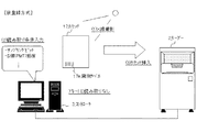
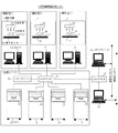
このカセッテタイプの放射線画像診断システムについて、図16を参照して説明する。図16に示すように、従来のカセッテタイプの放射線画像診断システム1は、被検体Mを撮影する放射線撮影装置4が各々設置される複数の撮影室と、放射線エネルギーを蓄積する輝尽性蛍光体シート18を備える放射線画像変換プレートが内蔵された持ち運び可能なカセッテ17から放射線画像を読み取る画像読み取り装置(リーダー2)が集中的に設置される作業スペースとからなり、各々の撮影室にはリーダー2を制御すると共に放射線画像の表示や患者情報、撮影部位情報の入力などを行う制御装置(コントローラー3)が設置され、スイッチングHUB5を介してリーダー2やコントローラー3、ジョブマネージャー19、スタディマネージャー20などがLAN接続されている。
This cassette type radiological image diagnostic system will be described with reference to FIG. As shown in FIG. 16, a conventional cassette-type radiographic image diagnosis system 1 includes a plurality of imaging rooms each provided with a
そして、撮影室内で、放射線源16とカセッテ17の間に被検体Mを位置させ、放射線源16から放射線を照射すると、カセッテ17内の輝尽蛍光体シート18は、照射された放射線エネルギーの一部を蓄積する。撮影後、このカセッテ17を作業スペースに持ち込んでリーダー2にセットすると、リーダー2は、カセッテ17内の輝尽蛍光体シート18に励起光を照射し、照射された励起光により蓄積された放射線画像情報に応じて発光する輝尽光を光電変換し、A/D変換後、デジタル画像データとして出力する。
When the subject M is positioned between the
また、コントローラー3は、リーダー2の読み取り制御を行うと共に、患者情報や撮影部位などの情報を入力したり、読み取った画像を確認するための表示手段を有しており、この表示手段では、例えば、登録した患者の情報が一覧表示される受付リスト画面、新規の患者を登録したり所定の検索条件を入力して患者情報を検索する登録/検索画面、選択した患者に対して撮影部位情報等を設定する撮影部位選択画面、撮影した画像もしくは撮影した画像に画像処理を施した画像を表示する画像表示画面、画像処理に用いる画像処理条件を変更する画像処理調整画面、画像を出力するための出力プロパティ画面等が順次表示され、読み取りから画像の出力までのワークフローを実現する。
Further, the
上記撮影装置4で得られた医用画像はコントローラー3の画面上に表示するのみならず、レーザーイメージャーなどのプリンタでフィルムとして出力する場合も多く、画面上に表示された画像をフィルムとして出力する場合には、画像のサイズ(カセッテ17のサイズ)や画像の読影向き、1枚のフィルムに記録する画像の駒数など、様々な出力条件を設定しなければならない。
The medical image obtained by the
ここで、コントローラー3を操作する専用のオペレータがいる大病院では、プリント出力するための各種条件を設定するのは容易であるが、開業医の場合は、放射線技師や医師の数も少なく、通常、コントローラー3を操作する専用のオペレータもいないため、放射線技師や医師自らがプリント出力するための各種条件の設定をしなければならず面倒であり、画像のサイズや向きにかかわらず特定のサイズ、例えば最大サイズである半切サイズのフィルムに画像を1つずつ出力するのではフィルムの無駄が多くなってしまい経済的ではない。
Here, in a large hospital with a dedicated operator for operating the
また、開業医の場合は、大病院のように撮影作業者が複数の部位や方向の撮影を行うことは希で定型パターンの撮影のみを行う場合がほとんどであることから、プリント出力するための各種条件を自動的に設定することも可能であり、簡単な操作で画像を出力することができるシステムや方法の提案が望まれていた。 In the case of a practitioner, it is rare for a radiographer to take images of multiple parts and directions as in a large hospital, and it is often the case that only a standard pattern is taken. It is also possible to automatically set conditions, and there has been a demand for a system and method that can output an image with a simple operation.
本発明は上記問題点に鑑みてなされたものであり、その主たる目的は、煩雑な出力条件設定を行うことなく、簡単に医用画像を出力することができる画像出力制御方法及び画像出力制御プログラムを提供することにある。特に、発明者等の解析によれば、開業医では、1患者に対する撮影枚数は最大4枚以下が大半を占めており、この実状を加味した出力方法を提供する。 The present invention has been made in view of the above problems, and a main purpose thereof is to provide an image output control method and an image output control program capable of easily outputting a medical image without setting complicated output conditions. It is to provide. In particular, according to the analysis by the inventors, a practitioner occupies most of the maximum number of images taken for one patient by 4 or less, and provides an output method that takes this actual situation into account.
上記目的を達成するため、本発明の画像出力制御方法は、被写体を撮影して得られた放射線画像をフィルムに出力する機能を備えた医用画像システムにおける画像出力制御方法であって、前記放射線画像のサイズ、前記放射線画像の読影向き及び1枚のフィルムに記録する前記放射線画像の駒数を入力パラメータとして、予め定められた手順に従って、1駒又は複数駒の前記放射線画像を記録する前記フィルムのサイズ、前記フィルムの向き及び複数駒の前記放射線画像を記録する場合における前記フィルムの分割方向を自動的に設定するものである。 In order to achieve the above object, an image output control method of the present invention is an image output control method in a medical image system having a function of outputting a radiographic image obtained by photographing a subject to a film, the radiographic image The size of the film for recording the radiographic image of one frame or a plurality of frames according to a predetermined procedure using the size of the radiographic image, the direction of interpretation of the radiographic image and the number of frames of the radiographic image to be recorded on one film as input parameters The direction of the film and the dividing direction of the film when the radiographic images of a plurality of frames are recorded are automatically set.
本発明においては、前記フィルムサイズの設定に際して、1駒の前記放射線画像又は配列された複数駒の前記放射線画像全体の短辺(a)及び長辺(b)を取得する第1のステップと、プリンタに装填されているフィルムの内、最小サイズのフィルムを選択する第2のステップと、選択された前記フィルムの短辺(a’)及び長辺(b’)を取得する第3のステップと、aとa’、bとb’とを各々比較し、a’≧a、かつ、b’≧bの関係を満足するか否かを判定する第4のステップと、前記関係を満足する場合は前記選択されたフィルムを前記1駒又は複数駒の放射線画像を記録するフィルムとして特定し、前記関係を満足しない場合は次に大きいサイズのフィルムを選択して前記第3のステップ以降を実行する第5のステップと、を実行することが好ましく、前記放射線画像が2駒の場合は、該2駒の放射線画像各々の読影方向を維持しながら左右方向に配列した場合と上下方向に配列した場合の双方に対して、前記フィルムの特定を行い、特定された2つのフィルムのサイズが異なる場合は、小さいサイズのフィルムを前記2駒の放射線画像を記録するフィルムとして特定すると共に、前記放射線画像の配列方向に従って前記フィルムの分割方向を設定し、前記放射線画像が4駒の場合は、該4駒の放射線画像各々の読影方向を維持しながら2行2列に配列した画像全体に対して出力するフィルムを特定する構成とすることができる。 In the present invention, when setting the film size, the first step of acquiring the short side (a) and the long side (b) of the entire radiographic image of one frame or the plurality of arranged radiographs, A second step of selecting a minimum size film among the loaded films; a third step of obtaining a short side (a ′) and a long side (b ′) of the selected film; And a ′, b and b ′ are respectively compared, and a fourth step for determining whether or not a relationship of a ′ ≧ a and b ′ ≧ b is satisfied, and if the relationship is satisfied, The selected film is specified as a film for recording the radiation image of one frame or a plurality of frames, and if the relationship is not satisfied, the next largest film is selected and the third and subsequent steps are executed. Step and the real Preferably, when the radiographic image is two frames, the film is specified for both the case where the radiographic images of the two frames are arranged in the horizontal direction and the case where the radiographic images are arranged in the vertical direction while maintaining the interpretation direction. When the two specified films are different in size, the small film is specified as the film for recording the two frames of radiographic images, and the film dividing direction is set according to the arrangement direction of the radiographic images. When the number of the radiographic images is four, the film to be output can be specified for the entire image arranged in two rows and two columns while maintaining the interpretation direction of each of the four radiographic images.
また、本発明においては、前記フィルムの向きの設定に際し、前記特定されたフィルムの中の1駒の前記放射線画像が記録される領域の縦横比と、前記読影向きにおける前記放射線画像の縦横比とを比較し、該縦横比の差を用いてフィルムの向きを設定することが好ましく、前記放射線画像が1駒の場合は、前記特定されたフィルム全体の縦横比と、前記読影向きにおける該1駒の前記放射線画像の縦横比とを比較してフィルムの向きを設定し、前記放射線画像が2駒の場合は、前記特定されたフィルムを縦向きにした場合の1/2の領域の縦横比と、該1/2の領域に記録される前記読影向きにおける1駒の前記放射線画像の縦横比とを比較すると共に、前記特定されたフィルムを横向きにした場合の1/2の領域の縦横比と、該1/2の領域に記録される前記読影向きにおける1駒の前記放射線画像の縦横比とを比較して、該縦横比の差の合計が少ない方をフィルムの向きとして設定し、前記放射線画像が4駒の場合は、前記特定されたフィルムを縦向きにした場合の1/4の領域の縦横比と、該1/4の領域に記録される前記読影向きにおける1駒の前記放射線画像の縦横比とを比較すると共に、前記特定されたフィルムを横向きにした場合の1/4の領域の縦横比と、該1/4の領域に記録される前記読影向きにおける1駒の前記放射線画像の縦横比とを比較して、縦横比の差の合計が少ない方をフィルムの向きとして設定する構成とすることができる。 Further, in the present invention, when setting the orientation of the film, an aspect ratio of an area in which the radiation image of one frame in the specified film is recorded and an aspect ratio of the radiation image in the interpretation direction are determined. In comparison, it is preferable to set the orientation of the film using the difference in aspect ratio. When the radiation image is one frame, the aspect ratio of the entire film specified and the radiation of the frame in the interpretation direction The orientation of the film is set by comparing with the aspect ratio of the image, and when the radiation image is two frames, the aspect ratio of the ½ area when the specified film is oriented vertically, The aspect ratio of the radiation image of one frame in the interpretation direction recorded in the area of 2 is compared, and the aspect ratio of the area of 1/2 when the specified film is turned sideways, of Compared with the aspect ratio of the radiographic image of one frame in the interpretation direction recorded in the area, the direction having the smaller difference of the aspect ratio is set as the film direction, and when the radiographic image is four frames, Comparing the aspect ratio of the 1/4 area when the specified film is oriented vertically with the aspect ratio of the radiographic image of one frame in the interpretation direction recorded in the 1/4 area; The aspect ratio of the ¼ area when the specified film is turned sideways is compared with the aspect ratio of the radiation image of one frame in the interpretation direction recorded in the ¼ area. The direction with the smaller total difference can be set as the film orientation.
また、本発明のプログラムは、被写体を撮影して得られた放射線画像をフィルムに出力する機能を備えた医用画像システムで動作させる画像出力制御プログラムであって、コンピュータを、前記放射線画像のサイズ、前記放射線画像の読影向き及び1枚のフィルムに記録する前記放射線画像の駒数を入力パラメータとして、予め定められた手順に従って、1駒又は複数駒の前記放射線画像を記録する前記フィルムのサイズ、前記フィルムの向き及び複数駒の前記放射線画像を記録する場合における前記フィルムの分割方向を自動的に設定する画像出力制御手段として機能させるものである。 Further, the program of the present invention is an image output control program that is operated by a medical image system having a function of outputting a radiographic image obtained by photographing a subject to a film, the computer having a size of the radiographic image, Using the radiographic image interpretation direction and the number of frames of the radiographic image to be recorded on one film as input parameters, the film size for recording the radiographic image of one frame or a plurality of frames according to a predetermined procedure, the film And an image output control means for automatically setting the film dividing direction when recording the plurality of frames of radiographic images.
このように、本発明によれば、画像出力制御プログラムにより、画像サイズや画像の読影向き、画像の駒数を入力パラメータとして、フィルムサイズやフィルムの向き、フィルムの分割方向が自動的に設定されて出力されるため、ユーザは画像を出力するたびに出力条件を設定する必要がなくなり、特に、開業医のように専用のオペレータがおらず、定型パターンの撮影が多い場合において、作業性を格段に向上させることができる。 Thus, according to the present invention, the image size, film orientation, and film division direction are automatically set by the image output control program using the image size, image interpretation direction, and the number of image frames as input parameters. Therefore, it is not necessary for the user to set output conditions each time an image is output, especially when there is no dedicated operator like a practitioner and there are many routine pattern shootings. Can be improved.
本発明の画像出力制御方法及び画像出力制御プログラムによれば、医用画像をレーザーイメージャーなどのプリンタに出力する際に、画像を出力するたびに出力条件を設定する必要がなくなり、特に、専用のオペレータがおらず、定型パターンの撮影が多い開業医では、作業性を格段に向上させることができる。 According to the image output control method and the image output control program of the present invention, when outputting a medical image to a printer such as a laser imager, it is not necessary to set an output condition every time an image is output. A practitioner who does not have an operator and frequently captures a fixed pattern can significantly improve workability.
その理由は、画像サイズや画像の読影向き、画像の駒数を入力パラメータとして設定すると、予め定められたルールに従って、フィルムサイズやフィルムの向き、フィルムの分割方向が自動的に設定されるからである。 The reason is that when the image size, image interpretation direction, and number of image frames are set as input parameters, the film size, film orientation, and film division direction are automatically set according to predetermined rules. is there.
従来技術で示したように、従来の放射線画像診断システムは、多数の撮影装置4やリーダー2、コントローラー3を備え、多数の放射線技師が撮影装置を操作し、多数の医師が撮影装置4で撮影して得られた放射線画像を用いて診断を行う大病院を対象としており、様々な患者の様々な部位を撮影した医用画像をフィルムに出力できるように、出力プロパティ画面で、オペレータがフィルムサイズやフィルムの向き、フィルムの分割方向などの出力条件を設定する構成としていたが、撮影装置4やリーダー2、コントローラー3の設置台数や放射線技師、医師の数も少なく、特定の部位を定型パターンで撮影する場合が多い開業医では、できるだけ簡単な操作で放射線画像を用いた診断ができるようにシステムを構成することが望まれる。
As shown in the prior art, the conventional radiological image diagnosis system includes a large number of
そこで、本発明では、コントローラーに画像出力制御手段をハードウェア又はソフトウェアとして構成することにより、フィルムサイズやフィルムの向き、フィルムの分割方向などの出力条件を自動的に設定できるようにし、これにより、プリント出力の際の煩雑な作業を簡略化して、特に、開業医のような小規模のユーザの操作性の向上を図っている。 Therefore, in the present invention, by configuring the image output control means as hardware or software in the controller, it is possible to automatically set the output conditions such as the film size, the film orientation, and the film dividing direction. The complicated work at the time of print output is simplified, and in particular, the operability of a small user such as a practitioner is improved.
上記した本発明の一実施の形態について更に詳細に説明すべく、本発明の一実施例に係る画像出力制御方法及び画像出力制御プログラムについて、図1乃至図14を参照して説明する。図1は、本発明の制御装置(コントローラ)を含む放射線画像診断システムの構成を模式的に示す図であり、図2は、画像読み取り装置(リーダー)及びコントローラーの構成を示すブロック図であり、図3は、カセッテの構造を示す斜視図である。また、図4及び図5は画像読み取りにおける撮影条件の登録方式を説明するための図であり、図6乃至図9は、コントローラーで表示される画面の構成例を示す図である。また、図10は、本実施例のコントローラーを用いた処理手順を示すフローチャート図であり、図11及び図13は医用画像の出力手順を示すフローチャート図、図12及び図14は、医用画像の出力手順を模式的に示す図である。 In order to describe the above-described embodiment of the present invention in more detail, an image output control method and an image output control program according to an embodiment of the present invention will be described with reference to FIGS. FIG. 1 is a diagram schematically illustrating a configuration of a radiological image diagnosis system including a control device (controller) according to the present invention. FIG. 2 is a block diagram illustrating configurations of an image reading device (reader) and a controller. FIG. 3 is a perspective view showing the structure of the cassette. 4 and 5 are diagrams for explaining a registration method of photographing conditions in image reading, and FIGS. 6 to 9 are diagrams illustrating configuration examples of screens displayed on the controller. FIG. 10 is a flowchart showing a processing procedure using the controller of this embodiment, FIGS. 11 and 13 are flowcharts showing a procedure for outputting a medical image, and FIGS. 12 and 14 are outputs of a medical image. It is a figure which shows a procedure typically.
なお、以下の説明においては、カセッテタイプの放射線画像診断システム1に本発明を適用する例について記載するが、本発明は以下の実施例に限定されるものではなく、他の放射線画像変換媒体を使用するシステムや放射線画像変換媒体を使用しない立位/臥位専用タイプのシステム、FPD等の放射線ディテクタを用いて放射線画像をデジタル信号として直接取り出すシステム等の医用画像の表示を行う任意の装置に適用することができる。また、本実施例において、リーダー2とコントローラー3とは分離された形態としているが、これらが一体となって制御装置を構成する形態とすることもできる。
In the following description, an example in which the present invention is applied to the cassette-type radiological image diagnostic system 1 will be described. However, the present invention is not limited to the following embodiments, and other radiographic image conversion media are used. For any device that displays a medical image, such as a system that uses it, a stand-up / stand-only system that does not use a radiographic image conversion medium, or a system that directly extracts a radiographic image as a digital signal using a radiation detector such as an FPD Can be applied. Further, in the present embodiment, the
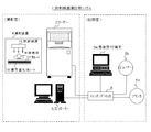
図1に示すように、本実施例の放射線画像診断システム1は、患者を撮影する撮影装置4が設置される撮影室内に、撮影装置4によって潜像が形成されたカセッテ17から放射線画像を読み取るリーダー2と、リーダー2の読み取りを制御すると共に、読み取った画像を表示したり、患者情報や撮影部位情報等を入力する制御装置(コントローラー3)とが設置され、リーダー2及びコントローラー3は、スイッチングHUB5を介して、必要に応じて設置されるプリンタ6c、ビューアー6b、患者受付端末6aなどとLAN接続されている。また、図示していないが、これらの装置はDICOM等のネットワークにより他の医用機器と接続されている。なお、図1は、放射線画像診断システム1の一例であり、リーダー2やコントローラー3、撮影装置4の設置台数や配置などは特に限定されない。
As shown in FIG. 1, the radiological image diagnosis system 1 of this embodiment reads a radiographic image from a
また、図2に示すように、装置4で撮影して得られた画像データの読み取りを行うリーダー2と、リーダー2の読み取り制御、患者情報や撮影部位情報等の入力及び画像データに基づく放射線画像の表示を行うコントローラー3とは、直接接続又はネットワーク経由で接続され、例えば、リーダー2は、例えば、図2に示すように、カセッテ17の投入制御を行うカセッテスタッカ部8と、カセッテ17から抜き出した輝尽蛍光体シート18を含む放射線画像変換プレート(カセッテ17の構造については図3参照)の搬送制御を行うプレート制御部7と、放射線画像変換プレートを走査しながら潜像を読み取る画像読取部9とから構成されている。
As shown in FIG. 2, a
カセッテスタッカ部8には、カセッテスタッカ部機構・駆動部8a及びカセッテスタッカ部制御部8bが設けられ、複数種類のカセッテ17がセット可能になっている。また、プレート制御部7には、プレート搬送部機構・駆動部7a及びプレート搬送部制御部7bが設けられ、カセッテスタッカ部制御部8bからの指令に基づき、プレート搬送部制御部7bが制御される。プレート搬送部機構・駆動部7aは、カセッテ17から放射線画像変換プレートを引き出し、画像読取部9方向に搬送する。画像読取部9には、副走査部機構・駆動部9a、主走査部9b及び識別ラベル検出部9cが設けられ、副走査部機構・駆動部9aにより主走査部9bが副走査方向に搬送され、主走査部9bのレーザ走査により画像読み取りが行われると共に、識別ラベル検出部9cによりカセッテ17に貼付された識別ラベルの情報(プレートID)が読み取られる。
The cassette stacker unit 8 is provided with a cassette stacker unit mechanism / drive unit 8a and a cassette stacker unit control unit 8b, and a plurality of types of
また、リーダー2の読み取り制御、患者情報や撮影部位情報等の入力及び画像データに基づく放射線画像の表示を行うコントローラー3は、設定した読み取り条件に基づいてリーダー2を制御する制御部10と、リーダー2で読み取った画像に対して種々の画像処理(階調変換処理、周波数処理、トリミング、反転/回転、マスキング等)を施す演算処理部11と、表示・操作部12と、レーザーイメージャーなどのプリンタへ出力する際の各出力条件を自動的に設定する画像出力制御部13と、表示用の画像データや、各撮影部位の撮影条件パラメータ、各特定部位を最適に画像処理するための画像処理パラメータ及び出力フォーマット等を記憶する記憶部14と、カセッテ17のプレートIDを読み取る識別ラベル検出部15とを備えている。なお、上記各手段はコントローラー3にハードウェアとして構成されていてもよいが、コンピュータを少なくとも画像出力制御部13として機能させる画像出力制御プログラムとして構成し、該画像出力制御プログラムをコントローラー3にインストールして実行させる構成としてもよい。
In addition, the
この画像出力制御部13では、後述するように、画像サイズ(カセッテ17のサイズ)、画像読影向き、1枚のフィルムに記録する画像の駒数を入力パラメータとして、出力するフィルムのサイズ、フィルムの向き、フィルムの分割方向を自動的に設定して画像出力の制御を行う。
As will be described later, the image
また、上記記憶部14に記憶される撮影条件パラメータは、各撮影部位に対応したパラメータセットであり、リーダー2で画像を読み取る際の読み取り条件(サンプリングピッチや読み取り感度等)や、読み取り後の画像の画像処理時に参照される画像処理パラメータの識別番号が、撮影部位毎に保持されている。
The imaging condition parameters stored in the
この画像処理パラメータは、ある特定部位を最適に画像処理するためのパラメータセットであり、階調変換処理の階調曲線を定義したルックアップ・テーブルや、周波数処理の強調度といった各画像処理のパラメータ値が特定部位毎に保持されている。また、出力フォーマットは、レーザーイメージャーなどのプリンタ6cへ出力する場合に、1枚のフィルム上にいくつの画像データを配置するか、各画像データをどのような向きで配置するかを定義したフォーマットであり、オペレータが表示・操作部12で選択した出力フォーマットに1乃至複数の画像データがはめ込まれ、各画像データ及びフォーマット情報等の付帯情報がDICOM対応プリンタ6cへ出力される。
This image processing parameter is a parameter set for optimal image processing of a specific part. Each image processing parameter such as a look-up table that defines a gradation curve for gradation conversion processing and frequency processing enhancement degree is used. A value is held for each specific part. The output format is a format that defines how many image data are arranged on one film and in what direction each image data is arranged when outputting to a printer 6c such as a laser imager. One or a plurality of image data is inserted into the output format selected by the operator using the display /
上記カセッテタイプの放射線画像診断システム1では、撮影部位情報とカセッテ17の対応関係を明確にするために、予め撮影部位情報とカセッテ17との対応付けを撮影予約情報として登録した後に撮影を行う方法(前登録)や、放射線撮影前にカセッテ17の登録を行うことなく、撮影部位情報とカセッテ投入順序との対応付けを撮影予約情報として登録する方法(後登録)のいずれかが採用されて、画像データの読み取りが実行される。
In the cassette type radiological image diagnosis system 1, in order to clarify the correspondence between the imaging region information and the
また、撮影部位情報の入力では、通常モードと、繰り返しモードの2種類のモードが存在し、このうちのいずれかが採用される。通常モードは、コントローラー3の表示・操作部12にて、撮影部位情報を入力するたびに、逐次、当該撮影部位における撮影を予約していくモードである。一方、繰り返しモードは、コントローラー3の表示・操作部12にて一旦選択された撮影部位情報が、以降の読み取り動作における撮影部位情報の設定値として保持されるモードであり、同じ撮影部位の画像データを連続して読み取る場合には撮影部位情報の入力の手間が省ける。
In addition, there are two types of modes, ie, a normal mode and a repeat mode, for inputting the imaging part information, and any one of these modes is adopted. The normal mode is a mode in which imaging at the imaging region is sequentially reserved every time imaging region information is input on the display /
まず、通常モードの前登録方式、後登録方式の動作について図4及び図5を参照して説明する。 First, operations of the normal mode pre-registration method and post-registration method will be described with reference to FIGS.
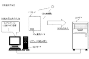
前登録方式の場合は、図4に示すように、まず、オペレータはコントローラー3の表示・操作部12により、撮影部位情報を入力する(図の(1))。その際、コントローラー3の識別ラベル検出部15によりカセッテ17に貼り付けられた識別ラベル17e(図3参照)の情報(以下、プレートIDと称する。)を読み取る(図の(2))。そして、入力した撮影部位情報とプレートIDとを対応付けて記憶する。その後、登録したカセッテ17を用いてX線撮影を行い(図の(3))、潜像を形成したカセッテ17をリーダー2に挿入する(図の(4))。リーダー2では、内蔵する識別ラベル検出部9cによりカセッテ17のプレートIDを読み取り、このプレートIDに対応する撮影部位情報を検索して取得する。また、当該撮影部位情報に対応する撮影条件パラメータのセットを読み出し、該パラメータセットからリーダー2で画像を読み取る際の読み取り条件を取得する。そして、取得した読み取り条件にて画像の読み取りを実行する。読み取られた画像データはコントローラーに送信され、コントローラーでは、撮影条件パラメータのセットから、画像処理パラメータの識別番号が取得され、該画像処理パラメータに基づいた画像処理条件に従い、読み取った画像に画像処理が施される。
In the case of the pre-registration method, as shown in FIG. 4, first, the operator inputs imaging part information through the display /
一方、後登録方式の場合は、図5に示すように、放射線技師等のオペレータは最初にX線撮影を行い(図の(1))、その後、コントローラー3の表示・操作部12により撮影部位情報を入力する(図の(2))。ここで、後登録方式の場合はプレートIDと撮影部位情報との対応付けは行わないため、プレートIDの読み取りを行う必要はない。その代わりに、オペレータは、コントローラー3の表示・操作部12により、入力した各撮影部位情報と、リーダー2におけるカセッテ17の投入順序との対応付けを行い、入力した撮影部位情報と投入順序とを対応付けて記憶させる。潜像を形成したカセッテ17をリーダー2に挿入すると(図の(3))、リーダー2では、投入順序に対応する撮影部位情報を検索して取得し、当該撮影部位情報に対応する撮影条件パラメータセットを読み出し、該パラメータセットから読み取り条件を取得し、該読み取り条件にて画像の読み取りを実行する。以降は前登録と同様に、読み取られた画像データはコントローラーに送信され、コントローラーでは、撮影条件パラメータのセットから、画像処理パラメータの識別番号が取得され、該画像処理パラメータに基づいた画像処理条件に従い、読み取った画像に画像処理が施される。
On the other hand, in the case of the post-registration method, as shown in FIG. 5, an operator such as a radiographer first performs X-ray imaging ((1) in the figure), and then the imaging region is displayed by the display /
次に、繰り返しモードでの前登録方式、後登録方式の動作について説明する。 Next, operations of the pre-registration method and the post-registration method in the repetition mode will be described.
前登録方式の場合は、まず、オペレータが、コントローラー3の表示・操作部12にて、ある撮影部位情報を選択する。以降、プレートIDが読み取られるたびに、選択されている撮影部位情報と、プレートIDとを対応づけて撮影予約情報として記憶する。これ以降の動作は、通常モードでの前登録方式の動作と同様である。
In the case of the pre-registration method, first, the operator selects certain imaging region information on the display /
後登録方式の場合は、まず、オペレータが、コントローラー3の表示・操作部12にて、ある撮影部位情報を選択する。以降、カセッテ17がリーダー2に投入されるたびに、選択された撮影部位情報の撮影条件パラメータを読み出し、該パラメータセットから読み取り条件を取得して画像を読み取る。以降は前述の通り、読み取られた画像データはコントローラーに送信され、コントローラーでは撮影条件パラメータのセットから画像処理パラメータの識別番号が取得され、該画像処理パラメータに基づいた画像処理条件に従い、読み取った画像に画像処理が施される。
In the case of the post-registration method, first, the operator selects certain imaging region information on the display /
前登録方式と後登録方式では各々特徴があり、例えば、リーダー2やコントローラー3が各々異なる場所に多数設置され、多数の放射線技師が撮影を行う病院等では、前登録によって多数の患者の放射線画像診断を的確に行うことができ、一方、リーダー2やコントローラー3の設置台数の少なく、少数の放射線技師が撮影を行う開業医等では、後登録によって迅速かつ効率的にX線撮影を行うことができる。なお、本実施例の特徴である画像処理方法は、いずれの登録方式を採用する場合においても適用可能である。また、通常モード、繰り返しモードの設定、及び、前登録、後登録の設定は、図示しない画面にて設定の変更が行えるようになっており、この画面上で設定を変更しない限り、常に前の設定が保持されるようになっている。
Each of the pre-registration method and the post-registration method has its own characteristics. For example, in a hospital where a number of
次に、上記構成の放射線画像診断システム1を用いて、患者のX線画像を撮影してからレーザーイメージャーなどのプリンタ、もしくは、患者の受付を行うホスト端末に出力するまでの手順について、図6乃至図9の画面構成例、図10乃至図12のフローチャート図、図13乃至図15の模式図を参照して説明する。なお、以下の説明では通常モードの前登録方式で画像データの読み取りを行う場合の手順について記載するが、後登録方式であっても、繰り返しモードであっても、画像データの読み取り以降の動作は同様である。また、以下では、特に開業医のような小規模のユーザに適した画面(画像確認/出力画面21)が表示される場合について示すが、画面の構成は任意であり、受付リスト画面や登録/検索画面、撮影部位選択画面、画像表示画面、画像処理調整画面、出力プロパティ画面等が順次表示される構成においても、本発明の画像出力制御方法を同様に適用することができる。 Next, a procedure from taking an X-ray image of a patient using the radiation image diagnostic system 1 having the above-described configuration to outputting the image to a printer such as a laser imager or a host terminal that accepts a patient is illustrated in FIG. Description will be made with reference to screen configuration examples in FIGS. 6 to 9, flowcharts in FIGS. 10 to 12, and schematic diagrams in FIGS. In the following description, the procedure for reading image data in the pre-registration method in the normal mode is described. However, the operation after reading the image data is the same in the post-registration method and the repeat mode. It is the same. Further, in the following, a case where a screen (image confirmation / output screen 21) suitable for a small user such as a medical practitioner is displayed will be described. However, the configuration of the screen is arbitrary, such as a reception list screen or registration / search The image output control method of the present invention can be similarly applied to a configuration in which a screen, an imaging region selection screen, an image display screen, an image processing adjustment screen, an output property screen, and the like are sequentially displayed.
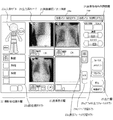
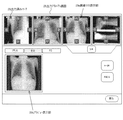
まず、コントローラー3の表示・操作部12には、初期画面として、図示しない患者情報入力画面が表示されており、ステップS101で、被検体となる患者の情報を入力する。すると、ステップS102で、コントローラー3の表示・操作部12には、例えば、図6に示すような撮影部位選択欄22と画像表示欄23と画像処理条件調整欄24とを含む画像確認/出力画面21が表示される。ここで、ネットワークに接続されている患者データベース、検査データベースから患者情報を受信する場合は、患者情報入力画面を表示せず、画像確認/出力画面21を初期画面とすることもでき、この初期画面は、図示しない設定画面にて設定される。
First, a patient information input screen (not shown) is displayed on the display /
次に、ステップS103で、オペレータにより撮影部位情報を入力するが、開業医のような小規模なユーザの場合は撮影部位選択画面や画像表示画面、画像調整画面などが複雑に遷移すると操作が複雑になる。そのため、ここでは図11に示すような画像確認/出力画面21を用いて、撮影部位情報を入力する構成としている。この画像確認/出力画面21では、開業医のような小規模なユーザの場合は撮影する部位や撮影方向が限られていることから、撮影部位選択欄22には、所定の領域毎(例えば、頭部、頚部、胸部、腹部、骨盤、四肢、特殊部位)に選択可能に分割された人体の模式図(人体モデル22a)を含む第1の選択欄と、人体モデル22aの中から選択された領域に包含される部位(例えば、頭部の場合は頭部概観、頬骨、顎骨、鼻骨、聴器、顎関節、頚部の場合は頸椎、咽頭/喉頭、胸部の場合は胸部、胸椎、胸骨、腹部の場合は腹部、胸腰椎、腰椎、肋骨、骨盤の場合は骨盤/股関節、四肢骨一般、アキレス腱、踵軸位、種子骨、特殊部位の場合は腹部KUB/DIP、DIC/膀胱造影、新生児胸腹、新生児骨部、セファロ、パントモグラフィ、耳下腺顎下腺、長尺全脊椎、長尺下肢など)が選択可能に表示される部位選択ボタン22bを含む第2の選択欄とを設け、所望の部位を容易に選択できるようにしている。 Next, in step S103, the imaging part information is input by the operator. However, in the case of a small user such as a medical practitioner, the operation becomes complicated when the imaging part selection screen, the image display screen, the image adjustment screen, and the like transition in a complicated manner. Become. For this reason, here, the imaging region information is input using an image confirmation / output screen 21 as shown in FIG. In the image confirmation / output screen 21, in the case of a small-scale user such as a medical practitioner, the region to be imaged and the imaging direction are limited. A first selection field including a schematic diagram (human body model 22a) of the human body divided in a selectable manner into a head, a neck, a chest, an abdomen, a pelvis, extremities, and a special part, and an area selected from the human body model 22a (E.g. head overview for head, cheekbone, jawbone, nasal bone, hearing aid, temporomandibular joint, cervical vertebrae for cervix, pharynx / larynx, chest for chest, thoracic vertebrae, sternum, abdomen) In the case of abdomen, thoracolumbar vertebrae, lumbar vertebrae, ribs, in the case of pelvis, pelvis / hip joint, limb bones in general, Achilles tendon, heel axis position, seed bone, in the case of special part, abdominal KUB / DIP, DIC / cystography, neonatal thoracoabdominal , Newborn bone, cephalo, pantomograph , Parotid submandibular gland, long whole spine, long leg, etc.) and a second selection field including a part selection button 22b that can be displayed so that a desired part can be easily selected. ing.
より具体的には、オペレータが人体モデル22aの特定箇所(例えば、胸部)を選択すると、選択した箇所周辺の詳細な撮影部位(例えば、胸部、胸椎、胸骨など)が、選択可能な撮影部位の一覧として部位選択ボタン22bに表示される。そして、オペレータはこの中から詳細な撮影部位を選択することによって、撮影部位情報を入力する。 More specifically, when the operator selects a specific part (for example, the chest) of the human body model 22a, detailed imaging parts (for example, the chest, thoracic vertebra, and sternum) around the selected part are selectable imaging parts. The list is displayed on the part selection button 22b. And an operator inputs imaging | photography site | part information by selecting a detailed imaging | photography site | part from this.
次に、ステップS104で、オペレータは、コントローラー3の識別ラベル検出部15を用いて、カセッテ17に貼り付けられた識別ラベル17eの情報を読み取り、識別ラベル情報(プレートID)と撮影部位情報とを対応付けて記憶させる。
Next, in step S104, the operator uses the identification
次に、ステップS105で、公知の方法により、X線撮影装置等の撮影装置4を用いて選択した患者を撮影し、患者のX線透過画像をカセッテ17内部の放射線画像変換プレートに潜像として記録させる。なお、撮影装置4としてはX線撮影装置に限らず、磁気や超音波を用いて患者を撮影する装置等、医療現場で使用される任意の撮影装置が含まれる。
Next, in step S105, the selected patient is imaged by a known method using the
次に、放射線技師等のオペレータは撮影装置4からカセッテ17を取り出し、取り出したカセッテ17をリーダー2の任意のスロットに挿入する。すると、前登録の場合は、リーダー2は、識別ラベル検出部9cによりプレートIDを読み取り、プレートIDを検索キーとして撮影予約情報が記憶されたデータベースを検索し、プレートIDに対応する撮影部位情報を抽出する。また、後登録の場合は、カセッテ投入順キューと予約撮影部位キューとの対応付けから当該投入順序に対応する撮影部位情報を抽出する。その後、ステップS106で、リーダー2では撮影部位情報に対応付けられた撮影条件パラメータを読み出し、さらにその中から読み取り条件を抽出して、該読み取り条件に従って放射線画像変換プレートの潜像を読み取る。
Next, an operator such as a radiologist takes out the
画像データの読み取り手順としては、まず、読み取り感度の値に従って、画像読取部9の感度が設定され、読み取り解像度の値に従って、プレート搬送部機構駆動部7aの搬送速度や画像読取部9に設けたA/D変換器のサンプリングピッチが設定される。そして、カセッテ17から放射線画像変換プレートが引き出され、副走査部機構駆動部9aで放射線画像変換プレートをXの方向に副走査搬送しながら、放射線画像変換プレートに蓄積・保持された画像データを読み出す。
As the image data reading procedure, first, the sensitivity of the image reading unit 9 is set according to the value of the reading sensitivity, and the conveying speed of the plate conveying unit mechanism driving unit 7a and the image reading unit 9 are provided according to the value of the reading resolution. The sampling pitch of the A / D converter is set. Then, the radiation image conversion plate is pulled out from the
そして、放射線画像変換プレートに励起光が作用すると、蛍光体内部に蓄積されていたエネルギーが輝尽光として発生し、この輝尽光を集光して画像読取部9によって電気信号に変換し、この電気信号を対数変換器にて対数変換し(これによって、電気信号は輝尽光の光強度にリニアな電気信号から、輝尽光の光強度の対数リニアな電気信号、すなわち濃度にリニアな電気信号に変換される。)、さらにA/D変換器によってデジタル化する。 Then, when excitation light acts on the radiation image conversion plate, the energy accumulated in the phosphor is generated as stimulating light, and the stimulating light is collected and converted into an electrical signal by the image reading unit 9, This electric signal is logarithmically converted by a logarithmic converter (the electric signal is changed from an electric signal linear to the light intensity of the stimulating light to a logarithmic linear electric signal of the light intensity of the stimulating light, that is, linear to the concentration. It is converted into an electrical signal.) Further, it is digitized by an A / D converter.
画像読取部9から出力されるデジタル化された画像データは、その読み取り過程において、随時、画像確認/出力画面21の画像表示欄23に表示される。 The digitized image data output from the image reading unit 9 is displayed in the image display field 23 of the image confirmation / output screen 21 as needed during the reading process.
その後、撮影部位情報に対応した撮影条件パラメータを読み出し、その中に保持される画像処理パラメータ識別番号を取得する。次に、該識別番号により特定された画像処理パラメータのセットを読み出し、該画像処理パラメータに基づき、画像処理条件を決定する。このとき、各画像に対応する該画像処理パラメータの識別番号を、画像毎に記憶部に保持する。決定した画像処理条件に従い、読み取られた画像データに、階調変換処理、周波数処理等の画像処理が施される(ステップS107)。画像処理終了後、前述の読み取り過程において、画像確認/出力画面21の画像表示欄23に表示されていた画像処理前の画像データは、画像処理後の画像データへと置き換えられて表示される(ステップS108)。 Thereafter, the imaging condition parameter corresponding to the imaging region information is read, and the image processing parameter identification number held therein is acquired. Next, a set of image processing parameters specified by the identification number is read, and image processing conditions are determined based on the image processing parameters. At this time, the identification number of the image processing parameter corresponding to each image is stored in the storage unit for each image. In accordance with the determined image processing conditions, the read image data is subjected to image processing such as gradation conversion processing and frequency processing (step S107). After the image processing is completed, the image data before the image processing displayed in the image display field 23 of the image confirmation / output screen 21 in the above-described reading process is replaced with the image data after the image processing and displayed ( Step S108).
ここで、プレートから読み取られた画像を、部位を選択する画面と別個の画面に表示すると、選択した部位と画像との対比が困難であり、部位選択画面と画像表示画面とをその都度遷移させなければならないため操作が煩雑になるため、ここでは画像確認/出力画面21に撮影部位選択欄22に加えて撮影して得られた画像が表示される画像表示欄23を設け、部位と画像との対比を容易にしている。 Here, if the image read from the plate is displayed on a screen separate from the screen for selecting the part, it is difficult to compare the selected part and the image, and the part selection screen and the image display screen are changed each time. In this case, the image confirmation / output screen 21 is provided with an image display field 23 in which an image obtained by photographing is displayed in addition to the photographing part selection field 22, and the part and image are displayed. It is easy to compare.
また、画像表示欄23の各画像の近傍には、部位選択ボタン22bを構成する模式図及び文字が表示されるため、各画像と選択した撮影部位とが簡単に対比できるようになっている。また、この画像周辺に表示された撮影部位情報を選択した後、人体モデル22a及び部位選択ボタン22bにて撮影部位情報を入力することにより、読み取り時の画像処理と同様に撮影条件パラメータの読み出しが行われ、入力した撮影部位情報に基づいて画像処理を再度施すことができる。 Further, a schematic diagram and characters constituting the part selection button 22b are displayed in the vicinity of each image in the image display field 23, so that each image can be easily compared with the selected imaging part. Further, after selecting the imaging part information displayed around the image, the imaging part parameter is input by the human body model 22a and the part selection button 22b, so that the imaging condition parameters can be read out in the same manner as the image processing at the time of reading. The image processing can be performed again based on the inputted imaging region information.
また、この画像表示欄23は、表示フォーマット切替ボタン23aにより、1画像のみを大きく表示する1画像表示か、1画像表示の領域を4分割して画像を並列表示する4画像表示かを切り替えることができるようになっている。また、複数の読み取った画像データが記憶部14に記憶されている場合には、ページ切替ボタン23bにより、画像表示欄23に表示された画像を切り替えることが可能であり、ページ切替ボタン23bを押下すると、1画像表示の場合は1画像ずつ、4画像表示の場合は4画像ずつ、記憶部14に記憶された前後の画像を切り替えて表示する。また、各画像は、入力操作によって選択/非選択のいずれかの状態に切り替えることが可能であり、選択状態に設定された画像には、画像表示欄にて画像を囲む枠線が表示され、選択/非選択の状態は画像毎に記憶される。なお、画像表示欄23に表示された各画像領域を選択指示することで、各画像の選択/非選択の状態を切り替えられるようにしてもよいし、又、画面中に複数画像選択状態切替ボタンを設け、該ボタンが押下される毎に一画像選択状態、複数画像選択状態の切替及び記憶をできるようにし、複数画像選択状態の場合は、前述の通り画像表示欄23に表示された各画像領域を選択指示することで各画像の選択/非選択の状態を切り替えられ、一画像選択状態の場合は、画像表示欄23に表示された各画像領域を選択指示することで、当該選択指示された画像のみが選択状態となるようにしても良い。
The image display field 23 is switched by a display format switching button 23a between one image display for displaying only one image in a large size or four image display for displaying an image in parallel by dividing the area of the one image display into four. Can be done. In addition, when a plurality of read image data is stored in the
次に、ステップS109で、画像表示欄23に表示された画像がオペレータにとって所望の画像でない場合には、オペレータは、画像処理条件調整欄24にて画像処理条件を微調整する。その際、表示された画像に対する画像処理条件を調整する場合に一旦画像処理条件調整用の画面に遷移し、この画像処理条件調整画面で画像処理の条件を調整する構成では操作が煩雑であると共に、複数の画像を見比べながら画像処理の条件を調整することができず不便であることから、ここでは画像確認/出力画面21に更に画像処理条件調整欄23を設け、画像の濃度やコントラストなどをボタンやスライドバーなどによって調整可能に構成し、操作性を向上させている。なお、ここでは階調処理をとりあげ、調整可能な画像処理の例として濃度(最高濃度)とコントラスト(γカーブ)のパラメータ変更例を示しているが、これらに代えて又はこれらと共に、他の処理に係わるパラメータ調整、例えば、周波数処理における強調度等を調整可能としてもよい。また、図では画像確認/出力画面21の右上に画像処理条件調整欄24を設けているが、画像処理条件調整欄24の構成や配置は任意であり、例えば、画像表示欄23に画像が表示された後は画像処理条件調整欄24と撮影部位選択欄22の位置を変えるなど、使用状況に合わせて各々の欄のレイアウトを変更してもよい。 Next, if the image displayed in the image display field 23 is not a desired image for the operator in step S109, the operator finely adjusts the image processing condition in the image processing condition adjustment field 24. At that time, when adjusting the image processing conditions for the displayed image, the screen is temporarily shifted to the image processing condition adjustment screen, and the configuration for adjusting the image processing conditions on the image processing condition adjustment screen is complicated and the operation is complicated. Since it is inconvenient that the image processing conditions cannot be adjusted while comparing a plurality of images, an image processing condition adjustment field 23 is further provided on the image confirmation / output screen 21 to adjust the image density and contrast. It is configured to be adjustable with buttons and slide bars, improving operability. Here, gradation processing is taken up, and examples of changing the density (maximum density) and contrast (γ curve) parameters are shown as examples of image processing that can be adjusted. It may be possible to adjust the parameter adjustment related to the above, for example, the enhancement degree in frequency processing. In the figure, an image processing condition adjustment field 24 is provided in the upper right of the image confirmation / output screen 21. However, the configuration and arrangement of the image processing condition adjustment field 24 are arbitrary. For example, an image is displayed in the image display field 23. Thereafter, the layout of each field may be changed according to the use situation, such as changing the positions of the image processing condition adjustment field 24 and the imaging region selection field 22.
このように調整後の画像処理条件に従って画像処理された画像データが即座に画像表示欄23に表示されるため、オペレータは画像処理条件調整欄24での調整操作を繰り返すことによって画像を確認しながら所望の画像を得ることができる(ステップS110、ステップS111)。 Since the image data processed in accordance with the image processing conditions after adjustment is immediately displayed in the image display field 23, the operator confirms the image by repeating the adjustment operation in the image processing condition adjustment field 24. A desired image can be obtained (step S110, step S111).
なお、この画像処理条件の調整は、複数の画像に対して同時に調整を行うことが可能である。この場合、複数の画像を選択状態とし、前記画像処理条件調整部にて調整操作を行うことで、選択状態に設定された画像の画像処理条件には全て同じ変動量が加算され、変更後の画像処理条件で画像処理した画像が、画像表示欄23に表示される。また、ある一つの画像が選択された状態で、処理パラメータ設定ボタンが押下されると、該選択された画像の画像処理時に使用された画像処理パラメータに更新(上書き)される。 The image processing condition can be adjusted simultaneously for a plurality of images. In this case, by setting a plurality of images in the selected state and performing an adjustment operation in the image processing condition adjusting unit, the same variation amount is added to all the image processing conditions of the image set in the selected state, and the changed An image subjected to image processing under the image processing conditions is displayed in the image display field 23. In addition, when a processing parameter setting button is pressed while a certain image is selected, the image processing parameter used for image processing of the selected image is updated (overwritten).
より具体的には、画像毎に直近の画像処理で使用した画像処理条件が記憶部に保持されており、処理パラメータ設定ボタン24aが押下されると、まず、記憶部14に保持された画像処理条件を読み出し、該画像処理条件基づいて、該画像処理条件を決定するような画像処理パラメータの値を逆算する。次に、当該画像の画像処理時に参照された画像処理パラメータの識別番号を、記憶部から取得する。そして記憶部に記憶された該識別番号を持つ画像処理パラメータを、該画像処理条件から逆算される画像処理パラメータ値にて、上書きし、記憶する。
More specifically, the image processing conditions used in the most recent image processing for each image are held in the storage unit. When the processing
また、ある一つの画像が選択された状態で、処理パラメータ初期化ボタン24bが押下されると、該選択された画像の画像処理時に参照された画像処理パラメータを、メーカー出荷時の初期設定に変更する。具体的には、各々の撮影部位に対応した各画像処理パラメータセットに対し、メーカー初期設定のパラメータ値と、画像処理時に参照されるパラメータ値が記憶部14にそれぞれ記憶されている。メーカー出荷時には、画像処理時に参照されるパラメータ値として、メーカー初期設定のパラメータ値が設定されている。処理パラメータ初期化ボタン24bが押下されると、記憶部から当該画像の画像処理時に参照された画像処理パラメータの識別番号を取得する。該識別番号を持つ画像処理パラメータセットに対するメーカー初期設定のパラメータ値を記憶手段から読み出し、記憶部14に記憶された画像処理時に参照されるパラメータ値を、該メーカー初期設定のパラメータ値で上書きして記憶する。
In addition, when the processing
また、この他、処理パラメータアンドゥボタンを設けると共に、各撮影部位に対応する画像処理パラメータセット毎に直近の更新前の画像処理パラメータ値を記憶部14に記憶させるようにし、前記処理パラメータ設定ボタン24aが押下されたときに更新前の画像処理パラメータ値を記憶し、前記処理パラメータアンドゥボタンが押下されたときに、画像処理時に参照される画像処理パラメータを、該更新前の画像処理パラメータ値に上書きして記憶しても良い。
In addition, a processing parameter undo button is provided, and the latest image processing parameter value before update is stored in the
そして、所望の画像が得られたなら各画像の周辺に設けられたOKボタンを選択し、読み取った画像が意図したものでなければ場合は、NGボタンを押下する。NGボタンが押下されると、画像表示欄23から当該画像データの表示は消され、記憶部14から当該画像データが削除される。また、OKボタンが押下されると、該画像データは画像が確認されたとして、画像データ周辺にOKという印が付与され、これまで表示されていた画像データ周辺のOKボタン、NGボタンを非表示とする。
If a desired image is obtained, an OK button provided around each image is selected. If the read image is not intended, the NG button is pressed. When the NG button is pressed, the display of the image data is erased from the image display field 23 and the image data is deleted from the
次に、所望の画像が得られたら、ステップS112で、該画像をレーザーイメージャーなどのプリンタに出力するための出力条件の設定を行う。この出力条件としては、フィルムサイズ、フィルムの向き、1枚のフィルムにおける複数の画像の配置を特定する出力フォーマットなどがあり、ユーザはこれらの出力条件を後述する出力プロパティ画面で設定することもできるが、開業医のように、医用画像をプリント出力するための専用のオペレータがいない場合には、放射線技師や医師自らが出力の度に上記出力条件を設定しなければならず面倒である。そこで、本実施例では、出力条件をマニュアルで設定するか、自動的に設定するかを選択できるようにしている。以下、その具体的方法について説明する。 Next, when a desired image is obtained, an output condition for outputting the image to a printer such as a laser imager is set in step S112. The output conditions include film size, film orientation, an output format for specifying the arrangement of a plurality of images on one film, and the user can set these output conditions on an output property screen described later. However, when there is no dedicated operator for printing out a medical image like a medical practitioner, the radiologist or the doctor himself / herself has to set the output conditions for each output, which is troublesome. Therefore, in this embodiment, it is possible to select whether the output condition is set manually or automatically. The specific method will be described below.
まず、出力条件をマニュアルで設定する場合は、画像確認/出力画面21の出力欄25に予め設けられているデフォルト出力フォーマットボタン25aとプロパティボタンを用いて設定する。このデフォルト出力フォーマットボタン25aはデフォルトでレーザーイメージャーなどのプリンタに出力する際の、出力フォーマットを選択するボタンである。このデフォルト出力フォーマットボタン25aが押下されるたびに、デフォルトで出力するフォーマットの設定があらかじめ規定したいくつかのフォーマットの中で巡回しながら順次切り替わるようになっており、常に、いずれか一つのフォーマットが選択状態として保持され、選択されているフォーマット名がボタン上に表示される。 First, when the output condition is set manually, it is set using a default output format button 25a and a property button provided in advance in the output field 25 of the image confirmation / output screen 21. The default output format button 25a is a button for selecting an output format when outputting to a printer such as a laser imager by default. Each time the default output format button 25a is pressed, the setting of the format to be output as a default is sequentially switched while circulating among several predetermined formats, and any one format is always selected. The selected format name is held on the button.
具体的には、本実施例では、1枚のフィルムに複数の画像を配置して出力するフォーマットのパターンとして、”A”、”AA”、”A/A”、”AB”、”A/B”、”AB/CD”の計6つのフォーマットを持ち、各々、”A”は1画像で出力、”AA”は1つの画像に対して異なる画像処理を施した2つの画像を横方向に並列に並べて出力、”A/A”は1つの画像に対して異なる画像処理を施した2つの画像を縦方向に並列に並べて出力、”AB”は異なる2つの画像を横方向に並列に並べて出力、”A/B”は異なる2つの画像を縦方向に並列に並べて出力、”AB/CD”は異なる4つの画像を縦2列横2列に並べて出力するフォーマットである。したがって、フォーマット”A”、”AA”、”A/A”は1つの画像データを必要とし、フォーマット”AB”、”A/B”は2つの画像を必要とし、フォーマット”S”は4つの画像データを必要とする。 Specifically, in this embodiment, “A”, “AA”, “A / A”, “AB”, “A /” are used as a pattern of a format in which a plurality of images are arranged and output on one film. B ”and“ AB / CD ”have a total of six formats.“ A ”is output as one image,“ AA ”is two images obtained by performing different image processing on one image in the horizontal direction. “A / A” outputs two images obtained by performing different image processing on one image, arranged in parallel in the vertical direction, and “AB” arranges two different images in parallel in the horizontal direction. Output, “A / B” is a format in which two different images are arranged in parallel in the vertical direction for output, and “AB / CD” is a format in which four different images are arranged in two columns in vertical rows and in two rows for output. Therefore, the formats “A”, “AA”, and “A / A” require one image data, the formats “AB” and “A / B” require two images, and the format “S” has four Requires image data.
また、出力するフィルムのサイズ及び向きを設定する場合は、出力欄25のプロパティボタンを押下して図8又は図9に示すような出力プロパティ画面を表示させて、該出力プロパティ画面上で設定する。 Also, when setting the size and orientation of the film to be output, the property button in the output field 25 is pressed to display the output property screen as shown in FIG. 8 or FIG. 9 and set on the output property screen. .
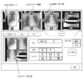
図8は出力先としてプリンタを選択した場合、図9は出力先としてホストを選択した場合の出力プロパティ画面の構成例である。出力先としてプリンタを選択した場合、図8に示すように、オペレータは、出力プロパティ画面27のサイズ選択ボタンからフィルムサイズを選択し、次に、フィルムを縦置きにするか、横置きにするかをフィルム方向選択ボタンにより指定する。次に、出力するフォーマットをフォーマット選択ボタンにより選択する。すると、プレビュー表示部27bに、1フィルム内の画像データの配置が表示される。この表示は1画像データに相当する領域サイズの区画で区切られている。
FIG. 8 shows an example of the configuration of the output property screen when a printer is selected as the output destination, and FIG. 9 shows a configuration example of the output property screen when the host is selected as the output destination. When the printer is selected as the output destination, as shown in FIG. 8, the operator selects the film size from the size selection button on the
この出力プロパティ画面27上部には、これまでに読み取った画像データが表示される画像リスト表示部27aがある。この画像リスト表示部27aからある一つの画像を選択し、その後プレビュー表示部27bのある1画像データの区画を選択すると、当該フォーマットの選択した区画位置に、画像データが配置される。
At the top of the
また、切り出しサイズ選択ボタンにより、当該フォーマットへ画像データを配置する際の切り出しサイズを変更することが可能である。全体ボタンを押下すると、出力フォーマット内に配置される各画像データは、画像全体が表示されるように、出力フォーマット内の一画像に対応する領域サイズに縮小表示される。等倍ボタンを選択すると画像データの縮尺は変更されず、出力フォーマット内の対応する領域サイズのデータが、画像データから切り出される。 In addition, the cutout size when the image data is arranged in the format can be changed by a cutout size selection button. When the entire button is pressed, each image data arranged in the output format is reduced and displayed in a region size corresponding to one image in the output format so that the entire image is displayed. When the same size button is selected, the scale of the image data is not changed, and the data of the corresponding area size in the output format is cut out from the image data.
画像リスト表示部27aでは、選択された出力フォーマットで出力する場合の各画像に対する切り出しサイズ/位置が枠線にて表示されており、これらの枠線を切り出し位置調整ボタンの操作によって調整することで、各画像の切り出し位置の調整を行う。このとき、切り出し位置の調整が行われる画像が、既に、プレビュー表示部27bに表示された出力フォーマット内のある区画に配置されているならば、画像リスト表示部27aでの切り出し位置の調整に連動して、プレビュー表示部27bでは該切り出し位置で切り出した画像データが表示される。 In the image list display unit 27a, the cutout size / position for each image when output in the selected output format is displayed by frame lines, and these frame lines are adjusted by operating the cutout position adjustment buttons. Then, the cutout position of each image is adjusted. At this time, if the image on which the cutout position is adjusted is already arranged in a certain section in the output format displayed on the preview display unit 27b, it is linked to the adjustment of the cutout position on the image list display unit 27a. The preview display unit 27b displays the image data cut out at the cut-out position.
ここで設定されているサイズの1枚のフィルムの中に、デフォルト出力フォーマットボタン25aで指定されたフォーマットの画像データが全て入りきらない場合は、当該フィルムを、当該フォーマットで出力する画像データ数によって、同じサイズに分割した領域サイズを算出し、これを1画像データあたりの切り出す画像サイズとする。このとき、画像表示欄23に表示された各画像データ上には、このデフォルト出力フォーマットで出力する場合の、各画像で切り出される画像サイズが、枠線にて表示される。デフォルト出力フォーマットでは、切り出し位置から画像データの上下端の距離、左右端の距離が等しくなるように、画像データを切り出す。この切り出し位置は後述する出力プロパティ画面にて設定変更可能である。 If not all of the image data in the format specified by the default output format button 25a is contained in one film of the size set here, the film is determined according to the number of image data to be output in the format. The area size divided into the same size is calculated, and this is set as the image size to be cut out per image data. At this time, on each image data displayed in the image display field 23, an image size cut out in each image when output in this default output format is displayed with a frame line. In the default output format, the image data is cut out so that the distance between the upper and lower ends of the image data and the distance between the left and right ends are equal from the cut-out position. The cutout position can be changed on the output property screen described later.
このように出力プロパティ画面27でフィルムサイズ、フィルムの向き、出力フォーマットを設定することにより、選択された画像を所定の出力フォーマットで、所定のサイズ、向きのフィルムに出力することができるが、上述したように、特定の部位を定型パターンで撮影する場合が多い開業医では、できるだけ簡単な操作で放射線画像を用いた診断ができるようにすることが好ましい。そこで本実施例では上記出力条件をマニュアルで設定しない場合は画像出力制御部13により、画像サイズ(カセッテサイズ)と画像読影向きと1枚のフィルムに記録する画像数(駒数)とを入力パラメータとして出力条件が自動的に設定される。以下、プリンタに、半切・大角・大四切・六切の4種のサイズのフィルムが装填されている場合を例に、出力条件を自動的に設定する手順について図11乃至図14を参照して説明する。
As described above, by setting the film size, the film orientation, and the output format on the
[1駒の場合]
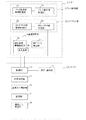
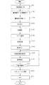
1枚のフィルムに記録する駒数が1駒の場合は、図11のフローチャート図に従って処理される。まず、ステップS201で、画像サイズ、画像読影向き、駒数を入力パラメータとして設定する。この入力パラメータは表示・操作部12を用いてオペレータが入力してもよいが、画像サイズ及び画像読影向きに関しては、リーダー2から取得することもできるし、駒数に関しては画像確認/出力画面21の画像表示欄23の中から選択した画像の数が駒数として設定することもできる。
[In the case of one frame]
When the number of frames to be recorded on one film is 1, the processing is performed according to the flowchart of FIG. First, in step S201, an image size, an image interpretation direction, and the number of frames are set as input parameters. The input parameters may be input by the operator using the display /
次に、画像出力制御部13は、リーダー2から画像が記録されたカセッテ17のサイズ(8インチ×10インチ)を取得し、画像の短辺(a)=8インチ、長辺(b)=10インチと設定する。
Next, the image
次に、ステップS202で、画像出力制御部13は、コントローラー3に接続されているプリンタから、該プリンタに装填されているフィルムの種類を取得し、ステップS203で、その中から最小サイズのフィルムを選択し、ステップS204で、選択されたフィルムの短辺(a’)及び長辺(b’)を決定する。この場合、まず最小サイズの六切サイズで設定を行い、短辺(a’)=8インチ、長辺(b’)=10インチとする。
Next, in step S202, the image
次に、ステップS205で、画像の短辺(a)とフィルムの短辺(a’)、画像の長辺(b)とフィルムの長辺(b’)とを各々比較し、a’≧a、かつ、b’≧bの関係を満足するか否かを判断し、満足する場合は、選択されたフィルムを出力するフィルムとして設定し、満足しない場合は、ステップS206で、プリンタに装填されているフィルムの中で次に大きいサイズのフィルムを選択する。そして、選択したフィルムがプリンタに装填されている最大のフィルムでない場合は同様にステップS204、S205の処理を行い、最大のフィルムの場合は該フィルムを出力するフィルムとして設定する。そして、ステップS208で設定されたフィルムのサイズを決定する。 In step S205, the short side (a) of the image is compared with the short side (a ′) of the film, and the long side (b) of the image is compared with the long side (b ′) of the film. In addition, it is determined whether or not the relationship b ′ ≧ b is satisfied. If satisfied, the selected film is set as an output film, and if not satisfied, it is loaded into the printer in step S206. The next largest film is selected among the existing films. If the selected film is not the maximum film loaded in the printer, the processes in steps S204 and S205 are similarly performed. If the selected film is the maximum film, the film is set as an output film. Then, the film size set in step S208 is determined.
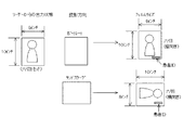
次に、ステップS209で、リーダー2で読取られた画像を、垂直方向(ポートレート)で読影するか、水平方向(ランドスケープ)で読影するかの読影方向のうちの選択された読影方向に基づいて、水平方向の画像長さと垂直方向の画像長さを定め、この読影方向に基づく両方向の長さと選択されたサイズのフィルム(六切)の短辺を水平方向とした場合の水平方向長さ(8インチ)と垂直方向長さ(10インチ)及び長辺を水平方向として場合の水平方向長さ(10インチ)と垂直方向長さ(8インチ)を比較し、最も形状が近い、換言すると縦横比の差が少ない方向をフィルム向きとして選択する。
Next, in step S209, the image read by the
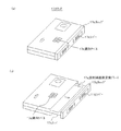
この一連の動作を模式的に示すと図13のようになり、リーダー2に挿入されたカセッテ17が六切カセッテの場合は、リーダー2から出力される画像は短辺が8インチ、長辺が10インチになり、読影方向がポートレート方向の場合は縦向きの六切フィルム(六切フィルムがプリンタに装填されていない場合は順に大きいサイズのフィルム)が選択され、読影方向がランドスケープ方向の場合は横向きの六切フィルム(同様に六切フィルムがプリンタに装填されていない場合は順に大きいサイズのフィルム)が選択されて画像が出力される。尚、フィルムへの出力時、リーダー2で読取られ画像処理された画像データをDICOM規格に則り、フィルムサイズ情報及びポートレートと指定して、DICOMイメージャーへ送信すると、当該画像データを受信したDICOMイメージャーはフィルムサイズを選定し、選定されたサイズにおける画像データ書き込み位置及び患者ID書き込み位置を制御する。この結果、選択した読影方向で、患者IDが正常に判読可能な方向となる。
This series of operations is schematically shown in FIG. 13. When the
[2駒の場合]
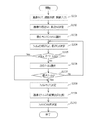
また、1枚のフィルムに記録する駒数が2駒の場合は、図12のフローチャート図に従って処理される。まず、ステップS301で、画像サイズ、画像読影向き、駒数を入力パラメータとして設定する。次に、2駒の場合は2つの画像を横(左右)に配置するか、縦(上下)に配列するかの2通りが考えられるため、各々の配列方向に対して以下の手順でフィルムサイズを決定する。
[In case of 2 frames]
If the number of frames to be recorded on one film is two, the processing is performed according to the flowchart of FIG. First, in step S301, an image size, an image interpretation direction, and the number of frames are set as input parameters. Next, in the case of two frames, two images can be considered: two images are arranged horizontally (left and right) or vertically (up and down), so the film size is set by the following procedure for each arrangement direction. decide.
読影方向がポートレート指定を例として説明する。まず、横方向に配列する場合は、ステップS303で、画像出力制御部13は、リーダー2から画像が記録されたカセッテ17のサイズを取得し、当該2駒の画像を横(左右)方向に画像全体の短辺(a1)=10インチおよび長辺(b1)=16インチと設定する。また、ステップS304で、画像出力制御部13は、コントローラー3に接続されているプリンタから、該プリンタに装填されているフィルムの種類を取得し、ステップS304で、その中から最小サイズのフィルムを選択し、ステップS305で、選択されたフィルムの短辺(a’)及び長辺(b’)を特定する。
A description will be given by taking the portrait direction as an example of the interpretation direction. First, in the case of arranging in the horizontal direction, in step S303, the image
次に、ステップS306で、画像の短辺(a1)とフィルムの短辺(a’)、画像の長辺(b1)とフィルムの長辺(b’)とを各々比較し、a’≧a1、かつ、b’≧b1の関係を満足するか否かを判断し、満足する場合は、選択されたフィルムを出力するフィルムとして設定し、満足しない場合は、ステップS307で、プリンタに装填されているフィルムの中で次に大きいサイズのフィルムを選択する。そして、選択したフィルムがプリンタに装填されている最大のフィルムでない場合は、同様にステップS305、S306の処理を行い、最大のフィルムの場合はステップS309で該フィルムを出力するフィルムとして設定する。 Next, in step S306, the short side (a1) of the image is compared with the short side (a ′) of the film, the long side (b1) of the image is compared with the long side (b ′) of the film, and a ′ ≧ a1. In addition, it is determined whether or not the relationship b ′ ≧ b1 is satisfied. If satisfied, the selected film is set as an output film, and if not satisfied, it is loaded in the printer in step S307. The next largest film is selected among the existing films. If the selected film is not the maximum film loaded in the printer, the processes in steps S305 and S306 are performed in the same manner. If the selected film is the maximum film, the film is set as an output film in step S309.
次に、縦方向に配列する場合は、ステップS303’で、画像出力制御部13は、リーダー2から画像が記録されたカセッテ17のサイズを取得し、当該2駒の画像を縦(上下)方向に画像全体の短辺(a2)=8インチおよび長辺(b2)=20インチと設定する。また、ステップS304’で、画像出力制御部13は、コントローラー3に接続されているプリンタから、該プリンタに装填されているフィルムの種類を取得し、ステップS304’で、その中から最小サイズのフィルムを選択し、ステップS305で、選択されたフィルムの短辺(a’)及び長辺(b’)を決定する。
Next, in the case of arranging in the vertical direction, in step S303 ′, the image
次に、ステップS306’で、画像の短辺(a2)とフィルムの短辺(a’)、画像の長辺(b2)とフィルムの長辺(b’)とを各々比較し、a’≧a2、かつ、b’≧b2の関係を満足するか否かを判断し、満足する場合は、選択されたフィルムを出力するフィルムに設定し、満足しない場合は、ステップS307’で、プリンタに装填されているフィルムの中で次に大きいサイズのフィルムを選択する。そして、選択したフィルムがプリンタに装填されている最大のフィルムでない場合は、同様にステップS305’、S306’の処理を行い、最大のフィルムの場合はステップS309’で該フィルムを出力するフィルムとして設定する。 Next, in step S306 ′, the short side (a2) of the image is compared with the short side (a ′) of the film, the long side (b2) of the image is compared with the long side (b ′) of the film, and a ′ ≧ It is determined whether or not the relationship of a2 and b ′ ≧ b2 is satisfied. If satisfied, the selected film is set as a film to be output, and if not satisfied, it is loaded into the printer in step S307 ′. The next largest film is selected among the films that have been used. If the selected film is not the maximum film loaded in the printer, the processes in steps S305 ′ and S306 ′ are performed in the same manner. If the selected film is the maximum film, the film is set as an output film in step S309 ′. To do.
次に、ステップS310で、横配列と縦配列の各々で設定されたフィルムを比較し、2つのフィルムの中から小さいサイズのフィルム及びフィルムの分割方向(画像の配列方向)を選択する。また、フィルムサイズが同一の場合は、より形状が近い(縦横比の差が少ない)フィルム及びフィルムの分割方向(画像の配列方向)を選択する。上記例の場合、横配列でのフィルムサイズは半切が条件に合致し選択され、縦配列の場合、合致する条件のサイズが存在しないので、最大サイズとして半切が選択される。そして、分割方向は、選択されたサイズのフィルム(半切)と縦横比の差が少ない横配列が選ばれる。尚、フィルムサイズの選択が、合致するものなく最大サイズとして選択された場合には、画像全体を出力できないことを意味するので、全体出力可能な自動倍率変換もしくは、倍率は変更せずに画像の出力範囲(領域)を前述した出力プロパティ画面で選択する(狭くする)と良い。 Next, in step S310, the film set in each of the horizontal arrangement and the vertical arrangement is compared, and a small size film and a film dividing direction (image arrangement direction) are selected from the two films. When the film sizes are the same, the film and the film dividing direction (image arrangement direction) that are closer in shape (the difference in aspect ratio is small) are selected. In the case of the above example, the half-cut film size in the horizontal arrangement is selected in accordance with the conditions, and in the vertical arrangement, since the size of the matching conditions does not exist, the half-cut is selected as the maximum size. As the dividing direction, a horizontal arrangement having a small difference in aspect ratio from the selected size film (half cut) is selected. If the film size is selected as the maximum size without a match, it means that the entire image cannot be output. Therefore, automatic magnification conversion that can output the entire image or the magnification of the image is not changed. It is better to select (narrow) the output range (area) on the output property screen described above.
次に、ステップS311で、各駒画像の読影方向に基づいた水平方向長さ(8インチ)及び垂直方向長さ(10インチ)と、選択された半切フィルムの短辺を水平方向とし左右に2分割した1/2の領域の水平方向長さ(7インチ)及び垂直方向長さ(17インチ)、及び、選択された半切フィルムの長辺を水平方向とし左右に2分割した1/2の領域の水平方向長さ(8.5インチ)及び垂直方向長さ(14インチ)、を比較し、最も形状が近い、換言すると縦横比の差が少ない方向をフィルム向きとして選択する。この場合、長辺を水平方向とするフィルム向きが選択される。 Next, in step S311, the horizontal length (8 inches) and the vertical length (10 inches) based on the interpretation direction of each frame image, and the short side of the selected half-cut film as the horizontal direction are set to 2 left and right. The horizontal length (7 inches) and vertical length (17 inches) of the divided half area, and the half area obtained by dividing the long side of the selected half-cut film horizontally into the left and right parts The horizontal length (8.5 inches) and the vertical length (14 inches) are compared, and the direction closest to the shape, in other words, the direction with the smallest difference in aspect ratio is selected as the film orientation. In this case, the film orientation with the long side in the horizontal direction is selected.
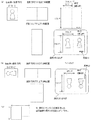
この一連の動作を模式図に示すと図14のようになる。尚、フィルムへの出力時、リーダー2で読取られ画像処理された画像データをDICOM規格に則り、フィルムサイズ情報、駒数情報及びポートレートと指定して、DICOMイメージャーへ送信すると、当該画像データを受信したDICOMイメージャーはフィルムサイズ選定し、選定されたサイズにおける画像データ書き込み位置及び患者ID書き込み位置を制御する。この結果、選択した読影方向で、患者IDが正常に判読可能な方向となる。
This series of operations is schematically shown in FIG. When output to film, the image data read and processed by the
[4駒の場合]
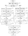
また、1枚のフィルムに記録する駒数が4駒の場合は、1駒の場合と同様に、図11のフローチャート図に従って処理される。まず、ステップS201で、画像サイズ、画像読影向き、駒数を入力パラメータとして設定する。
[In case of 4 frames]
Further, when the number of frames to be recorded on one film is 4, processing is performed according to the flowchart of FIG. 11 as in the case of 1 frame. First, in step S201, an image size, an image interpretation direction, and the number of frames are set as input parameters.
次に、ステップS202で、画像出力制御部13は、リーダー2から画像が記録されたカセッテ17のサイズを取得し、カセッテ17のサイズのポートレート方向の4駒の画像を2×2に配列した画像全体の短辺(a)及び長辺(b)を決定する。
Next, in step S202, the image
次に、画像出力制御部13は、コントローラー3に接続されているプリンタから、該プリンタに装填されているフィルムの種類を取得し、ステップS203で、その中から最小サイズのフィルムを選択し、ステップS204で、選択されたフィルムの短辺(a’)及び長辺(b’)を特定する。
Next, the image
次に、ステップS205で、画像の短辺(a)とフィルムの短辺(a’)、画像の長辺(b)とフィルムの長辺(b’)とを各々比較し、a’≧a、かつ、b’≧bの関係を満足するか否かを判断し、満足する場合は、選択されたフィルムを出力するフィルムに設定し、満足しない場合は、ステップS206で、プリンタに装填されているフィルムの中で次に大きいサイズのフィルムを選択する。そして、選択したフィルムがプリンタに装填されている最大のフィルムでない場合は、同様にステップS204、S205の処理を行い、最大のフィルムの場合はステップS208で該フィルムを出力するフィルムとして設定する。 In step S205, the short side (a) of the image is compared with the short side (a ′) of the film, and the long side (b) of the image is compared with the long side (b ′) of the film. In addition, it is determined whether or not the relationship of b ′ ≧ b is satisfied. If satisfied, the selected film is set as the output film. If not satisfied, it is loaded in the printer in step S206. The next largest film is selected among the existing films. If the selected film is not the maximum film loaded in the printer, the processing in steps S204 and S205 is performed in the same manner. If the selected film is the maximum film, the film is set as a film to be output in step S208.
次に、ステップS209で、フィルム縦向きでの1/4サイズと、そのエリアに記録されるポートレート方向の画像との形状の近さ(縦横比の差)を評価すると共に、フィルム横向きでの1/4サイズと、そのエリアに記録されるポートレート方向の画像との形状の近さ(縦横比の差)を評価し、フィルム縦向きと横向きとで求めた形状の近さを同一駒間で比較し、ステップS210で、より形状が近い(縦横比の差が少ない)駒数が多い向きを選択する。また、駒数が同じ場合は、フィルムの縦向きでの各駒の縦横比の差の合計とフィルム横向きでの各駒の縦横比の差の合計を比較し、少ない向きを選択する。この場合、合致する条件のサイズが存在しないので、最大サイズとして半切が選択される。尚、フィルムサイズの選択が、合致するものなく最大サイズとして選択された場合には、画像全体を出力できないことを意味するので、全体出力可能な自動倍率変換もしくは、倍率は変更せずに画像の出力範囲(領域)を前述した出力プロパティ画面で選択(狭くする)すると良い。 Next, in step S209, the closeness of the shape (difference in aspect ratio) between the 1/4 size in the portrait direction of the film and the portrait image recorded in the area is evaluated, and the landscape orientation of the film is Evaluate the closeness (difference in aspect ratio) between the 1/4 size and the portrait-oriented image recorded in the area, and determine the closeness of the shape in the vertical and horizontal directions between the same frames. In step S210, the direction with the larger number of frames that is closer in shape (smaller in the aspect ratio) is selected. When the number of frames is the same, the total difference in the aspect ratio of each frame in the vertical direction of the film is compared with the total difference in the aspect ratio of each frame in the horizontal direction of the film, and a smaller direction is selected. In this case, since there is no matching size size, half-cut is selected as the maximum size. If the film size is selected as the maximum size without a match, it means that the entire image cannot be output. Therefore, automatic magnification conversion that can output the entire image or the magnification of the image is not changed. The output range (area) may be selected (narrowed) on the output property screen described above.
この一連の動作を模式的に示すと図15のようになり、リーダー2に挿入されたカセッテ17が六切カセッテの場合は、4駒(2×2駒)に配列した画像は短辺が16インチ、長辺が20インチになり、フィルムとして半切(半切フィルムがプリンタに装填されていない場合は順に大きいサイズのフィルム)が選択され、フィルムの向きを縦向きにした場合は1駒の画像の領域が7インチ(短辺)×8.5インチ(長辺)、横向きにした場合は1駒の画像の領域が8.5インチ(短辺)×7インチ(長辺)になり、より1駒の画像の縦横比に近い横向きが選択されて画像が出力される。
This series of operations is schematically shown in FIG. 15. When the
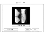
そして、画像出力制御部13で出力条件が自動的に設定される場合は、画像表示欄23の各画像の周辺に設けられたOKボタンを選択すると、OKボタンが押下された該画像データはデフォルト出力フォーマットキューに入れられる。このとき、デフォルト出力フォーマットキューの中に保持された画像データ数が、デフォルト出力フォーマットボタンにて指定されたフォーマットが必要とする画像データ数に一致するなら、図7に示す当該フォーマットのフィルム出力イメージを表すプリントプレビュー画面26を表示する。
When the output condition is automatically set by the image
プリントプレビュー画面26では、OKボタンが押されると、図10のステップS113で表示された出力イメージの画像データがレーザーイメージャー等のプリンタに出力され、図7に示すプリントプレビュー画面26は閉じられる。このときプリンタ等に出力された画像データは、デフォルト出力フォーマットキューから取り出される。プリントプレビュー画面26で、キャンセルボタンが押された場合はプリンタへの出力は行わず、プリントプレビュー画面26のみが閉じられる。このとき、画像確認/出力画面21の画像表示欄23で最後にOKボタンを押下した画像データは、デフォルト出力フォーマットキューから取り出される。 In the print preview screen 26, when the OK button is pressed, the image data of the output image displayed in step S113 in FIG. 10 is output to a printer such as a laser imager, and the print preview screen 26 shown in FIG. 7 is closed. At this time, the image data output to the printer or the like is extracted from the default output format queue. If the cancel button is pressed on the print preview screen 26, output to the printer is not performed, and only the print preview screen 26 is closed. At this time, the image data for which the OK button was last pressed in the image display field 23 of the image confirmation / output screen 21 is taken out from the default output format queue.
そして検査終了ボタンが押下されると、初期画面へと遷移するが、このとき、未だ出力されていない画像に対しては、画像確認/出力画面21のデフォルト出力フォーマットボタンで指定されたフォーマットに従い、順次画像データが配置されて、出力される。 When the examination end button is pressed, the screen transitions to the initial screen. At this time, for an image that has not yet been output, according to the format specified by the default output format button of the image confirmation / output screen 21, Image data is sequentially arranged and output.
このように、本実施例の画像出力制御方法及び画像出力制御プログラムによれば、画像サイズ(カセッテ17のサイズ)、画像読影向き、画像の駒数を入力パラメータとして、出力するフィルムのサイズ、フィルムの向き、フィルムの分割方向が自動的に設定されるため、医用画像を出力するたびにオペレータが出力条件を設定する必要がなくなり、操作性を格段に向上させることができる。 As described above, according to the image output control method and the image output control program of this embodiment, the image size (the size of the cassette 17), the image interpretation direction, and the number of frames of the image are used as input parameters. Since the direction and the film dividing direction are automatically set, it is not necessary for the operator to set the output condition each time a medical image is output, and the operability can be greatly improved.
1 放射線画像診断システム
2 画像読み取り装置(リーダー)
3 制御装置(コントローラー)
4 撮影装置
5 スイッチングHUB
6a 患者受付端末
6b ビューアー
6c プリンタ
7 プレート制御部
7a プレート搬送部機構駆動部
7b プレート搬送部制御部
8 カセッテスタッカ部
8a カセッテスタッカ部機構駆動部
8b カセッテスタッカ部制御部
9 画像読取部
9a 副走査部機構駆動部
9b 主走査部
9c 識別ラベル検出部
10 制御部
11 演算処理部
12 表示・操作部
13 表示制御部
14 記憶部
15 識別ラベル検出部
16 放射線源
17 カセッテ
17a 放射線画像変換プレート
17b キャップ
17c トレイ
17d レバー
17e 識別ラベル
18 輝尽蛍光体シート
19 ジョブマネージャー
20 スタディマネージャー
21 画像確認/出力画面
22 撮影部位選択欄
22a 人体モデル
22b 部位選択ボタン
23 画像表示欄
23a 出力フォーマット切替ボタン
23b ページ切替ボタン
24 画像処理条件調整欄
24a 処理パラメータ設定ボタン
24b 処理パラメータ初期化ボタン
25 出力欄
25a デフォルト出力フォーマットボタン
26 プリントプレビュー画面
27 出力プロパティ画面
27a 画像リスト表示部
27b プレビュー表示部
28 出力プロパティ画面
28a 画像リスト表示部
28b プレビュー表示部
29 出力済みマーク
1 Radiological
3 Controller (Controller)
4 Shooting device 5 Switching HUB
6a
Claims (10)
前記放射線画像のサイズ、前記放射線画像の読影向き及び1枚のフィルムに記録する前記放射線画像の駒数を入力パラメータとして、予め定められた手順に従って、1駒又は複数駒の前記放射線画像を記録する前記フィルムのサイズ、前記フィルムの向き及び複数駒の前記放射線画像を記録する場合における前記フィルムの分割方向を自動的に設定することを特徴とする画像出力制御方法。 An image output control method in a medical image system having a function of outputting a radiographic image obtained by photographing a subject to a film,
The radiographic image of one or more frames is recorded according to a predetermined procedure using the size of the radiographic image, the interpretation direction of the radiographic image, and the number of frames of the radiographic image to be recorded on one film as input parameters. An image output control method comprising: automatically setting a film size, a film orientation, and a direction in which the film is divided when a plurality of frames of radiographic images are recorded.
1駒の前記放射線画像又は配列された複数駒の前記放射線画像全体の短辺(a)及び長辺(b)を取得する第1のステップと、
プリンタに装填されているフィルムの内、最小サイズのフィルムを選択する第2のステップと、
選択された前記フィルムの短辺(a’)及び長辺(b’)を取得する第3のステップと、
aとa’、bとb’とを各々比較し、a’≧a、かつ、b’≧bの関係を満足するか否かを判定する第4のステップと、
前記関係を満足する場合は前記選択されたフィルムを前記1駒又は複数駒の放射線画像を記録するフィルムとして特定し、前記関係を満足しない場合は次に大きいサイズのフィルムを選択して前記第3のステップ以降を実行する第5のステップと、を実行することを特徴とする請求項1記載の画像出力制御方法。 In setting the film size,
A first step of acquiring a short side (a) and a long side (b) of the whole radiographic image of the radiographic image of one frame or a plurality of arranged frames;
A second step of selecting a minimum size film among the films loaded in the printer;
A third step of obtaining a short side (a ′) and a long side (b ′) of the selected film;
a fourth step of comparing a and a ′, b and b ′, respectively, and determining whether or not a relationship of a ′ ≧ a and b ′ ≧ b is satisfied;
If the relationship is satisfied, the selected film is specified as a film for recording the radiation image of one or more frames. If the relationship is not satisfied, the next largest film is selected and the third film is selected. The image output control method according to claim 1, further comprising: a fifth step that executes the subsequent steps.
前記放射線画像が4駒の場合は、該4駒の放射線画像各々の読影方向を維持しながら2行2列に配列した画像全体に対して出力するフィルムを特定することを特徴とする請求項2記載の画像出力制御方法。 When the radiographic image is two frames, the film is identified and specified for both the case where the radiographic images are arranged in the horizontal direction and the case where they are arranged in the vertical direction while maintaining the interpretation direction of each of the radiographic images of the two frames. If the two film sizes are different, the small film size is specified as the film for recording the two radiographic images, and the film dividing direction is set according to the arrangement direction of the radiographic images,
The film to be output is specified for the entire image arranged in 2 rows and 2 columns while maintaining the interpretation direction of each of the four radiographic images when the radiographic image is four frames. Image output control method.
前記特定されたフィルムの中の1駒の前記放射線画像が記録される領域の縦横比と、前記読影向きにおける前記放射線画像の縦横比とを比較し、該縦横比の差を用いてフィルムの向きを設定することを特徴とする請求項1乃至3のいずれか一に記載の画像出力制御方法。 When setting the orientation of the film,
The aspect ratio of the region of the specified film where the radiographic image is recorded is compared with the aspect ratio of the radiographic image in the interpretation direction, and the orientation of the film is determined using the difference in the aspect ratio. The image output control method according to claim 1, wherein the image output control method is set.
前記放射線画像が2駒の場合は、前記特定されたフィルムを縦向きにした場合の1/2の領域の縦横比と、該1/2の領域に記録される前記読影向きにおける1駒の前記放射線画像の縦横比とを比較すると共に、前記特定されたフィルムを横向きにした場合の1/2の領域の縦横比と、該1/2の領域に記録される前記読影向きにおける1駒の前記放射線画像の縦横比とを比較して、該縦横比の差の合計が少ない方をフィルムの向きとして設定し、
前記放射線画像が4駒の場合は、前記特定されたフィルムを縦向きにした場合の1/4の領域の縦横比と、該1/4の領域に記録される前記読影向きにおける1駒の前記放射線画像の縦横比とを比較すると共に、前記特定されたフィルムを横向きにした場合の1/4の領域の縦横比と、該1/4の領域に記録される前記読影向きにおける1駒の前記放射線画像の縦横比とを比較して、縦横比の差の合計が少ない方をフィルムの向きとして設定することを特徴とする請求項4記載の画像出力制御方法。 If the radiographic image is one frame, set the orientation of the film by comparing the aspect ratio of the whole specified film and the aspect ratio of the radiographic image of the one frame in the interpretation direction,
When the radiographic image is two frames, the aspect ratio of a half area when the specified film is oriented vertically and the radiographic image of one frame in the interpretation direction recorded in the half area The aspect ratio of a half area when the specified film is turned sideways, and the radiation image of one frame in the interpretation direction recorded in the half area are compared with each other. Compare the aspect ratio and set the direction with the smaller difference of the aspect ratio as the film orientation.
When the radiographic image is four frames, the aspect ratio of the 1/4 area when the specified film is oriented vertically and the radiographic image of one frame in the interpretation direction recorded in the 1/4 area The aspect ratio of the 1/4 area when the specified film is turned sideways and the radiographic image of one frame in the interpretation direction recorded in the 1/4 area are compared with each other. 5. The image output control method according to claim 4, wherein the direction of the film is set as a direction having a smaller total difference of the aspect ratios by comparing with the aspect ratio.
コンピュータを、
前記放射線画像のサイズ、前記放射線画像の読影向き及び1枚のフィルムに記録する前記放射線画像の駒数を入力パラメータとして、予め定められた手順に従って、1駒又は複数駒の前記放射線画像を記録する前記フィルムのサイズ、前記フィルムの向き及び複数駒の前記放射線画像を記録する場合における前記フィルムの分割方向を自動的に設定する画像出力制御手段として機能させることを特徴とする画像出力制御プログラム。 An image output control program for operating a medical image system having a function of outputting a radiographic image obtained by photographing a subject to a film,
Computer
The radiographic image of one or more frames is recorded according to a predetermined procedure using the size of the radiographic image, the interpretation direction of the radiographic image, and the number of frames of the radiographic image to be recorded on one film as input parameters. An image output control program that functions as an image output control means for automatically setting a film size, a film orientation, and a division direction of the film when a plurality of frames of radiographic images are recorded.
1駒の前記放射線画像又は配列された複数駒の前記放射線画像全体の短辺(a)及び長辺(b)を取得する第1の処理と、
プリンタに装填されているフィルムの内、最小サイズのフィルムを選択する第2の処理と、
選択された前記フィルムの短辺(a’)及び長辺(b’)を取得する第3の処理と、
aとa’、bとb’とを各々比較し、a’≧a、かつ、b’≧bの関係を満足するか否かを判定する第4の処理と、
前記関係を満足する場合は前記選択されたフィルムを前記1駒又は複数駒の放射線画像を記録するフィルムとして特定し、前記関係を満足しない場合は次に大きいサイズのフィルムを選択して前記第3の処理以降を実行する第5の処理とを実行することを特徴とする請求項6記載の画像出力制御プログラム。 The image output control means, when setting the film size,
A first process of acquiring a short side (a) and a long side (b) of the whole radiographic image of the radiographic image of one frame or a plurality of arranged frames;
A second process of selecting the smallest film among the films loaded in the printer;
A third process for obtaining a short side (a ′) and a long side (b ′) of the selected film;
a fourth process for comparing a and a ′, b and b ′, respectively, and determining whether or not a relationship of a ′ ≧ a and b ′ ≧ b is satisfied;
If the relationship is satisfied, the selected film is specified as a film for recording the radiation image of one or more frames. If the relationship is not satisfied, the next largest film is selected and the third film is selected. The image output control program according to claim 6, wherein a fifth process that executes the subsequent processes is executed.
前記放射線画像が2駒の場合は、該2駒の放射線画像各々の読影方向を維持しながら左右方向に配列した場合と上下方向に配列した場合の双方に対して、前記フィルムの特定を行い、特定された2つのフィルムのサイズが異なる場合は、小さいサイズのフィルムを前記2駒の放射線画像を記録するフィルムとして特定すると共に、前記放射線画像の配列方向に従って前記フィルムの分割方向を設定し、
前記放射線画像が4駒の場合は、該4駒の放射線画像各々の読影方向を維持しながら2行2列に配列した画像全体に対して出力するフィルムを特定する制御を行うことを特徴とする請求項7記載の画像出力制御プログラム。 The image output control means includes
When the radiographic image is two frames, the film is identified and specified for both the case where the radiographic images are arranged in the horizontal direction and the case where they are arranged in the vertical direction while maintaining the interpretation direction of each of the radiographic images of the two frames. If the two film sizes are different, the small film size is specified as the film for recording the two radiographic images, and the film dividing direction is set according to the arrangement direction of the radiographic images,
When the radiation image is four frames, control is performed to specify a film to be output for the entire image arranged in two rows and two columns while maintaining the interpretation direction of each of the four radiation images. 7. The image output control program according to 7.
前記特定されたフィルムの中の1駒の前記放射線画像が記録される領域の縦横比と、前記読影向きにおける前記放射線画像の縦横比とを比較し、該縦横比の差を用いてフィルムの向きを設定する制御を行うことを特徴とする請求項6乃至8のいずれか一に記載の画像出力制御プログラム。 The image output control means, when setting the direction of the film,
The aspect ratio of the region of the specified film where the radiographic image is recorded is compared with the aspect ratio of the radiographic image in the interpretation direction, and the orientation of the film is determined using the difference in the aspect ratio. The image output control program according to any one of claims 6 to 8, wherein control for setting is performed.
前記放射線画像が1駒の場合は、前記特定されたフィルム全体の縦横比と、前記読影向きにおける該1駒の前記放射線画像の縦横比とを比較してフィルムの向きを設定し、
前記放射線画像が2駒の場合は、前記特定されたフィルムを縦向きにした場合の1/2の領域の縦横比と、該1/2の領域に記録される前記読影向きにおける1駒の前記放射線画像の縦横比とを比較すると共に、前記特定されたフィルムを横向きにした場合の1/2の領域の縦横比と、該1/2の領域に記録される前記読影向きにおける1駒の前記放射線画像の縦横比とを比較して、該縦横比の差の合計が少ない方をフィルムの向きとして設定し、
前記放射線画像が4駒の場合は、前記特定されたフィルムを縦向きにした場合の1/4の領域の縦横比と、該1/4の領域に記録される前記読影向きにおける1駒の前記放射線画像の縦横比とを比較すると共に、前記特定されたフィルムを横向きにした場合の1/4の領域の縦横比と、該1/4の領域に記録される前記読影向きにおける1駒の前記放射線画像の縦横比とを比較して、縦横比の差の合計が少ない方をフィルムの向きとして設定する制御を行うことを特徴とする請求項9記載の画像出力制御プログラム。 The image output control means includes
If the radiographic image is one frame, set the orientation of the film by comparing the aspect ratio of the whole specified film and the aspect ratio of the radiographic image of the one frame in the interpretation direction,
When the radiographic image is two frames, the aspect ratio of a half area when the specified film is oriented vertically and the radiographic image of one frame in the interpretation direction recorded in the half area The aspect ratio of a half area when the specified film is turned sideways, and the radiation image of one frame in the interpretation direction recorded in the half area are compared with each other. Compare the aspect ratio and set the direction with the smaller difference of the aspect ratio as the film orientation.
When the radiographic image is four frames, the aspect ratio of the 1/4 area when the specified film is oriented vertically and the radiographic image of one frame in the interpretation direction recorded in the 1/4 area The aspect ratio of the 1/4 area when the specified film is turned sideways and the radiographic image of one frame in the interpretation direction recorded in the 1/4 area are compared with each other. The image output control program according to claim 9, wherein the image output control program performs control for comparing the aspect ratio and setting the direction having the smaller difference in aspect ratio as the film orientation.
Priority Applications (2)
| Application Number | Priority Date | Filing Date | Title |
|---|---|---|---|
| JP2004112902A JP2005296091A (en) | 2004-04-07 | 2004-04-07 | Image output control method and program |
| US11/095,875 US20050227154A1 (en) | 2004-04-07 | 2005-03-31 | Image output controlling method and image output controlling program |
Applications Claiming Priority (1)
| Application Number | Priority Date | Filing Date | Title |
|---|---|---|---|
| JP2004112902A JP2005296091A (en) | 2004-04-07 | 2004-04-07 | Image output control method and program |
Publications (2)
| Publication Number | Publication Date |
|---|---|
| JP2005296091A true JP2005296091A (en) | 2005-10-27 |
| JP2005296091A5 JP2005296091A5 (en) | 2007-05-10 |
Family
ID=35060924
Family Applications (1)
| Application Number | Title | Priority Date | Filing Date |
|---|---|---|---|
| JP2004112902A Pending JP2005296091A (en) | 2004-04-07 | 2004-04-07 | Image output control method and program |
Country Status (2)
| Country | Link |
|---|---|
| US (1) | US20050227154A1 (en) |
| JP (1) | JP2005296091A (en) |
Cited By (2)
| Publication number | Priority date | Publication date | Assignee | Title |
|---|---|---|---|---|
| JP2010082330A (en) * | 2008-10-01 | 2010-04-15 | Canon Inc | Information processing device, display method therefor, and program |
| JP2011067314A (en) * | 2009-09-25 | 2011-04-07 | Fujifilm Corp | Cassette for radiographic imaging and radiographic imaging system |
Families Citing this family (7)
| Publication number | Priority date | Publication date | Assignee | Title |
|---|---|---|---|---|
| JP2004287040A (en) * | 2003-03-20 | 2004-10-14 | Fuji Photo Film Co Ltd | Method and apparatus for managing image recording medium |
| JP4730211B2 (en) * | 2006-05-31 | 2011-07-20 | 横河電機株式会社 | Data processing apparatus and data processing method |
| US8295568B2 (en) * | 2006-06-30 | 2012-10-23 | Fujifilm Corporation | Medical image display processing apparatus and medical image display processing program |
| JP4829163B2 (en) * | 2007-03-30 | 2011-12-07 | 富士フイルム株式会社 | Radiation image capturing apparatus and radiation image capturing method |
| JP5746513B2 (en) | 2011-01-27 | 2015-07-08 | 富士フイルム株式会社 | Radiography system and console |
| JP2017004175A (en) * | 2015-06-08 | 2017-01-05 | キヤノン株式会社 | Management system and control method thereof, information processing device, and program |
| US20180008216A1 (en) * | 2016-07-07 | 2018-01-11 | Samsung Electronics Co., Ltd. | X-ray detector, and x-ray imaging apparatus having the same |
Citations (4)
| Publication number | Priority date | Publication date | Assignee | Title |
|---|---|---|---|---|
| JPH0267077A (en) * | 1988-08-31 | 1990-03-07 | Fuji Photo Film Co Ltd | Image recorder |
| JPH03142574A (en) * | 1989-10-27 | 1991-06-18 | Fuji Photo Film Co Ltd | Video signal processor |
| JPH1127505A (en) * | 1997-06-30 | 1999-01-29 | Murata Mach Ltd | Recording device with communication function |
| JP2000115514A (en) * | 1998-09-30 | 2000-04-21 | Canon Inc | Picture processor and its method |
Family Cites Families (3)
| Publication number | Priority date | Publication date | Assignee | Title |
|---|---|---|---|---|
| US3859527A (en) * | 1973-01-02 | 1975-01-07 | Eastman Kodak Co | Apparatus and method for producing images corresponding to patterns of high energy radiation |
| US5214519A (en) * | 1991-04-29 | 1993-05-25 | E. I. Du Pont De Nemours And Company | Method and apparatus for producing a specified format output image from an arbitrary format source image |
| US5734915A (en) * | 1992-11-25 | 1998-03-31 | Eastman Kodak Company | Method and apparatus for composing digital medical imagery |
-
2004
- 2004-04-07 JP JP2004112902A patent/JP2005296091A/en active Pending
-
2005
- 2005-03-31 US US11/095,875 patent/US20050227154A1/en not_active Abandoned
Patent Citations (4)
| Publication number | Priority date | Publication date | Assignee | Title |
|---|---|---|---|---|
| JPH0267077A (en) * | 1988-08-31 | 1990-03-07 | Fuji Photo Film Co Ltd | Image recorder |
| JPH03142574A (en) * | 1989-10-27 | 1991-06-18 | Fuji Photo Film Co Ltd | Video signal processor |
| JPH1127505A (en) * | 1997-06-30 | 1999-01-29 | Murata Mach Ltd | Recording device with communication function |
| JP2000115514A (en) * | 1998-09-30 | 2000-04-21 | Canon Inc | Picture processor and its method |
Cited By (4)
| Publication number | Priority date | Publication date | Assignee | Title |
|---|---|---|---|---|
| JP2010082330A (en) * | 2008-10-01 | 2010-04-15 | Canon Inc | Information processing device, display method therefor, and program |
| US8665490B2 (en) | 2008-10-01 | 2014-03-04 | Canon Kabushiki Kaisha | Information processing apparatus, display method therefor, and computer-readable storage medium |
| JP2011067314A (en) * | 2009-09-25 | 2011-04-07 | Fujifilm Corp | Cassette for radiographic imaging and radiographic imaging system |
| US8616766B2 (en) | 2009-09-25 | 2013-12-31 | Fujifilm Corporation | Cassette for radiographic imaging and cassette loading orientation detection device |
Also Published As
| Publication number | Publication date |
|---|---|
| US20050227154A1 (en) | 2005-10-13 |
Similar Documents
| Publication | Publication Date | Title |
|---|---|---|
| US7769602B2 (en) | Medical image creating system, medical image creating method and display controlling program | |
| US7162068B2 (en) | Medical image displaying device, image obtaining and displaying device, method for displaying image in displaying device, and program for selecting display format | |
| US6501827B1 (en) | Examination system, image processing apparatus and method, medium, and x-ray photographic system | |
| US5270530A (en) | Digital radiographic image quality control workstation operable in manual or pass-through modes | |
| JP3506746B2 (en) | X-ray image signal processing and routing method | |
| US20050227154A1 (en) | Image output controlling method and image output controlling program | |
| JP2004283325A (en) | Medical image processor, medical network system and program for medical image processor | |
| JP3788510B2 (en) | Medical image apparatus, display screen transition method and screen transition program in the apparatus | |
| US7245749B2 (en) | Image acquiring display apparatus, method and apparatus for editing photographing conditions, and program for arranging photographing conditions | |
| JP2007117351A (en) | Small-scale diagnosis support system | |
| JP2010264266A (en) | Medical image generation system and control device | |
| JP3485339B2 (en) | X-ray image signal processing method | |
| JP2005296064A (en) | Control unit and display controlling program | |
| JP2006000376A (en) | Medical image photography system, and information processor | |
| US20040017894A1 (en) | Examination system, image processing apparatus and method, medium, and X-ray photographic system | |
| JP4032286B2 (en) | Medical image apparatus, display screen transition method and screen transition program in the apparatus | |
| JP2002345800A (en) | Medical image processing device and medical network system | |
| JP2004105356A (en) | Apparatus and method for medical image processing | |
| JP2002279395A (en) | Medical image generator and image processor for medical use, and medical network system | |
| JP2004194878A (en) | Medical image processor and medical image processing method | |
| JP2005184750A (en) | Radiation digital image processing system | |
| JP2007117574A (en) | Small-scale diagnostic system | |
| JP2006102553A (en) | Medical image apparatus | |
| JP2003058140A (en) | Image processor and method for image processing, program implementing image processing method, storage medium stored with program implementing image processing method, and image display device | |
| JP2008228899A (en) | Small-scale diagnostic system and medical image management apparatus |
Legal Events
| Date | Code | Title | Description |
|---|---|---|---|
| A521 | Request for written amendment filed |
Free format text: JAPANESE INTERMEDIATE CODE: A523 Effective date: 20070320 |
|
| A621 | Written request for application examination |
Free format text: JAPANESE INTERMEDIATE CODE: A621 Effective date: 20070320 |
|
| A131 | Notification of reasons for refusal |
Free format text: JAPANESE INTERMEDIATE CODE: A131 Effective date: 20100218 |
|
| A977 | Report on retrieval |
Free format text: JAPANESE INTERMEDIATE CODE: A971007 Effective date: 20100218 |
|
| A02 | Decision of refusal |
Free format text: JAPANESE INTERMEDIATE CODE: A02 Effective date: 20100702 |