JP2005295423A - Imaging device - Google Patents
Imaging device Download PDFInfo
- Publication number
- JP2005295423A JP2005295423A JP2004110784A JP2004110784A JP2005295423A JP 2005295423 A JP2005295423 A JP 2005295423A JP 2004110784 A JP2004110784 A JP 2004110784A JP 2004110784 A JP2004110784 A JP 2004110784A JP 2005295423 A JP2005295423 A JP 2005295423A
- Authority
- JP
- Japan
- Prior art keywords
- speed
- video signal
- signal
- imaging
- period
- Prior art date
- Legal status (The legal status is an assumption and is not a legal conclusion. Google has not performed a legal analysis and makes no representation as to the accuracy of the status listed.)
- Pending
Links
Images
Abstract
Description
本発明はスローモーション再生が可能な高速撮像装置に関するものである。 The present invention relates to a high-speed imaging device capable of slow motion reproduction.
近年、ビデオカメラの高性能化が進み、特にディジタル技術の進展に伴い、通常より高速で撮影するスローモーション撮影が可能となっている。特にスポーツ中継などにおいては、美しいスローモーション再生は番組製作の上で大きな特徴となる。 In recent years, the performance of video cameras has been improved, and with the advancement of digital technology in particular, it has become possible to perform slow-motion shooting at higher speed than usual. Especially in sports broadcasts, beautiful slow motion playback is a major feature in program production.
高速度撮影を行う場合、従来の標準のビデオ信号に対しその倍速度分の周波数帯域を持つ信号が得る事が必要である。すなわち、1/3スロー再生を得るために、3倍速の撮影をする場合には、カメラの出力として通常の3倍のデータレートが必要である。カメラから通常のビデオ信号のフォーマットとは異なる、3倍速のデータ出力が必要であり、その信号伝送にも高速撮影専用の伝送装置が必要となる。 When performing high-speed shooting, it is necessary to obtain a signal having a frequency band corresponding to the double speed of a conventional standard video signal. In other words, in order to obtain 1/3 slow playback, when shooting at 3 × speed, a data rate of 3 times the normal rate is required as the output of the camera. Different from the normal video signal format from the camera, data output at 3 × speed is required, and a transmission device dedicated to high-speed shooting is also required for signal transmission.
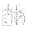
その課題を解決する一つの方法として、例えば特開2000−188703号公報に開示されているものがあり、その構成を図5に示す。図5において、101はビデオカメラ、102はCCU(カメラコントロールユニット)、110は撮像デバイス、111はA/D変換回路、112はメモリー、113はプロセスLSI、120はプロセスLSI、121はメモリー、122は切替回路、123は伝送路である。 One method for solving this problem is disclosed in, for example, Japanese Patent Laid-Open No. 2000-188703, and the configuration is shown in FIG. In FIG. 5, 101 is a video camera, 102 is a CCU (camera control unit), 110 is an imaging device, 111 is an A / D conversion circuit, 112 is a memory, 113 is a process LSI, 120 is a process LSI, 121 is a memory, 122 Is a switching circuit, and 123 is a transmission line.
以上のように構成された従来の撮像装置について、以下その動作について3倍速度撮影を例として説明する。 Regarding the conventional imaging apparatus configured as described above, the operation thereof will be described below using triple-speed shooting as an example.
まず、ビデオカメラ101において、撮像デバイス110により標準の3倍で高速度撮影したビデオ信号SOを、A/D変換回路111によりアナログのビデオ信号をディジタルのビデオ信号に変換し、メモリー112により標準速度の3本のビデオ信号SO1〜SO3に分離し、この3本の標準ビデオ信号SO1〜SO3をプロセスLSI113により所定伝送形式の標準ビデオ信号S1〜S3に変換して広帯域の伝送路123を介してカメラコントロールユニット102に伝送する。
First, in the
ここで、3倍速度以下の高速度撮影映像SOを複数本の標準ビデオ信号SO1〜SO3に分離する際に、ブランクフィールドを含ませるようにしている。ブランクフィールド信号Sbfは複数本の標準ビデオ信号SO1〜SO3のどのフィールドにブランクフィールドが含まれているかを示す。ブランクフィールド信号Sbfも同様に伝送路123を介してカメラコントロールユニット102に伝送する。
Here, a blank field is included when separating a high-speed captured video SO of 3 times speed or less into a plurality of standard video signals SO1 to SO3. The blank field signal Sbf indicates which field of the plurality of standard video signals SO1 to SO3 includes the blank field. Similarly, the blank field signal Sbf is transmitted to the
カメラコントロールユニット102において、伝送路123を介して伝送された3本の標準ビデオ信号SO1〜SO3をプロセスLSI120により内部処理可能な3本の標準ビデオ信号SU1〜SU3に変換し、切替回路122により3本の標準速度ビデオ信号を単位期間毎に揃えて複数本のSDI出力SI1〜SI3として各種映像機器へ出力する。
In the
ここで、メモリー121によりブランクフィールド信号Sbfからブランクフィールドを判別して3本の標準ビデオ信号SU1〜SU3から有効な映像のみを蓄積し、メモリー121からスロー再生信号SLを出力する。
Here, the
なお、ビデオカメラ101において、3倍速の高速度映像SOをメモリー121を使用して3本の標準ビデオ信号SO1〜SO3にした後に、プロセスLSI113に3本の標準ビデオ信号SO1〜SO3を入力している。ここで、プロセスLSI113はカメラ特有のビデオ信号を処理する機能と伝送用フォーマットに変換する伝送プロセス機能とを有する。なお、図5においては、プロセスLSI113は単一で示されているが、ビデオ信号処理と伝送用処理を別々のICで構成しても良いし、また、3本の標準ビデオ信号SO1〜SO3に対して3個のICで構成してビデオ信号処理をしても良く、この場合には、従来の標準カメラのプロセス用のICをそのまま流用して回路を構成することができる。
In the
伝送用フォーマット変換プロセスICでは3本の標準カメラ内部処理用のディジタルビデオ信号を標準規格である4:2:2の輝度信号および色差信号Y,CB,CR,伝送周波数27MHz,ビット数10ビットのパラレル信号で構成されるD1フォーマット信号相当のフォーマットに変換する。そして、その後、光ファイバーやTRIAX等の伝送路123を介して信号線、電源線、制御線を伝送するため、3本のビデオ信号の時分割多重化処理をする。または、これに限らず、3本の270MHzのシリアルのSDI信号相当として3本のBNCケーブルを用いて伝送することも可能である。
しかしながら上記のような技術においては、高速撮影においてカメラヘッドから3倍速に相当する3倍の信号データを伝送するために、カメラコントロールユニットとの伝送においては、3本のビデオ信号の時分割多重化処理を行うか、3本のBNCケーブルを用意する必要がある。また、スロー再生するためには、カメラコントロールユニットに例えば3台のVTRを接続し同期運転する必要がある、という課題を有している。 However, in the technique as described above, since 3 times signal data corresponding to 3 times speed is transmitted from the camera head in high-speed shooting, time division multiplexing of 3 video signals is performed in transmission with the camera control unit. It is necessary to perform processing or to prepare three BNC cables. Further, in order to perform slow playback, there is a problem that it is necessary to connect, for example, three VTRs to the camera control unit and perform synchronous operation.
本発明は、上述の従来の課題を解決するもので、高速撮像装置において特殊な伝送装置や特殊な外部記録装置を必要とせずに、スローモーション再生画像を得ることを目的とする。 The present invention solves the above-described conventional problems, and an object thereof is to obtain a slow motion reproduced image without requiring a special transmission device or a special external recording device in a high-speed imaging device.
本発明の請求項1に記載の発明は、第1の周期で被写体を撮像する撮像手段と、前記撮像手段で撮像された映像信号を圧縮する圧縮手段と、前記圧縮手段で圧縮された映像信号を格納する記憶手段と、前記記憶手段に格納された映像信号データを第2の周期で読み出して伸張して出力する伸張手段とを備え、前記第2の周期は前記第1の周期より長いことを特徴としたものであり、特殊な外部記録装置を必要とせずに撮像装置よりスロー再生信号を得るという作用を有する。
The invention according to
本発明の請求項2に記載の発明は、前記撮像手段で撮像された第1の周期の映像信号を第2の周期の映像信号に変換する変換手段と、前記伸張手段と前記変換手段の信号を切り替える選択手段とを備えることを特徴としたものであり、スロー再生のための高速撮像信号をメモリに記録すると同時に通常速の映像信号を出力する事が可能という作用を有する。 According to a second aspect of the present invention, there is provided a conversion means for converting a video signal of the first period imaged by the imaging means into a video signal of the second period, a signal of the expansion means and the conversion means. And a selection means for switching between them, and has a function of recording a high-speed image signal for slow reproduction in a memory and simultaneously outputting a normal-speed video signal.
本発明の請求項3に記載の発明は、前記撮像手段で撮像された第1の周期の映像信号を第2の周期の映像信号に変換する変換手段を備え、前記伸張手段の出力信号と前記変換手段の出力信号を共に出力することを特徴としたものであり、スロー再生が可能という特徴を有しつつも常に通常速の映像信号を出力できるという作用を有する。
The invention according to
本発明の請求項4に記載の発明は、前記変換手段は、前記撮像手段で撮像された第1の周期の映像信号から一部の映像信号を第2の周期として出力することを特徴としたものであり、フィールド間引きという簡便な方法にて通常速の映像信号を得ることができるという作用を有する。 The invention according to claim 4 of the present invention is characterized in that the conversion means outputs a part of the video signal as the second period from the video signal of the first period imaged by the imaging means. Therefore, it has an effect that a normal-speed video signal can be obtained by a simple method called field thinning.
本発明の請求項5に記載の発明は、前記変換手段は、前記撮像手段で撮像された第1の周期の複数の映像信号に加算演算を施して、第2の周期の映像信号として出力することを特徴としたものであり、高速撮影時の通常速映像信号としてノイズの少ない信号を得ることができるという作用を有する。 According to a fifth aspect of the present invention, the conversion unit performs addition operation on the plurality of video signals having the first cycle imaged by the imaging unit and outputs the result as a video signal having the second cycle. This is characterized in that a signal with less noise can be obtained as a normal-speed video signal during high-speed shooting.
本発明の請求項6に記載の発明は、前記記憶手段は半導体メモリであることを特徴としたものであり、高速撮像などの可変速度のデータ記録が容易という作用を有する。
The invention according to
本発明の請求項7に記載の発明は、前記記憶手段は取り外し可能な不揮発性メモリであることを特徴としたものであり、高速撮像信号を格納したメモリを他の再生機器に接続することにより、信号伝送を必要とせずに簡単にスロー再生する事ができるという作用を有する。 The invention according to claim 7 of the present invention is characterized in that the storage means is a removable non-volatile memory, and a memory storing a high-speed imaging signal is connected to another playback device. , It has the effect of being able to easily perform slow reproduction without requiring signal transmission.
本発明の請求項8に記載の発明は、前記第1の周期と前記第2の周期が整数比であることを特徴としたものであり、メモリ制御が簡便になるという作用を有する。 The invention according to claim 8 of the present invention is characterized in that the first period and the second period are an integer ratio, and has an effect that memory control is simplified.
以上のように本発明によれば、高速撮像装置において特殊な伝送装置や特殊な外部記録装置を必要とせずに、スローモーション再生画像を得ることができるという優れた効果が得られる。 As described above, according to the present invention, it is possible to obtain an excellent effect that a slow motion playback image can be obtained without requiring a special transmission device or a special external recording device in a high-speed imaging device.
以下、本発明の実施の形態について、図面を用いて説明する。 Hereinafter, embodiments of the present invention will be described with reference to the drawings.
(実施の形態1)
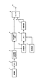
図1は本発明の実施の形態1における撮像装置の構成を示すブロック図である。
(Embodiment 1)
FIG. 1 is a block diagram showing a configuration of an imaging apparatus according to
図1において、1は撮像部、2はA/D変換器、3はカメラ信号処理回路、4は速度変換回路、5は圧縮回路、6はメモリ、7は伸張回路、8は制御回路、9はセレクタ、10は出力端子である。 In FIG. 1, 1 is an imaging unit, 2 is an A / D converter, 3 is a camera signal processing circuit, 4 is a speed conversion circuit, 5 is a compression circuit, 6 is a memory, 7 is a decompression circuit, 8 is a control circuit, 9 Is a selector and 10 is an output terminal.
以上のように構成された実施の形態1による撮像装置の動作について、例えばスローモーション映像の速度比が1/3、すなわち3倍速の高速撮像を行う場合を、以下に図1および図2を適宜参照し説明する。 As for the operation of the imaging apparatus according to the first embodiment configured as described above, for example, in the case of performing high-speed imaging with a speed ratio of slow motion video of 1/3, that is, triple speed, FIG. 1 and FIG. Refer to and explain.
図1において、撮像部1、A/D変換器2、カメラ信号処理回路3は、通常のカメラの構成要素であり、その動作も基本的には同じである。すなわち、撮像部1は光学的な画像信号を電気信号に変換し出力するもので、例えばCCD(Charge Coupled Device)型撮像素子とその駆動回路、およびアナログ信号処理回路からなる。A/D変換器2は、撮像部1の出力であるアナログ映像信号をディジタル映像信号に変換し、カメラ信号処理回路3へと入力する。カメラ信号処理回路3では、オフセット調整、ゲイン調整、ガンマ補正、輪郭補正など、通常のカメラとして必要な信号処理が行われ、その出力信号は記録、表示可能な標準形態の映像信号となる。
In FIG. 1, an
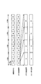
ここで、3倍速の高速撮像を行うので、通常の毎秒60フィールドの映像信号に対して、180フィールドの映像信号を生成することが必要となる。そこで、撮像部1では、撮像素子から通常の3倍の速度で信号電荷を取り出し、図2に示すように通常の1/3の時間である1/180秒毎に、1A、1B、1C、2A、2B、という具合に映像信号が出力される。この撮像信号に対して、A/D変換器2、およびカメラ信号処理回路3も通常の3倍速で動作を行う。
Here, since high-speed imaging at 3 × speed is performed, it is necessary to generate a video signal of 180 fields for a normal video signal of 60 fields per second. Therefore, the
カメラ信号処理回路3の出力である3倍速の映像信号は、圧縮回路5においてデータ圧縮が行われる。これは、例えばブロック化・DCT(離散コサイン変換)・量子化といった処理によりデータ量を削減するものである。この圧縮された映像データは、メモリ6に記録されるが、その記録動作は制御回路8により制御され、通常の3倍速で記録される。すなわち、図2に示すように、1/180秒毎に1フィールド分の映像データが記録される。なお、メモリ6はフラッシュメモリのような不揮発性メモリや、あるいはSDRAMのような揮発性メモリでも構わない。
The 3 × speed video signal that is the output of the camera
次に、スロー再生時の動作を以下に説明する。再生時には、制御回路8がメモリ6を読み出し制御し、通常の映像信号と同じ毎秒60フィールドの割合でデータを出力する。その出力データは、伸張回路7においてIDCT(逆離散コサイン変換)などデータ圧縮とは逆の処理を施され、映像信号の形態に戻される。すなわち、図2に示すように、通常と同じ1/60秒毎に、1A、1B、1C、2A、2B、という具合に映像信号が出力されるので、撮影時と比較して時間軸を3倍に拡大した映像信号が得られる。
Next, the operation during slow playback will be described below. At the time of reproduction, the control circuit 8 reads and controls the
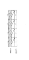
なお、3倍速の高速撮像時においては、カメラ信号処理回路3の出力の3倍速映像信号は、上述したようなメモリ6への記録と同時に、速度変換回路4へ入力され、通常速度の映像信号に変換される。その変換する簡単な方法としては、図3に示すように、180フィールドの映像信号から、3フィールドから1フィールドの割合で映像信号を抜き出す事により、60フィールドの映像信号を生成する事である。
At the time of high-speed imaging at 3 × speed, the 3 × speed video signal output from the camera
そして、セレクタ9は出力端子10へ出力する映像信号を選択するもので、高速撮像時にはa側の信号を、スロー再生時にはb側の信号を選択する。すわなち、高速撮像時には3倍速の映像信号をメモリ6に記録すると同時に、通常速に変換した映像信号を出力して、通常のカメラと同様の使い方をすることができる。また、再生時には、メモリ6に記録された映像信号を、記録時と比較して1/3の速度で再生することにより、スロー再生信号を得ることができる。
The selector 9 selects the video signal to be output to the
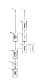
また、図4には別の構成を示すブロック図を示す。図4に示す撮像装置の構成は、図1に示した構成とほとんど同様であるが、セレクタ9が省略され、出力端子11が追加している点が異なる。その他の構成要素およびその動作は図1と同様である。 FIG. 4 is a block diagram showing another configuration. The configuration of the imaging apparatus shown in FIG. 4 is almost the same as the configuration shown in FIG. 1 except that the selector 9 is omitted and an output terminal 11 is added. Other components and their operations are the same as in FIG.
図4に示す構成の撮像装置では、出力端子10からは常に通常速度の映像信号を出力し、出力端子11からはスロー再生時の映像信号を出力する事を特徴とする。そこで、出力端子10の映像信号を使用する事により、常に通常の撮像装置として使用する事が可能となる。なお、スロー再生信号が必要な時には、出力端子11の信号を使用すればよい。すなわち、図4に示す構成を用いる事により、通常速の映像信号とスロー再生の信号の双方が必要となる場合にも対応できる。
The image pickup apparatus having the configuration shown in FIG. 4 is characterized in that a normal-speed video signal is always output from the
なお、速度変換回路4として、簡便なフィールドを間引きする方法を述べたが、通常の映像信号と比較すると撮像素子における蓄積時間が短いので、S/Nが悪くなる。そこで、速度変換回路4として、例えば複数のフィールドから加算演算する構成とする事により、S/Nの良い映像信号を得ることができる。 Although a method for thinning out a simple field has been described as the speed conversion circuit 4, the S / N is deteriorated because the accumulation time in the image sensor is short compared to a normal video signal. Therefore, by adopting a configuration in which the speed conversion circuit 4 performs an addition operation from a plurality of fields, for example, a video signal with a good S / N can be obtained.
また、メモリ6として半導体メモリを使用する事により、高速撮像時のような通常時とは異なる信号データレートのデータ記録を容易にする事ができる。
Further, by using a semiconductor memory as the
なお、本実施の形態のように、高速撮像時が通常撮像時の整数倍のフィールドレートである場合が制御が簡単となるが、整数倍に限定するものではない。 As in the present embodiment, control is simple when the field rate at the time of high-speed imaging is an integer multiple of that at the time of normal imaging, but is not limited to an integer multiple.
さらに、撮像部の撮像デバイスとしてはCCDに限定するものではなく、例えばディジタル信号を出力するCMOS型撮像素子でも同様の効果を実現することができる。 Furthermore, the image pickup device of the image pickup unit is not limited to the CCD, and the same effect can be realized even with, for example, a CMOS image pickup device that outputs a digital signal.
本発明にかかる撮像装置は、美しいスローモーション再生を実現できる高速撮像装置として有用である。 The imaging apparatus according to the present invention is useful as a high-speed imaging apparatus capable of realizing beautiful slow motion reproduction.
1 撮像部
2 A/D変換器
3 カメラ信号処理回路
4 速度変換回路
5 圧縮回路
5 メモリ
7 伸張回路
8 制御回路
9 セレクタ
10 出力端子
11 出力端子
DESCRIPTION OF
Claims (8)
前記撮像手段で撮像された映像信号を圧縮する圧縮手段と、
前記圧縮手段で圧縮された映像信号を格納する記憶手段と、
前記記憶手段に格納された映像信号データを第2の周期で読み出して伸張して出力する伸張手段と、を備え、
前記第2の周期は前記第1の周期より長いことを特徴とする撮像装置。 Imaging means for imaging a subject in a first period;
Compression means for compressing the video signal imaged by the imaging means;
Storage means for storing the video signal compressed by the compression means;
Decompression means that reads out the video signal data stored in the storage means in a second period, decompresses and outputs the data,
The imaging apparatus, wherein the second period is longer than the first period.
前記伸張手段と前記変換手段の信号を切り替える選択手段とを備えることを特徴とする請求項1記載の撮像装置。 Conversion means for converting a video signal of the first period imaged by the imaging means into a video signal of the second period;
The imaging apparatus according to claim 1, further comprising a selection unit that switches a signal of the expansion unit and the conversion unit.
前記伸張手段の出力信号と前記変換手段の出力信号を共に出力することを特徴とする請求項1記載の撮像装置。 Conversion means for converting a video signal of the first period imaged by the imaging means into a video signal of the second period;
2. The imaging apparatus according to claim 1, wherein an output signal of the expansion unit and an output signal of the conversion unit are output together.
The imaging apparatus according to claim 1, wherein the first period and the second period are an integer ratio.
Priority Applications (1)
| Application Number | Priority Date | Filing Date | Title |
|---|---|---|---|
| JP2004110784A JP2005295423A (en) | 2004-04-05 | 2004-04-05 | Imaging device |
Applications Claiming Priority (1)
| Application Number | Priority Date | Filing Date | Title |
|---|---|---|---|
| JP2004110784A JP2005295423A (en) | 2004-04-05 | 2004-04-05 | Imaging device |
Publications (1)
| Publication Number | Publication Date |
|---|---|
| JP2005295423A true JP2005295423A (en) | 2005-10-20 |
Family
ID=35327832
Family Applications (1)
| Application Number | Title | Priority Date | Filing Date |
|---|---|---|---|
| JP2004110784A Pending JP2005295423A (en) | 2004-04-05 | 2004-04-05 | Imaging device |
Country Status (1)
| Country | Link |
|---|---|
| JP (1) | JP2005295423A (en) |
Cited By (6)
| Publication number | Priority date | Publication date | Assignee | Title |
|---|---|---|---|---|
| WO2008053716A1 (en) | 2006-10-30 | 2008-05-08 | Sony Corporation | Imaging device and imaging method |
| WO2008056606A1 (en) * | 2006-11-07 | 2008-05-15 | Panasonic Corporation | Imaging device |
| WO2008075688A1 (en) | 2006-12-18 | 2008-06-26 | Sony Corporation | Imaging device and method, recording device and method, and reproduction device and method |
| EP2064875A2 (en) * | 2006-09-20 | 2009-06-03 | Casio Computer Co., Ltd. | Image pickup device and image display control method |
| US8903222B2 (en) | 2007-02-01 | 2014-12-02 | Sony Corporation | Image reproducing apparatus, image reproducing method, image capturing apparatus, and control method therefor |
| CN105323556A (en) * | 2015-11-11 | 2016-02-10 | 深圳市阿格斯科技有限公司 | Multichannel image transmission method and device for surveillance camera |
-
2004
- 2004-04-05 JP JP2004110784A patent/JP2005295423A/en active Pending
Cited By (23)
| Publication number | Priority date | Publication date | Assignee | Title |
|---|---|---|---|---|
| EP2064875A2 (en) * | 2006-09-20 | 2009-06-03 | Casio Computer Co., Ltd. | Image pickup device and image display control method |
| US8849090B2 (en) | 2006-10-30 | 2014-09-30 | Sony Corporation | High speed image capturing apparatus and method |
| US10708563B2 (en) | 2006-10-30 | 2020-07-07 | Sony Corporation | Image capturing apparatus and image capturing method |
| US11388380B2 (en) | 2006-10-30 | 2022-07-12 | Sony Corporation | Image capturing apparatus and image capturing method |
| EP2169947A1 (en) * | 2006-10-30 | 2010-03-31 | Sony Corporation | Imaging device and imaging method |
| EP2169947A4 (en) * | 2006-10-30 | 2011-04-06 | Sony Corp | Imaging device and imaging method |
| EP2398228A1 (en) * | 2006-10-30 | 2011-12-21 | Sony Corporation | High speed image capturing apparatus and method |
| US10986323B2 (en) | 2006-10-30 | 2021-04-20 | Sony Corporation | Image capturing apparatus and image capturing method |
| US9661291B2 (en) | 2006-10-30 | 2017-05-23 | Sony Corporation | Image capturing apparatus and image capturing method |
| US9025929B2 (en) | 2006-10-30 | 2015-05-05 | Sony Corporation | Image capturing apparatus and image capturing method |
| WO2008053716A1 (en) | 2006-10-30 | 2008-05-08 | Sony Corporation | Imaging device and imaging method |
| US11750937B2 (en) | 2006-10-30 | 2023-09-05 | Sony Group Corporation | Image capturing apparatus and image capturing method |
| US10313648B2 (en) | 2006-10-30 | 2019-06-04 | Sony Corporation | Image capturing apparatus and image capturing method |
| KR101395433B1 (en) * | 2006-10-30 | 2014-05-14 | 소니 주식회사 | Imaging device and imaging method |
| US9866811B2 (en) | 2006-10-30 | 2018-01-09 | Sony Corporation | Image capturing apparatus and image capturing method |
| US9538153B1 (en) | 2006-10-30 | 2017-01-03 | Sony Corporation | Image capturing apparatus and image capturing method |
| WO2008056606A1 (en) * | 2006-11-07 | 2008-05-15 | Panasonic Corporation | Imaging device |
| JP5084741B2 (en) * | 2006-11-07 | 2012-11-28 | パナソニック株式会社 | Imaging device |
| US8958682B2 (en) | 2006-11-07 | 2015-02-17 | Panasonic Intellectual Property Management Co., Ltd. | Imaging device |
| WO2008075688A1 (en) | 2006-12-18 | 2008-06-26 | Sony Corporation | Imaging device and method, recording device and method, and reproduction device and method |
| US8102436B2 (en) | 2006-12-18 | 2012-01-24 | Sony Corporation | Image-capturing apparatus and method, recording apparatus and method, and reproducing apparatus and method |
| US8903222B2 (en) | 2007-02-01 | 2014-12-02 | Sony Corporation | Image reproducing apparatus, image reproducing method, image capturing apparatus, and control method therefor |
| CN105323556A (en) * | 2015-11-11 | 2016-02-10 | 深圳市阿格斯科技有限公司 | Multichannel image transmission method and device for surveillance camera |
Similar Documents
| Publication | Publication Date | Title |
|---|---|---|
| JP5036410B2 (en) | Imaging apparatus and control method thereof | |
| KR101395433B1 (en) | Imaging device and imaging method | |
| US7667737B2 (en) | Video signal processing apparatus for generating a video signal from output of a solid-state imaging element and digital camera including the same | |
| JP5092983B2 (en) | Movie playback device, imaging device, and program | |
| US7535495B2 (en) | Digital camera, control method thereof and portable terminal | |
| KR20070050822A (en) | Imaging device, and image processing method, and program | |
| JP2007097033A (en) | Imaging apparatus and program therefor | |
| JP4178634B2 (en) | Video signal transmission apparatus, video signal transmission method, video signal imaging apparatus, and video signal processing apparatus | |
| US8564685B2 (en) | Video signal capturing apparatus, signal processing and control apparatus, and video signal capturing, video signal processing, and transferring system and method | |
| US7705896B2 (en) | Imaging apparatus which adds a first number of R and B pixels, and adds a second number of G pixels | |
| US20240031582A1 (en) | Video compression apparatus, electronic apparatus, and video compression program | |
| JP2009194770A (en) | Imaging device, moving image reproducing apparatus, and program thereof | |
| JP2005295423A (en) | Imaging device | |
| US20050057667A1 (en) | Image pickup apparatus having moving picture photographing function and moving picture photographing method thereof | |
| KR20090064278A (en) | Recording apparatus, replaying apparatus, recording method, replaying method and program recording medium | |
| JP2005217955A (en) | Imaging device, its control method, program, and storage medium | |
| JP4227596B2 (en) | Pulse generation circuit, imaging device and camera | |
| US20050089313A1 (en) | Recording and play reproducing device | |
| US20100149375A1 (en) | Apparatus and method for faster recording and reproduction of digital video images | |
| JP7156367B2 (en) | Video compression device, decompression device, electronic device, video compression program, and decompression program | |
| KR20090071321A (en) | Imaging apparatus, imaging method and storing medium having computer program to perform the same | |
| JP2005192096A (en) | Image pickup device, method for recording video file, and program | |
| JP3811668B2 (en) | Video imaging device and video conversion device | |
| JP4199391B2 (en) | Solid-state imaging device and signal readout method | |
| KR100818027B1 (en) | Imaging apparatus and imaging method |
Legal Events
| Date | Code | Title | Description |
|---|---|---|---|
| A977 | Report on retrieval |
Free format text: JAPANESE INTERMEDIATE CODE: A971007 Effective date: 20070524 |
|
| A131 | Notification of reasons for refusal |
Free format text: JAPANESE INTERMEDIATE CODE: A131 Effective date: 20070529 |
|
| A521 | Request for written amendment filed |
Free format text: JAPANESE INTERMEDIATE CODE: A523 Effective date: 20070711 |
|
| A02 | Decision of refusal |
Free format text: JAPANESE INTERMEDIATE CODE: A02 Effective date: 20071016 |