JP2005294065A - Fuel cell unit, information processing apparatus, and power supply control method thereof - Google Patents
Fuel cell unit, information processing apparatus, and power supply control method thereof Download PDFInfo
- Publication number
- JP2005294065A JP2005294065A JP2004108045A JP2004108045A JP2005294065A JP 2005294065 A JP2005294065 A JP 2005294065A JP 2004108045 A JP2004108045 A JP 2004108045A JP 2004108045 A JP2004108045 A JP 2004108045A JP 2005294065 A JP2005294065 A JP 2005294065A
- Authority
- JP
- Japan
- Prior art keywords
- power generation
- unit
- information processing
- fuel cell
- power
- Prior art date
- Legal status (The legal status is an assumption and is not a legal conclusion. Google has not performed a legal analysis and makes no representation as to the accuracy of the status listed.)
- Withdrawn
Links
Images
Classifications
-
- G—PHYSICS
- G06—COMPUTING; CALCULATING OR COUNTING
- G06F—ELECTRIC DIGITAL DATA PROCESSING
- G06F1/00—Details not covered by groups G06F3/00 - G06F13/00 and G06F21/00
- G06F1/16—Constructional details or arrangements
- G06F1/1613—Constructional details or arrangements for portable computers
- G06F1/1632—External expansion units, e.g. docking stations
-
- G—PHYSICS
- G06—COMPUTING; CALCULATING OR COUNTING
- G06F—ELECTRIC DIGITAL DATA PROCESSING
- G06F1/00—Details not covered by groups G06F3/00 - G06F13/00 and G06F21/00
- G06F1/26—Power supply means, e.g. regulation thereof
-
- H—ELECTRICITY
- H01—ELECTRIC ELEMENTS
- H01M—PROCESSES OR MEANS, e.g. BATTERIES, FOR THE DIRECT CONVERSION OF CHEMICAL ENERGY INTO ELECTRICAL ENERGY
- H01M8/00—Fuel cells; Manufacture thereof
- H01M8/04—Auxiliary arrangements, e.g. for control of pressure or for circulation of fluids
- H01M8/04082—Arrangements for control of reactant parameters, e.g. pressure or concentration
- H01M8/04186—Arrangements for control of reactant parameters, e.g. pressure or concentration of liquid-charged or electrolyte-charged reactants
-
- H—ELECTRICITY
- H01—ELECTRIC ELEMENTS
- H01M—PROCESSES OR MEANS, e.g. BATTERIES, FOR THE DIRECT CONVERSION OF CHEMICAL ENERGY INTO ELECTRICAL ENERGY
- H01M8/00—Fuel cells; Manufacture thereof
- H01M8/04—Auxiliary arrangements, e.g. for control of pressure or for circulation of fluids
- H01M8/04298—Processes for controlling fuel cells or fuel cell systems
- H01M8/04313—Processes for controlling fuel cells or fuel cell systems characterised by the detection or assessment of variables; characterised by the detection or assessment of failure or abnormal function
- H01M8/0432—Temperature; Ambient temperature
- H01M8/04328—Temperature; Ambient temperature of anode reactants at the inlet or inside the fuel cell
-
- H—ELECTRICITY
- H01—ELECTRIC ELEMENTS
- H01M—PROCESSES OR MEANS, e.g. BATTERIES, FOR THE DIRECT CONVERSION OF CHEMICAL ENERGY INTO ELECTRICAL ENERGY
- H01M8/00—Fuel cells; Manufacture thereof
- H01M8/04—Auxiliary arrangements, e.g. for control of pressure or for circulation of fluids
- H01M8/04298—Processes for controlling fuel cells or fuel cell systems
- H01M8/04313—Processes for controlling fuel cells or fuel cell systems characterised by the detection or assessment of variables; characterised by the detection or assessment of failure or abnormal function
- H01M8/0444—Concentration; Density
- H01M8/04447—Concentration; Density of anode reactants at the inlet or inside the fuel cell
-
- H—ELECTRICITY
- H01—ELECTRIC ELEMENTS
- H01M—PROCESSES OR MEANS, e.g. BATTERIES, FOR THE DIRECT CONVERSION OF CHEMICAL ENERGY INTO ELECTRICAL ENERGY
- H01M8/00—Fuel cells; Manufacture thereof
- H01M8/04—Auxiliary arrangements, e.g. for control of pressure or for circulation of fluids
- H01M8/04298—Processes for controlling fuel cells or fuel cell systems
- H01M8/04313—Processes for controlling fuel cells or fuel cell systems characterised by the detection or assessment of variables; characterised by the detection or assessment of failure or abnormal function
- H01M8/04537—Electric variables
- H01M8/04544—Voltage
- H01M8/04559—Voltage of fuel cell stacks
-
- H—ELECTRICITY
- H01—ELECTRIC ELEMENTS
- H01M—PROCESSES OR MEANS, e.g. BATTERIES, FOR THE DIRECT CONVERSION OF CHEMICAL ENERGY INTO ELECTRICAL ENERGY
- H01M8/00—Fuel cells; Manufacture thereof
- H01M8/04—Auxiliary arrangements, e.g. for control of pressure or for circulation of fluids
- H01M8/04298—Processes for controlling fuel cells or fuel cell systems
- H01M8/04694—Processes for controlling fuel cells or fuel cell systems characterised by variables to be controlled
- H01M8/04746—Pressure; Flow
- H01M8/04753—Pressure; Flow of fuel cell reactants
-
- H—ELECTRICITY
- H01—ELECTRIC ELEMENTS
- H01M—PROCESSES OR MEANS, e.g. BATTERIES, FOR THE DIRECT CONVERSION OF CHEMICAL ENERGY INTO ELECTRICAL ENERGY
- H01M8/00—Fuel cells; Manufacture thereof
- H01M8/04—Auxiliary arrangements, e.g. for control of pressure or for circulation of fluids
- H01M8/04298—Processes for controlling fuel cells or fuel cell systems
- H01M8/04694—Processes for controlling fuel cells or fuel cell systems characterised by variables to be controlled
- H01M8/04791—Concentration; Density
- H01M8/04798—Concentration; Density of fuel cell reactants
-
- H—ELECTRICITY
- H01—ELECTRIC ELEMENTS
- H01M—PROCESSES OR MEANS, e.g. BATTERIES, FOR THE DIRECT CONVERSION OF CHEMICAL ENERGY INTO ELECTRICAL ENERGY
- H01M8/00—Fuel cells; Manufacture thereof
- H01M8/04—Auxiliary arrangements, e.g. for control of pressure or for circulation of fluids
- H01M8/04298—Processes for controlling fuel cells or fuel cell systems
- H01M8/04694—Processes for controlling fuel cells or fuel cell systems characterised by variables to be controlled
- H01M8/04955—Shut-off or shut-down of fuel cells
-
- H—ELECTRICITY
- H01—ELECTRIC ELEMENTS
- H01M—PROCESSES OR MEANS, e.g. BATTERIES, FOR THE DIRECT CONVERSION OF CHEMICAL ENERGY INTO ELECTRICAL ENERGY
- H01M2250/00—Fuel cells for particular applications; Specific features of fuel cell system
- H01M2250/30—Fuel cells in portable systems, e.g. mobile phone, laptop
-
- H—ELECTRICITY
- H01—ELECTRIC ELEMENTS
- H01M—PROCESSES OR MEANS, e.g. BATTERIES, FOR THE DIRECT CONVERSION OF CHEMICAL ENERGY INTO ELECTRICAL ENERGY
- H01M8/00—Fuel cells; Manufacture thereof
- H01M8/10—Fuel cells with solid electrolytes
- H01M8/1009—Fuel cells with solid electrolytes with one of the reactants being liquid, solid or liquid-charged
- H01M8/1011—Direct alcohol fuel cells [DAFC], e.g. direct methanol fuel cells [DMFC]
-
- Y—GENERAL TAGGING OF NEW TECHNOLOGICAL DEVELOPMENTS; GENERAL TAGGING OF CROSS-SECTIONAL TECHNOLOGIES SPANNING OVER SEVERAL SECTIONS OF THE IPC; TECHNICAL SUBJECTS COVERED BY FORMER USPC CROSS-REFERENCE ART COLLECTIONS [XRACs] AND DIGESTS
- Y02—TECHNOLOGIES OR APPLICATIONS FOR MITIGATION OR ADAPTATION AGAINST CLIMATE CHANGE
- Y02B—CLIMATE CHANGE MITIGATION TECHNOLOGIES RELATED TO BUILDINGS, e.g. HOUSING, HOUSE APPLIANCES OR RELATED END-USER APPLICATIONS
- Y02B90/00—Enabling technologies or technologies with a potential or indirect contribution to GHG emissions mitigation
- Y02B90/10—Applications of fuel cells in buildings
-
- Y—GENERAL TAGGING OF NEW TECHNOLOGICAL DEVELOPMENTS; GENERAL TAGGING OF CROSS-SECTIONAL TECHNOLOGIES SPANNING OVER SEVERAL SECTIONS OF THE IPC; TECHNICAL SUBJECTS COVERED BY FORMER USPC CROSS-REFERENCE ART COLLECTIONS [XRACs] AND DIGESTS
- Y02—TECHNOLOGIES OR APPLICATIONS FOR MITIGATION OR ADAPTATION AGAINST CLIMATE CHANGE
- Y02E—REDUCTION OF GREENHOUSE GAS [GHG] EMISSIONS, RELATED TO ENERGY GENERATION, TRANSMISSION OR DISTRIBUTION
- Y02E60/00—Enabling technologies; Technologies with a potential or indirect contribution to GHG emissions mitigation
- Y02E60/30—Hydrogen technology
- Y02E60/50—Fuel cells
Landscapes
- Engineering & Computer Science (AREA)
- General Chemical & Material Sciences (AREA)
- Sustainable Development (AREA)
- Sustainable Energy (AREA)
- Chemical & Material Sciences (AREA)
- Chemical Kinetics & Catalysis (AREA)
- Manufacturing & Machinery (AREA)
- Life Sciences & Earth Sciences (AREA)
- Electrochemistry (AREA)
- Theoretical Computer Science (AREA)
- Physics & Mathematics (AREA)
- General Physics & Mathematics (AREA)
- General Engineering & Computer Science (AREA)
- Computer Hardware Design (AREA)
- Human Computer Interaction (AREA)
- Fuel Cell (AREA)
Abstract
Description
本発明は、情報処理装置に接続される燃料電池ユニット、燃料電池ユニットを備えた情報処理装置および燃料電池ユニットを備えた情報処理装置の電源制御方法に関する。 The present invention relates to a fuel cell unit connected to an information processing device, an information processing device including the fuel cell unit, and a power control method for the information processing device including the fuel cell unit.
現在、情報処理装置への電源供給源の一つである二次電池として例えばリチウムイオン電池が使用されている。二次電池の有する特徴の一つは、使い捨てタイプである一次電池と比較して、例えば商用電源を用いて充電することで繰り返し使用可能な点にある。 Currently, for example, a lithium ion battery is used as a secondary battery which is one of the power supply sources to the information processing apparatus. One of the characteristics of a secondary battery is that it can be used repeatedly by charging it with a commercial power source, for example, as compared with a disposable primary battery.
一方で、リチウムイオン電池は二次電池であるため、例えば商用電源を用いて充電する必要がある。 On the other hand, since a lithium ion battery is a secondary battery, it needs to be charged using, for example, a commercial power source.
また、近年における情報処理装置の機能性能の向上は著しく、これに伴って該情報処理装置の消費電力は増加の傾向にある。そこで、情報処理装置に電力を供給するリチウムイオン電池が提供するエネルギの密度、即ち単位体積或いは単位質量あたりの出力エネルギ量を向上が図られているものの、顕著な向上を望むのは難しい状況にある。 In recent years, the functional performance of the information processing apparatus has been remarkably improved, and the power consumption of the information processing apparatus tends to increase accordingly. Therefore, although the energy density provided by the lithium ion battery that supplies power to the information processing apparatus, that is, the output energy amount per unit volume or unit mass is improved, it is difficult to expect a significant improvement. is there.
一方、燃料電池のエネルギ密度は、理論的にはリチウムイオン電池の10倍とも言われている(例えば、非特許文献1参照)。これは、燃料電池がリチウムイオン電池に対して、体積或いは質量が同じとすると、より長時間(例えば10倍)の電力供給が可能となる潜在的能力を有していることを意味する。また、両者の電力供給時間を等しいとするならば、燃料電池の方がリチウムイオン電池に対して小型・軽量化が可能となる潜在的能力を有している事を意味する。
On the other hand, the energy density of a fuel cell is theoretically said to be 10 times that of a lithium ion battery (see Non-Patent
また、燃料電池は、燃料、例えばメタノール等を小型の容器に封入してユニット化し、小型の容器ごと交換して使用すれば、外部からの充電を必要としない。従って、例えばAC電源設備の無い場所において、リチウムイオン電池を使用して電力を確保する場合と比較して燃料電池を使用して電力を確保する場合の方が、より長時間にわたって情報処理装置を使用可能である。 Further, the fuel cell does not require charging from the outside if the fuel cell, for example, methanol, is enclosed in a small container to form a unit and the small container is replaced and used. Therefore, for example, in a place where there is no AC power supply facility, the information processing apparatus is used for a longer time when the power is secured using the fuel cell than when the power is secured using the lithium ion battery. It can be used.
さらに、リチウムイオン電池を使用した情報処理装置(例えばノート型パーソナルコンピュータ)を長時間使用する場合、リチウムイオン電池の供給する電力を用いて長時間使用することは困難であるため、AC電源による電力供給が可能な環境で情報処理装置を使用しなければならないという制約が課せられる。しかしながら、燃料電池の供給する電力で情報処理装置を使用するとリチウムイオン電池を用いる場合と比較して長時間に渡る情報処理装置の使用が可能になるとともに、上述の制約から解放されることが期待できる。 Furthermore, when an information processing device using a lithium ion battery (for example, a notebook personal computer) is used for a long time, it is difficult to use the power supplied by the lithium ion battery for a long time. There is a restriction that the information processing apparatus must be used in an environment where supply is possible. However, when an information processing device is used with the power supplied by the fuel cell, it is possible to use the information processing device for a long time compared to the case of using a lithium ion battery, and it is expected to be freed from the above-mentioned restrictions. it can.
以上のような観点から、情報処理装置への電力供給を目的とした燃料電池の研究・開発が進められており、これまでにも、例えば特許文献1,2,3に開示されている。
From the above viewpoint, research and development of a fuel cell for the purpose of supplying power to the information processing apparatus has been advanced, and so far, for example, disclosed in
燃料電池の方式には種々のものがあるが(例えば非特許文献2参照)、情報処理装置に適するものとして、小型・軽量化、さらに燃料の取り扱いやすさといった観点を考慮すると、ダイレクトメタノール型燃料電池(DMFC:Direct Methanol Fuel Cell)方式が挙げられる。この方式の燃料電池は、燃料としてメタノールを用いるものであり、メタノールを水素に変換することなく直接、燃料極に注入する方式である。 There are various types of fuel cells (see, for example, Non-Patent Document 2), but considering that they are suitable for information processing apparatuses, direct methanol type fuel is considered in view of miniaturization, weight reduction, and ease of fuel handling. Examples thereof include a battery (DMFC: Direct Methanol Fuel Cell) system. This type of fuel cell uses methanol as the fuel, and is a method in which methanol is directly injected into the fuel electrode without being converted to hydrogen.
ダイレクトメタノール型燃料電池においては、燃料極に注入するメタノールの濃度が重要であり、この濃度が高いと発電効率が悪くなり十分な性能が得られない。これは燃料となるメタノールの一部が燃料極(負極)と空気極(正極)とに挟まれる電解質膜(固体高分子電解質膜)を透過してしまう現象(これをクロスオーバ現象と呼んでいる。)に起因するものである。クロスオーバ現象はメタノールの濃度が高濃度の場合に顕著になり、低濃度のメタノールを燃料極に注入した場合は低減される。 In the direct methanol fuel cell, the concentration of methanol injected into the fuel electrode is important. If this concentration is high, the power generation efficiency deteriorates and sufficient performance cannot be obtained. This is a phenomenon in which a part of methanol as fuel passes through an electrolyte membrane (solid polymer electrolyte membrane) sandwiched between a fuel electrode (negative electrode) and an air electrode (positive electrode) (this is called a crossover phenomenon). )). The crossover phenomenon becomes remarkable when the concentration of methanol is high, and is reduced when low concentration of methanol is injected into the fuel electrode.
一方、低濃度のメタノールを燃料として使用した場合、高性能を確保し易いものの、高濃度メタノールに比べると燃料の容積が大きくなるため(例えば10倍)、燃料の容器(燃料カートリッジ)が大型となってしまう。 On the other hand, when low-concentration methanol is used as fuel, high performance is easy to ensure, but since the volume of fuel is larger than that of high-concentration methanol (for example, 10 times), the fuel container (fuel cartridge) is large. turn into.
そこで、燃料カートリッジ内には高濃度のメタノールを収納することによって小型化をはかりつつ、一方で、発電時に発生する水を小型のポンプやバルブ等で循環させて高濃度メタノールを燃料極に注入する前に希釈することによってメタノールの濃度を下げ、その結果クロスオーバ現象を低減させることができる。この方式によって発電効率を向上させることが可能となる。なお、以降、循環させるためのポンプやバルブ等を補機と呼び、また、このように循環させる方式を循環希釈システムと呼ぶ。 Therefore, while miniaturization is achieved by storing high-concentration methanol in the fuel cartridge, the high-concentration methanol is injected into the fuel electrode by circulating water generated during power generation with a small pump or valve. By diluting in advance, the concentration of methanol can be lowered and, as a result, the crossover phenomenon can be reduced. This method makes it possible to improve the power generation efficiency. Hereinafter, a pump, a valve and the like for circulation are referred to as an auxiliary machine, and such a circulation system is referred to as a circulation dilution system.
このように、燃料電池ユニット全体としては小型軽量化を図りつつ、希釈されたメタノールによって、発電効率の高い燃料電池ユニットが実現できる(非特許文献1)。
ダイレクトメタノール型燃料電池では、希釈循環システムを採用することにより、燃料電池ユニット全体として小型・軽量化を図れるとともに、発電効率が高く、その結果、高出力の燃料電池ユニットが実現される。 In the direct methanol fuel cell, by adopting a dilution circulation system, the fuel cell unit as a whole can be reduced in size and weight, and the power generation efficiency is high. As a result, a high output fuel cell unit is realized.
一方、希釈循環システムでは水等を循環させるためにポンプやバルブ等の補機が必要であり、燃料電池ユニットで発電を開始するためには補機を駆動させるための制御が必要である。 On the other hand, in the dilution circulation system, auxiliary equipment such as a pump and a valve is required to circulate water and the like, and in order to start power generation in the fuel cell unit, control for driving the auxiliary equipment is required.
また、燃料電池ユニットの発電を停止する場合、発電電力の供給を停止した後、所定期間補機を駆動させるクールダウン処理を行ない、その後補機を停止させる制御を行うことによって、次回発電を行う時の発電効率を向上させることができる。 Also, when stopping the power generation of the fuel cell unit, after the supply of generated power is stopped, a cool-down process for driving the auxiliary machine for a predetermined period is performed, and then the auxiliary machine is stopped to perform the next power generation. The power generation efficiency at the time can be improved.
しかしながら、燃料電池ユニットを備えた情報処理装置、或いは燃料電池ユニットが接続部を介して接続された情報処理装置を使用するユーザにとっては、上記の燃料電池ユニット固有の制御にともなって新たな操作が加わることは情報処理装置の操作上煩雑である。ユーザにとっては、情報処理装置の電源が従来型の二次電池であろうと燃料電池ユニットであろうと同様の操作、言い換えれば電源が燃料電池ユニットであることを意識させない操作が要望される。 However, for a user who uses an information processing apparatus provided with a fuel cell unit or an information processing apparatus to which the fuel cell unit is connected via a connecting portion, a new operation is performed along with the control unique to the fuel cell unit. The addition is complicated in the operation of the information processing apparatus. The user is required to perform the same operation whether the power source of the information processing apparatus is a conventional secondary battery or a fuel cell unit, in other words, an operation that does not make the user aware that the power source is a fuel cell unit.
本発明は、上述した事情に鑑みてなされたもので、情報処理装置の起動・停止に連動して自動的に燃料電池ユニットの発電の開始・停止のシーケンスを実行させる簡便な操作を可能とした燃料電池ユニット、情報処理装置および情報処理装置の電源制御方法を提供するものである。 The present invention has been made in view of the above-described circumstances, and enables a simple operation to automatically execute a power generation start / stop sequence of the fuel cell unit in conjunction with the start / stop of the information processing apparatus. A fuel cell unit, an information processing apparatus, and a power control method for the information processing apparatus are provided.
本発明に係る燃料電池ユニットは、上述した課題を解決するため、請求項1に記載したように、外部機器との接続に用いられる接続部と、接続部を介して前記外部機器に供給される電力を、燃料電池を用いて発電する発電部と、燃料電池に少なくとも燃料を注入する補機と、発電部での発電を許可する発電許可設定に設定可能な発電設定スイッチと、発電設定スイッチの設定が発電許可設定の場合、接続部を介して外部機器から送信される、発電部での発電を開始させる発電開始コマンドを受信した後、前記補機を駆動させて発電を開始させる制御部とを備えたことを特徴とするものである。
In order to solve the above-described problem, the fuel cell unit according to the present invention is supplied to the external device via the connection portion used for connection with the external device and the connection portion as described in
本発明に係る情報処理装置は、上述した課題を解決するため、請求項5に記載したように、燃料電池と補機とを用いて発電する発電部を有した燃料電池ユニットを備えた情報処理装置において、本情報処理装置を起動させるための起動手段と、補機を駆動するための電力を供給する電力供給部と、発電部が発電可能な状態において、起動手段によって本情報処理装置が起動された場合、発電部における発電を開始させる発電開始コマンドを燃料電池ユニットに送信する制御部とを具備することを特徴とするものである。 In order to solve the above-described problem, an information processing apparatus according to the present invention includes an information processing apparatus including a fuel cell unit having a power generation unit that generates power using a fuel cell and an auxiliary device. In the apparatus, the information processing apparatus is activated by the activation means in a state where the activation means for activating the information processing apparatus, the power supply unit that supplies power for driving the auxiliary machine, and the power generation part can generate power. And a control unit that transmits a power generation start command for starting power generation in the power generation unit to the fuel cell unit.
本発明に係る情報処理装置の電源制御方法は、上述した課題を解決するため、請求項16に記載したように、燃料電池と補機とを用いて発電する発電部を有した燃料電池ユニットを備えた情報処理装置の電源制御方法において、情報処理装置を情報処理装置起動手段によって起動し、発電部での発電を許可する発電設定スイッチが発電許可設定に設定されているときに、発電開始コマンドを前記燃料電池ユニットに送信し、燃料電池ユニットが発電開始コマンドを受信すると、情報処理装置に設けられた電力供給部からの電力で補機を駆動し、補機の駆動によって発電部で発電を開始する電源起動方法と、情報処理装置が情報処理装置停止手段によって停止処理を開始し、燃料電池ユニットに発電部の発電を停止するための発電停止コマンドを送信し、燃料電池ユニットが発電停止コマンドを受信すると、発電部で発電される電力の供給を停止し、所定期間、前記電力供給部から供給される電力で補機を駆動し、所定期間経過後、補機の駆動を停止する電源停止方法とを備えたことを特徴とするものである。 In order to solve the above-described problem, a power supply control method for an information processing apparatus according to the present invention includes a fuel cell unit having a power generation unit that generates power using a fuel cell and an auxiliary device. In the information processing apparatus power control method provided, when the information processing apparatus is started by the information processing apparatus starting means, and the power generation setting switch that permits power generation in the power generation unit is set to the power generation permission setting, the power generation start command Is transmitted to the fuel cell unit, and when the fuel cell unit receives a power generation start command, the auxiliary device is driven by power from the power supply unit provided in the information processing device, and the power generation unit generates power by driving the auxiliary device. Power supply start method to start, and power generation stop command for the information processing device to start stop processing by the information processing device stop means and stop power generation of the power generation unit in the fuel cell unit And when the fuel cell unit receives the power generation stop command, the supply of power generated by the power generation unit is stopped, and the auxiliary machine is driven with the power supplied from the power supply unit for a predetermined period. And a power supply stopping method for stopping the driving of the auxiliary machine.
本発明にかかる燃料電池ユニット、情報処理装置および情報処理装置の電源制御方法によれば、情報処理装置の起動・停止に連動して自動的に燃料電池ユニットの発電の開始・停止のシーケンスを実行させる簡便な操作が可能となる。 According to the fuel cell unit, the information processing apparatus, and the power control method for the information processing apparatus according to the present invention, the power generation start / stop sequence of the fuel cell unit is automatically executed in conjunction with the start / stop of the information processing apparatus A simple operation can be performed.
本発明にかかる燃料電池ユニット、情報処理装置および情報処理装置の電源制御方法の第一の実施形態について、添付図面を参照して説明する。 A fuel cell unit, an information processing apparatus, and a power supply control method for the information processing apparatus according to a first embodiment of the present invention will be described with reference to the accompanying drawings.
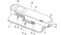
図1は本発明に係る燃料電池ユニットの一実施形態を示す外観図である。図1に示すように、この燃料電池ユニット10は、情報処理装置、例えばノート型パーソナルコンピュータの後部を載置するための載置部11と、燃料電池ユニット本体12とから構成される。燃料電池ユニット本体12には、電気化学反応で発電を行うDMFCスタックや、DMFCスタックに対して燃料となるメタノールや空気を注入、循環させるための補機(ポンプやバルブ等)を内蔵している。
FIG. 1 is an external view showing an embodiment of a fuel cell unit according to the present invention. As shown in FIG. 1, the
また、燃料電池ユニット本体12のユニットケース12a内部の例えば左端に、着脱可能な燃料カートリッジ(図示していない)が内蔵されており、この燃料カートリッジを交換できるように、カバー12bは取り外し可能となっている。
In addition, a removable fuel cartridge (not shown) is built in, for example, the left end of the
載置部11には情報処理装置が載置される。載置部11の上面には、情報処理装置と接続するための接続部としてドッキングコネクタ14が設けられている。一方、情報処理装置の例えば底面後部には、燃料電池ユニット10と接続するための接続部としてドッキングコネクタ21(図示していない)が設けられており、燃料電池ユニット10のドッキングコネクタ14と機械的、電気的に接続される。また、載置部11上に三箇所の位置決め突起15とフック16が設けられており、対応して設けられた情報処理装置の底面後部の三箇所の穴に、位置決め突起15とフック16が挿入される。
An information processing apparatus is placed on the
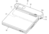
情報処理装置を燃料電池ユニット10から取り外す時は、図2に示した燃料電池ユニット10のイジェクトボタン17を押すことにより、ロック機構(図示していない)の解除が行われて、容易に取り外すことができる。
When removing the information processing apparatus from the
また、燃料電池ユニット本体12の例えば右側面には、発電設定スイッチ112と燃料電池運転スイッチ116が設けられる。
In addition, a power
発電設定スイッチ112は、燃料電池ユニット10での発電を許可或いは禁止するためにユーザが予め設定するためのスイッチであり、例えばスライド型スイッチで構成される。
The power
燃料電池運転スイッチ116は、例えば、燃料電池ユニット10で発電される電力で情報処理装置18が動作している時に、情報処理装置18の動作は継続しつつ燃料電池ユニット10での発電のみを停止させるような場合等に用いる。この場合、情報処理装置18は内蔵された二次電池の電力を用いて動作を継続することになる。燃料電池運転スイッチ116は、例えばプッシュスイッチ等で構成される。
For example, when the
図2は、情報処理装置18(例えば、ノート型パーソナルコンピュータ)を燃料電池ユニット10の載置部11の上に載置、接続した時の外観を示す図である。
FIG. 2 is a diagram showing an external appearance when the information processing apparatus 18 (for example, a notebook personal computer) is placed on and connected to the
なお、図1、図2に示した燃料電池ユニット10の形状や大きさ、或いはドッキングコネクタ14の形状や位置等は、種々の形態が考えられる。
Various shapes are conceivable for the shape and size of the
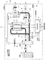
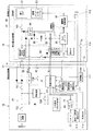
図3は、本発明に係る燃料電池ユニット10の一実施形態の系統図を示したものであり、特にDMFCスタックとその周辺に設けられた補機について細部の系統を示している。
FIG. 3 is a system diagram of an embodiment of the
燃料電池ユニット10は、発電部40と、燃料電池ユニット10の制御部である燃料電池制御部41とから構成される。燃料電池制御部41は発電部40の制御を行う他、情報処理装置18との通信を行う通信制御部としての機能を有する。
The
発電部40は、発電を行うための中心となるDMFCスタック42を有する他、燃料となるメタノールを収納する燃料カートリッジ43を有する。燃料カートリッジ43には高濃度のメタノールが封入されている。燃料カートリッジ43は、燃料を消費した時には容易に交換できるよう、着脱可能となっている。
The
また、一般に、ダイレクトメタノール型燃料電池においては、発電効率をあげるためにクロスオーバ現象を低減する必要がある。このために高濃度メタノールを希釈して低濃度化し、これを燃料極47に注入することが有効である。この実現のため、燃料電池ユニット10では、希釈循環システム62を採用しており、発電部40に希釈循環システム62の実現に必要な補機63を設ける。
In general, in a direct methanol fuel cell, it is necessary to reduce the crossover phenomenon in order to increase power generation efficiency. For this purpose, it is effective to dilute high-concentration methanol to lower the concentration and inject it into the
補機63には液体流路に設けられるものと気体流路に設けられるものがある。
There are
液体流路に設けられる補機63の接続関係は、燃料電池カートリッジ43の出力部から燃料供給ポンプ44が配管接続され、さらに燃料供給ポンプ44の出力部から混合タンク45に接続される。さらに、混合タンク45の出力部は送液ポンプ46に接続され、送液ポンプ46の出力部はDMFCスタック42の燃料極47に接続される。燃料極47の出力部は混合タンク45に配管接続される。また、水回収タンク55の出力部は水回収ポンプ56に配管接続され、水回収ポンプは混合タンク45へ接続される。
The
一方、気体流路においては、送気ポンプ50が送気バルブ51を介してDMFCスタック42の空気極52に接続される。空気極52の出力部は凝縮器53に接続される。また、混合タンク45からも、混合タンクバルブ48を介して凝縮器53に接続される。凝縮器53は排気バルブ57を介して排気口58に接続される。また、冷却ファン54は凝縮器53の近傍に配設される。
On the other hand, in the gas flow path, the
次に、燃料電池ユニット10の発電部40の発電メカニズムについて、燃料と空気(酸素)の流れに沿って説明する。
Next, the power generation mechanism of the
まず、燃料カートリッジ43内の高濃度メタノールは、燃料供給ポンプ44によって、混合タンク45に流入する。混合タンク45の内部で高濃度メタノールは、回収された水や燃料極47からの低濃度メタノール(発電反応の残余分)等と混合されて希釈され、低濃度メタノールが生成される。低濃度メタノールの濃度は発電効率の高い濃度(例えば3〜6%)を保てるように制御される。この制御は、例えば、濃度センサ60の情報を基に燃料供給ポンプ44によって混合タンク45に供給される高濃度メタノールの量を制御する。または、混合タンク45に環流する水の量を水回収ポンプ56等で制御することによって実現できる。
First, the high-concentration methanol in the
混合タンク45で希釈されたメタノール水溶液は送液ポンプ46で加圧されて、DMFCスタック42の燃料極(負極)47に注入される。燃料極47では、メタノールの酸化反応が行われることで電子が発生する。酸化反応で生成される水素イオン(H+)はDMFCスタック42内の固体高分子電解質膜422を透過して空気極(正極)52に達する。
The methanol aqueous solution diluted in the
一方、燃料極47で行われる酸化反応によって生成される二酸化炭素は、反応に供されなかったメタノール水溶液とともに再び混合タンク45に環流する。二酸化炭素は混合タンク45内で気化し、混合タンクバルブ48を介して、凝縮器53へ向かい、最終的には排気バルブ57を介して、排気口58から外部へ排気される。
On the other hand, the carbon dioxide produced by the oxidation reaction performed at the
他方、空気(酸素)の流れは、吸気口49から取り込まれ、送気ポンプ50で加圧され、送気バルブ51を介し空気極(正極)52に注入される。空気極52では、酸素(O2)の還元反応が進行し、外部の負荷からの電子(e―)と、燃料極47からの水素イオン(H+)と、酸素(O2)から水(H2O)が水蒸気として生成される。この水蒸気は空気極52から排出され、凝縮器53に入る。凝縮器53では、冷却ファン54によって水蒸気が冷却されて水(液体)となり、水回収タンク55内に一時的に蓄積される。この回収された水は水回収ポンプ56によって混合タンク45へと環流し、高濃度メタノールを希釈するための希釈循環システム62が構成される。
On the other hand, the flow of air (oxygen) is taken from the
この希釈循環システム62による燃料電池ユニット10の発電メカニズムからわかるように、DMFCスタック42から電力が取り出す、即ち、発電を開始するために、各部のポンプ44,46,50,56やバルブ48、51、57或いは冷却ファン54等の補機63を駆動させる。これによってメタノール水溶液と空気(酸素)がDMFCスタック42内に注入されそこで電気化学反応が進行することによって電力が得られる。一方、発電を停止するには、これらの補機63の駆動を停止することによる。
As can be seen from the power generation mechanism of the
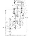
図4は、本発明に係る燃料電池ユニット10が接続される情報処理装置18のシステム構成を示したものである。
FIG. 4 shows a system configuration of the
情報処理装置18は、CPU65、主記憶66、ディスプレイコントローラ67、ディスプレイ68、HDD(Hard Disc Drive)69、キーボードコントローラ70、ポインタデバイス71、キーボード72、FDD(Floppy Disc Drive)73、これら構成品間において信号を伝送するバス74、バス74を介して伝送される信号を変換するためのノースブリッジ75、サウスブリッジ76と呼ばれるデバイス等から構成される。また、情報処理装置18の内部に電源部79を設け、ここに二次電池80として、例えばリチウムイオン電池を保有している。電源部79は、制御部77(以降、電源制御部77と記載する)によって制御される。
The
燃料電池ユニット10と情報処理装置18との電気的インタフェースとして制御系インタフェースと電源系インタフェースとを設ける。制御系インタフェースは情報処理装置18の電源制御部77と燃料電池ユニット10の制御部41との間にて通信を行うために設けられるインタフェースである。制御系インタフェースを介して情報処理装置18と燃料電池ユニット10との間で行われる通信は、例えばI2Cバス78といったシリアルバスを介して行われる。
As an electrical interface between the
電源系インタフェースは、燃料電池ユニット10と情報処理装置18との間における電力の授受のために設けられるインタフェースである。例えば、発電部40のDMFCスタック42で発電された電力が制御部41(以降、燃料電池制御部41と記載する)およびドッキングコネクタ14、21を介して情報処理装置18に供給される。また、電源系インタフェースには、情報処理装置18の電源部79から、燃料電池ユニット10内の補機63等への電力供給83もある。
The power supply system interface is an interface provided for power transfer between the
なお、情報処理装置18の電源部79に対してACアダプタ用コネクタ81を介してAC/DC変換された直流電源が供給され、これによって情報処理装置18の動作、二次電池(リチウムイオン電池)80の充電が可能である。
Note that a DC power source that is AC / DC converted is supplied to the
図5は、燃料電池ユニット10の燃料電池制御部41と、情報処理装置18の電源部79との、接続関係を示す構成例である。
FIG. 5 is a configuration example showing a connection relationship between the fuel
燃料電池ユニット10と情報処理装置18とはドッキングコネクタ14、21によって機械的かつ電気的に接続される。ドッキングコネクタ14、21には、燃料電池ユニット10のDMFCスタック42で発電された電力を情報処理装置18へ供給するための第一の電源端子(出力電源端子)91および、情報処理装置18から、燃料電池ユニット10のマイクロコンピュータ95にレギュレータ94を介して電源を供給し、かつ補機用電源回路97にスイッチ101を介して電源を供給するための第二の電源端子(補機用入力電源端子)92を有する。また、情報処理装置18からEEPROM99へ電源供給するための第三の電源端子92aを有している。
The
さらに、ドッキングコネクタ14、21は情報処理装置18の電源制御部77と燃料電池ユニット10のマイクロコンピュータ95との通信や、書き込み可能な不揮発性メモリ(EEPROM)99との通信、を行うための通信用入出力端子93を有している。
Further, the
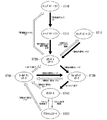
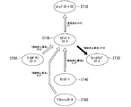
次に、図5に示した接続図と、図6に示した燃料電池ユニット10の状態遷移図とを用いて、燃料電池ユニット10から情報処理装置18へ、燃料電池ユニット10に設けられるDMFCスタック42の電力が供給されるまでの基本的な処理の流れを説明する。
Next, using the connection diagram shown in FIG. 5 and the state transition diagram of the
なお、情報処理装置18の二次電池(リチウムイオン電池)80には所定の電力が充電されているものとする。また、図5の中のスイッチは全て開いているものとする。
It is assumed that the secondary battery (lithium ion battery) 80 of the
まず、情報処理装置18は、コネクタ接続検出部111から出力される信号に基いて、情報処理装置18と燃料電池ユニット10とが機械的および電気的に接続されたことを認識する。この認識は、コネクタ接続検出部111が例えばコネクタ接続検出部111へ入力される信号に基いて、ドッキングコネクタ14、21の接続によって燃料電池ユニット10の内部で接地されることを検出することによって行われる。
First, the
また、情報処理装置18の電源制御部77は、燃料電池ユニット10の発電設定スイッチ112の設定が発電許可設定であるか発電禁止設定であるかを認識する。例えば、発電設定スイッチ検出部113へ入力される信号に基いて、発電設定スイッチ検出部113が発電設定スイッチ112の設定状態に応じて接地状態であるか或いは解放状態であるか否かを検出する。発電設定スイッチ112が解放状態である場合は、電源制御部77は発電禁止設定として認識する。
Further, the
発電設定スイッチ112が発電禁止設定である状態は、図6の状態遷移図において「ストップステート(0)」ST10に相当する状態である。
The state in which the power
情報処理装置18と燃料電池ユニット10とがドッキングコネクタ14、21を介して機械的に接続されると、情報処理装置18側から第三の電源端子92aを介して燃料電池制御部41の記憶部である不揮発性メモリ(EEPROM)99に電源が供給される。このEEPROM99には、燃料電池ユニット10の識別情報等が予め記憶される。識別情報には、例えば燃料電池ユニットの部品コードや製造シリアル番号、或いは定格出力などの情報を予め含ませることができる。また、このEEPROM99は、例えば、I2Cバス93といったシリアルバスに接続されており、EEPROM99に記憶されているデータはこのEEPROM99に電源が供給されている状態において読み出し可能である。図5の構成では、電源制御部77が通信用入出力端子93を介してEEPROM99の情報を読み出すことが可能である。
When the
この状態においては、燃料電池ユニット10は発電を行っておらず、また燃料電池ユニット10の内部の状態は、EEPROM99の電源以外は電源が供給されていない状態である。
In this state, the
ここで、ユーザが発電設定スイッチ112の設定を発電許可設定に設定すると(図5では発電設定スイッチを接地状態側に設定する)、情報処理装置18に設けられる電源制御部77は、燃料電池ユニット10に設けられるEEPROM99に記憶された識別情報を読み出すことが可能となる。この状態が、図6の「ストップステート(1)」ST11の状態である。
Here, when the user sets the power
換言すると、ユーザが発電設定スイッチ112を発電許可設定に設定しない限り、即ち発電禁止設定の設定である限り、「ストップステート(0)」ST10の状態であり、燃料電池ユニット10における発電を禁止することが可能である。
In other words, unless the user sets the power
なお、発電設定スイッチは、例えばスライドスイッチ等のように開または閉の状態をいずれか一方の状態に保持できるものが好ましい。 The power generation setting switch is preferably a switch that can maintain the open or closed state in one of the states, such as a slide switch.
電源制御部77による識別情報の読み出しは、I2Cバス78といったシリアルバスを介して燃料電池ユニット10に設けられるEEPROM99に記憶されている燃料電池ユニット10の識別情報を読み出すことによって行われる。
Reading of the identification information by the power
電源制御部77が読み出された識別情報に基いて、情報処理装置18に接続されている燃料電池ユニット10が情報処理装置18に適合した燃料電池ユニットであると判断した場合、図6の状態は、「ストップステート(1)」ST11から「スタンバイステート」ST20に遷移する。
When the power
具体的には、情報処理装置18に設けられる電源制御部77は、情報処理装置18に設けられるスイッチ100を閉じることによって、二次電池80の電力を第1の電源端子92を介して燃料電池ユニット10へ供給し、レギュレータ94を介してマイクロコンピュータ95へ電源が供給される。
Specifically, the power
この「スタンバイステート」ST20の状態では、燃料電池ユニット10に設けられるスイッチ101は開いており、補機用電源回路97には電源は供給されていない。従って、この状態において補機63は動作していない。
In the “standby state” ST20, the
しかしながら、マイクロコンピュータ95は動作を開始しており、情報処理装置18に設けられる電源制御部77から、I2Cバス78を介して各種の制御用コマンドを受信することが可能な状態である。また、マイクロコンピュータ95は、燃料電池ユニット10の電源情報を、I2Cバスを介して情報処理装置18へ送信可能な状態である。
However, the
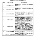
図7は、情報処理装置18に設けられる電源制御部77から、燃料電池制御部41に設けられるマイクロコンピュータ95に送られる制御用コマンドの一例を示した図である。
FIG. 7 is a diagram illustrating an example of a control command sent from the power
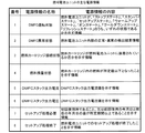
図8は、燃料電池制御部41に設けられるマイクロコンピュータ95から情報処理装置18に設けられる電源制御部77に送られる電源情報の一例を示した図である。
FIG. 8 is a diagram showing an example of power supply information sent from the
情報処理装置18に設けられる電源制御部77は、図8の電源情報のうち「DMFC運転状態」(図8の番号1)を読み取ることによって、燃料電池ユニット10が「スタンバイステート」ST20であること認識する。
The power
この「スタンバイステート」ST20の状態で、電源制御部77が、図7に示した制御用コマンドのうち「DMFC運転ON要求」コマンド(発電開始コマンド)を燃料電池制御部41に送ると、これを受信した燃料電池制御部41は、燃料電池ユニット10の状態を「ウォームアップステート」ST30に移行させる。
When the power
具体的には、マイクロコンピュータ95からの制御によって燃料電池制御部41に設けられるスイッチ101を閉じて補機用電源回路97に情報処理装置18からの電源を供給する。併せて、マイクロコンピュータ95から送信される補機用制御信号によって、発電部40に設けられる補機63、即ち、図4に示した各ポンプ44、46、50、56、バルブ48、51、57及び冷却ファン54等を駆動させる。さらにマイクロコンピュータ95は、燃料電池制御部41に設けられたスイッチ102を閉じる。
Specifically, the
この結果、発電部40に設けられるDMFCスタック42に対してメタノール水溶液や空気が注入され、発電が開始される。また、DMFCスタック42による発電電力は、情報処理装置18に供給が開始される。ただし、発電出力は、瞬時に定格値に達するわけではないため、定格値に達するまでの状態を「ウォームアップステート」ST30と呼んでいる。
As a result, a methanol aqueous solution or air is injected into the
燃料電池制御部41に設けられるマイクロコンピュータ95は、例えばDMFCスタック42の出力電圧およびDMFCスタック42の温度をモニタすることにより、DMFCスタック42の出力が定格値に達したと判断すると、燃料電池ユニット10に設けられるスイッチ101を開き、補機63への電力供給源を情報処理装置18からDMFCスタック42に切り替える。この状態が「オンステート」ST40である。
When the
以上が「ストップステート」ST10から「オンステート」ST40への処理の流れの概要である。 The above is the outline of the processing flow from the “stop state” ST10 to the “on state” ST40.
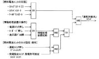
図9は、情報処理装置18に設けられる電源制御部77が「DMFC運転ON要求」コマンドを燃料電池ユニット10に設けられるマイクロコンピュータ95に送信するための条件を示した論理図である。
FIG. 9 is a logic diagram showing conditions for the power
まず、「DMFC運転ON要求」コマンドが送信されるための第1の条件は、燃料電池ユニット10の状態が、ストップステート(2)ST12、スタンバイステートST20或いはクールダウンステートST50のうちのいずれかの状態である。これら3つの状態は、図6の状態遷移図からわかるように、いずれも発電設定スイッチの設定が発電許可設定の設定になっている場合に限り可能な状態である。
First, the first condition for transmitting the “DMFC operation ON request” command is that the state of the
「DMFC運転ON要求」コマンドが送信されるための第2の条件は、情報処理装置18が有する何らかの情報処理装置起動手段によって情報処理装置18が起動されることである。情報処理装置起動手段の一例としては、情報処理装置18に設けられた電源スイッチ114のオン操作が考えられる。電源スイッチ114が押されたことを電源制御部77が検出することによって情報処理装置18は起動される。
The second condition for transmitting the “DMFC operation ON request” command is that the
この他、情報処理装置18が例えばノート型パーソナルコンピュータである場合、動作中に表示パネルを閉じると情報処理装置18は一旦動作を停止するが、再度表示パネルを開くと情報処理装置18は再起動する。この場合、表示パネルが開かれたことを機械的に検出するスイッチ115が情報処理装置起動手段となる。
In addition, when the
また、情報処理装置18が動作中に所定の時間、操作されなかった場合、主として節電を目的としてレジュームモードとなるが、例えばキーボード72のいずれかのキーが押されたことをキーボードコントローラ70が検出し、この情報をもとに電源制御部77が情報処理装置18を再度起動させることができる。この場合キーボードコントローラ70の検出手段が情報処理装置起動手段となる。
Further, if the
「DMFC運転ON要求」コマンドが送信されるための第2の条件は、上述したようにいずれも情報処理装置18に対する起動操作である。
The second condition for transmitting the “DMFC operation ON request” command is an activation operation on the
したがって、ユーザは情報処理装置18の電源が燃料電池ユニット10であることを意識することなく、情報処理装置18の起動方法によって燃料電池ユニット10を定常な発電状態、即ち「オンステート」ST40へ遷移させることが可能となる。
Therefore, the user transitions the
なお、「DMFC運転ON要求」コマンドが送信されるための第1の条件は、燃料電池ユニット10をドッキングコネクタ14,21を介して情報処理装置18に取り付け、発電設定スイッチ112を発電許可設定に設定し、燃料電池ユニット10を自動的に「スタンバイステート」ST20に遷移させることである。
The first condition for transmitting the “DMFC operation ON request” command is that the
以上に示したように、本発明によれば、燃料電池ユニット10を電源とする情報処理装置であっても、情報処理装置18の起動手順に連動させて燃料電池ユニット10の発電開始のシーケンスを進めることによって操作の簡便化を図り、ユーザに対する利便性を向上させることができる。
As described above, according to the present invention, even if the information processing device uses the
なお、図6の状態遷移図には「ストップステート(2)」ST12が示されている。「ストップステート(2)」ST12は、「スタンバイステート」ST20の状態が、例えば1分以上といった所定の時間以上、継続したような場合に強制的に「ストップステート(2)」ST12へ遷移させるものである。これは、「スタンバイステート」ST20の状態で「DMFC運転ON要求」コマンドが所定の時間以上、情報処理装置18から送信されないような場合に、電源制御部77は情報処理装置18に設けられる二次電池80から燃料電池ユニット10への供給電力を停止させ(情報処理装置18に設けられるスイッチ100を開く)、「DMFC運転ON要求」コマンドを送信する要因が発生した場合に(例えば情報処理装置18の電源スイッチ114が押された場合)、電源制御部77は再度スイッチ100を閉じた後、「DMFC運転ON要求」コマンドを燃料電池ユニット10に設けられるマイクロコンピュータ95へ送信する制御である。
In the state transition diagram of FIG. 6, “stop state (2)” ST12 is shown. The “stop state (2)” ST12 is forcibly shifted to the “stop state (2)” ST12 when the state of the “standby state” ST20 continues for a predetermined time, for example, 1 minute or longer. It is. This is because when the “DMFC operation ON request” command is not transmitted from the
次に、燃料電池ユニット10の発電停止の基本的なシーケンスについて説明する。
Next, a basic sequence for stopping power generation of the
情報処理装置18に設けられる電源制御部77は、燃料電池ユニット10に設けられるマイクロコンピュータ95の電源情報をI2Cバス78を介して読み出すことによって、DMFC運転状態(図8の番号1)が「ウォームアップステート」ST30或いは「オンステート」ST40のいずれかであることを認識する。
The power
発電停止のシーケンスが開始される状態のうちの一つの状態である「オンステート」ST40を例にとって説明する。 An explanation will be given by taking "ON state" ST40, which is one of the states where the power generation stop sequence is started, as an example.
燃料電池ユニット10が「オンステート」ST40にある時に、電源制御部77から燃料電池ユニット10に設けられるマイクロコンピュータ95に対して「DMFC運転OFF要求」コマンド(発電停止コマンド)が送信されると、燃料電池ユニット10の状態は「オンステート」ST40から「クールダウンステート」ST50に遷移する(図6参照)。
When the “DMFC operation OFF request” command (power generation stop command) is transmitted from the power
「クールダウンステート」ST50の内容は次の通りである。 The contents of the “cool down state” ST50 are as follows.
まず、マイクロコンピュータ95が燃料電池ユニット内に設けられるスイッチ101を閉じることで、補機63を駆動させるために使用される補機用電源回路97の電力源を、第1の電源端子92を介して供給される二次電池80に切替える。
First, the
さらに,マイクロコンピュータ95が燃料電池ユニット内に設けられるスイッチ102を開くことで、DMFCスタック42にて発電される電力の情報処理装置18への供給を停止する。
Further, the
次に、マイクロコンピュータ95が送気ポンプ50を停止させるとともに、送液ポンプ46を作動させ、このポンプ作動状態を所定期間継続する。この作動によって燃料極47の内部の送液経路内に付着した二酸化炭素の気泡を流失・除去することができる。
Next, the
次に、マイクロコンピュータ95が送液ポンプ46を停止し、送気ポンプ50を最大能力で作動させる。このポンプ作動状態を所定期間継続する。この作動によって空気極52の内部の送気経路内に付着した水滴を流失・除去することができる。
Next, the
DMFCスタックの発電によって発生した気泡や水滴を、発電の停止シーケンス中において自動的に流出・除去させることによって、次回発電を開始する時の発電効率を向上させることが可能となる。 By automatically flowing out and removing bubbles and water droplets generated by the power generation of the DMFC stack during the power generation stop sequence, it becomes possible to improve the power generation efficiency when starting the next power generation.
その後、燃料電池ユニット10の周囲外気から不要物が混入すること、および燃料電池ユニット10内にセットされる液体燃料が漏れることを避けるために、排気バルブ57や送気バルブ51を閉じる。さらに、マイクロコンピュータ95は補機用電源回路97から補機63への電力の供給を停止する。
Thereafter, the
以上が燃料電池ユニット10で行われる「クールダウンステート」ST50の処理内容である。
The above is the processing content of the “cool down state” ST50 performed in the
「クールダウンステート」ST50の処理は、例えば概ね30秒間行われ、クールダウン処理終了後は、DMFC運転状態(図8の番号1参照)を自動的に「スタンバイステート」に設定する。
The process of “cool down state” ST50 is performed, for example, for approximately 30 seconds. After the cool down process is completed, the DMFC operation state (see
情報処理装置18に設けられる電源制御部77は、I2Cバス78を介して燃料電池ユニット10の電源情報(図8に示した情報)を所定期間毎、例えば100ms毎に読み出しており、燃料電池ユニット10の電源情報が「スタンバイステート」になったこと認識する。
The power
この他、燃料電池ユニット10は、図6に示したように「リフレッシュステート」ST60を備える。「リフレッシュステート」ST60は、燃料電池ユニット10の発電効率を維持することを目的とするものである。所定期間毎に「オンステート」ST40から自動的に「リフレッシュステート」ST60に遷移し、所定期間のリフレッシュ処理が終了した後自動的に「オンステート」ST40の戻るものである。
In addition, the
リフレッシュ処理の内容は、「クールダウンステート」ST50の処理の内容と同様のものであり、DMFCスタック42の送気経路、送液経路に発生した不要な水滴や気泡を流失・除去させるものである。
The contents of the refresh process are the same as the contents of the “cool down state” ST50, and the unnecessary water droplets and bubbles generated in the air supply path and liquid supply path of the
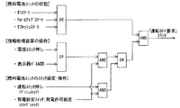
図10は、電源制御部77が「DMFC運転OFF要求」コマンドをマイクロコンピュータ95に送信するための条件を示した論理図である。
FIG. 10 is a logic diagram showing conditions for the power
電源制御部77が「DMFC運転OFF要求」コマンドを送信するための第1の条件は、燃料電池ユニット10の状態が「ウォームアップステート」ST30、「オンステート」ST40、または「リフレッシュステート」ST60のいずれかの状態にある時である。これら3つの状態は、図6の状態遷移図からわかるように、いずれも発電設定スイッチの設定が発電許可設定の設定になっている場合である。
The first condition for the power
電源制御部77が「DMFC運転OFF要求」コマンドを送信するための第2の条件は、情報処理装置18が有する何らかの情報処理装置停止手段によって情報処理装置18が停止されることである。情報処理装置停止手段の一例としては、情報処理装置18に設けられる電源スイッチ114がある。電源スイッチ114が押されたことを電源制御部77が検出することによって情報処理装置18は停止される。
The second condition for the power
この他、情報処理装置18が例えばノート型パーソナルコンピュータであるような場合において、その動作中に表示パネルを閉じることによって、情報処理装置18を停止させることができる。この場合、表示パネルが閉じられたことを検出するスイッチ115が情報処理装置停止手段となる。
In addition, when the
電源制御部77が「DMFC運転OFF要求」コマンドを送信するための第2の条件は、上述したようにいずれも情報処理装置18に対する停止操作である。
The second condition for the power
したがって、ユーザは情報処理装置18の電源が燃料電池ユニット10であることを意識することなく、情報処理装置18の停止方法によって燃料電池ユニット10を「オンステート」ST40からへ「クールダウンステート」ST50を経て「スタンバイステート」ST20に遷移させることが可能となる。
Therefore, the user can change the
なお、図6に示したように、燃料電池ユニット10の状態が「ウォームアップステート」ST30または「リフレッシュステート」ST60の状態の時に、電源制御部77が「DMFC運転OFF要求」コマンドを送信した場合においても、「クールダウンステート」ST50を経て「スタンバイステート」ST20に遷移する。
As shown in FIG. 6, when the
上述したように、燃料電池ユニットを電源とする情報処理装置であっても、情報処理装置18の停止に連動させて燃料電池ユニット10の発電停止のシーケンスを進めることによって操作の簡便化を図り、ユーザに対する利便性を向上させることができる。
As described above, even in the information processing apparatus using the fuel cell unit as a power source, the operation is simplified by advancing the power generation stop sequence of the
なお、電源制御部77は、二次電池80の残量が所定値未満である場合は二次電池80を所定値以上に充電した後に「DMFC運転OFF要求」コマンドを送信してもよい。
Note that, when the remaining amount of the
この他、燃料電池ユニット10は、運転スイッチ116を設けている。この運転スイッチ116は例えばプッシュスイッチ等で構成される。
In addition, the
運転スイッチ116は、例えば発電設定スイッチ112が発電許可設定に設定されているために燃料電池ユニット10の状態が「スタンバイステート」ST20、または「ストップステート(2)」ST12である場合において、燃料電池ユニット10の発電シーケンスを開始するような場合に用いるものである。この場合、情報処理装置18の情報処理装置起動手段を用いなくとも燃料電池ユニット10に設けられる運転スイッチ116が押されたことを電源制御部77が検出し、電源制御部77が「DMFC運転ON要求」コマンドをマイクロコンピュータ95に送信することによって、発電開始のシーケンスが開始される。
The
図11は、燃料電池ユニット10を緊急停止させる場合の状態遷移図を示した図である。
FIG. 11 is a diagram showing a state transition diagram when the
燃料電池ユニット10が、「ウォームアップステート」ST30、「オンステート」ST40或いは「クールダウンステート」ST50のいずれかの状態にあるときに、電源制御部77が「強制停止要求コマンド」をマイクロコンピュータ95に送信すると、「クールダウンステート」ST50を経ることなく、また「クールダウンステート」ST50であればクールダウン処理を途中で停止して、送気バルブ51、排気バルブ57および混合タンクバルブ48を閉じた後、「スタンバイステート」ST20へ移行する。その後、情報処理装置18に設けられるスイッチ100を開いて二次電池80からの電力供給を停止させて「ストップステート(0)」へ遷移させる。
When the
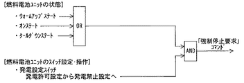
図12に示したように、「強制停止要求コマンド」は、燃料電池ユニット10が「ウォームアップステート」ST30、「オンステート」ST40或いは「クールダウンステート」ST50のいずれかの状態にあるときに(第1の条件)、燃料電池ユニット10に設けられる発電設定スイッチ112が発電許可設定から発電禁止設定に設定変更された場合に(第2の条件)、送信される。
As shown in FIG. 12, the “forced stop request command” is issued when the
このように、なんらかの要因で燃料電池ユニット10の発電を緊急に停止する必要性が発生した場合には、発電設定スイッチ112を発電禁止設定にすることによって短時間での発電の停止が可能である。
As described above, when it is necessary to urgently stop the power generation of the
なお、本発明は上記実施形態そのままに限定されるものではなく、実施段階ではその要旨を逸脱しない範囲で構成要素を変形して具体化できる。また、上記実施形態に開示されている複数の構成要素の適宜な組み合わせにより、種々の発明を形成できる。例えば、実施形態に示される全構成要素から幾つかの構成要素を削除してもよい。さらに、異なる実施形態にわたる構成要素を適宜組み合わせても良い。 Note that the present invention is not limited to the above-described embodiment as it is, and can be embodied by modifying the constituent elements without departing from the scope of the invention in the implementation stage. In addition, various inventions can be formed by appropriately combining a plurality of components disclosed in the embodiment. For example, some components may be deleted from all the components shown in the embodiment. Furthermore, the constituent elements over different embodiments may be appropriately combined.
10 燃料電池ユニット
14 ドッキングコネクタ(燃料電池ユニット側)
18 情報処理装置
21 ドッキングコネクタ(情報処理装置側)
22 発電設定スイッチ
23 運転スイッチ
40 発電部
41 燃料電池制御部
42 DMFCスタック
422 固体高分子電解質膜
46 送液ポンプ
50 送気ポンプ
51 送気バルブ
57 排気バルブ
63 補機
70 キーボードコントローラ
72 キーボード
77 電源制御部
79 電源部
80 二次電池
95 マイクロコンピュータ
97 補機用電源回路
99 不揮発性メモリ(EEPROM)
114 電源スイッチ
115 表示器パネル開閉検出スイッチ
10
18
22 Power generation setting switch 23
114
Claims (16)
前記接続部を介して前記外部機器に供給される電力を、燃料電池を用いて発電する発電部と、
前記燃料電池に少なくとも燃料を注入する補機と
前記発電部での発電を許可する発電許可設定に設定可能な発電設定スイッチと、
前記発電設定スイッチの設定が発電許可設定の場合、前記接続部を介して前記外部機器から送信される、前記発電部での発電を開始させる発電開始コマンドを受信した後、前記補機を駆動させて発電を開始させる制御部と、
を備えたことを特徴とする燃料電池ユニット。 A connection part used for connection with an external device;
A power generation unit that generates electric power supplied to the external device through the connection unit using a fuel cell;
An auxiliary machine that injects at least fuel into the fuel cell; a power generation setting switch that can be set to a power generation permission setting that permits power generation in the power generation unit;
When the setting of the power generation setting switch is a power generation permission setting, after receiving a power generation start command transmitted from the external device via the connection unit to start power generation in the power generation unit, the auxiliary machine is driven. A control unit for starting power generation,
A fuel cell unit comprising:
本燃料電池ユニットが、
前記発電部で発電した電力を前記接続部を介して前記外部機器に供給している状態、
前記発電部で発電した電力の前記外部機器への供給を停止した後、前記補機が駆動している状態、
前記補機の駆動が停止している状態、
のうちのいずれの状態であるかを示す情報を前記接続部を介して前記外部機器に送信することを特徴とする請求項1に記載の燃料電池ユニット。 The controller is
This fuel cell unit
A state in which power generated by the power generation unit is supplied to the external device via the connection unit,
After stopping the supply of the power generated by the power generation unit to the external device, the auxiliary machine is driving,
A state in which the driving of the auxiliary machine is stopped;
2. The fuel cell unit according to claim 1, wherein information indicating which of the two states is transmitted to the external device via the connection unit.
本情報処理装置を起動させるための起動手段と、
前記補機を駆動するための電力を供給する電力供給部と、
前記発電部が発電可能な状態において、前記起動手段によって本情報処理装置が起動された場合、前記発電部における発電を開始させる発電開始コマンドを前記燃料電池ユニットに送信する制御部と、
を具備することを特徴とする情報処理装置。 In an information processing apparatus including a fuel cell unit having a power generation unit that generates power using a fuel cell and an auxiliary machine,
An activation means for activating the information processing apparatus;
A power supply unit for supplying power for driving the auxiliary machine;
A control unit that transmits a power generation start command for starting power generation in the power generation unit to the fuel cell unit when the information processing apparatus is activated by the activation unit in a state where the power generation unit can generate power;
An information processing apparatus comprising:
前記起動手段は、前記入力部の所定の操作に基いて、本情報処理装置を起動させる手段であることを特徴とする請求項5記載の情報処理装置。 An input unit;
The information processing apparatus according to claim 5, wherein the activation unit is a unit that activates the information processing apparatus based on a predetermined operation of the input unit.
前記本体に回動可能に取り付けられる表示部とをさらに有し、
前記起動手段は、前記表示部の前記本体に対して閉じられた状態から開かれた状態への変化に基いて、本情報処理装置を起動させる手段であることを特徴とする請求項5記載の情報処理装置。 The body,
A display unit rotatably attached to the main body,
The said starting means is a means to start this information processing apparatus based on the change from the closed state with respect to the said main body of the said display part to the opened state. Information processing device.
前記起動手段は、前記電源スイッチが押下操作されることに基いて、本情報処理装置を起動させる手段であることを特徴とする請求項5記載の情報処理装置。 A power switch,
6. The information processing apparatus according to claim 5, wherein the activation unit is a unit that activates the information processing apparatus based on a pressing operation of the power switch.
前記制御部は、前記停止手段によって本情報処理装置を停止させる時に、前記発電部の発電を停止させる発電停止コマンドを前記燃料電池ユニットへ送信することで、前記補機を駆動させる電力を前記発電部にて発電された電力から前記電力供給部が供給する電力に切替させることを特徴とする請求項5記載の情報処理装置。 A stopping means for stopping the information processing apparatus;
The control unit transmits power generation stop command for stopping power generation of the power generation unit to the fuel cell unit when the information processing apparatus is stopped by the stop unit, thereby generating electric power for driving the auxiliary machine. The information processing apparatus according to claim 5, wherein the information is switched from the power generated by the power supply unit to the power supplied by the power supply unit.
前記本体に回動可動に取り付けられる表示部とをさらに有し、
前記停止手段は、前記表示部の前記本体に対して開かれた状態から閉じられた状態への変化に基いて、本情報処理装置を停止させる手段であることを特徴とする請求項11記載の情報処理装置。 The body,
A display unit attached to the main body so as to be rotatable,
The said stop means is a means to stop this information processing apparatus based on the change from the state opened with respect to the said main body of the said display part to the closed state. Information processing device.
前記情報処理装置を情報処理装置起動手段によって起動し、
前記発電部での発電を許可する発電設定スイッチが発電許可設定に設定されているときに、発電開始コマンドを前記燃料電池ユニットに送信し、
前記燃料電池ユニットが前記発電開始コマンドを受信すると、前記情報処理装置に設けられた電力供給部からの電力で前記補機を駆動し、
前記補機の駆動によって前記発電部で発電を開始する電源起動方法と、
前記情報処理装置が情報処理装置停止手段によって停止処理を開始し、
前記燃料電池ユニットに前記発電部の発電を停止するための発電停止コマンドを送信し、
前記燃料電池ユニットが前記発電停止コマンドを受信すると、前記発電部で発電される電力の供給を停止し、
所定期間、前記電力供給部から供給される電力で補機を駆動し、
所定期間経過後、前記補機の駆動を停止する電源停止方法と
を備えたことを特徴とする情報処理装置の電源制御方法。 In a power supply control method for an information processing apparatus including a fuel cell unit having a power generation unit that generates power using a fuel cell and an auxiliary machine,
Starting the information processing apparatus by an information processing apparatus starting means;
When the power generation setting switch that permits power generation in the power generation unit is set to the power generation permission setting, a power generation start command is transmitted to the fuel cell unit,
When the fuel cell unit receives the power generation start command, the auxiliary machine is driven with power from a power supply unit provided in the information processing device,
A power activation method for starting power generation in the power generation unit by driving the auxiliary machine;
The information processing apparatus starts a stop process by the information processing apparatus stop means,
Transmitting a power generation stop command for stopping power generation of the power generation unit to the fuel cell unit;
When the fuel cell unit receives the power generation stop command, the supply of power generated by the power generation unit is stopped,
For a predetermined period, the auxiliary machine is driven by the electric power supplied from the power supply unit,
A power supply control method for an information processing apparatus, comprising: a power supply stop method for stopping driving of the auxiliary machine after a predetermined period of time has elapsed.
Priority Applications (4)
| Application Number | Priority Date | Filing Date | Title |
|---|---|---|---|
| JP2004108045A JP2005294065A (en) | 2004-03-31 | 2004-03-31 | Fuel cell unit, information processing apparatus, and power supply control method thereof |
| PCT/JP2005/005201 WO2005099007A1 (en) | 2004-03-31 | 2005-03-23 | Fuel cell unit, information processing device, and power source controlling method for information processing device |
| CNA2005800161394A CN1957493A (en) | 2004-03-31 | 2005-03-23 | Fuel cell unit, information processing apparatus, and power supply control method for information processing apparatus |
| US11/541,611 US20070072023A1 (en) | 2004-03-31 | 2006-09-28 | Fuel cell unit, information processing apparatus, and power supply control method for information processing apparatus |
Applications Claiming Priority (1)
| Application Number | Priority Date | Filing Date | Title |
|---|---|---|---|
| JP2004108045A JP2005294065A (en) | 2004-03-31 | 2004-03-31 | Fuel cell unit, information processing apparatus, and power supply control method thereof |
Publications (2)
| Publication Number | Publication Date |
|---|---|
| JP2005294065A true JP2005294065A (en) | 2005-10-20 |
| JP2005294065A5 JP2005294065A5 (en) | 2007-05-10 |
Family
ID=35125387
Family Applications (1)
| Application Number | Title | Priority Date | Filing Date |
|---|---|---|---|
| JP2004108045A Withdrawn JP2005294065A (en) | 2004-03-31 | 2004-03-31 | Fuel cell unit, information processing apparatus, and power supply control method thereof |
Country Status (4)
| Country | Link |
|---|---|
| US (1) | US20070072023A1 (en) |
| JP (1) | JP2005294065A (en) |
| CN (1) | CN1957493A (en) |
| WO (1) | WO2005099007A1 (en) |
Cited By (5)
| Publication number | Priority date | Publication date | Assignee | Title |
|---|---|---|---|---|
| JP2007184221A (en) * | 2006-01-05 | 2007-07-19 | Samsung Sdi Co Ltd | Direct methanol fuel cell system and method of operating direct methanol fuel cell system |
| JP2008071743A (en) * | 2006-09-13 | 2008-03-27 | Samsung Sdi Co Ltd | Fuel cell, and operation method of fuel cell |
| JP2008146950A (en) * | 2006-12-08 | 2008-06-26 | Ricoh Co Ltd | Fuel cell system, electronic device, and image forming device |
| JP2011096554A (en) * | 2009-10-30 | 2011-05-12 | Yamaha Motor Co Ltd | Fuel cell system and transportation apparatus having the same |
| US8142945B2 (en) * | 2005-11-10 | 2012-03-27 | Samsung Sdi Co., Ltd. | Method for controlling peripheral system and fuel cell system using the same |
Families Citing this family (7)
| Publication number | Priority date | Publication date | Assignee | Title |
|---|---|---|---|---|
| US20080118798A1 (en) * | 2006-11-17 | 2008-05-22 | Gallagher Emerson R | Fuel cell system apparatus |
| JP4803532B2 (en) * | 2007-04-06 | 2011-10-26 | Necカシオモバイルコミュニケーションズ株式会社 | Electronic device and electronic device program |
| TWI445240B (en) * | 2007-08-30 | 2014-07-11 | Yamaha Motor Co Ltd | Fuel cell system and control method therefor |
| EP2045863A1 (en) * | 2007-10-05 | 2009-04-08 | Atomic Energy Council - Institute of Nuclear Energy Research | Method for supplying fuel to fuel cell |
| DE102009036199A1 (en) * | 2009-08-05 | 2011-02-17 | Daimler Ag | Method for operating a fuel cell system in a vehicle |
| US9276271B2 (en) | 2010-12-14 | 2016-03-01 | Intelligent Energy Limited | Fuel cell system having a toggle switch |
| JPWO2019107240A1 (en) * | 2017-11-28 | 2020-12-17 | 京セラ株式会社 | Fuel cell system and equipment management method |
Family Cites Families (9)
| Publication number | Priority date | Publication date | Assignee | Title |
|---|---|---|---|---|
| JP3445561B2 (en) * | 2000-07-17 | 2003-09-08 | 株式会社東芝 | Computer system |
| JP2002169629A (en) * | 2000-11-30 | 2002-06-14 | Toshiba Corp | Information processing equipment |
| JP2003223243A (en) * | 2002-01-29 | 2003-08-08 | Toshiba Corp | Information equipment |
| JP3748434B2 (en) * | 2002-06-12 | 2006-02-22 | 株式会社東芝 | Direct methanol fuel cell system and fuel cartridge |
| JP2004087170A (en) * | 2002-08-23 | 2004-03-18 | Fuji Photo Film Co Ltd | Portable apparatus |
| TW200405962A (en) * | 2002-10-02 | 2004-04-16 | Hitachi Ltd | Electronic device using fuel cells |
| JP3720024B2 (en) * | 2003-01-10 | 2005-11-24 | 株式会社東芝 | Electronic device system and operation control method |
| JP2003288136A (en) * | 2003-01-20 | 2003-10-10 | Toshiba Corp | Computer system |
| US20050074656A1 (en) * | 2003-10-03 | 2005-04-07 | Hitachi Maxell, Ltd. | Fuel cell, electronic appliance and business method |
-
2004
- 2004-03-31 JP JP2004108045A patent/JP2005294065A/en not_active Withdrawn
-
2005
- 2005-03-23 WO PCT/JP2005/005201 patent/WO2005099007A1/en active Application Filing
- 2005-03-23 CN CNA2005800161394A patent/CN1957493A/en active Pending
-
2006
- 2006-09-28 US US11/541,611 patent/US20070072023A1/en not_active Abandoned
Cited By (7)
| Publication number | Priority date | Publication date | Assignee | Title |
|---|---|---|---|---|
| US8142945B2 (en) * | 2005-11-10 | 2012-03-27 | Samsung Sdi Co., Ltd. | Method for controlling peripheral system and fuel cell system using the same |
| JP2007184221A (en) * | 2006-01-05 | 2007-07-19 | Samsung Sdi Co Ltd | Direct methanol fuel cell system and method of operating direct methanol fuel cell system |
| US7759012B2 (en) | 2006-01-05 | 2010-07-20 | Samsung Sdi Co., Ltd. | Direct methanol fuel cell system and operating method thereof |
| JP2008071743A (en) * | 2006-09-13 | 2008-03-27 | Samsung Sdi Co Ltd | Fuel cell, and operation method of fuel cell |
| US8039159B2 (en) | 2006-09-13 | 2011-10-18 | Samsung Sdi Co., Ltd. | Fuel cell having actuator controlling unit and method of operating the same |
| JP2008146950A (en) * | 2006-12-08 | 2008-06-26 | Ricoh Co Ltd | Fuel cell system, electronic device, and image forming device |
| JP2011096554A (en) * | 2009-10-30 | 2011-05-12 | Yamaha Motor Co Ltd | Fuel cell system and transportation apparatus having the same |
Also Published As
| Publication number | Publication date |
|---|---|
| CN1957493A (en) | 2007-05-02 |
| WO2005099007A1 (en) | 2005-10-20 |
| US20070072023A1 (en) | 2007-03-29 |
Similar Documents
| Publication | Publication Date | Title |
|---|---|---|
| WO2005099007A1 (en) | Fuel cell unit, information processing device, and power source controlling method for information processing device | |
| US7618727B2 (en) | Fuel cell unit, control method for fuel cell unit, and information processing apparatus | |
| US20060083966A1 (en) | Fuel cell unit and method for controlling liquid volume | |
| JP2008034254A (en) | Fuel cell system and its operation control method | |
| US20070048566A1 (en) | Fuel cell unit, control method for fuel cell unit, and information processing apparatus | |
| JP4837015B2 (en) | Information processing apparatus system and charging control method | |
| US20070015018A1 (en) | Information processing apparatus and operation control method | |
| US7620805B2 (en) | Apparatus for updating program in a fuel cell unit | |
| US7879473B2 (en) | Fuel cell unit, control method thereof, information processing apparatus, and power supply control method thereof | |
| US20040183501A1 (en) | Electronic apparatus, electronic system, and method of controlling operation of the same | |
| JP2007273388A (en) | Fuel cell system and operation control method therefor | |
| JP2008117540A (en) | Fuel cell unit | |
| JP2005078353A (en) | Electronic device system and method for supplying electric power | |
| US20060068241A1 (en) | Information processing apparatus system, fuel cell unit, and display method thereof | |
| JP2005108711A (en) | Battery unit and electric power supply control method | |
| JP4746277B2 (en) | FUEL CELL UNIT, INFORMATION PROCESSING DEVICE, AND METHOD FOR POWER SUPPLYING INFORMATION PROCESSING DEVICE | |
| JP2006106887A (en) | Information processor system, fuel-cell unit and method for controlling charging | |
| JP4805551B2 (en) | Information processing apparatus system and power supply method | |
| JP2005242909A (en) | Information processing equipment and power supply control method of information processing equipment | |
| JP2006338968A (en) | Fuel cell unit and fuel cell control method | |
| JP2006310040A (en) | Fuel cell unit |
Legal Events
| Date | Code | Title | Description |
|---|---|---|---|
| A521 | Request for written amendment filed |
Free format text: JAPANESE INTERMEDIATE CODE: A523 Effective date: 20070316 |
|
| A621 | Written request for application examination |
Free format text: JAPANESE INTERMEDIATE CODE: A621 Effective date: 20070316 |
|
| A761 | Written withdrawal of application |
Free format text: JAPANESE INTERMEDIATE CODE: A761 Effective date: 20100204 |