JP2005293860A - Electronic equipment - Google Patents
Electronic equipment Download PDFInfo
- Publication number
- JP2005293860A JP2005293860A JP2004102644A JP2004102644A JP2005293860A JP 2005293860 A JP2005293860 A JP 2005293860A JP 2004102644 A JP2004102644 A JP 2004102644A JP 2004102644 A JP2004102644 A JP 2004102644A JP 2005293860 A JP2005293860 A JP 2005293860A
- Authority
- JP
- Japan
- Prior art keywords
- battery
- case
- battery device
- contact
- wall
- Prior art date
- Legal status (The legal status is an assumption and is not a legal conclusion. Google has not performed a legal analysis and makes no representation as to the accuracy of the status listed.)
- Granted
Links
- 230000037431 insertion Effects 0.000 claims description 21
- 238000003780 insertion Methods 0.000 claims description 21
- 238000010586 diagram Methods 0.000 description 5
- 230000004308 accommodation Effects 0.000 description 4
- 230000037303 wrinkles Effects 0.000 description 4
- 238000000605 extraction Methods 0.000 description 2
- 230000007246 mechanism Effects 0.000 description 2
- 230000000694 effects Effects 0.000 description 1
- 238000004519 manufacturing process Methods 0.000 description 1
- 230000013011 mating Effects 0.000 description 1
- 230000006641 stabilisation Effects 0.000 description 1
- 238000011105 stabilization Methods 0.000 description 1
- 230000000087 stabilizing effect Effects 0.000 description 1
Images

Classifications
-
- Y—GENERAL TAGGING OF NEW TECHNOLOGICAL DEVELOPMENTS; GENERAL TAGGING OF CROSS-SECTIONAL TECHNOLOGIES SPANNING OVER SEVERAL SECTIONS OF THE IPC; TECHNICAL SUBJECTS COVERED BY FORMER USPC CROSS-REFERENCE ART COLLECTIONS [XRACs] AND DIGESTS
- Y02—TECHNOLOGIES OR APPLICATIONS FOR MITIGATION OR ADAPTATION AGAINST CLIMATE CHANGE
- Y02E—REDUCTION OF GREENHOUSE GAS [GHG] EMISSIONS, RELATED TO ENERGY GENERATION, TRANSMISSION OR DISTRIBUTION
- Y02E60/00—Enabling technologies; Technologies with a potential or indirect contribution to GHG emissions mitigation
- Y02E60/10—Energy storage using batteries
Landscapes
- Battery Mounting, Suspending (AREA)
Abstract
Description
本発明はバッテリー装置により動作する電子機器に関する。 The present invention relates to an electronic device operated by a battery device.
従来から、左右方向の幅と上下方向の厚さと前後方向の長さを有し、かつ、上下方向で対向する上面、下面と、前記長さ方向で対向する前面、後面とを有する矩形板状に形成されたケースと、ケースの内部に設けられた充電池部と、ケースの前面に設けられ充電池部に接続されたバッテリー側端子とを備えたバッテリー装置が提供されている(例えば特許文献1参照)。
また、前記バッテリー装置が収容されるバッテリー収容室を有する電子機器も提供されている。
この種のバッテリー収容室は、前記バッテリー装置のケースの幅方向に対応する幅と、ケースの厚さに対応する高さと、ケースの長さに対応する深さと、バッテリー装置が長さ方向を深さ方向に平行させ挿入された状態でバッテリー側端子に接触する収容室側端子とを備えている。
There is also provided an electronic device having a battery storage chamber in which the battery device is stored.
This type of battery compartment has a width corresponding to the width direction of the case of the battery device, a height corresponding to the thickness of the case, a depth corresponding to the length of the case, and a depth that corresponds to the length of the battery device. And a storage chamber side terminal that contacts the battery side terminal in a state of being inserted parallel to the vertical direction.
しかしながら、上述の電子機器では、バッテリー収容室の高さが単一のバッテリー装置のケースの厚さに合わせて形成されているため、厚さの異なる2種類のバッテリー装置を収容することができない。
そのため、例えば、使用用途や使用目的に応じて容量の異なるバッテリー装置を使い分けることができず、使い勝手の点で改善の余地があった。
本発明はこのような事情に鑑みなされたものであり、その目的は、容量が異なる2種類のバッテリー装置を使うことができ使い勝手を向上する上で有利な電子機器を提供することにある。
However, in the above-described electronic device, since the height of the battery storage chamber is formed in accordance with the thickness of the case of a single battery device, two types of battery devices having different thicknesses cannot be stored.
For this reason, for example, battery devices having different capacities cannot be used properly according to the usage or purpose of use, and there is room for improvement in terms of usability.
The present invention has been made in view of such circumstances, and an object thereof is to provide an electronic apparatus that can use two types of battery devices having different capacities and is advantageous in improving usability.
上述の目的を達成するため、本発明の電子機器は、幅方向の両端に位置する側面と、厚さ方向の両端に位置する上面および下面と、長さ方向の両端に位置する前面および後面とを有するケースと、前記ケースの内部に設けられた充電池部と、前記ケースの前面に設けられ前記充電池部に接続されたバッテリー側端子とを備える第1バッテリー装置と、前記第1バッテリー装置と幅と長さが等しく厚さが大きい第2バッテリー装置との厚さの異なる2種類のバッテリー装置が選択的に収容されるバッテリー収容室を有する電子機器であって、前記バッテリー収容室は、挿脱用開口と、前記ケースの幅方向の両端の側面に当接可能な2つの側壁と、前記ケースの下面に当接可能な当接壁と、前記ケースの長さに対応する深さに設けられた奥壁を有し、前記奥壁に、前記バッテリー装置が前記挿脱用開口から前記長さ方向を前記深さ方向に平行させ挿入された状態で前記バッテリー側端子に接触する収容室側端子と、前記第1バッテリー装置のケースの上面に係合することで前記第1バッテリー装置のケースの下面を前記当接壁に当て付けた状態に保持し、かつ、前記第2バッテリー装置のケースの前面に設けられた係合凹部に係合することで前記第2バッテリー装置のケースの下面を前記当接壁に当て付けた状態に保持する係合凸部が設けられ、前記バッテリー収容室に挿入された前記第1バッテリー装置または第2バッテリー装置のケースの後面に係合し前記バッテリー側端子を前記収容室側端子に接触した状態に保持する押え部材が設けられていることを特徴とする。 In order to achieve the above-described object, an electronic device of the present invention includes side surfaces located at both ends in the width direction, upper and lower surfaces located at both ends in the thickness direction, and front and rear surfaces located at both ends in the length direction. A first battery device comprising: a case having a battery; a rechargeable battery unit provided in the case; and a battery-side terminal provided on a front surface of the case and connected to the rechargeable battery unit; and the width of the first battery device An electronic device having a battery storage chamber in which two types of battery devices having different thicknesses from a second battery device having the same length and a large thickness are selectively stored. An opening for use, two side walls that can contact the side surfaces of both ends of the case in the width direction, a contact wall that can contact the lower surface of the case, and a depth corresponding to the length of the case. Have a back wall A storage chamber side terminal contacting the battery side terminal in a state where the battery device is inserted into the back wall with the length direction parallel to the depth direction from the insertion / removal opening; and the first battery Engagement with the upper surface of the case of the device holds the lower surface of the case of the first battery device in contact with the abutting wall and is provided on the front surface of the case of the second battery device. The first battery inserted into the battery housing chamber is provided with an engaging convex portion that is engaged with the mating concave portion to hold the lower surface of the case of the second battery device in a state of being in contact with the abutting wall. A pressing member is provided that engages with a rear surface of the case of the device or the second battery device and holds the battery side terminal in contact with the storage chamber side terminal.
そのため、本発明の電子機器によれば、厚さの異なる2種類の第1、第2バッテリー装置を同一のバッテリー収容室に選択的に収容することができ、使用用途や使用目的に応じて容量の異なるバッテリー装置を使い分けることができ、使い勝手を向上する上で有利となる。 Therefore, according to the electronic apparatus of the present invention, the two types of first and second battery devices having different thicknesses can be selectively accommodated in the same battery accommodating chamber, and the capacity can be increased according to the usage or purpose of use. Different battery devices can be used properly, which is advantageous in improving usability.
容量が異なる2種類のバッテリー装置を使うことができ使い勝手を向上する上で有利な電子機器を提供するという目的を、電子機器のバッテリー収容室に第1バッテリー装置のケースの上面に係合し、かつ、第2バッテリー装置のケースの係合凹部に係合する係合凸部を設けることによって実現した。 The purpose of providing an electronic device that can use two types of battery devices having different capacities and that is advantageous in improving usability is to engage the upper surface of the case of the first battery device in the battery housing chamber of the electronic device, And it implement | achieved by providing the engagement convex part engaged with the engagement recessed part of the case of a 2nd battery apparatus.
次に本発明の実施例1について図面を参照して説明する。
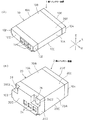
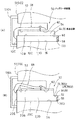
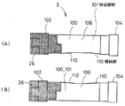
図1は実施例1で用いる第1、第2バッテリー装置の斜視図、図2はバッテリー装置の説明図、図3はバッテリー装置に貼付されるフィルムの説明図、図4は実施例1の電子機器のバッテリー収容室の構成を示す一部を破断した状態を示す斜視図、図5は第1、第2バッテリー装置がバッテリー収容室に収容された状態を示す説明図である。
本実施例では、図1(A)、(B)に示す第1バッテリー装置1、第2バッテリー装置2の厚さの異なる2種類のバッテリー装置が図4に示す単一のバッテリー収容室50に選択的に収容される。
まず、バッテリー装置について説明する。
図1(A)に示すように、第1バッテリー装置1は、ケース10と、ケース10の内部に設けられた充電池部12(図2(B))と、ケース10に設けられたバッテリー側端子14とを備えている。
図1(B)に示すように、第2バッテリー装置2は、ケース20と、ケース20の内部に設けられた充電池部22(図2(B))と、ケース20に設けられたバッテリー側端子24とを備えている。
Next, Embodiment 1 of the present invention will be described with reference to the drawings.
1 is a perspective view of the first and second battery devices used in the first embodiment, FIG. 2 is an explanatory diagram of the battery device, FIG. 3 is an explanatory diagram of a film attached to the battery device, and FIG. 4 is an electronic diagram of the first embodiment. The perspective view which shows the state which fractured | ruptured a part which shows the structure of the battery storage chamber of an apparatus, FIG. 5 is explanatory drawing which shows the state in which the 1st, 2nd battery apparatus was accommodated in the battery storage chamber.
In the present embodiment, two types of battery devices having different thicknesses of the first battery device 1 and the
First, the battery device will be described.
As shown in FIG. 1A, the first battery device 1 includes a
As shown in FIG. 1B, the
本実施例では、ケース10、20は、幅方向Wの両端に位置する側面10A、20Aと、厚さ方向Dの両端に位置する上面10B、20Bおよび下面10C、20Cと、長さ方向Lの両端に位置する前面10D、20Dおよび後面10E、20Eとを有している。
第1バッテリー装置1のケース10と、第2バッテリー装置2のケース20とは、幅と長さが等しく、かつ、厚さが第1バッテリー装置1のケース10よりも第2バッテリー装置2のケース20が大きく形成されている。
第1、第2バッテリー装置1、2に設けられたバッテリー側端子14、24は、それらの前面10D、20Dにおいてそれらの下面10C、20C、側面10A、20Aを基準とした同一の箇所に設けられ、それぞれ充電池部22に接続されている。
In the present embodiment, the
The
The battery-
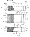
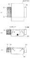
図2(A)〜(C)は第2バッテリー装置2のケース20の左側面図、平面図、右側面図を示している。
この図2を参照して第2バッテリー装置2のケース20とともに、第1バッテリー装置1のケース10の概略構成について説明する。
ケース10、20は、それぞれフレーム100を有し、フレーム100は四辺形の枠状部材101と、この枠状部材101の前部にはめ込まれた前キャップ102を有している。
そして、前面10D、20Dは前キャップ102の前面で構成され、後面10E、20Eは枠状部材101の後部104の後面で構成されている。
また、前キャップ102と後部104との間は枠状部材101の側壁106が露出しており、充電池部12は前キャップ102に取着されてそれら前キャップ102と後部104と、2つの側壁106で形成された空間に収納されている。
また、ケース10、20は、図1に示すように、前面10D、20D寄り部分と後面10E、20E寄り部分との間の前キャップ102、後部104、2つの側壁106上の全周にフィルム202が巻装されて取着されている。
より詳細に説明すると、フィルム202は絶縁性を有し、上フィルム204と下フィルム206により構成されている。
そして、図3(A)、(B)に示すように、まず、上フィルム204が、前キャップ102と後部104との間で上方に露出する充電池部12部分および側壁106部分を覆うように貼着され、さらに充電池部12の下面の両側部分に貼着される。次いで、充電池部12(22)の下面の両側部分に貼着された上フィルム204部分、および、前キャップ102と後部104との間で下方に露出する充電池部12(22)の下面部分を覆うように下フィルム206が貼着されている。
このように大きさ形状が異なるものの第1バッテリー装置1と第2バッテリー装置2のケース10、20は、それぞれフレーム100とフィルム202で構成されている。
2A to 2C show a left side view, a plan view, and a right side view of the
A schematic configuration of the
Each of the
The
Further, the
Further, as shown in FIG. 1, the
More specifically, the
Then, as shown in FIGS. 3A and 3B, first, the
The
第2バッテリー装置2のケース20の前面20Dには、幅方向Wに間隔をおいて係合凹部26、28が設けられている。
一方の係合凹部26は、2つの側面20Aのうちの一方の側面20Aおよび前面20D並びに上面20Bに開放状に形成されている。
他方の係合凹部28は、2つの側面20Aのうちの他方の側面20Aおよび前面20D並びに上面20Bに開放状に形成されている。
各係合凹部26、28を形成する前キャップ202の壁部で下面20C寄りの箇所は上面20Bおよび下面20Cに平行な平坦面2402、2602として形成されている。
そして、ケース20の下面から平坦面2402、2602までの寸法と、第1バッテリー装置1のケース10の下面10Cから上面10Bまでの寸法は等しく形成されている。
One
The
The portions near the
The dimension from the lower surface of the
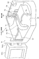
次に電子機器のバッテリー収容室について説明する。
図4に示すように、バッテリー収容室50は電子機器51の筐体5102に設けられている。
バッテリー収容室50は、筐体5102の後面に開口する挿脱用開口52を有し、この挿脱用開口52は開閉蓋5104により開閉される。
バッテリー収容室50は、第1、第2バッテリー装置1、2のケース10、20の幅方向Wの両端の側面10A、20Aに当接可能な側壁54と、ケース10、20の下面10C、20Cに当接可能な当接壁56と、ケース10、20の長さに対応する深さに設けられた奥壁58と、第2バッテリー装置2のケース20の厚さに対応する高さに設けられた上壁60とを有している。
奥壁58には、第1、第2バッテリー装置1、2が挿脱用開口52から長さ方向Lを前記深さ方向に平行させ挿入された状態で前記バッテリー側端子14、24に接触する収容室側端子62が設けられている。
Next, the battery housing chamber of the electronic device will be described.
As shown in FIG. 4, the
The
The
The first and
奥壁58の幅方向に間隔を置いた箇所には、係合凸部64、66が挿脱用開口52に向けて突出形成されている。
係合凸部64、66は、第1バッテリー装置1のケース10の上面10Bの前縁に係合することで第1バッテリー装置1のケース10の下面10Cを当接壁56に当て付けた状態に保持し、かつ、第2バッテリー装置2のケース20の係合凹部26、28に係合することで第2バッテリー装置2のケース20の下面20Cを当接壁56に当て付けた状態に保持するように構成されている。
より詳細には、各係合凸部64、66が当接壁56に臨む下面64A、66Aが、第1バッテリー装置1のケース10の上面10Bの前縁に係合することで第1バッテリー装置1を当接壁56に当て付けた状態に保持し、かつ、各係合凸部64、66の下面64A、66Aが第2バッテリー装置2のケース20の係合凹部26、28の平坦面2602、2802に係合することで第2バッテリー装置2を当接壁56に当て付けた状態に保持するように構成されている。
Engaging
The engagement
More specifically, the first battery device is configured such that the
また、挿脱用開口52を構成する上壁60部分には押え部材68が設けられており、押え部材68の先端の係合部6802は、第1バッテリー装置1および第2バッテリー装置2の双方のケース10、20の後面10E、20Eの上縁に係合し、バッテリー収容室に収用された第1、第2バッテリー装置1、2を奥壁58方向に付勢し、バッテリー側端子14、24を収容室側端子62に接触した状態に保持するように構成されている。本実施例では、押え部材68は可撓性を有する弾性部材によって構成され、バッテリー装置を挿脱する際に指によって持ち上げられる。
なお、バッテリー収容室に収容された第1、第2バッテリー装置1、2を奥壁58方向に付勢し、バッテリー側端子14、24を収容室側端子62に接触した状態に保持する構造としては従来公知の様々な機構が採用可能であり、この機構は実施例のように筐体側に設けてもよいし、開閉蓋5104に設けてもよい。
In addition, a pressing
The first and
次に第1、第2バッテリー装置1、2のバッテリー収容室50への収容、取り出しについて説明する。
バッテリー収容室50に第1バッテリー装置1を収容する際には、図5(A)に示すように、押え部材68の係合部6802を指で挿脱用開口52から上方に変位させた状態とし、第1バッテリー装置1のバッテリー側端子14をバッテリー収容室50の挿脱用開口52に臨ませ、その長さ方向Lをバッテリー収容室50の深さ方向に平行させ、挿入する。これにより、第1バッテリー装置1の下面10Cはバッテリー収容室50の当接壁56に案内され、第1バッテリー装置1の両側面10Aはバッテリー収容室50の両側壁54に案内されバッテリー収容室50に挿入される。
押え部材68から指を外すと、係合部6802は第1バッテリー装置1の上面10Bに接触した状態となり、さらなる第1バッテリー装置1の挿入により第1バッテリー装置1の上面10Bの前面10D寄りの箇所にバッテリー収容室50の2つの係合凸部64、66が係合し、第1バッテリー装置1のケース10の下面10Cが当接壁56に当て付けた状態に保持される。
さらなる第1バッテリー装置1の挿入によりバッテリー側端子14が収容室側端子62に接触し、この状態で押え部材68の係合部6802が上面10Bの後縁に係合し、バッテリー側端子14が収容室側端子62に接触した状態に保持され、第1バッテリー装置1がバッテリー収容室50に収容される。
一方、バッテリー収容室50から第1バッテリー装置1を取り出す際には、押え部材68の係合部6802を指で挿脱用開口52から上方に変位させ、第1バッテリー装置1を指で把持して後方へ抜き出すことにより、第1バッテリー装置1がバッテリー収容室50から取り出される。
Next, accommodation and removal of the first and
When the first battery device 1 is accommodated in the
When the finger is removed from the pressing
When the first battery device 1 is further inserted, the
On the other hand, when the first battery device 1 is taken out from the
バッテリー収容室50に第2バッテリー装置2を収容する際には、図5(B)に示すように、押え部材68の係合部6802を指で挿脱用開口52から上方に変位させた状態とし、第2バッテリー装置2のバッテリー側端子24をバッテリー収容室50の挿脱用開口52に臨ませ、その長さ方向Lをバッテリー収容室50の深さ方向に平行させ、挿入する。これにより、第2バッテリー装置2の下面20Cはバッテリー収容室50の当接壁56に案内され、第2バッテリー装置2の上面20Bはバッテリー収容室50の上壁60に案内され、第1バッテリー装置2の両側面20Aはバッテリー収容室50の両側壁54に案内されバッテリー収容室50に挿入される。
押え部材68から指を外すと、係合部6802は第2バッテリー装置2の上面20Bに接触した状態となり、さらなる第2バッテリー装置2の挿入により第2バッテリー装置2の各係合凹部26、28の平坦面2602、2802にバッテリー収容室50の2つの係合凸部64、66の下面64A、66Aが係合し、第2バッテリー装置2のケース20の下面20Cが当接壁56に当て付けた状態に保持される。
さらなる第2バッテリー装置2の挿入によりバッテリー側端子24が収容室側端子62に接触し、この状態で押え部材68の係合部6802が上面20Bの後縁に係合し、バッテリー側端子14が収容室側端子62に接触した状態に保持され、第2バッテリー装置2がバッテリー収容室50に収容される。
一方、バッテリー収容室50から第2バッテリー装置2を取り出す際には、押え部材68の係合部6802を指で挿脱用開口52から上方に変位させ、第2バッテリー装置2を指で把持して後方へ抜き出すことにより、第2バッテリー装置2がバッテリー収容室50から取り出される。
When the
When the finger is removed from the pressing
When the
On the other hand, when the
したがって、本実施例によれば、厚さの異なる2種類の第1、第2バッテリー装置1、2を同一のバッテリー収容室50に選択的に収容することができ、例えば、使用用途や使用目的に応じて容量の異なるバッテリー装置を使い分けることができ、使い勝手を向上する上で有利となる。
また、実施例では、係合凸部64、66および係合凹部24、26を幅方向Wに間隔をおいて複数(2つ)設けたので、第1、第2バッテリー装置1、2のバッテリー収容室50への収容状態を安定させる上で有利となる。
また、実施例では、バッテリー収容室50に、第2バッテリー装置2の上面20Bに当接可能な上壁60が設けられているので、第2バッテリー装置2のバッテリー収容室50への収容状態を安定させる上で有利となる。
Therefore, according to the present embodiment, two types of first and
In the embodiment, since the
Further, in the embodiment, since the
次に実施例2について説明する。
実施例2が実施例1と異なるのは押え部材78が上下方向にスライド可能に設けられている点である。
図6は実施例2におけるバッテリー収容室の構成を示す説明図である。
図6に示すように、押え部材78は上下方向に直線状に延在し下端にケース10、20の後面10E、20E上部に係合する係合凹部7802が設けられている。
押え部材78は、挿抜用開口52に臨む筐体5102部分に配設されている。
押え部材78は、該押え部材78に設けられたガイド溝7810に筐体5102から突設されたピン5110が係合することで上下方向にスライド可能に設けられ、下端の係合凹部7802が当接壁56方向に向けて付勢部材7804で常時付勢されており、指によって押え部材78を上方に動かすことで係合凹部7802が挿抜用開口52から退避するようになっている。
したがって、第1バッテリー装置1、第2バッテリー装置2の挿脱の際には、実施例1と同様に指により押え部材78を挿脱用開口52から退避させることが行われる。
また、図6において二点鎖線で示すように、第1バッテリー装置1がバッテリー収容室50に挿入されると、押え部材78の係合凹部7802が第1バッテリー装置1のケース10の上面10Bの上縁に係合することで、第1バッテリー装置1のバッテリー側端子14が収容室側端子62に接触した状態に保持される。
また、図6において実線で示すように、第2バッテリー装置2がバッテリー収容室50に挿入されると、押え部材78の係合凹部7802が第2バッテリー装置2のケース20の上面20Bの上縁に係合することで、第2バッテリー装置2のバッテリー側端子24が収容室側端子62に接触した状態に保持される。
このような実施例2においても実施例1と同様の作用効果を奏することはもちろんである。
Next, Example 2 will be described.
The second embodiment differs from the first embodiment in that a pressing
FIG. 6 is an explanatory diagram showing the configuration of the battery housing chamber in the second embodiment.
As shown in FIG. 6, the pressing
The holding
The
Therefore, when the first battery device 1 and the
Further, as shown by a two-dot chain line in FIG. 6, when the first battery device 1 is inserted into the
Further, as shown by a solid line in FIG. 6, when the
Needless to say, the second embodiment also has the same effects as the first embodiment.
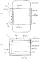
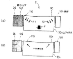
次にフィルム202の貼付について説明する。
本実施例では、図2(A)、(B)に示すように、第1、第2バッテリー装置1、2は、側方から見て前キャップ102と各側壁106の上縁との間にそれぞれ前キャップ102が高く側壁106の上縁が低い段差Dが形成され、かつ、後部104と各側壁106の上縁との間にそれぞれ後部104が高く各側壁106の上縁が低い段差Dが形成されている。
上述したように4つの段差Dが形成された状態で、図7(A)、(B)に示すように、前面10D、20D寄り部分と後面10E、20E寄り部分との間の前キャップ102、後部104、2つの側壁106上に上フィルム204を貼り付け、上フィルム204の幅方向の両側に下方(矢印F方向)の引っ張り力を加えると、図7(C)に示すように、上フイルム204が各段差Dに当て付けられた部分に応力F1、F2が集中して生じ、これにより上フィルム204にシワが発生してしまい、美観を損ねる不都合が発生する。
Next, sticking of the
In this embodiment, as shown in FIGS. 2A and 2B, the first and
With the four steps D formed as described above, as shown in FIGS. 7A and 7B, the
このようなシワの発生を防止するために、図8(A)、(B)に示すように、前キャップ102に臨む側壁106の上縁部分に前キャップ102との段差Dを解消する上方に突出した傾斜部108が設けられるととともに、後部104に臨む側壁106の上縁部分に後部104との段差Dを解消する上方に突出した傾斜部110が設けられている。すなわち、傾斜部110は、フレーム100の長さ方向の中間部から前キャップ102または後部104に至るにつれて次第にフレーム100からの突出量が次第に多くなり前キャップ102または後部104に連続状につながるように形成されている。
このような構成によれば、図9に示すように、前面10D、20D寄り部分と後面10E、20E寄り部分との間の前キャップ102、後部104、2つの側壁106上に上フィルム204を貼り付け、上フィルム204の幅方向の両側に下方(矢印F方向)の引っ張り力を加えたとしても、上フィルム204は各傾斜部110に当て付けられるため、この当て付けられた部分に発生する応力F1、F2は分散し、これにより上フィルム204にシワが発生することが防止され、美観を向上させる上で有利となる。
In order to prevent the occurrence of such wrinkles, as shown in FIGS. 8A and 8B, the upper edge portion of the
According to such a configuration, as shown in FIG. 9, the
1……第1バッテリー装置、2……第2バッテリー装置、10、20……ケース、10A、20A……側面、10B、20B……上面、10C、20C……下面、10D、20D……前面、10E、20E……後面、12、22……充電池部、14、24……バッテリー側端子、26、28……係合凹部、50……バッテリー収容室、52……挿脱用開口、54……側壁、56……当接壁、58……奥壁、62……収容室側端子、64、66……係合凸部、68、78……押え部材。
DESCRIPTION OF SYMBOLS 1 ... 1st battery device, 2 ... 2nd battery device, 10, 20 ... Case, 10A, 20A ... Side surface, 10B, 20B ... Upper surface, 10C, 20C ... Lower surface, 10D, 20D ...
Claims (5)
前記バッテリー収容室は、挿脱用開口と、前記ケースの幅方向の両端の側面に当接可能な2つの側壁と、前記ケースの下面に当接可能な当接壁と、前記ケースの長さに対応する深さに設けられた奥壁を有し、
前記奥壁に、前記バッテリー装置が前記挿脱用開口から前記長さ方向を前記深さ方向に平行させ挿入された状態で前記バッテリー側端子に接触する収容室側端子と、前記第1バッテリー装置のケースの上面に係合することで前記第1バッテリー装置のケースの下面を前記当接壁に当て付けた状態に保持し、かつ、前記第2バッテリー装置のケースの前面に設けられた係合凹部に係合することで前記第2バッテリー装置のケースの下面を前記当接壁に当て付けた状態に保持する係合凸部が設けられ、
前記バッテリー収容室に挿入された前記第1バッテリー装置または第2バッテリー装置のケースの後面に係合し前記バッテリー側端子を前記収容室側端子に接触した状態に保持する押え部材が設けられている、
ことを特徴とする電子機器。 A case having side surfaces positioned at both ends in the width direction, upper and lower surfaces positioned at both ends in the thickness direction, and a front surface and a rear surface positioned at both ends in the length direction, and a rechargeable battery unit provided in the case A first battery device provided with a battery-side terminal provided on the front surface of the case and connected to the rechargeable battery unit; and a second battery device having the same width and length as the first battery device and a large thickness. An electronic apparatus having a battery storage chamber in which two types of battery devices having different thicknesses are selectively stored,
The battery housing chamber includes an insertion / removal opening, two side walls that can contact the side surfaces of both ends in the width direction of the case, a contact wall that can contact the lower surface of the case, and the length of the case Has a back wall provided at a depth corresponding to
A storage chamber-side terminal that contacts the battery-side terminal in a state where the battery device is inserted into the back wall with the length direction parallel to the depth direction from the insertion / removal opening, and the first battery device By engaging with the upper surface of the case, the lower surface of the case of the first battery device is held against the abutting wall, and the engagement is provided on the front surface of the case of the second battery device. An engagement convex portion is provided to hold the lower surface of the case of the second battery device in contact with the contact wall by engaging with the concave portion,
A pressing member is provided that engages a rear surface of the case of the first battery device or the second battery device inserted into the battery housing chamber and holds the battery side terminal in contact with the housing chamber side terminal. ,
An electronic device characterized by that.
Priority Applications (1)
| Application Number | Priority Date | Filing Date | Title |
|---|---|---|---|
| JP2004102644A JP4721037B2 (en) | 2004-03-31 | 2004-03-31 | Electronics |
Applications Claiming Priority (1)
| Application Number | Priority Date | Filing Date | Title |
|---|---|---|---|
| JP2004102644A JP4721037B2 (en) | 2004-03-31 | 2004-03-31 | Electronics |
Publications (2)
| Publication Number | Publication Date |
|---|---|
| JP2005293860A true JP2005293860A (en) | 2005-10-20 |
| JP4721037B2 JP4721037B2 (en) | 2011-07-13 |
Family
ID=35326584
Family Applications (1)
| Application Number | Title | Priority Date | Filing Date |
|---|---|---|---|
| JP2004102644A Expired - Fee Related JP4721037B2 (en) | 2004-03-31 | 2004-03-31 | Electronics |
Country Status (1)
| Country | Link |
|---|---|
| JP (1) | JP4721037B2 (en) |
Cited By (3)
| Publication number | Priority date | Publication date | Assignee | Title |
|---|---|---|---|---|
| JP2013239421A (en) * | 2012-05-24 | 2013-11-28 | Sony Corp | Battery pack |
| US9799930B2 (en) | 2012-05-15 | 2017-10-24 | Sony Corporation | Battery pack |
| CN109860458A (en) * | 2016-12-28 | 2019-06-07 | 深圳市大疆灵眸科技有限公司 | Power supply mould group and holder |
Citations (3)
| Publication number | Priority date | Publication date | Assignee | Title |
|---|---|---|---|---|
| JPS61146865A (en) * | 1984-12-18 | 1986-07-04 | 株式会社アルファ技研 | Prevention of dispersion of knitted and bundled article |
| JPS62129763A (en) * | 1985-07-27 | 1987-06-12 | テ−プインプ リミテツド | Inertia detector |
| JPH08162081A (en) * | 1994-12-08 | 1996-06-21 | Sharp Corp | Battery connecting device |
Family Cites Families (2)
| Publication number | Priority date | Publication date | Assignee | Title |
|---|---|---|---|---|
| JPH0334048Y2 (en) * | 1985-03-01 | 1991-07-18 | ||
| JPH0525174Y2 (en) * | 1986-02-07 | 1993-06-25 |
-
2004
- 2004-03-31 JP JP2004102644A patent/JP4721037B2/en not_active Expired - Fee Related
Patent Citations (3)
| Publication number | Priority date | Publication date | Assignee | Title |
|---|---|---|---|---|
| JPS61146865A (en) * | 1984-12-18 | 1986-07-04 | 株式会社アルファ技研 | Prevention of dispersion of knitted and bundled article |
| JPS62129763A (en) * | 1985-07-27 | 1987-06-12 | テ−プインプ リミテツド | Inertia detector |
| JPH08162081A (en) * | 1994-12-08 | 1996-06-21 | Sharp Corp | Battery connecting device |
Cited By (5)
| Publication number | Priority date | Publication date | Assignee | Title |
|---|---|---|---|---|
| US9799930B2 (en) | 2012-05-15 | 2017-10-24 | Sony Corporation | Battery pack |
| US10797362B2 (en) | 2012-05-15 | 2020-10-06 | Sony Corporation | Battery pack |
| US11462776B2 (en) | 2012-05-15 | 2022-10-04 | Sony Corporation | Battery pack |
| JP2013239421A (en) * | 2012-05-24 | 2013-11-28 | Sony Corp | Battery pack |
| CN109860458A (en) * | 2016-12-28 | 2019-06-07 | 深圳市大疆灵眸科技有限公司 | Power supply mould group and holder |
Also Published As
| Publication number | Publication date |
|---|---|
| JP4721037B2 (en) | 2011-07-13 |
Similar Documents
| Publication | Publication Date | Title |
|---|---|---|
| KR100959728B1 (en) | Battery device | |
| JP2001285431A (en) | Built-in battery retaining structure for portable equipment | |
| US7123886B2 (en) | Handheld mobile phone with a detachable battery pack | |
| JP4721037B2 (en) | Electronics | |
| JP4665408B2 (en) | Battery compartment structure of electronic equipment | |
| JP2009158401A (en) | Electronic device | |
| JP4773136B2 (en) | Battery holder | |
| JP2001043841A (en) | Battery storing mechanism and battery pack for portable electronic equipment | |
| JP2007299552A (en) | Portable terminal device, and its housing | |
| WO2012132300A1 (en) | Electronic device | |
| JPH1069896A (en) | Battery pack holding device | |
| JP4029547B2 (en) | Button-type battery holding device | |
| JPH09306457A (en) | Battery storage device | |
| JPH0738934A (en) | Battery container structure for electronic device | |
| JPH10208719A (en) | Cover of battery housing part | |
| JP4134970B2 (en) | Electronic device charger | |
| JP4936704B2 (en) | Pack battery | |
| JPH04349345A (en) | Holder for battery case and battery case loaded therein | |
| JP2024041770A (en) | information terminal | |
| JP2004288424A (en) | Cell storing method and cell storing device | |
| JP2009295445A (en) | Portable equipment | |
| JPH10144276A (en) | Coin type battery housing structure | |
| JPH0588151U (en) | Plate battery charger | |
| JPH0528984A (en) | Battery | |
| JP2009026582A (en) | Battery pack storage structure for portable electronic device |
Legal Events
| Date | Code | Title | Description |
|---|---|---|---|
| A621 | Written request for application examination |
Free format text: JAPANESE INTERMEDIATE CODE: A621 Effective date: 20060828 |
|
| RD02 | Notification of acceptance of power of attorney |
Free format text: JAPANESE INTERMEDIATE CODE: A7422 Effective date: 20090812 |
|
| RD04 | Notification of resignation of power of attorney |
Free format text: JAPANESE INTERMEDIATE CODE: A7424 Effective date: 20091013 |
|
| A977 | Report on retrieval |
Free format text: JAPANESE INTERMEDIATE CODE: A971007 Effective date: 20091203 |
|
| A131 | Notification of reasons for refusal |
Free format text: JAPANESE INTERMEDIATE CODE: A131 Effective date: 20100401 |
|
| A521 | Request for written amendment filed |
Free format text: JAPANESE INTERMEDIATE CODE: A523 Effective date: 20100520 |
|
| A01 | Written decision to grant a patent or to grant a registration (utility model) |
Free format text: JAPANESE INTERMEDIATE CODE: A01 Effective date: 20110310 |
|
| A01 | Written decision to grant a patent or to grant a registration (utility model) |
Free format text: JAPANESE INTERMEDIATE CODE: A01 |
|
| A61 | First payment of annual fees (during grant procedure) |
Free format text: JAPANESE INTERMEDIATE CODE: A61 Effective date: 20110323 |
|
| FPAY | Renewal fee payment (event date is renewal date of database) |
Free format text: PAYMENT UNTIL: 20140415 Year of fee payment: 3 |
|
| FPAY | Renewal fee payment (event date is renewal date of database) |
Free format text: PAYMENT UNTIL: 20140415 Year of fee payment: 3 |
|
| R250 | Receipt of annual fees |
Free format text: JAPANESE INTERMEDIATE CODE: R250 |
|
| LAPS | Cancellation because of no payment of annual fees |