JP2005293552A - Grid canvas - Google Patents
Grid canvas Download PDFInfo
- Publication number
- JP2005293552A JP2005293552A JP2005033505A JP2005033505A JP2005293552A JP 2005293552 A JP2005293552 A JP 2005293552A JP 2005033505 A JP2005033505 A JP 2005033505A JP 2005033505 A JP2005033505 A JP 2005033505A JP 2005293552 A JP2005293552 A JP 2005293552A
- Authority
- JP
- Japan
- Prior art keywords
- grid
- canvas
- layout
- defining
- bounding box
- Prior art date
- Legal status (The legal status is an assumption and is not a legal conclusion. Google has not performed a legal analysis and makes no representation as to the accuracy of the status listed.)
- Pending
Links
- 238000000034 method Methods 0.000 claims description 32
- 230000006870 function Effects 0.000 claims description 6
- 230000007246 mechanism Effects 0.000 description 11
- 238000004891 communication Methods 0.000 description 7
- 230000003287 optical effect Effects 0.000 description 7
- 238000012545 processing Methods 0.000 description 6
- 238000010586 diagram Methods 0.000 description 5
- 238000004513 sizing Methods 0.000 description 5
- 230000006399 behavior Effects 0.000 description 4
- 238000013461 design Methods 0.000 description 4
- 230000005055 memory storage Effects 0.000 description 4
- 230000002093 peripheral effect Effects 0.000 description 4
- 230000005540 biological transmission Effects 0.000 description 3
- 230000006855 networking Effects 0.000 description 3
- 238000004364 calculation method Methods 0.000 description 2
- 230000008859 change Effects 0.000 description 2
- 230000009467 reduction Effects 0.000 description 2
- 239000007787 solid Substances 0.000 description 2
- 238000007792 addition Methods 0.000 description 1
- 238000013459 approach Methods 0.000 description 1
- 238000010276 construction Methods 0.000 description 1
- 238000009429 electrical wiring Methods 0.000 description 1
- 238000005516 engineering process Methods 0.000 description 1
- 238000000802 evaporation-induced self-assembly Methods 0.000 description 1
- 238000005259 measurement Methods 0.000 description 1
- 238000012986 modification Methods 0.000 description 1
- 230000004048 modification Effects 0.000 description 1
- 239000013307 optical fiber Substances 0.000 description 1
- 230000008569 process Effects 0.000 description 1
- 238000012546 transfer Methods 0.000 description 1
- 230000007723 transport mechanism Effects 0.000 description 1
Images
Classifications
-
- G—PHYSICS
- G06—COMPUTING; CALCULATING OR COUNTING
- G06T—IMAGE DATA PROCESSING OR GENERATION, IN GENERAL
- G06T11/00—2D [Two Dimensional] image generation
- G06T11/60—Editing figures and text; Combining figures or text
-
- G—PHYSICS
- G06—COMPUTING; CALCULATING OR COUNTING
- G06T—IMAGE DATA PROCESSING OR GENERATION, IN GENERAL
- G06T3/00—Geometric image transformations in the plane of the image
- G06T3/40—Scaling of whole images or parts thereof, e.g. expanding or contracting
-
- G—PHYSICS
- G06—COMPUTING; CALCULATING OR COUNTING
- G06F—ELECTRIC DIGITAL DATA PROCESSING
- G06F9/00—Arrangements for program control, e.g. control units
- G06F9/06—Arrangements for program control, e.g. control units using stored programs, i.e. using an internal store of processing equipment to receive or retain programs
- G06F9/44—Arrangements for executing specific programs
- G06F9/451—Execution arrangements for user interfaces
Landscapes
- Engineering & Computer Science (AREA)
- Theoretical Computer Science (AREA)
- Software Systems (AREA)
- General Physics & Mathematics (AREA)
- Physics & Mathematics (AREA)
- General Engineering & Computer Science (AREA)
- Human Computer Interaction (AREA)
- Processing Or Creating Images (AREA)
- Fencing (AREA)
- Catching Or Destruction (AREA)
- Baking, Grill, Roasting (AREA)
- Housing For Livestock And Birds (AREA)
- User Interface Of Digital Computer (AREA)
Abstract
Description
本発明は、一般にコンピュータグラフィックスの分野に関し、より詳細には、本発明は、ディスプレイ上でのオブジェクトのレイアウトに関する。 The present invention relates generally to the field of computer graphics, and more particularly to the layout of objects on a display.
ユーザインターフェース要素(ウィンドウ領域、コントロールなど)のレイアウトを設計する時に、多くの場合デザイナーキャンバスが使用され、要素(本明細書ではオブジェクトとも称する)がキャンバス上に置かれる。しかし、アプリケーションが構築され、キャンバスによって覆われた領域のサイズが変更される時に、インテリジェントな形で全ての要素のサイズを変更させることが困難になる。従来の手法は、設計者にとって不完全であり、複雑であり、または分かり難い傾向にある。 When designing the layout of user interface elements (window areas, controls, etc.), a designer canvas is often used and elements (also referred to herein as objects) are placed on the canvas. However, when an application is built and the area covered by the canvas is resized, it becomes difficult to intelligently resize all elements. Conventional approaches tend to be incomplete, complex, or difficult to understand for designers.
設計者がサイズ変更を行うコードを記述せずにサイズを変更するよう、レイアウトを設計することが望ましい。従来、知的にサイズを変更するアプリケーションレイアウトは、不完全な機構、過度に複雑な機構、または設計者がアクセスできないコードによって作成されていた。 It is desirable to design the layout so that the designer can change the size without writing code for changing the size. Traditionally, intelligently resizing application layouts have been created with imperfect mechanisms, overly complex mechanisms, or code that is not accessible to the designer.
従来の機構は、キャンバススタイルのレイアウトである。この種のレイアウトは、掲示板への書き込みのと同様に、新たな要素を仮付けできる領域を提供する。掲示板と同様に、オブジェクトは、プログラマが明示的に動かさない限り、配置後は静止している。 The conventional mechanism is a canvas style layout. This type of layout provides an area where a new element can be temporarily attached, similar to writing on a bulletin board. Similar to bulletin boards, objects remain stationary after placement unless the programmer explicitly moves them.
別の従来の機構は、プロポーショナル−リサイズレイアウトである。このレイアウトは、掲示板全体が後に、比例して引き延ばされることができる単一の画像であると見なされることを除いて、キャンバス−スタイルレイアウトと同一である。このタイプのレイアウトは、画面サイズの拡大に伴って大きくなるよう設計された固定機能のユーザインターフェース(例えば単純なゲーム)については許容されるが、より高い情報密度で表示すために画面をより高度な利用が可能な場合には好ましくない(例えばワードプロセッシングディスプレイ)。 Another conventional mechanism is a proportional-resize layout. This layout is identical to the canvas-style layout except that the entire bulletin board is later considered a single image that can be stretched proportionally. This type of layout is acceptable for fixed function user interfaces (eg simple games) designed to grow as screen size increases, but the screen is more advanced to display at higher information densities. It is not preferable when it is possible to use the system (for example, word processing display).
テーブルスタイルのレイアウトもまた、別の従来のレイアウト機構である。このレイアウトは、HTMLに見られるレイアウトに類似する。使用可能なスペースは、個別のセルに切り分けられ、各セルが、そのコンテンツのコンテナである。しばしば、所望のレイアウトを作成するために、より大きい要素(例えば画像)をセルの間で分割しなければならない。 Table style layout is also another conventional layout mechanism. This layout is similar to the layout found in HTML. The available space is cut into individual cells, each cell being a container for its content. Often, larger elements (eg, images) must be divided between cells to create the desired layout.
別種のレイアウト機構には、アタッチメント−ベースのレイアウトがある。このレイアウトでは、各オブジェクトが、キャンバス側全体にそれ自体を「取り付ける」ことを許可され、例えば左および右に取り付ける場合、その幅は、アプリケーションのサイズが変更される時に固定された余白を保ちながら変更される。 Another type of layout mechanism is an attachment-based layout. In this layout, each object is allowed to “attach” itself to the entire canvas side, eg when attached to the left and right, its width remains fixed when the application is resized. Be changed.
Java(登録商標)のGridBagなどの「アドバンスト」レイアウトも周知である。GridBagでは、(スパニング情報および余白を含む)各子(child)への位置決め情報および全ての子データに対する推論を割り当て、レイアウトする。GridBagコンテナ自体は、情報を有しない。このレイアウトは、前述のレイアウトより機能し得るが、細かな設定が極端に難しい(すなわち、明瞭で単純なユーザインターフェースで示すのが難しい)。 “Advanced” layouts such as Java® GridBag are also well known. In GridBag, allocation information for each child (including spanning information and margins) and inference for all child data are allocated and laid out. The GridBag container itself has no information. This layout can function more than the previous layout, but it is extremely difficult to fine-tune (ie, difficult to show with a clear and simple user interface).
「スプリングアンドストラット(springs and struts)」は、従来のレイアウトであり、他の座標からの式として各オブジェクト座標を効果的に定義することができる。例えば、「スプリングアンドストラット」環境では、2つの要素が必ず10画素離れているように構成することができる。当初は表現力があるが、この機構は、特にランタイムが最終的にタスクとして不適当になる極端に入り組んだ再計算要件を有するので、すぐに行き詰る。 “Springs and struts” is a conventional layout, and each object coordinate can be effectively defined as an expression from other coordinates. For example, in a “spring and strut” environment, the two elements can be configured to be 10 pixels apart. Although initially expressive, this mechanism quickly gets stuck, especially because it has extreme recalculation requirements that make the runtime ultimately unsuitable as a task.
前述の課題を考慮すると、従来技術の制限および短所を克服するシステムおよび方法の必要性がある。 In view of the foregoing problems, there is a need for a system and method that overcomes the limitations and disadvantages of the prior art.
本発明は、簡易で知的にサイズを変更するレイアウトを対象とする。要素(すなわちオブジェクト)が、別々に定義される行および列の罫線(gridline)の仮想グリッドに取り付けられる。オブジェクトとグリッドとの間の関係は、双方向であり、その結果、一方(罫線またはオブジェクト)の移動が、他方(オブジェクトまたはグリッド)に影響するようになっている。つまり、オブジェクトの拡大/縮小によって、罫線が押され、罫線の移動によって、オブジェクトが拡大/縮小される。仮想グリッドは、さらなる柔軟性を有し、オブジェクトの前後に作成することができる。子オブジェクトは、それ自体の仮想グリッドを有することができ、これによって、所望のきめの細かい制御が可能になる。 The present invention is directed to a simple and intelligent layout for changing the size. Elements (ie objects) are attached to a virtual grid of separately defined row and column gridlines. The relationship between the object and the grid is bi-directional, so that the movement of one (ruled line or object) affects the other (object or grid). That is, the ruled line is pushed by the enlargement / reduction of the object, and the object is enlarged / reduced by the movement of the ruled line. Virtual grids have additional flexibility and can be created before and after an object. A child object can have its own virtual grid, which allows the fine-grained control desired.
本発明の追加の特徴および利点は、添付の図面を参照して行う以下の例示的な実施形態の詳細な説明から明らかになる。 Additional features and advantages of the invention will be made apparent from the following detailed description of illustrative embodiments that proceeds with reference to the accompanying drawings.
前述の概要ならびに以下の好ましい実施形態の詳細な説明は、添付の図面と共に読まれる時に最もよく理解される。本発明の例示のために、図面に、本発明の例示的な構成を示すが、本発明は、開示される特定の方法および手段に制限されない。 The foregoing summary, as well as the following detailed description of the preferred embodiments, is best understood when read in conjunction with the accompanying drawings. For the purpose of illustrating the invention, there are shown in the drawings exemplary constructions of the invention; however, the invention is not limited to the specific methods and instrumentalities disclosed.
本発明は、オブジェクトが、別々に定義される行および列の罫線の仮想グリッドに取り付けられるレイアウトを対象とする。オブジェクトとグリッドの間の関係は、双方向であり、その結果、オブジェクトの拡大/縮小によって、罫線が押され、罫線の移動によって、オブジェクトが拡大/縮小される。そのようなレイアウト機構を、本明細書では「グリッドキャンバス」レイアウト機構と呼ぶ。 The present invention is directed to a layout in which objects are attached to a virtual grid of separately defined row and column rules. The relationship between the object and the grid is bi-directional. As a result, the ruled line is pushed by the enlargement / reduction of the object, and the object is enlarged / reduced by the movement of the ruled line. Such a layout mechanism is referred to herein as a “grid canvas” layout mechanism.
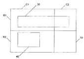
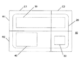
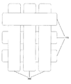
例示的なグリッドキャンバスを、図1に示す。グリッドキャンバスレイアウト機構は、親と子の間の協力である。親10は、事実上キャンバスであり、その上にオブジェクト30および40を任意の位置に描くことができ、オブジェクトは、配置された位置に留まる。いつでも、グリッドキャンバス10を望みの個数の行Rおよび列Cに分割することができる。グリッドキャンバスの各子は、グリッド境界ボックスをそのボックスに対する余白と共に維持する。例えば、オブジェクト30のグリッド境界ボックスは、行R1の全て(すなわち、R1C1:R1C2)である。余白設定によって、ボックスの境界からの適当なオフセットを使用する、グリッド境界ボックス内の「アタッチメント」の複数の種類が可能になる。行Rおよび列C自体は、グリッドキャンバス親10によって保持され、従来の方法でサイズを指定することができる(例えば、固定サイズ、パーセントサイズ、自動サイズ、加重サイズ)。
An exemplary grid canvas is shown in FIG. The grid canvas layout mechanism is cooperation between parents and children. The
本発明では、絵は、位置だけを表す仮想セルに分割される。したがって、例えば、オブジェクト30は、各々を個別に移動することを必要とする複数のセルに分割される必要はない。そうではなく、オブジェクト30は、基礎になるグリッドキャンバス10上の複数の仮想セルにまたがる。さらに、オブジェクトは、重複することができる。罫線は、仮想的であり、座標系として働き、仮想セルは、単に、座標系の現れである。本発明では、罫線に関して配置されなければならない場所の子セルの依存性を分割する。
In the present invention, the picture is divided into virtual cells that represent only the position. Thus, for example, the
本発明は、行および列で子セルを計算し、配置することができるユーザインターフェースパネルで実施することができる。子は、パネルまたはコントロールなど、任意のオブジェクトとすることができる。行および列の罫線の交差が、スロットのグリッドを形成する。子またはオブジェクトは、複数の隣接するグリッドスロットを占めることができる(例えば、オブジェクトq30は、行R1、列C1と、行R1、列C2とによって定義されるスロットまたはセルを占める)。オブジェクトのレイアウト挙動は、それがまたがる行および列の設定によって決定される。例えば、対応する列の画素幅の値および対応する行の画素高さの値を指定することによって、グリッドスロットに固定サイズを割り当てることができる。列幅は、それにまたがる子の所望の幅に関して計算することができる。行に、残りの使用可能なスペースの比率を割り当てることができる。オブジェクトは、重複することができる。というのは、複数の子が、レイアウトスロットの同一のサブセットを占めることができるからである(例えば、図5のオブジェクト20および30を参照されたい)。
The present invention can be implemented with a user interface panel that can calculate and arrange child cells in rows and columns. A child can be any object, such as a panel or control. The intersection of row and column rules forms a grid of slots. A child or object can occupy multiple adjacent grid slots (eg, object q30 occupies a slot or cell defined by row R1, column C1 and row R1, column C2). The layout behavior of an object is determined by the settings of the rows and columns it spans. For example, a fixed size can be assigned to a grid slot by specifying the pixel width value of the corresponding column and the pixel height value of the corresponding row. The column width can be calculated in terms of the desired width of the child that spans it. A row can be assigned a percentage of the remaining available space. Objects can overlap. This is because multiple children can occupy the same subset of layout slots (see, eg,
子オブジェクトは、4つのグリッド座標(グリッドセルの境界ボックス)、境界ボックスの4つの余白、ならびにオブジェクトの幅および高さを含むがこれに制限されないプロパティを有することができる。余白、高さ、および幅は、「自動」と指定することができ、その結果、これらが、例えば使用可能であり、適当な比率および位置を維持する最大限のスペースを占めるようになる。より詳細には、幅および高さに関して、所望の様々なタイプの指定すなわち、絶対値(例えば100画素、2インチ(50.8mm)など)、割合(percentage)(例えば10%)、自動(すなわち自然なサイズ)、およびアスタリスク(「*」)(例えば、*、25*など)がある。アスタリスクは、残りのスペースを使用することの指定である。2つの列が、「*」としてマークされている場合に、この2つのオブジェクトのスペースは、その星の値に比例して分割される。これは、所望の加重に基づく分配である。 A child object can have properties that include, but are not limited to, four grid coordinates (the bounding box of the grid cell), the four margins of the bounding box, and the width and height of the object. Margins, height, and width can be designated as “automatic”, so that they occupy the maximum space available, for example, to maintain the proper ratio and position. More specifically, with respect to width and height, various types of designations desired, ie absolute values (eg 100 pixels, 2 inches (50.8 mm), etc.), percentages (eg 10%), automatic (ie Natural size), and asterisks ("*") (eg, *, 25 *, etc.). An asterisk indicates that the remaining space is to be used. If two columns are marked as “*”, the space of the two objects is divided in proportion to the star value. This is a distribution based on the desired weight.
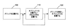
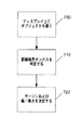
図2は、グリッドキャンバスを生成する例示的な方法を示す上位流れ図である。ステップ100で、行および列の罫線の仮想グリッドを指定することによって、基礎になるグリッドまたは親を作成する。次に、ステップ110で、オブジェクトが有することのできる様々な比率および属性を用いて、1つまたは複数のオブジェクトを定義する。行および列も、この時に定義することができる。定義が完了するまで繰り返される。次に、ステップ120で、グリッドを測定して、オブジェクトを配置する。オブジェクトがグリッド内に配置される前にグリッドが宣言されるが、オブジェクトがグリッド内に配置される前後の任意の時にグリッドを構成できる。例えば、まずページ上でオブジェクトをレイアウトし、その後グリッドを構成することができる。
FIG. 2 is a high-level flow diagram illustrating an exemplary method for generating a grid canvas. In
レイアウトコンテナは、望ましくは、1行1列のグリッドとして開始される。グリッドは、固定数の行および列を有するが、セルを有しない。行および列は、固定または柔軟なものとすることができる。オブジェクトが描かれる時、オブジェクトは、2種類の属性すなわち、罫線の境界ボックスを指定するrow(行)、rowspan(行幅)、col(列)、およびcolspan(列幅)と、left(左)、right(右)、top(上)、bottom(下)、width(幅)、およびheight(高さ)とを有することが好ましい。オブジェクトは、罫線境界ボックス内に配置される。 The layout container is preferably started as a 1-by-1 grid. The grid has a fixed number of rows and columns but no cells. Rows and columns can be fixed or flexible. When an object is drawn, the object has two attributes: row (row), rowspan (row width), col (column), and colspan (column width), which specify the bounding box of the ruled line, and left (left). , Right (right), top (top), bottom (bottom), width (width), and height (height). The object is placed in a ruled line bounding box.
したがって、例示的なグリッドキャンバスによって、豊富なダイアログおよびコンポーネントのレイアウトの作成が可能である。設定される特徴には、行および列単位のレイアウト;重複;絶対値、割合、列および行の「内容に対する(to−content)」および加重比例によるサイズ指定;子の位置に関する完全な制御;およびサイズ指定挙動が含まれることが好ましい。 Thus, the exemplary grid canvas allows creation of rich dialog and component layouts. Features set include: row and column layout; overlap; absolute value, percentage, column and row "to-content" and weighted proportional sizing; full control over child position; and Preferably, a size specification behavior is included.
望ましくは、オブジェクトは、罫線に従って行および列に配置される。行および列は、例えば、ロックすることができ、かつ/または最小サイズを与えることができる。オブジェクトは、オブジェクトが架かる行および列の設定に従って伸びるようにグリッド内に配置することができる。各オブジェクトがセルの異なる領域を使用する複数のオブジェクトは、重複することができる。そのような例を、以下で説明する図5に示す。グリッドはデータ連結可能であり、行および列の数が未知であることが好ましい。 Preferably, the objects are arranged in rows and columns according to ruled lines. Rows and columns can be locked and / or given a minimum size, for example. Objects can be arranged in a grid to extend according to the row and column settings that the object spans. Multiple objects, where each object uses a different area of the cell, can overlap. Such an example is shown in FIG. 5 described below. The grid is preferably data connectable and the number of rows and columns is preferably unknown.
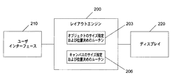
本発明によるシステムには、最適化されたアルゴリズムを実施し、オブジェクトのサイズおよび位置と、グリッド自体の列および行のサイズおよび位置とを処理するレイアウトエンジンが含まれる。図3に示すように、上位概念であって、例示的なレイアウトエンジン200は、コンピュータ内にあるいはマイクロプロセッサまたはコントローラとともに常駐し、ユーザインターフェース210およびディスプレイ220と通信する。レイアウトエンジンには、オブジェクトのサイズ指定および位置決めのルーチン203と、キャンバスのサイズ指定および位置決め用のルーチン206が含まれる。
The system according to the present invention includes a layout engine that implements an optimized algorithm to handle the size and position of objects and the size and position of columns and rows of the grid itself. As shown in FIG. 3, a high-level concept, the
レイアウト判定は、2つのモードで(両方の次元(水平(幅)および垂直(高さ))で独立に)行われることが好ましい。第1の例示的なモードは、(例えば、サイズが、レイアウト作成者によって明示的に設定される場合の)予め定められたサイズに対する計算である。この場合、サイズは、オブジェクトの自然なサイズを考慮に入れて、列(行)の間で分配される。第2の例示的なモードは、(例えば、明示的なサイズが定義されない場合の)自然なサイズに対する計算である。その場合、オブジェクトの自然なサイズおよび列(行)のサイズ指定を考慮に入れ、ならびに割合によるサイズ指定および加重比例によるサイズ指定の場合に列(行)サイズ比率を保存して、グリッドの自然なサイズを決定する。 The layout determination is preferably performed in two modes (independently in both dimensions (horizontal (width) and vertical (height)). The first exemplary mode is a calculation for a predetermined size (eg, when the size is explicitly set by the layout creator). In this case, the size is distributed among the columns (rows) taking into account the natural size of the object. The second exemplary mode is a calculation for natural size (eg, when no explicit size is defined). In that case, the natural size of the object and the column (row) sizing are taken into account, and the column (row) size ratio is preserved in the case of sizing by proportion and sizing by weighted proportion, so Determine the size.
(ランタイム)
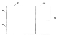
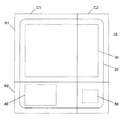
グリッドキャンバスは、ランタイムシステムで使用できる要素である。グリッドキャンバス10は、図4に示されたものなど、行Rおよび列Cに分割される。図4には、2つの行R1、R2と2つの列C1、C2が示されているが、グリッドキャンバスを任意の数の行および列に分割できる。各行および列は、それ自体にサイズ指定情報(例えば、固定、割合、自動、または加重)を有することが望ましい。
(runtime)
The grid canvas is an element that can be used in the runtime system. The
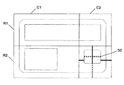
親グリッドキャンバスの任意の位置に子オブジェクトを配置することができる。図5に、4つのオブジェクト20、30、40、および50として例示的な子を示す。オブジェクト20および30は、複数の(1行1列が1セルを形成すると言われる)セルに架かる。オブジェクト20は、行R1およびR2、列C1およびC2にあり、オブジェクト30は、行R1、列C1およびC2に配置されている。オブジェクト40は、行R2および列C1によって形成されるセルに完全に納まり、オブジェクト50は、行R2および列C2によって形成されるセルに完全に納まっている。
Child objects can be placed anywhere on the parent grid canvas. FIG. 5 shows exemplary children as four
ここで、図5のレイアウトの下の行R2が、絶対的な高さを有し、上の行R1が、残りの全てのスペースを消費することが望まれると仮定する。図6に、このレイアウトが、より高いサイズに変更される時の所望の結果を示す。行R2およびそれに含まれるオブジェクトまたはオブジェクトのうちで行R2に含まれる部分が、元の固定された高さのままであることに留意されたい。その一方で、行R1およびそれに含まれるオブジェクトまたはオブジェクトのうちで行R1に含まれる部分は、縦方向にサイズを変更されており、その方向の追加の空間を覆っている。オブジェクトとセルとの相対的な比率は、R1内では、サイズ変更前の元の行R1内と同一のままである。 Now assume that row R2 below the layout of FIG. 5 has an absolute height and that row R1 above is desired to consume all remaining space. FIG. 6 shows the desired result when this layout is changed to a higher size. Note that row R2 and the objects or objects contained therein that are contained in row R2 remain at their original fixed height. On the other hand, the size included in the row R1 and the object included in the row R1 and the portion included in the row R1 are changed in size in the vertical direction and cover the additional space in that direction. The relative ratio between objects and cells remains the same in R1 as in the original row R1 before resizing.
そのようなレイアウトは、行/列を適当に構成して(例えば、下の行の高さ=「150画素」、上の行の高さ=「*」、ここで、「*」は、固定された行/列以外の使用可能なスペースの比率をとることを意味し、他に「*」値を有する行がない場合には、「*」によって残りのスペース全体が使用される)、余白を含むグリッドに対するオブジェクトの関係を構成することによって達成される。C1、R1によって定義されるセルが(0,0)、C2、R1によって定義されるセルが(1,0)、C1、R2によって定義されるセルが(0,1)、およびC2、R2によって定義されるセルが(1,1)である座標系が使用される。オブジェクトの縁とセルの対応する縁の間の距離が、「余白」であると仮定すると、余白は、画素単位でまたは自動と定義され、例えば、オブジェクトの関係を、オブジェクト20、30、40、および50について下記のように定義することができる。
オブジェクト20:グリッド位置=(0,0)−(1,1)(これは、オブジェクトが、図に示すようにセル(0,0)からセル(1,1)に架かることを意味する);余白=(10,10,10,10)(これは、各方向で縁からそれに対応するグリッドセルの縁までの距離が10画素であることを意味する)(図が、原寸通りでないことに留意されたい);幅=自動;高さ=自動。
オブジェクト30:グリッド位置=(0,0)−(1,0);余白=(20,20,20,10);幅=自動;高さ=自動。
オブジェクト40:グリッド位置=(0,1)−(0,1);余白=(20,10,自動,20);幅=固定(例えば100);高さ=自動。
オブジェクト50:グリッド位置=(1,1)−(1,1);余白=(10,10,10,自動);幅=自動;高さ=固定(例えば40)。
Such a layout is configured with appropriate row / column (eg, lower row height = “150 pixels”, upper row height = “*”, where “*” is fixed Means the percentage of available space other than the specified row / column, and if no other row has a “*” value, the entire remaining space is used by “*”) This is accomplished by constructing the object's relationship to a grid containing The cell defined by C1, R1 is (0, 0), the cell defined by C2, R1 is (1,0), the cell defined by C1, R2 is (0, 1), and C2, R2 A coordinate system is used where the defined cell is (1,1). Assuming that the distance between the edge of an object and the corresponding edge of the cell is a “margin”, the margin is defined in pixel units or as automatic, for example, the relationship of the object is defined as
Object 20: Grid position = (0,0) − (1,1) (this means that the object spans cell (0,0) to cell (1,1) as shown); Margin = (10, 10, 10, 10) (this means that the distance from the edge to the edge of the corresponding grid cell in each direction is 10 pixels) (note that the figure is not to scale) Width = automatic; height = automatic.
Object 30: Grid position = (0,0) − (1,0); margin = (20, 20, 20, 10); width = automatic; height = automatic.
Object 40: Grid position = (0, 1) − (0, 1); margin = (20, 10, automatic, 20); width = fixed (for example, 100); height = auto.
Object 50: Grid position = (1,1) − (1,1); margin = (10, 10, 10, automatic); width = automatic; height = fixed (for example, 40).
望ましくは、明示的な値が、明示的な測定値を表し、自動値が、残りの使用可能なスペースを消費する。様々な実施形態で、余白を全ての辺について指定でき、追加のアタッチメントフラグを追加できる。さらに、子が親の達成できない値を要求する場合があり、この場合、グリッドキャンバスは、例えばエラーメッセージを返すか、または有効になるように値を修正することによって、既定の範囲内に納めることができる。 Preferably, the explicit value represents an explicit measurement value and the automatic value consumes the remaining available space. In various embodiments, margins can be specified for all sides and additional attachment flags can be added. In addition, the child may request a value that the parent cannot achieve, in which case the grid canvas will fit within a predefined range, for example by returning an error message or modifying the value to be valid. Can do.
ランタイムは、子オブジェクトを測定し、子オブジェクトが動作する任意の制約に従って行の幅および列の高さを割り当てた後、使用可能な空間の量に基づいて子オブジェクトの位置決めを行うように機能する。 The runtime functions to measure the child object, assign a row width and column height according to any constraints that the child object operates on, and then position the child object based on the amount of space available .
(デザインタイム)
デザインタイムプロセスは、最小限の量のユーザ指定を使用してグリッドキャンバスレイアウトを自動的に作成する動作である。レイアウト作成者またはレイアウト設計者は、レイアウト形状およびレイアウトの動的挙動を定義することができるようになる。
(Design time)
The design time process is an operation that automatically creates a grid canvas layout using a minimal amount of user designation. The layout creator or layout designer will be able to define the layout shape and the dynamic behavior of the layout.
図7に、本発明によるグリッドキャンバスレイアウトを作成する例示的な方法を示す。ステップ700で、設計者がディスプレイの特定の位置(例えば、ディスプレイ上のユーザインターフェース内)にオブジェクトを置く。ステップ710で、その罫線境界ボックスを判定する。これは、上述のグリッド位置プロパティにマッピングされる。その後、ステップ720で、この罫線境界ボックスの範囲を所望の位置と比較することにより、例えばデフォルト方式に従って適当な余白および幅/高さを決めることができる。例示的なデフォルト方式は、(1)指定された位置が罫線ボックス範囲の左半分に完全におさまる場合には、明示的な左余白および幅を設定し、右余白に自動を設定し、(2)指定された位置が、罫線ボックス範囲の右半分に完全に納まる場合には、明示的な右余白および幅を設定し、左余白に自動を設定し、(3)指定された位置が罫線ボックス範囲の中央線に架かる場合には、明示的な左右の余白を設定し、幅に自動を設定し、(4)高さおよび上下余白を類似する方法で処理するというものである。
FIG. 7 illustrates an exemplary method for creating a grid canvas layout according to the present invention. At
図8に、特にオブジェクト50の行R2列C2に関して、上記の設定を説明するのに都合のよい例示的なグリッドキャンバスを示す。固定値を、実線として示し、自動値を、破線として示す。図に示す6つの位置決めインジケータ(高さ、幅、および余白)のいずれかを切り替えることにより、ユーザは位置決め方式を変更することができ、自動値のいずれかを現在有効な固定値に置き換えることができる。ユーザは必要に応じて、4つの外部アンカを所望の他の罫線に移動することにより罫線境界ボックスを調整することもできる。オブジェクトが移動され、またはサイズを変更される際、ユーザが明示した要望を除き、その新しい位置は再評価され、新たな値が計算される。行または列が追加され、または除去されるとき、ユーザが明示した要望を除き、近くのオブジェクトが再計算される。
FIG. 8 shows an exemplary grid canvas that is useful for explaining the above settings, particularly with respect to row R2 and column C2 of
例示的な設計方法に、オブジェクトの罫線境界ボックスを判定するステップが含まれる。上辺が中線の上にある場合、上の余白が固定される。下辺も中線の上にある場合、その高さが固定され、下辺は動的になるように設定される。しかし、下辺が中線の下にある場合、下辺が固定され、高さが、動的になるように設定される。割り当ては、新しい罫線が描かれる時に自動的に更新される。 An exemplary design method includes determining an object's ruled bounding box. If the top is above the middle line, the top margin is fixed. If the bottom is also above the midline, its height is fixed and the bottom is set to be dynamic. However, if the lower side is below the middle line, the lower side is fixed and the height is set to be dynamic. The assignment is automatically updated when a new rule is drawn.
例として、シーンに描くことができる罫線があり、オブジェクトを普通に描き、修正することができると仮定する(例えば、オブジェクトに、意のままに罫線を架けることができる)。そのような環境では、図9(オブジェクトの例示的な色として「red(赤)」が提供される)に示された複数の重複する水平オブジェクト770および垂直オブジェクト780の絵に関して、下記の例示的な解決が提供される。
As an example, suppose there is a ruled line that can be drawn in the scene, and the object can be drawn and modified normally (eg, the object can be ruled at will). In such an environment, for the multiple overlapping horizontal and

列および行の情報が最初にあり、子の順序が、描画順序であることに留意されたい。さらに、各オブジェクトは、そのオブジェクトがその中に納まるグリッド長方形を記述する付加プロパティ(attached properties)を有する。余白は、指定されたグリッド長方形に対して値を決められる。サイズ変更中の挙動を制御する追加snapto情報を付け足すことができる。この罫線値にアクセスできるシステムは、グリッド境界ボックス、望ましくはグリッド境界およびオフセットとの関係から長方形と解釈する。 Note that the column and row information is first, and the order of the children is the drawing order. In addition, each object has an attached property that describes the grid rectangle in which the object fits. The margin can be determined for the specified grid rectangle. Additional snapto information that controls the behavior during resizing can be added. A system that has access to this ruled line value interprets it as a rectangle due to its relation to the grid bounding box, preferably the grid bounds and offset.
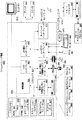
(例示的なコンピューティング環境)
図10に、本発明を実施できる適切なコンピューティングシステム環境800の例を示す。コンピューティングシステム環境800は、適切なコンピューティング環境の一例にすぎず、本発明の使用または機能性の範囲に関する制限を示唆することを意図されたものではない。コンピューティング環境800は、例示的なオペレーティング環境800に示された任意の構成要素、またはその組合せに関する依存性もしくは要件を有するものと解釈されるべきでない。
(Example computing environment)
FIG. 10 illustrates an example of a suitable
本発明は、多数の他の汎用または専用のコンピューティングシステム環境またはコンピューティングシステム構成と協働する。本発明の用途に適する周知のコンピューティングシステム、コンピューティング環境、および/またはコンピューティング構成の例に、パーソナルコンピュータ、サーバコンピュータ、ハンドヘルド装置、ラップトップ装置、マルチプロセッサシステム、マイクロプロセッサに基づくシステム、セットトップボックス、プログム可能な民生用電子機器、ネットワークPC、ミニコンピュータ、メインフレームコンピュータ、上記のシステムまたは装置のいずれかを含む分散コンピューティング環境などが含まれるが、これに限定されない。 The invention works with numerous other general purpose or special purpose computing system environments or configurations. Examples of well-known computing systems, computing environments, and / or computing configurations suitable for use with the present invention include personal computers, server computers, handheld devices, laptop devices, multiprocessor systems, microprocessor-based systems, sets This includes, but is not limited to, top boxes, programmable consumer electronics, network PCs, minicomputers, mainframe computers, distributed computing environments including any of the above systems or devices, and the like.
本発明を、プログラムモジュールなど、コンピュータによって実行されるコンピュータ実行可能な命令の一般的な文脈で説明することができる。一般にプログラムモジュールには、特定のタスクを実行し、または特定の抽象データ型を実施する、ルーチン、プログラム、オブジェクト、コンポーネント、データ構造などが含まれる。本発明は、通信ネットワークまたは他のデータ伝送媒体を介して接続されたリモート処理装置によってタスクが実行される、分散コンピューティング環境で実行することもできる。分散コンピューティング環境では、プログラムモジュールおよび他のデータを、メモリ記憶装置を含むリモートおよびローカルの両方のコンピュータ記憶媒体に配置することができる。 The invention can be described in the general context of computer-executable instructions, such as program modules, being executed by a computer. Generally, program modules include routines, programs, objects, components, data structures, etc. that perform particular tasks or implement particular abstract data types. The invention may also be practiced in distributed computing environments where tasks are performed by remote processing devices that are linked through a communications network or other data transmission medium. In a distributed computing environment, program modules and other data can be located in both remote and local computer storage media including memory storage devices.
図10を参照すると、本発明を実施する例示的なシステムに、コンピュータ810型の汎用コンピューティング装置が含まれる。コンピュータ810のコンポーネントに、処理装置820、システムメモリ830、およびシステムメモリを含む様々なシステムコンポーネントを処理装置820に結合するシステムバス821が含まれる。システムバス821は、メモリバス、メモリコントローラ、周辺バス、および任意の様々なバスアーキテクチャを使用するローカルバスを含む任意の数種のバス構造とすることができる。限定ではなく例として、そのようなアーキテクチャには、ISA(Industry Standard Architecture)バス、MCA(Micro Channel Architecture)バス、EISA(Enhanced ISA)バス、VESA(Video Electronics Standards Association)ローカルバス、および(メザニンバスとも称する)PCI(Peripheral Component Interconnect)バスが含まれる。
With reference to FIG. 10, an exemplary system for implementing the invention includes a general-purpose computing device of the
コンピュータ810に、通常は、様々なコンピュータ読取り可能な媒体が含まれる。コンピュータ読取り可能な媒体は、コンピュータ810によってアクセスでき、揮発性および不揮発性、取外し可能なおよび固定の両方を含む任意使用可能な媒体とすることができる。限定ではなく例として、コンピュータ読取り可能な媒体に、コンピュータ記憶媒体および通信媒体を含めることができる。コンピュータ記憶媒体に、コンピュータ読取り可能な命令、データ構造、プログラムモジュール、または他のデータなどの情報を保管する任意の方法または技術で実施された、揮発性および不揮発性、取外し可能なおよび固定の両方の媒体が含まれる。コンピュータ記憶媒体には、RAM、ROM、EEPROM、フラッシュメモリ、または他のメモリテクノロジ、CD−ROM、ディジタル多用途ディスク(DVD)、または他の光学ディスクストレージ、磁気カセット、磁気テープ、磁気ディスクストレージ、または他の磁気記憶装置、あるいは所望の情報の保管に使用でき、コンピュータ810によってアクセスすることができる他の全ての媒体が含まれるが、これに限定されない。通信媒体によって、通常は、搬送波または他の転送機構などの変調されたデータ信号内のコンピュータ読取り可能な命令、データ構造、プログラムモジュール、または他のデータが実施され、通信媒体には、全ての情報配信媒体が含まれる。用語「変調されたデータ信号」は、信号において情報を符号化する方法によってその特性の1つまたは複数を設定または変更された信号を意味する。限定ではなく例として、通信媒体には、有線ネットワークまたは直接配線接続などの有線媒体と、音響、RF、赤外線、および他の無線媒体などの無線媒体が含まれる。上記の任意の組合せも、コンピュータ読取り可能な媒体の範囲に含まれるべきである。
システムメモリ830には、ROM 831およびRAM 832などの揮発性メモリおよび/または不揮発性メモリ型のコンピュータ記憶媒体が含まれる。起動中などにコンピュータ810内の要素間での情報の転送を助ける基本ルーチンを含む基本入出力システム833(BIOS)が、通常はROM 831に保管される。RAM 832には、通常は、処理装置820から即座にアクセス可能な、かつ/または処理装置820によって現在操作中のデータおよび/またはプログラムモジュールが含まれる。限定ではなく例として、図10に、オペレーティングシステム834、アプリケーションプログラム835、他のプログラムモジュール836、およびプログラムデータ837を示す。
The
コンピュータ810に、他の取外し可能な/固定の、揮発性/不揮発性のコンピュータ記憶媒体も含めることができる。単に一例として、図10に、固定の不揮発性磁気媒体から読み取り、または書き込むハードディスクドライブ841、取外し可能な不揮発性磁気ディスク852から読み取り、または書き込む磁気ディスクドライブ851、CD−ROMまたは他の光媒体などの取外し可能な不揮発性光ディスク856から読み取り、または書き込む光ディスクドライブ855を示す。例示的なオペレーティング環境で使用できる他の取外し可能な/固定の、揮発性/不揮発性のコンピュータ記憶媒体に、磁気テープカセット、フラッシュメモリカード、ディジタル多用途ディスク、ディジタルビデオテープ、ソリッドステートRAM、ソリッドステートROMなどが含まれるが、これに限定されない。ハードディスクドライブ841は、通常、インターフェース840などの固定のメモリインターフェースを介してシステムバス821に接続され、磁気ディスクドライブ851および光ディスクドライブ855は、通常、インターフェース850などの取外し可能なメモリインターフェースによってシステムバス821に接続される。
The
ドライブおよびそれに関連するコンピュータ記憶媒体は、コンピュータ810のコンピュータ読取り可能な命令、データ構造、プログラムモジュール、および他のデータのストレージを提供する。図10に、一例として、ハードディスクドライブ841を、オペレーティングシステム844、アプリケーションプログラム845、他のプログラムモジュール846、およびプログラムデータ847を保管するものとして示す。これらのコンポーネントを、オペレーティングシステム834、アプリケーションプログラム835、他のプログラムモジュール836、およびプログラムデータ837と同一のまたは異なるもののいずれかとすることができることに留意されたい。オペレーティングシステム844、アプリケーションプログラム845、他のプログラムモジュール846、およびプログラムデータ847は、最低限でも異なるコピーであることを示すために、異なる符号を与えられている。ユーザは、キーボード862および、一般にマウス、トラックボール、またはタッチパッドと称するポインティングデバイス861などの入力装置を介してコンピュータ810にコマンドおよび情報を入力することができる。他の入力装置(図示せず)に、マイクロホン、ジョイスティック、ゲームパッド、衛星パラボラアンテナ、スキャナなどを含めることができる。上記および他の入力装置は、しばしば、システムバスに結合されたユーザ入力インターフェース860を介して処理装置820に接続されるが、パラレルポート、ゲームポート、またはUSB(universal serial bus)などの他のインターフェースおよびバス構造によって接続することができる。モニタ891または他のタイプのディスプレイ装置も、ビデオインターフェース890などのインターフェースを介してシステムバス821に接続される。モニタのほかに、コンピュータに、スピーカ897およびプリンタ896など、出力周辺インターフェース895を介して接続できる他の周辺出力装置も含めることができる。
The drive and associated computer storage media provide storage of computer
コンピュータ810は、リモートコンピュータ880などの1つまたは複数のリモートコンピュータへの論理接続を用いて、ネットワーク化された環境で動作することができる。リモートコンピュータ880は、パーソナルコンピュータ、サーバ、ルータ、ネットワークPC、ピア装置、または他の一般的なネットワークノードとすることができる。リモートコンピュータ880は、通常、上述のコンピュータ810に関する要素の多くまたは全てを含むが、図10には、メモリ記憶装置881のみを示した。図に示す論理接続には、LAN 871およびWAN 873が含まれるが、他のネットワークも含めることができる。そのようなネットワーキング環境は、オフィス、企業規模のコンピュータネットワーク、イントラネット、およびインターネットで一般的である。
LANネットワーキング環境で使用される場合、コンピュータ810は、ネットワークインターフェースまたはネットワークアダプタ870を介してLAN 871に接続される。WANネットワーキング環境で使用される場合、コンピュータ810は、通常は、インターネットなどのWAN 873を介して通信を確立するモデム872または他の手段を含む。モデム872は、内蔵または外付けとすることができるが、ユーザ入力インターフェース860または他の適当な機構を介してシステムバス821に接続することができる。ネットワーク化された環境では、コンピュータ810に関する図示されたプログラムモジュールまたはその一部を、リモートメモリ記憶装置に保管することができる。限定ではなく例として、図10に、メモリ装置881に常駐するリモートアプリケーションプログラム885を示す。図示のネットワーク接続が例示的であり、コンピュータの間の通信リンクを確立する他の手段を使用できることを理解されたい。
When used in a LAN networking environment, the
上述のように、本発明の例示的な実施形態を、様々なコンピューティング装置について説明したが、基礎になる概念は、全てのコンピューティング装置またはコンピューティングシステムに適用することができる。 As described above, the exemplary embodiments of the present invention have been described for various computing devices, but the underlying concepts can be applied to any computing device or computing system.
本明細書に記載の様々な技法は、ハードウェアまたはソフトウェアに関して、あるいは、適当な場合にこの両方の組合せに関して実施することができる。したがって、本発明の方法および装置、あるいはその態様または部分は、フロッピ(登録商標)ディスク、CD−ROM、ハードドライブ、または他の機械読取り可能な記憶媒体などの有形の媒体で実施されるプログラムコード(すなわち命令)の形をとることができ、このプログラムコードが、コンピュータなどの機械に読み込まれ、これによって実行される時に、その機械が、本発明を実行する装置になる。プログム可能なコンピュータで実行されるプログラムコードの場合に、コンピューティング装置には、一般に、プロセッサ、プロセッサによって読取り可能な記憶媒体(揮発性および不揮発性のメモリおよび/または記憶要素を含む)、少なくとも1つの入力装置、および少なくとも1つの出力装置が含まれる。プログラムを、必要に応じて、アセンブリ言語または機械語で実施することができる。どの場合でも、言語は、コンパイル済みまたは解釈済み言語とすることができ、ハードウェア実施形態と組み合わせることができる。 The various techniques described herein may be implemented with respect to hardware or software, or a combination of both where appropriate. Accordingly, the method and apparatus of the present invention, or aspects or portions thereof, may be implemented by program code implemented on a tangible medium such as a floppy disk, CD-ROM, hard drive, or other machine-readable storage medium. (Ie, instructions), and when the program code is read into and executed by a machine such as a computer, the machine becomes a device for carrying out the invention. In the case of program code executing on a programmable computer, the computing device generally includes a processor, a processor-readable storage medium (including volatile and non-volatile memory and / or storage elements), at least one One input device and at least one output device are included. The program can be implemented in assembly language or machine language as required. In any case, the language can be a compiled or interpreted language and can be combined with a hardware implementation.
本発明の方法および装置は、電気配線またはケーブリング、光ファイバ、または他の形の伝送を介するなど、何らかの伝送媒体を介して伝送されるプログラムコードの形で実施される通信を介して実行することもでき、このプログラムコードが、EPROM、ゲートアレイ、プログム可能な論理装置(PLD)、クライアントコンピュータなどの機械によって受信され、読み込まれ、実行される場合、その機械は本発明を実行する装置になる。汎用プロセッサで実施される場合、プログラムコードがプロセッサと組み合わされ、本発明の機能性を呼び出すように動作する独自の装置を提供する。さらに、本発明に関して使用されるストレージ技法を、常にハードウェアとソフトウェアの組合せとすることができる。 The methods and apparatus of the present invention perform via communications implemented in the form of program code transmitted over some transmission medium, such as via electrical wiring or cabling, optical fiber, or other forms of transmission. If the program code is received, read and executed by a machine such as an EPROM, a gate array, a programmable logic device (PLD), a client computer, etc., the machine is a device that implements the present invention. Become. When implemented on a general-purpose processor, the program code combines with the processor to provide a unique apparatus that operates to invoke the functionality of the present invention. Further, the storage technique used in connection with the present invention can always be a combination of hardware and software.
本発明を、様々な図面の好ましい実施形態に関して説明したが、他の類似する実施形態を用いることができ、あるいは、本発明から逸脱せずに、本発明の同一の機能を実行するために記載の実施形態に対する修正および追加を行えることを理解されたい。したがって、本発明は、単一の実施形態に限定されるのではなく、特許請求の範囲による範囲で解釈されなければならない。 Although the present invention has been described with reference to preferred embodiments in the various drawings, other similar embodiments can be used or described to perform the same functions of the present invention without departing from the invention. It should be understood that modifications and additions to the embodiments can be made. Accordingly, the invention is not limited to a single embodiment, but should be construed in the scope of the claims.
10 グリッドキャンバス
20〜50 オブジェクト
R1、R2 行
C1、C2 列
770 水平オブジェクト
780 垂直オブジェクト
841 ハードディスクドライブ
851 磁気ディスクドライブ
852 取外し可能な不揮発性磁気ディスク
855 光ディスクドライブ
856 取外し可能な不揮発性光ディスク
881 メモリ記憶装置
10 Grid Canvas 20-50 Object R1, R2 Row C1,
Claims (28)
前記グリッド上にオブジェクトを定義するステップと、
前記グリッド上に複数の行および列を定義するステップと、
前記グリッド上に前記オブジェクトを配置するステップと
を備えたことを特徴とするグリッドキャンバスを生成する方法。 Defining the grid, and
Defining an object on the grid;
Defining a plurality of rows and columns on the grid;
Placing the object on the grid; and generating a grid canvas.
前記オブジェクトに対して罫線境界ボックスを決定するステップと、
前記オブジェクトに対して複数の属性を実行するステップと
を備えたことを特徴とするグリッドキャンバスレイアウトを作成する方法。 Placing an object on the display;
Determining a ruled bounding box for the object;
A method for creating a grid canvas layout comprising: executing a plurality of attributes on the object.
グリッドを定義するステップと、
前記グリッドに関するオブジェクト定義信号を受け取るステップと、
前記グリッド上に複数の行および列を定義するステップと、
前記グリッド上に前記オブジェクトを表示するステップと
を備えたことを特徴とするグリッドキャンバスを生成する方法。 In a computer system having a graphical user interface and a display,
Defining the grid, and
Receiving an object definition signal for the grid;
Defining a plurality of rows and columns on the grid;
Displaying the object on the grid; and generating a grid canvas.
Displaying a second object on the grid, the grid including a plurality of virtual cells, the object and the second object being at least one of the same cells of the plurality of virtual cells; 24. The method according to claim 23, wherein:
Applications Claiming Priority (1)
| Application Number | Priority Date | Filing Date | Title |
|---|---|---|---|
| US10/815,067 US20050237321A1 (en) | 2004-03-31 | 2004-03-31 | Grid canvas |
Publications (2)
| Publication Number | Publication Date |
|---|---|
| JP2005293552A true JP2005293552A (en) | 2005-10-20 |
| JP2005293552A5 JP2005293552A5 (en) | 2008-03-27 |
Family
ID=34887735
Family Applications (1)
| Application Number | Title | Priority Date | Filing Date |
|---|---|---|---|
| JP2005033505A Pending JP2005293552A (en) | 2004-03-31 | 2005-02-09 | Grid canvas |
Country Status (18)
| Country | Link |
|---|---|
| US (1) | US20050237321A1 (en) |
| EP (1) | EP1583036A3 (en) |
| JP (1) | JP2005293552A (en) |
| KR (1) | KR101130487B1 (en) |
| CN (1) | CN1677343B (en) |
| AU (1) | AU2005200389B2 (en) |
| BR (1) | BRPI0500582A (en) |
| CA (1) | CA2496101A1 (en) |
| CO (1) | CO5680120A1 (en) |
| IL (1) | IL167162A (en) |
| MX (1) | MXPA05002325A (en) |
| MY (1) | MY144679A (en) |
| NO (1) | NO20051057L (en) |
| NZ (1) | NZ538523A (en) |
| RU (1) | RU2376639C2 (en) |
| SG (1) | SG115729A1 (en) |
| TW (1) | TW200532485A (en) |
| ZA (1) | ZA200501720B (en) |
Cited By (4)
| Publication number | Priority date | Publication date | Assignee | Title |
|---|---|---|---|---|
| JP2008035475A (en) * | 2006-07-04 | 2008-02-14 | Seiko Epson Corp | Document editing support device, program, and storage medium |
| JP2012099098A (en) * | 2010-10-25 | 2012-05-24 | Konica Minolta Laboratory Usa Inc | Method of determining height of cell of table, computer-readable medium, and system |
| JP2012198670A (en) * | 2011-03-18 | 2012-10-18 | Fujitsu Ltd | Figure drawing program and figure drawing device |
| JP2019512787A (en) * | 2016-03-08 | 2019-05-16 | ネイバー ビジネス プラットフォーム コーポレーション | Input recognition method and system using variable grid index |
Families Citing this family (61)
| Publication number | Priority date | Publication date | Assignee | Title |
|---|---|---|---|---|
| JP2006099385A (en) * | 2004-09-29 | 2006-04-13 | Fujitsu Ltd | Shape design support program |
| US7581169B2 (en) * | 2005-01-14 | 2009-08-25 | Nicholas James Thomson | Method and apparatus for form automatic layout |
| US20080062204A1 (en) * | 2006-09-08 | 2008-03-13 | Microsoft Corporation | Automated pixel snapping for anti-aliased rendering |
| US7979785B1 (en) | 2006-10-04 | 2011-07-12 | Google Inc. | Recognizing table of contents in an image sequence |
| US8782551B1 (en) * | 2006-10-04 | 2014-07-15 | Google Inc. | Adjusting margins in book page images |
| US7912829B1 (en) | 2006-10-04 | 2011-03-22 | Google Inc. | Content reference page |
| US20080115081A1 (en) * | 2006-11-09 | 2008-05-15 | Microsoft Corporation | Enhanced windows management feature |
| JP4337867B2 (en) * | 2006-12-01 | 2009-09-30 | セイコーエプソン株式会社 | Document editing support device, document editing device, program, and storage medium |
| US20080218532A1 (en) * | 2007-03-08 | 2008-09-11 | Microsoft Corporation | Canvas-like authoring experience atop a layout engine |
| US7712226B1 (en) * | 2007-09-21 | 2010-05-11 | Stearns David R | Grid system apparatus |
| US20090106648A1 (en) * | 2007-10-19 | 2009-04-23 | Microsoft Corporation | Positioning content using a grid |
| KR100917756B1 (en) * | 2007-12-18 | 2009-09-15 | 한국전자통신연구원 | Method and apparatus for forming lattice map for robot by use of drawings |
| US9400597B2 (en) * | 2008-07-23 | 2016-07-26 | Microsoft Technology Licensing, Llc | Presenting dynamic grids |
| US8751921B2 (en) * | 2008-07-24 | 2014-06-10 | Microsoft Corporation | Presenting annotations in hierarchical manner |
| US20100218090A1 (en) * | 2009-02-26 | 2010-08-26 | Universal - Ad Ltd. | Sub-page-based page layout system and method thereof |
| US8612858B2 (en) * | 2009-05-01 | 2013-12-17 | Apple Inc. | Condensing graphical representations of media clips in a composite display area of a media-editing application |
| US20110249007A1 (en) * | 2010-04-13 | 2011-10-13 | Disney Enterprises, Inc. | Computer rendering of drawing-tool strokes |
| US8819557B2 (en) | 2010-07-15 | 2014-08-26 | Apple Inc. | Media-editing application with a free-form space for organizing or compositing media clips |
| US20120030550A1 (en) * | 2010-07-28 | 2012-02-02 | Chin Ai | Method for editing multimedia |
| US8760453B2 (en) * | 2010-09-01 | 2014-06-24 | Microsoft Corporation | Adaptive grid generation for improved caching and image classification |
| US9679404B2 (en) | 2010-12-23 | 2017-06-13 | Microsoft Technology Licensing, Llc | Techniques for dynamic layout of presentation tiles on a grid |
| US9436685B2 (en) | 2010-12-23 | 2016-09-06 | Microsoft Technology Licensing, Llc | Techniques for electronic aggregation of information |
| US8751924B2 (en) | 2011-04-27 | 2014-06-10 | Microsoft Corporation | Rule-based grid independent of content |
| US9013510B2 (en) * | 2011-07-29 | 2015-04-21 | Google Inc. | Systems and methods for rendering user interface elements in accordance with a device type |
| EP2555165B1 (en) * | 2011-08-04 | 2020-04-15 | Samsung Electronics Co., Ltd. | Method and device for packing multiple images |
| US9164777B2 (en) * | 2011-08-30 | 2015-10-20 | Microsoft Technology Licensing, Llc | Determining the display of equal spacing guides between diagram shapes |
| TWI579827B (en) * | 2011-09-23 | 2017-04-21 | 微軟技術授權有限責任公司 | Techniques for dynamic layout of presentation tiles on a grid |
| US8493411B2 (en) * | 2011-09-30 | 2013-07-23 | Google, Inc. | Methods and apparatus for extensions to directed graphs with minimal and maximal constraints are encoded by arcs in opposite directions |
| US8866854B2 (en) | 2011-10-31 | 2014-10-21 | Microsoft Corporation | Consolidated orthogonal guide creation |
| US20130167072A1 (en) * | 2011-12-22 | 2013-06-27 | Sap Portals Israel Ltd. | Smart and Flexible Layout Context Manager |
| US8458587B1 (en) * | 2012-01-27 | 2013-06-04 | Think-Cell Software Gmbh | Method of entering page layout constraints into a computer |
| US9323436B2 (en) | 2012-04-05 | 2016-04-26 | Microsoft Technology Licensing, Llc | Utilizing drawing guides in determining the display of smart guides in a drawing program |
| USD727929S1 (en) * | 2012-05-02 | 2015-04-28 | Pantech Co., Ltd. | Display screen or portion thereof with graphical user interface |
| USD727337S1 (en) * | 2012-05-02 | 2015-04-21 | Pantech Co., Ltd. | Display screen or portion thereof with graphical user interface |
| USD728592S1 (en) * | 2012-05-02 | 2015-05-05 | Pantech Co., Ltd. | Display screen or portion thereof with graphical user interface |
| USD728590S1 (en) * | 2012-05-02 | 2015-05-05 | Pantech Co., Ltd. | Display screen or portion thereof with graphical user interface |
| USD728591S1 (en) * | 2012-05-02 | 2015-05-05 | Pantech Co., Ltd. | Display screen or portion thereof with graphical user interface |
| USD727931S1 (en) * | 2012-05-02 | 2015-04-28 | Pantech Co., Ltd. | Display screen or portion thereof with graphical user interface |
| USD727338S1 (en) * | 2012-05-02 | 2015-04-21 | Pantech Co., Ltd. | Display screen or portion thereof with graphical user interface |
| US9548042B2 (en) * | 2012-06-28 | 2017-01-17 | Adobe Systems Incorporated | Responsive document breakpoints systems and methods |
| KR101221948B1 (en) * | 2012-07-19 | 2013-02-08 | (주)지란지교소프트 | Method for displaying windows and recording-medium recorded program thereof |
| US20140095986A1 (en) * | 2012-09-30 | 2014-04-03 | Vinay Krishnaswamy | Baseline Alignment |
| CN103870508B (en) * | 2012-12-18 | 2016-04-20 | 腾讯科技(深圳)有限公司 | A kind of webpage Zoom method, device and system |
| US9280523B2 (en) * | 2013-01-23 | 2016-03-08 | Go Daddy Operating Company, LLC | System for conversion of website content |
| US10719829B2 (en) | 2013-09-09 | 2020-07-21 | Touchtunes Music Corporation | Techniques for processing pin-inclusive transactions in connection with an electronic device |
| US9921717B2 (en) | 2013-11-07 | 2018-03-20 | Touchtunes Music Corporation | Techniques for generating electronic menu graphical user interface layouts for use in connection with electronic devices |
| US9582825B2 (en) | 2014-03-24 | 2017-02-28 | Touchtunes Music Corporation | Systems, apparatuses, and methods for ordering items from an electronic menu, and servicing thereof |
| US10037122B2 (en) | 2014-09-26 | 2018-07-31 | Oracle International Corporation | Canvas layout algorithm |
| JP6465277B6 (en) * | 2014-10-23 | 2019-03-13 | Dynabook株式会社 | Electronic device, processing method and program |
| US10037131B2 (en) | 2015-05-21 | 2018-07-31 | Adobe Systems Incorporated | Facilitating object set replication |
| US10325384B2 (en) | 2015-08-20 | 2019-06-18 | International Business Machines Corporation | Multi-attribute relation network visualization and interaction interface |
| US9959257B2 (en) | 2016-01-08 | 2018-05-01 | Adobe Systems Incorporated | Populating visual designs with web content |
| CN115048088A (en) * | 2016-05-17 | 2022-09-13 | 谷歌有限责任公司 | System and method for automatically determining layout constraints |
| KR101866033B1 (en) * | 2016-07-05 | 2018-06-08 | 에스케이 주식회사 | Method for Rendering a Grid in a Web Browser and Computing System applying the same |
| CN108564637B (en) * | 2018-04-19 | 2022-03-29 | 北京知道创宇信息技术股份有限公司 | Geometric model arrangement method and device |
| US10824318B1 (en) | 2018-10-24 | 2020-11-03 | Amdocs Development Limited | System, method, and computer program for automatic user interface layout organization |
| US10984170B2 (en) * | 2018-12-26 | 2021-04-20 | Software Ag | Systems and/or methods for dynamic layout design |
| CN110162367B (en) * | 2019-05-10 | 2020-11-24 | 上海莉莉丝科技股份有限公司 | Method, system, device and medium for user interface adaptive configuration |
| CN110211131A (en) * | 2019-05-21 | 2019-09-06 | 上海阿几网络技术有限公司 | A kind of automatic expanding method of planar design size based on Parametric designing |
| CN111651161B (en) * | 2020-07-16 | 2023-04-18 | 深圳市易鸿达软件开发有限公司 | Graphical interface construction method and device, computer equipment and storage medium |
| CN112346725B (en) * | 2020-11-05 | 2023-12-12 | 南方电网数字电网研究院有限公司 | Page design method, device, equipment and storage medium |
Citations (2)
| Publication number | Priority date | Publication date | Assignee | Title |
|---|---|---|---|---|
| JPH11102446A (en) * | 1997-09-29 | 1999-04-13 | Fujitsu Ltd | Graphics input device |
| JP2002251624A (en) * | 2001-02-23 | 2002-09-06 | Toppan Printing Co Ltd | System, method, and program for arranging object, and recording medium for recording program for arranging object |
Family Cites Families (8)
| Publication number | Priority date | Publication date | Assignee | Title |
|---|---|---|---|---|
| US5490241A (en) * | 1989-10-06 | 1996-02-06 | Xerox Corporation | Interactive computer graphics system for making precise drawings |
| US5796401A (en) * | 1996-08-09 | 1998-08-18 | Winer; Peter W. | System for designing dynamic layouts adaptable to various display screen sizes and resolutions |
| US6323879B1 (en) * | 1998-05-14 | 2001-11-27 | Autodesk, Inc. | Method and system for determining the spacing of objects |
| US6392673B1 (en) * | 1998-09-04 | 2002-05-21 | Microsoft Corporation | Method for resizing user interface elements for an operating system |
| US6694487B1 (en) * | 1998-12-10 | 2004-02-17 | Canon Kabushiki Kaisha | Multi-column page preview using a resizing grid |
| US6377285B1 (en) * | 1999-01-29 | 2002-04-23 | Sony Corporation | Zooming space-grid for graphical user interface |
| US6919890B2 (en) * | 2000-09-28 | 2005-07-19 | Curl Corporation | Grid and table layout using elastics |
| US7136081B2 (en) * | 2001-05-25 | 2006-11-14 | Nvidia Corporation | System and method of line sampling object scene information |
-
2004
- 2004-03-31 US US10/815,067 patent/US20050237321A1/en not_active Abandoned
-
2005
- 2005-01-31 AU AU2005200389A patent/AU2005200389B2/en not_active Ceased
- 2005-02-03 CA CA002496101A patent/CA2496101A1/en not_active Abandoned
- 2005-02-09 JP JP2005033505A patent/JP2005293552A/en active Pending
- 2005-02-15 SG SG200500887A patent/SG115729A1/en unknown
- 2005-02-17 TW TW094104695A patent/TW200532485A/en unknown
- 2005-02-18 BR BR0500582-5A patent/BRPI0500582A/en not_active IP Right Cessation
- 2005-02-22 KR KR1020050014608A patent/KR101130487B1/en not_active IP Right Cessation
- 2005-02-25 NO NO20051057A patent/NO20051057L/en not_active Application Discontinuation
- 2005-02-28 ZA ZA200501720A patent/ZA200501720B/en unknown
- 2005-02-28 RU RU2005105514/02A patent/RU2376639C2/en not_active IP Right Cessation
- 2005-02-28 NZ NZ538523A patent/NZ538523A/en not_active IP Right Cessation
- 2005-02-28 MX MXPA05002325A patent/MXPA05002325A/en unknown
- 2005-02-28 CN CN2005100531143A patent/CN1677343B/en not_active Expired - Fee Related
- 2005-02-28 MY MYPI20050809A patent/MY144679A/en unknown
- 2005-03-01 IL IL167162A patent/IL167162A/en not_active IP Right Cessation
- 2005-03-15 CO CO05024082A patent/CO5680120A1/en not_active Application Discontinuation
- 2005-03-18 EP EP05102145A patent/EP1583036A3/en not_active Withdrawn
Patent Citations (2)
| Publication number | Priority date | Publication date | Assignee | Title |
|---|---|---|---|---|
| JPH11102446A (en) * | 1997-09-29 | 1999-04-13 | Fujitsu Ltd | Graphics input device |
| JP2002251624A (en) * | 2001-02-23 | 2002-09-06 | Toppan Printing Co Ltd | System, method, and program for arranging object, and recording medium for recording program for arranging object |
Cited By (5)
| Publication number | Priority date | Publication date | Assignee | Title |
|---|---|---|---|---|
| JP2008035475A (en) * | 2006-07-04 | 2008-02-14 | Seiko Epson Corp | Document editing support device, program, and storage medium |
| JP4665933B2 (en) * | 2006-07-04 | 2011-04-06 | セイコーエプソン株式会社 | Document editing support apparatus, program, and storage medium |
| JP2012099098A (en) * | 2010-10-25 | 2012-05-24 | Konica Minolta Laboratory Usa Inc | Method of determining height of cell of table, computer-readable medium, and system |
| JP2012198670A (en) * | 2011-03-18 | 2012-10-18 | Fujitsu Ltd | Figure drawing program and figure drawing device |
| JP2019512787A (en) * | 2016-03-08 | 2019-05-16 | ネイバー ビジネス プラットフォーム コーポレーション | Input recognition method and system using variable grid index |
Also Published As
| Publication number | Publication date |
|---|---|
| CA2496101A1 (en) | 2005-09-30 |
| AU2005200389B2 (en) | 2010-07-29 |
| ZA200501720B (en) | 2006-11-29 |
| NO20051057L (en) | 2005-10-03 |
| US20050237321A1 (en) | 2005-10-27 |
| NZ538523A (en) | 2007-02-23 |
| CN1677343A (en) | 2005-10-05 |
| MXPA05002325A (en) | 2005-12-12 |
| EP1583036A2 (en) | 2005-10-05 |
| IL167162A (en) | 2015-03-31 |
| CN1677343B (en) | 2012-09-05 |
| KR101130487B1 (en) | 2012-03-27 |
| CO5680120A1 (en) | 2006-09-29 |
| MY144679A (en) | 2011-10-31 |
| RU2376639C2 (en) | 2009-12-20 |
| SG115729A1 (en) | 2005-10-28 |
| NO20051057D0 (en) | 2005-02-25 |
| RU2005105514A (en) | 2006-08-10 |
| TW200532485A (en) | 2005-10-01 |
| BRPI0500582A (en) | 2005-11-01 |
| EP1583036A3 (en) | 2011-12-07 |
| AU2005200389A1 (en) | 2005-10-20 |
| KR20060043083A (en) | 2006-05-15 |
Similar Documents
| Publication | Publication Date | Title |
|---|---|---|
| JP2005293552A (en) | Grid canvas | |
| US11016635B2 (en) | Layout system for devices with variable display screen sizes and orientations | |
| US10025767B2 (en) | Method and apparatus for form automatic layout | |
| US5191644A (en) | Multiwindow control system | |
| US5760772A (en) | Method for automatically resizing a child window | |
| US7181699B2 (en) | Dynamic resizing of dialogs | |
| US6335743B1 (en) | Method and system for providing a resize layout allowing flexible placement and sizing of controls | |
| US8516389B2 (en) | Re-using a display element associated with a first cell for a second cell | |
| US20080218532A1 (en) | Canvas-like authoring experience atop a layout engine | |
| JP2003288144A (en) | Display control method, program using the method and information processing apparatus | |
| US6311196B1 (en) | Method and apparatus for implementing web pages having master borders | |
| CN112380357B (en) | Method for realizing interactive navigation of knowledge graph visualization | |
| US7453474B2 (en) | Flexibly resizeable vector graphics | |
| CN110832456A (en) | Creating default layout constraints for a graphical interface | |
| CN113849175A (en) | Code generation method, device, equipment and storage medium | |
| JP2007067662A (en) | Drawing method, data broadcast receiving set and program | |
| JP2008140158A (en) | Document editing device and program | |
| CN112035199A (en) | Interface layout method, electronic equipment and computer readable storage medium | |
| CN117931187A (en) | Qt-based dynamic layout design method for display control software window of security inspection equipment | |
| JP2902856B2 (en) | Data entry editing device | |
| JP2833203B2 (en) | Table creation processing device | |
| JPH1139123A (en) | Information display device and recording medium recorded with information display program | |
| JPH09171565A (en) | Screen display editing method and graphic processor of graphic information | |
| CN115344252A (en) | Visual large screen generation method and device and storage medium | |
| JPH11204651A (en) | Floor planning apparatus |
Legal Events
| Date | Code | Title | Description |
|---|---|---|---|
| A521 | Written amendment |
Free format text: JAPANESE INTERMEDIATE CODE: A523 Effective date: 20080208 |
|
| A621 | Written request for application examination |
Free format text: JAPANESE INTERMEDIATE CODE: A621 Effective date: 20080208 |
|
| A977 | Report on retrieval |
Free format text: JAPANESE INTERMEDIATE CODE: A971007 Effective date: 20100907 |
|
| A131 | Notification of reasons for refusal |
Free format text: JAPANESE INTERMEDIATE CODE: A131 Effective date: 20100917 |
|
| A02 | Decision of refusal |
Free format text: JAPANESE INTERMEDIATE CODE: A02 Effective date: 20110225 |