JP2005293427A - Data transfer processing apparatus and data transfer processing method - Google Patents
Data transfer processing apparatus and data transfer processing method Download PDFInfo
- Publication number
- JP2005293427A JP2005293427A JP2004110465A JP2004110465A JP2005293427A JP 2005293427 A JP2005293427 A JP 2005293427A JP 2004110465 A JP2004110465 A JP 2004110465A JP 2004110465 A JP2004110465 A JP 2004110465A JP 2005293427 A JP2005293427 A JP 2005293427A
- Authority
- JP
- Japan
- Prior art keywords
- data
- data transfer
- buffer
- transfer
- dmac
- Prior art date
- Legal status (The legal status is an assumption and is not a legal conclusion. Google has not performed a legal analysis and makes no representation as to the accuracy of the status listed.)
- Pending
Links
Images

Classifications
-
- G—PHYSICS
- G06—COMPUTING; CALCULATING OR COUNTING
- G06F—ELECTRIC DIGITAL DATA PROCESSING
- G06F13/00—Interconnection of, or transfer of information or other signals between, memories, input/output devices or central processing units
- G06F13/14—Handling requests for interconnection or transfer
- G06F13/20—Handling requests for interconnection or transfer for access to input/output bus
- G06F13/28—Handling requests for interconnection or transfer for access to input/output bus using burst mode transfer, e.g. direct memory access DMA, cycle steal
-
- G—PHYSICS
- G06—COMPUTING; CALCULATING OR COUNTING
- G06F—ELECTRIC DIGITAL DATA PROCESSING
- G06F13/00—Interconnection of, or transfer of information or other signals between, memories, input/output devices or central processing units
- G06F13/38—Information transfer, e.g. on bus
- G06F13/40—Bus structure
- G06F13/4004—Coupling between buses
- G06F13/4027—Coupling between buses using bus bridges
- G06F13/405—Coupling between buses using bus bridges where the bridge performs a synchronising function
Abstract
Description
本発明は、データ転送処理装置及びデータ転送処理方法に関し、異なるプロトコル又は周波数で動作する複数のシステムバス間において、ダイレクト・メモリ・アクセス(DMA)転送方式によるデータ転送を実行するデータ転送処理装置(バスブリッジ等)、及びデータ転送処理方法に関する。 The present invention relates to a data transfer processing device and a data transfer processing method, and relates to a data transfer processing device that executes data transfer by a direct memory access (DMA) transfer method between a plurality of system buses operating at different protocols or frequencies ( The present invention relates to a data transfer processing method.
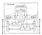
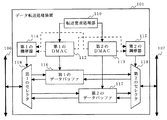
従来のDMA転送方式によるデータ転送処理装置の構成例を、図12に示す。図12において、従来のデータ転送処理装置101は、転送要求処理部110と、第1のダイレクト・メモリ・アクセス・コントローラ(DMAC)112と、第2のDMAC113と、第1の調停器114と、第2の調停器115と、第1のデータバッファ116と、第2のデータバッファ117と、第1のセレクタ118と、第2のセレクタ119とを備える。データ転送処理装置101は、第1のシステムバス106及び第2のシステムバス107に接続され、双方のシステムバス間に発生するデータ転送処理を実行する。
An example of the configuration of a conventional data transfer processing apparatus using the DMA transfer method is shown in FIG. In FIG. 12, a conventional data
転送要求処理部110は、内部又は外部からデータ転送の必要が生じると、第1のDMAC112及び/又は第2のDMAC113に対して、DMA転送要求を与える。第1のDMAC112は、DMA転送要求に応じて、第1のデータバッファ116及び第1の調停器114を制御する。第2のDMAC113は、DMA転送要求に応じて、第2のデータバッファ117及び第2の調停器115を制御する。第1の調停器114は、第1のDMAC112及び第2のDMAC113による制御に基づいて、第1のセレクタ118の選択動作を調停する。第2の調停器15は、第1のDMAC112及び第2のDMAC13による制御に基づいて、第2のセレクタ119の選択動作を調停する。第1のセレクタ118は、第1の調停器114の調停内容に従って、第1のシステムバス106へのアクセス、及び第1のデータバッファ116又は第2のデータバッファ117への選択を実行する。第2のセレクタ119は、第2の調停器115の調停内容に従って、第2のシステムバス107へのアクセス、及び第1のデータバッファ116又は第2のデータバッファ117への選択を実行する。第1のデータバッファ116及び第2のデータバッファ117は、転送されるデータが一時的に書き込まれる記憶領域である。
The transfer
通常、複数のDMACを持つデータ転送処理装置では、図12に示すように、システムバス間の周波数やプロトコルの差を緩衝させるためのデータバッファ116及び117が、DMAC112及び113毎にそれぞれ専用で割り当てられる構成を用いる。この構成によるデータ転送処理装置101おいて、例えば第1のDMAC112を使用して第1のシステムバス106から第2のシステムバス107へのデータ転送を行う場合を考える。この場合には、次の2つのデータ転送方法が考えられる。
Normally, in a data transfer processing device having a plurality of DMACs, as shown in FIG. 12,
第1のデータ転送方法では、第1のDMAC112は、第1のシステムバス106のアクセス権を獲得して、第1のシステムバス106から入力する所定量のデータを第1のデータバッファ116に格納する。そして、データ格納後に、第1のDMAC112は、第2のシステムバス107のアクセス権を獲得して、第1のデータバッファ116に格納されたデータを第2のシステムバス107に出力する。
第2のデータ転送方法では、第1のDMAC112は、第1のシステムバス106のアクセス権を獲得して、第1のシステムバス106から入力する所定量のデータを第1のデータバッファ116に順次格納していく。ここで、第1のDMAC112は、第1のデータバッファ116にデータが格納しながら第2のシステムバス107のアクセス権を獲得して、第1のデータバッファ116に格納済みのデータを順次第2のシステムバス107に出力する。
In the first data transfer method, the first DMAC 112 acquires the right to access the
In the second data transfer method, the first DMAC 112 acquires the access right of the
しかし、上記第1のデータ転送方法の場合、第1のデータバッファ116に格納された全てのデータを第2のシステムバス107に出力し終わるまでは、第1のデータバッファ116に新たなデータを格納することができない。このため、システムバスの効率的な利用ができず、大量のデータを転送する場合等には、実用性に欠ける。
また、上記第2のデータ転送方法の場合、第1のシステムバス106及び第2のシステムバス107両方のアクセス権を、1つのDMAC112が長期にわたって獲得し続けるため、実際にはデータ転送が行われない期間にも双方のシステムバスが開放されず、他の処理に影響を与える。この影響を回避するためには、データ転送が行われる期間と行われない期間との境で、その都度アクセス権の獲得又は開放を行う必要があるが、アクセス権を獲得したい時に他の装置が使用していればシステムバスが空くまで待たなければならないという問題もある(例えば、非特許文献1を参照)。
Further, in the case of the second data transfer method, since one
上述したように、従来のDMA転送方式によるデータ転送処理装置では、周波数又はプロトコルが異なるシステムバス間のデータ転送を効率的に行っておらず、また大量のデータを転送する等の場合においてはシステムバスを有効利用できていない。 As described above, the conventional data transfer processing device using the DMA transfer method does not efficiently transfer data between system buses having different frequencies or protocols, and the system is not suitable for transferring a large amount of data. The bus is not being used effectively.
それ故に、本発明の目的は、DMA転送方式によるデータ転送において、データ転送効率の向上及びシステムバスの使用効率の向上を図った、データ転送処理装置及びデータ転送処理方法を提供することである。 SUMMARY OF THE INVENTION Therefore, an object of the present invention is to provide a data transfer processing device and a data transfer processing method that improve data transfer efficiency and use efficiency of a system bus in data transfer by a DMA transfer method.
本発明は、異なるプロトコル又は周波数で動作する複数のシステムバス間において、ダイレクト・メモリ・アクセス転送方式によるデータ転送を実行するデータ転送処理装置に向けられている。そして、上記目的を達成させるために、本発明のデータ転送処理装置は、複数のデータバッファ、複数のダイレクト・メモリ・アクセス・コントローラ(DMAC)と及びバッファ割り当て部を備える。
複数のデータバッファは、転送データを一時的に格納する。複数のDMACは、データバッファの少なくとも1つを用いて、システムバス間のデータ転送を実行する。バッファ割り当て部は、データ転送状態に応じて、複数のDMACが使用するデータバッファを動的に割り当てる。
The present invention is directed to a data transfer processing device that executes data transfer by a direct memory access transfer method between a plurality of system buses operating with different protocols or frequencies. In order to achieve the above object, the data transfer processing device of the present invention includes a plurality of data buffers, a plurality of direct memory access controllers (DMAC), and a buffer allocation unit.
The plurality of data buffers temporarily store transfer data. The plurality of DMACs perform data transfer between the system buses using at least one of the data buffers. The buffer allocation unit dynamically allocates data buffers used by a plurality of DMACs according to the data transfer state.
好ましいバッファ割り当て部は、複数のDMACのそれぞれについて、データ転送に使用できるデータバッファが1つであるシングルモード又は複数であるマルチモードを、転送されるデータの種別に基づいて設定する転送モード設定部を構成に含む。この構成により、複数のDMACは、転送モード設定部の設定モードに従って、各々のデータ転送に使用可能なデータバッファを決定することができる。
また、他の好ましいバッファ割り当て部は、複数のDMACのそれぞれについて、実際にデータ転送に使用しているデータバッファに関する情報を設定するステータス設定部を構成に含む。この構成により、データ転送を実行しようとするDMACは、ステータス設定部に設定された情報に従って、自己のデータ転送に使用可能なデータバッファを決定することが可能となる。
A preferred buffer allocating unit sets a single mode or a plurality of multimodes in which a single data buffer can be used for data transfer for each of a plurality of DMACs based on the type of data to be transferred. Is included in the configuration. With this configuration, the plurality of DMACs can determine data buffers that can be used for each data transfer according to the setting mode of the transfer mode setting unit.
Another preferable buffer allocating unit includes a status setting unit that sets information on a data buffer actually used for data transfer for each of the plurality of DMACs. With this configuration, the DMAC that intends to execute data transfer can determine a data buffer that can be used for its own data transfer in accordance with the information set in the status setting unit.
このとき、バッファ割り当て部が、使用可能なデータバッファの使用権を調停するデータバッファ調停制御部をさらに構成に含んでもよい。この構成により、データ転送を実行しようとするDMACは、ステータス設定部に設定された情報に従って直ちにデータ転送が開始できない場合でも、データバッファ調停制御部によって与えられる使用権に従って、自己のデータ転送に使用可能なデータバッファを決定することが可能となる。
また、複数のDMACに、それぞれ、データ転送実行中にデータ転送相手の装置によって転送が中断された回数を記憶する遮断回数保持部を含ませて、データバッファを2つ以上使用しているDMACは、遮断回数保持部が記憶する回数が所定の回数に達した場合、使用しているデータバッファの数を減少させてもよい。
At this time, the buffer allocation unit may further include a data buffer arbitration control unit that arbitrates the right to use the usable data buffer. With this configuration, the DMAC that intends to execute data transfer uses it for its own data transfer according to the usage right given by the data buffer arbitration control unit, even if the data transfer cannot be started immediately according to the information set in the status setting unit. It is possible to determine possible data buffers.
A DMAC that uses two or more data buffers includes a plurality of DMACs that each include a shut-off number holding unit that stores the number of times transfer is interrupted by a data transfer partner device during data transfer. When the number of times stored by the shut-off number holding unit reaches a predetermined number, the number of data buffers being used may be decreased.
なお、複数のデータバッファを、格納領域を任意に区分して使用するマルチポートのデータバッファで構成することも可能である。この場合には、バッファ割り当て部は、データ転送を要求する装置毎に、データ転送に必要なデータバッファの段数及び構成に関する情報を予め記憶したバッファ領域対応テーブルと、DMACに割り当てるマルチポートのデータバッファの格納領域区分を、バッファ領域対応テーブルの記憶情報に基づいて制御するバッファ領域管理部との構成を含むことが好ましい。これらの構成により、データ転送を実行しようとするDMACは、バッファ領域管理部によって区分されるエリアを、自己のデータ転送に使用可能なデータバッファとして決定することができる。 Note that the plurality of data buffers may be configured as multi-port data buffers that are used by arbitrarily dividing the storage area. In this case, the buffer allocation unit includes a buffer area correspondence table in which information on the number and configuration of data buffers necessary for data transfer is stored in advance for each device that requests data transfer, and a multiport data buffer allocated to the DMAC. Preferably, the storage area section includes a configuration with a buffer area management unit that controls the storage area division based on the storage information of the buffer area correspondence table. With these configurations, a DMAC that intends to perform data transfer can determine an area partitioned by the buffer area management unit as a data buffer that can be used for its own data transfer.
また、本発明は、転送データを一時的に格納する複数のデータバッファと、データバッファの少なくとも1つを用いて、システムバス間のデータ転送を実行する複数のDMACとを備えた装置が、異なるプロトコル又は周波数で動作する複数のシステムバス間において、DMA転送方式によるデータ転送を実行するデータ転送処理方法に向けられている。そして、上記目的を達成させるために、本発明のデータ転送処理方法では、システムバス上のデータ転送状態を判断し、この判断に応じて複数のDMACが使用するデータバッファを動的に割り当て、この割り当てられたデータバッファを使用してデータ転送を実行する。 Further, the present invention is different in an apparatus including a plurality of data buffers for temporarily storing transfer data and a plurality of DMACs for performing data transfer between system buses using at least one of the data buffers. The present invention is directed to a data transfer processing method for executing data transfer by a DMA transfer method between a plurality of system buses operating at a protocol or frequency. In order to achieve the above object, in the data transfer processing method of the present invention, the data transfer state on the system bus is determined, and data buffers used by a plurality of DMACs are dynamically allocated according to this determination. Perform data transfer using the allocated data buffer.
上記のように、本発明によれば、転送すべきデータの種類に応じて、各DMACがデータ転送に使用するデータバッファの数をシングル又はマルチに切り替えることができる。従って、データ転送効率の向上及びシステムバスの使用効率の向上を図ることができるという効果を発揮する。特に、各DMACの動作状態を表すステータス設定部を用いれば、転送要求処理部の処理負荷を軽減させることができる。また、使用していないデータバッファの使用権を調停するデータバッファ調停制御部を用いることで、データバッファを使用しているDMACのデータ転送の終了を待たなくても、空きデータバッファによるデータ転送を迅速に開始することが可能となる。また、データ転送相手の装置からの特定の応答(中断応答)を所定の回数以上受信した場合にデータバッファの使用権を制御するので、途中でデータ転送効率が悪くなった場合は、バッファ構成を動的に変更して他のデータ転送を並行して行うことができる。さらに、マルチポートのデータバッファに対しては、転送要求されるデータに応じてエリア区分を変更するので、他のDMAC用のデータバッファの使用状態にかかわらず、要求されたデータ転送に最適なデータバッファ構成でデータ転送を行うことが可能となる。 As described above, according to the present invention, the number of data buffers used by each DMAC for data transfer can be switched between single and multiple according to the type of data to be transferred. Therefore, it is possible to improve data transfer efficiency and use efficiency of the system bus. In particular, if a status setting unit representing the operation state of each DMAC is used, the processing load on the transfer request processing unit can be reduced. In addition, by using a data buffer arbitration control unit that arbitrates the right to use unused data buffers, data transfer by an empty data buffer can be performed without waiting for the completion of data transfer of the DMAC that uses the data buffer. It is possible to start quickly. Also, since the right to use the data buffer is controlled when a specific response (interrupt response) from the data transfer partner device is received a predetermined number of times or more, if the data transfer efficiency deteriorates during the process, the buffer configuration can be changed. Other data transfers can be performed in parallel with dynamic changes. In addition, for multi-port data buffers, the area division is changed according to the data requested to be transferred, so that the optimum data for the requested data transfer can be obtained regardless of the use state of the other data buffers for DMAC. Data transfer can be performed with a buffer configuration.
本発明のデータ転送処理装置は、異なるプロトコル又は周波数で動作する複数のシステムバス間でデータ転送の実行が可能である。以下の各実施形態では、2つのシステムバス間でデータ転送を実行する場合を一例に挙げて、本発明のデータ転送処理装置を説明する。また、各実施形態では、双方のシステムバスがデータ転送処理装置外に構成される例を説明するが、データ転送処理装置が終端装置である場合には、いずれか一方のシステムバスがデータ転送処理装置内に構成されることになる。 The data transfer processing device of the present invention can execute data transfer between a plurality of system buses operating with different protocols or frequencies. In the following embodiments, the data transfer processing device of the present invention will be described by taking as an example the case of executing data transfer between two system buses. In each embodiment, an example in which both system buses are configured outside the data transfer processing device will be described. However, when the data transfer processing device is a termination device, either one of the system buses performs data transfer processing. It will be configured in the device.
(第1の実施形態)
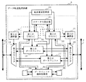
図1は、本発明の第1の実施形態に係るデータ転送処理装置1の構成を示すブロック図である。図1において、第1の実施形態に係るデータ転送処理装置1は、転送要求処理部10と、転送モード設定部11と、第1のDMAC12と、第2のDMAC13と、第1の調停器14と、第2の調停器15と、第1のデータバッファ16と、第2のデータバッファ17と、第1のセレクタ18と、第2のセレクタ19とを備える。データ転送処理装置1は、第1のシステムバス6及び第2のシステムバス7に接続され、双方のシステムバス間に発生するデータ転送処理を実行する。典型的な転送要求処理部10は、デジタル信号プロセッサ(DSP)、中央演算処理装置(CPU)、及びプログラムメモリ(ROM)等で構成されるが、本発明のデータ転送処理装置(以下の各実施形態において同様)は、この構成に限られるものではない。例えば、CPUだけがデータ転送処理装置外に構成されてもよいし、転送要求処理部10がデータ転送処理装置外に構成されてもよい。
(First embodiment)
FIG. 1 is a block diagram showing a configuration of a data
まず、データ転送処理装置1の各構成の概要を説明する。
転送要求処理部10は、内部又は外部からデータ転送の必要が生じると、第1のDMAC12及び/又は第2のDMAC13に対してDMA転送要求を与えると共に、転送モード設定部11への所定の転送モードを設定する。転送モード設定部11は、転送要求処理部10からの指示に従って、第1のデータバッファ16及び第2のデータバッファ17を両方使用するのか、いずれか一方を使用するのか、を与える転送モードを設定する。すなわち、転送モード設定部11は、バッファ割り当て部として機能する。この転送モード設定部11には、レジスタ等が用いられる。第1のDMAC12は、DMA転送要求及び転送モード設定部11に設定された転送モードに基づいて、第1の調停器14、第1のデータバッファ16、及び第2のデータバッファ17を制御する。第2のDMAC13は、DMA転送要求及び転送モード設定部11に設定された転送モードに基づいて、第2の調停器15、第1のデータバッファ16、及び第2のデータバッファ17を制御する。第1の調停器14は、第1のDMAC12及び第2のDMAC13による制御に基づいて、第1のセレクタ18の選択動作を調停する。第2の調停器15は、第1のDMAC12及び第2のDMAC13による制御に基づいて、第2のセレクタ19の選択動作を調停する。第1のセレクタ18は、第1の調停器14の調停内容に従って、システムバス6へのアクセス、及び第1のデータバッファ16又は第2のデータバッファ17の選択を実行する。第2のセレクタ19は、第2の調停器15の調停内容に従って、システムバス7へのアクセス、及び第1のデータバッファ16又は第2のデータバッファ17への選択を実行する。第1のデータバッファ16及び第2のデータバッファ17は、転送されるデータが一時的に書き込まれる記憶領域である。
First, the outline of each configuration of the data
The transfer
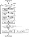
次に、上記構成によるデータ転送処理装置1の処理動作を、図2及び図3をさらに参照して説明する。図2は、第1の実施形態に係るデータ転送処理装置1が実行するデータ転送処理方法の手順を示すフローチャートである。図2の処理は、転送要求処理部10において新たなデータ転送の必要が生じると開始される。
Next, the processing operation of the data
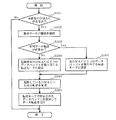
まず、転送要求処理部10は、データ転送を行っていない未使用のDMAC、すなわち起動していないDMACが存在するか否かを判断する(ステップS201)。未使用のDMACが存在する場合、転送要求処理部10は、新たに転送が要求されているデータ、またすでにデータ転送が行われている場合にはそのデータの種類を確認する(ステップS202)。そして、この確認の結果から、転送要求処理部10は、並列的なデータ転送が必要か否かを判断する(ステップS203)。例えば、転送すべきデータが、静止画表示用の画面フレームデータと演算処理用データという異なる2種類である場合には、並列的なデータ転送が必要であると判断される。また、転送すべきデータが、動画表示用の高速大容量のデータの1種類である場合には、並列的なデータ転送が不必要であると判断される。
First, the transfer
並列的なデータ転送が必要であると判断した場合、転送要求処理部10は、ステップS201で判断した未使用のDMACを起動させると共に、第1のDMAC12に第1のデータバッファ16を、第2のDMAC13に第2のデータバッファ17を、それぞれ割り当てる転送モード(シングルバッファモード)を転送モード設定部11に設定する(ステップS204)。一方、並列的なデータ転送が不必要であると判断した場合、転送要求処理部10は、現在起動している第1のDMAC12又は第2のDMAC13に、第1のデータバッファ16及び第2のデータバッファ17の両方を割り当てる転送モード(マルチバッファモード)を転送モード設定部11に設定する(ステップS205)。その後、転送要求処理部10は、起動しているDMACに対してDMA転送要求を与える(ステップS206)。
If it is determined that parallel data transfer is necessary, the transfer
DMA転送要求を受けた第1のDMAC12及び/又は第2のDMAC13は、転送モード設定部11に設定された転送モードに従って、そこで指示されたデータバッファを用いてデータ転送を実行する(ステップS207)。なお、上記ステップS201において未使用のDMACが存在しない場合には、データ転送要求に応えられないため、この処理を終了させる。
The
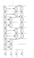
図3は、マルチバッファモードによって第1のDMAC12が実行するデータ転送の一例を説明する図である。図3に示すように、このマルチバッファモードでは、第1のデータバッファ16に格納されたデータの転送が開始されると同時に、第2のデータバッファ17を用いて後続するデータを格納することが可能となる。第2のデータバッファ17に格納されたデータの転送は、第1のデータバッファ16に格納されたデータの転送が完了後に開始される。逆に、第2のデータバッファ17に格納されたデータの転送が開始されると同時に、第1のデータバッファ16を用いてさらに後続するデータを格納することが可能となる。以後、転送すべきデータが終了するまで、この処理が繰り返し行われる。このマルチバッファモードでは、シングルバッファモードに比べて、高速にデータ転送を行うことができる。
FIG. 3 is a diagram for explaining an example of data transfer executed by the
以上のように、本発明の第1の実施形態に係るデータ転送処理装置及び方法によれば、転送すべきデータの種類に応じて、各DMACがデータ転送に使用するデータバッファの数をシングル又はマルチに切り替えることができる。これにより、異なる2種類のデータの並列転送や、大容量データの高速転送といった、システムが要求するデータ転送を適切に行うことが可能となる。従って、データ転送効率の向上及びシステムバスの使用効率の向上を図ることができる。 As described above, according to the data transfer processing device and method according to the first embodiment of the present invention, the number of data buffers used by each DMAC for data transfer is single or You can switch to multi. As a result, data transfer required by the system such as parallel transfer of two different types of data and high-speed transfer of large-capacity data can be appropriately performed. Therefore, it is possible to improve data transfer efficiency and use efficiency of the system bus.
(第2の実施形態)
図4は、本発明の第2の実施形態に係るデータ転送処理装置2の構成を示すブロック図である。図4において、第2の実施形態に係るデータ転送処理装置2は、転送要求処理部20と、ステータス設定部21と、第1のDMAC22と、第2のDMAC23と、第1の調停器14と、第2の調停器15と、第1のデータバッファ16と、第2のデータバッファ17と、第1のセレクタ18と、第2のセレクタ19とを備える。図4に示すように、第2の実施形態に係るデータ転送処理装置2の構成は、上記第1の実施形態に係るデータ転送処理装置1の構成に対して、転送要求処理部20、ステータス設定部21、第1のDMAC22及び第2のDMAC23が異なる。以下、この異なる構成部分を中心に、第2の実施形態に係るデータ転送処理装置2を説明する。
(Second Embodiment)
FIG. 4 is a block diagram showing the configuration of the data
転送要求処理部20は、内部又は外部からデータ転送の必要が生じると、第1のDMAC22及び/又は第2のDMAC23に対してDMA転送要求を与える。ステータス設定部21は、第1のDMAC22及び第2のDMAC23について、データ転送を実行しているか否かや、どのデータバッファを使用してデータ転送を行っているか等の動作状態を設定する。すなわち、ステータス設定部21は、バッファ割り当て部として機能する。このステータス設定部21には、レジスタ等が用いられる。第1のDMAC22は、DMA転送要求及びステータス設定部21に設定された動作状態に基づいて、第1の調停器14、第1のデータバッファ16及び第2のデータバッファ17とを制御する。第2のDMAC23は、DMA転送要求及びステータス設定部21に設定された動作状態に基づいて、第2の調停器15、第1のデータバッファ16及び第2のデータバッファ17とを制御する。
The transfer
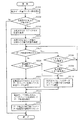
図5は、第2の実施形態に係るデータ転送処理装置2が実行するデータ転送処理方法の手順を示すフローチャートである。図5の処理は、転送要求処理部20において新たなデータ転送の必要が生じると開始される。
FIG. 5 is a flowchart illustrating a procedure of a data transfer processing method executed by the data
まず、転送要求処理部20は、転送するデータ量のしきい値を、第1のDMAC22及び第2のDMAC23に設定する(ステップS501)。このしきい値は、各々のDMACが、2つのデータバッファを用いて(マルチバッファ)並列的にデータ転送を行うのか、1つのデータバッファを用いて(シングルバッファ)通常のデータ転送を行うのかを、判断するために用いられる。その後、転送要求処理部20は、データ転送を行っていない未使用のDMAC、すなわち起動していないDMACが存在するか否かを判断する(ステップS502)。未使用のDMACが存在する場合、転送要求処理部10は、未使用のDMACの1つに対してDMA転送要求を与える(ステップS503)。この実施例では、未使用のDMACを第1のDMAC22として説明する。DMA転送要求を与えられた第1のDMAC22は、ステータス設定部21に設定された動作状態を確認し、他方の第2のDMAC23がデータ転送を行っているか否かと、マルチバッファ又はシングルバッファのどちらでデータ転送を実行しているかをチェックする(ステップS504)。
First, the transfer
チェックの結果、第1のDMAC22は、第2のDMAC23がデータ転送を行っていない場合、DMA転送要求で要求されたデータ転送量が、設定されたしきい値以上であれば第1のデータバッファ16及び第2のデータバッファ17の両方を自分に割り当てる(マルチバッファ)転送モードを、しきい値未満であれば第1のデータバッファ16だけを自分に割り当てる(シングルバッファ)転送モードを、ステータス設定部21に設定する(ステップS505〜S507、S510)。これに対し、第1のDMAC22は、第2のDMAC23がデータ転送を行っている場合、そのデータ転送がシングルバッファで実行されており、かつ、DMA転送要求で要求されたデータ転送量が設定されたしきい値未満であれば、第1のデータバッファ16だけを自分に割り当てる(シングルバッファ)転送モードをステータス設定部21に設定する(ステップS508〜S510)。それ以外の場合には、第1のDMAC22は、第2のDMAC23のデータ転送が終了するまで、すなわち第2のデータバッファ17が空くまで待機することになる。
As a result of the check, if the
第1のDMAC22及び/又は第2のDMAC23は、ステータス設定部21に設定された動作状態に従って、指示されたデータバッファを用いてデータ転送を実行する(ステップS511)。そして、データ転送が終了した後、第1のDMAC22又は第2のDMAC23は、ステータス設定部21に設定している動作状態をリセットする(ステップS512)。なお、上記ステップS502において未使用のDMACが存在しない場合には、データ転送要求に応えられないため、この処理を終了させる。
The
以上のように、本発明の第2の実施形態に係るデータ転送処理装置及び方法によれば、各DMACの動作状態を表すステータス設定部を用いて、一方のDMAC自らが他方のDMACの動作状態を判断して、データ転送に使用するデータバッファをシングル又はマルチに切り替えることができる。従って、上述した第1の実施形態の効果に加えて、転送要求処理部の処理負荷を軽減させることができる。 As described above, according to the data transfer processing device and method according to the second embodiment of the present invention, one DMAC itself uses the status setting unit representing the operation state of each DMAC, and the operation state of the other DMAC And the data buffer used for data transfer can be switched to single or multiple. Therefore, in addition to the effects of the first embodiment described above, the processing load on the transfer request processing unit can be reduced.
(第3の実施形態)
図6は、本発明の第3の実施形態に係るデータ転送処理装置3の構成を示すブロック図である。図6において、第3の実施形態に係るデータ転送処理装置3は、転送要求処理部20と、ステータス設定部21と、第1のDMAC32と、第2のDMAC33と、第1の調停器14と、第2の調停器15と、第1のデータバッファ16と、第2のデータバッファ17と、第1のセレクタ18と、第2のセレクタ19と、データバッファ調停制御部30と、第1のデータバッファステータスフラグ34と、第2のデータバッファステータスフラグ35とを備える。図6に示すように、第3の実施形態に係るデータ転送処理装置3の構成は、上記第2の実施形態に係るデータ転送処理装置2の構成に対して、第1のDMAC32、第2のDMAC33、データバッファ調停制御部30、第1のデータバッファステータスフラグ34及び第2のデータバッファステータスフラグ35が異なる。以下、この異なる構成部分を中心に、第3の実施形態に係るデータ転送処理装置3を説明する。
(Third embodiment)
FIG. 6 is a block diagram showing the configuration of the data
第1のDMAC32は、DMA転送要求及びステータス設定部21に設定された動作状態に基づいて、第1の調停器14、第1のデータバッファ16及び第2のデータバッファ17を制御する。第2のDMAC33は、DMA転送要求及びステータス設定部21に設定された動作状態に基づいて、第2の調停器15、第1のデータバッファ16及び第2のデータバッファ17を制御する。第1のデータバッファステータスフラグ34には、第1のデータバッファ16が使用中である場合にフラグが設定される。第2のデータバッファステータスフラグ35には、第2のデータバッファ17が使用中である場合にフラグが設定される。データバッファ調停制御部30は、第1のデータバッファステータスフラグ34及び第2のデータバッファステータスフラグ35を用いて、第1のデータバッファ16及び第2のデータバッファ17の使用を調停する。このデータバッファ調停制御部30は、ステータス設定部21と共に、バッファ割り当て部として機能する。
The
図7は、第3の実施形態に係るデータ転送処理装置3が実行するデータ転送処理方法の手順を示すフローチャートである。なお、図7において図5に示す処理と同じ処理を実行するステップについては、同一のステップ番号を付してその説明を省略する。
FIG. 7 is a flowchart illustrating a procedure of a data transfer processing method executed by the data
未使用のDMACである第1のDMAC32は、転送要求処理部20からDMA転送要求が与えられると、ステータス設定部21に設定された動作状態を確認し、他方の第2のDMAC33がデータ転送を行っているか否かと、マルチバッファ又はシングルバッファのどちらでデータ転送を実行しているかをチェックする(ステップS704)。これと同時に、第1のDMAC32は、データバッファ調停制御部30に対してデータバッファ使用要求を送出する(ステップS704)。
When a DMA transfer request is given from the transfer
データバッファ使用要求を受けたデータバッファ調停制御部30は、第2のDMAC33がデータ転送を行っており、そのデータ転送がマルチバッファで実行されているか、DMA転送要求で要求されたデータ転送量が設定されたしきい値以上であれば、第1のデータバッファ16だけを自分に割り当てる(シングルバッファ)転送モードをステータス設定部21に設定すると共に(ステップS710)、使用可能なデータバッファの使用権を調停する(ステップS711)。具体的には、データバッファ調停制御部30は、第1のデータバッファ16又は第2のデータバッファ17のどちらかのデータ転送が終了する(データバッファが空く)のを判断して(ステップS712)、空いたデータバッファをさらに調停する(ステップS713)。例えば、第1のデータバッファ16が終了した場合には、データバッファ調停制御部30は、第2のDMAC33による第1のデータバッファ16の使用権をクリアする。これにより、第2のDMAC33は、シングルデータバッファ構成で続きのデータ転送を行う。また、データバッファ調停制御部30は、第2のDMAC33から開放された第1のデータバッファ16の使用権を第1のDMAC32に許可する。これにより、第1のDMAC32は、新たなデータ転送の開始が可能となる。なお、この調停処理に応じて、ステータス設定部21の設定が更新される(ステップS713)。
In response to the data buffer use request, the data buffer
以上のように、本発明の第3の実施形態に係るデータ転送処理装置及び方法によれば、使用していないデータバッファの使用権を調停するデータバッファ調停制御部を用いる。これにより、一方のDMACが複数のデータバッファを占有してデータ転送を行っていたとしても、途中に発生するデータバッファ未使用の期間を他方のDMACに一時的に転用させることが可能となる。従って、一方のDMACのデータ転送の終了を待たなくても、空きデータバッファによるデータ転送を迅速に開始することが可能となる。
なお、データバッファの開放を許可させないために、各DMACからデータバッファ調停制御部30へデータバッファ使用要求を出す際に、要求と共にデータ転送の優先度も通知させてもよい。
As described above, according to the data transfer processing device and method according to the third embodiment of the present invention, the data buffer arbitration control unit that arbitrates the use right of the unused data buffer is used. As a result, even when one DMAC occupies a plurality of data buffers and performs data transfer, it is possible to temporarily divert the unused period of the data buffer to the other DMAC. Therefore, it is possible to quickly start data transfer by the empty data buffer without waiting for the end of data transfer of one DMAC.
In order not to allow the release of the data buffer, when a data buffer use request is issued from each DMAC to the data buffer
(第4の実施形態)
図8は、本発明の第4の実施形態に係るデータ転送処理装置4の構成を示すブロック図である。図8において、第4の実施形態に係るデータ転送処理装置4は、転送要求処理部20と、ステータス設定部21と、第1のDMAC42と、第2のDMAC43と、第1の調停器14と、第2の調停器15と、第1のデータバッファ16と、第2のデータバッファ17と、第1のセレクタ18と、第2のセレクタ19と、データバッファ調停制御部30と、第1のデータバッファステータスフラグ34と、第2のデータバッファステータスフラグ35とを備える。図8に示すように、第4の実施形態に係るデータ転送処理装置4の構成は、上記第3の実施形態に係るデータ転送処理装置3の構成に対して、第1のDMAC42及び第2のDMAC43が異なる。以下、この異なる構成部分を中心に、第4の実施形態に係るデータ転送処理装置4を説明する。
(Fourth embodiment)
FIG. 8 is a block diagram showing the configuration of the data
第1のDMAC42は、上述した第1のDMAC32内に遮断回数保持部421を有する構成である。第2のDMAC43は、上述した第2のDMAC33内に遮断回数保持部431を有する構成である。この遮断回数保持部421及び431は、第1のDMAC42及び第2のDMAC43が、システムバス6又は7にデータ転送を行おうとした際に、データ転送相手の装置によって何度中断されたかをデータバッファ単位でカウントして保持する。この遮断回数保持部421及び431は、レジスタ等が用いられる。
The
転送要求処理部20が、必要に応じて第1のDMAC42及び第2のDMAC43にDMA転送を要求し、要求された第1のDMAC42及び第2のDMAC43が、データ転送を開始する。今、第1のDMAC42が、システムバス6からシステムバス7へ、第1のデータバッファ16及び第2のデータバッファ17の両方を占有したデータ転送を開始した場合で説明する。ここで、システムバス6が、PCIバスのような連続転送と転送遮断が発生するバスであった場合、システムバス6からデータを第1のデータバッファ16へ格納中に、データ転送相手の装置から転送の一時中断を受ける場合がある。これは、データ転送相手の装置側の先読み出しデータバッファ(プリフェッチFIFO等)の段数や、内部処理の状態に依存する。第1のDMAC42は、転送中断回数を遮断回数保持部421へカウントして保持し、予め定めた回数と比較する。予め定めた回数を超える転送中断が発生したときに、第1のデータバッファ16及び第2のデータバッファ17を並列的に使用している場合、第1のDMAC42は、どちらか一方のデータバッファを開放する。このとき、第2のDMAC43に新たなデータ転送が要求が発生している場合には、直ちに開放したデータバッファを用いてデータ転送を開始する。
The transfer
以上のように、本発明の第4の実施形態に係るデータ転送処理装置及び方法によれば、遮断回数保持部を用いて、データ転送相手の装置からの特定の応答を所定の回数以上受信した場合に、データバッファの使用権を制御する。これにより、優先度の高いデータ転送であっても、途中でデータ転送効率が悪くなった場合は、バッファ構成を動的に変更して、他のデータ転送を並行して行うことができる。よって、システム全体のデータ転送効率を高めることが可能となる。 As described above, according to the data transfer processing device and method of the fourth embodiment of the present invention, a specific response from the data transfer partner device is received a predetermined number of times or more using the block count holding unit. Control the right to use the data buffer. As a result, even if the data transfer has a high priority, if the data transfer efficiency deteriorates during the process, the buffer configuration can be dynamically changed to perform other data transfers in parallel. Therefore, it is possible to increase the data transfer efficiency of the entire system.
(第5の実施形態)
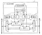
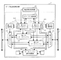
図9は、本発明の第5の実施形態に係るデータ転送処理装置5の構成を示すブロック図である。図9において、第5の実施形態に係るデータ転送処理装置5は、転送要求処理部20と、第1のDMAC52と、第2のDMAC53と、バッファ領域対応テーブル54と、バッファ領域管理部55と、第1の調停器14と、第2の調停器15と、データバッファ56と、第1のセレクタ58と、第2のセレクタ59とを備える。図9に示すように、第5の実施形態に係るデータ転送処理装置5の構成は、上記第2の実施形態に係るデータ転送処理装置2の構成に対して、第1のDMAC52、第2のDMAC53、バッファ領域対応テーブル54、バッファ領域管理部55、データバッファ56、第1のセレクタ58及び第2のセレクタ59が異なる。以下、この異なる構成部分を中心に、第5の実施形態に係るデータ転送処理装置2を説明する。
(Fifth embodiment)
FIG. 9 is a block diagram showing the configuration of the data
第1のDMAC52は、バッファ領域対応テーブル54を参照して、第1の調停器14及びデータバッファ56を制御する。第2のDMAC53は、バッファ領域対応テーブル54を参照して、第2の調停器15及びデータバッファ56を制御する。バッファ領域対応テーブル54は、データの転送を要求したデータ転送元の装置に関する情報、例えばベースアドレスと、そのデータ転送元の装置に最適なデータバッファ構成とを保持する。バッファ領域管理部55は、データバッファ56のアドレス制御を行って、第1のDMAC52及び第2のDMAC53が使用するバッファ領域を管理する。すなわち、バッファ領域対応テーブル54及びバッファ領域管理部55は、バッファ割り当て部として機能する。第1のセレクタ58は、第1の調停器14の調停内容に従って、システムバス6へのアクセス、及びデータバッファ56の第1のDMAC52用ポート又は第2のDMAC53用ポートの選択を実行する。第2のセレクタ59は、第2の調停器15の調停内容に従って、システムバス6へのアクセス、及びデータバッファ56の第1のDMAC52用ポート又は第2のDMAC53用ポートの選択を実行する。データバッファ56は、格納領域を任意に区切って使用するマルチポートのデータバッファである。
The
図10は、第5の実施形態に係るデータ転送処理装置5が実行するデータ転送処理方法の手順を示すフローチャートである。図10の処理は、転送要求処理部20において新たなデータ転送の必要が生じると開始される。
FIG. 10 is a flowchart illustrating a procedure of a data transfer processing method executed by the data
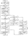
まず、転送要求処理部20は、データ転送を行っていない未使用のDMAC、すなわち起動していないDMACが存在するか否かを判断する(ステップS1001)。未使用のDMACが存在する場合、転送要求処理部20は、未使用のDMACを起動させて、DMA転送要求を与える(ステップS1002)。この実施例では、未使用のDMACを第1のDMAC52として説明する。DMA転送要求を受けた第1のDMAC52は、バッファ領域対応テーブル54を参照して、データバッファ56における最適なデータバッファ構成を決定し、バッファ領域管理部55に通知する(ステップS1003)。最適なデータバッファ構成は、データ転送元の装置のベースアドレスに基づいて決定される。バッファ領域管理部55は、第1のDMAC52からの通知を受けて、データバッファ56の未使用領域を通知内容に応じて第1のDMAC52用に割り当て、割り当てた旨を第1のDMAC52に応答する(ステップS1004)。
First, the transfer
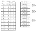
図11に、バッファ領域対応テーブル54の情報及びデータバッファ56の割り当て例を示す。図11のように、データバッファ56の格納領域がバッファ[0]〜[15]で構成される場合、バッファ領域対応テーブル54には、バッファ[0]〜[15]のそれぞれについて割り当てるDMAC及びエリアが記述される。データバッファ56は、このバッファ領域対応テーブル54の記述内容に従って、エリアが区分されることになる。
FIG. 11 shows an example of allocation of the buffer area correspondence table 54 and the
転送要求処理部20は、転送が要求されているデータの種類を確認する(ステップS1005)。そして、この確認の結果から、転送要求処理部20は、並列的なデータ転送が必要か否かを判断する(ステップS1006)。この判断に従って、第1のDMAC52は、データバッファ領域を2つ使用して並列転送又は1つ使用した通常転送を実行する(ステップS1007、S1008)。
The transfer
以上のように、本発明の第5の実施形態に係るデータ転送処理装置及び方法によれば、任意のエリアで格納領域を区分できる1つの大きなマルチポートのデータバッファを用い、転送要求されるデータ量に応じてエリア区分を変更する。これにより、例えば連続転送可能データ量が長い場合には、それに併せてデータバッファ内に大きなエリアを確保し、短い場合には、小さいエリアで済む。従って、他のDMAC用のデータバッファの使用状態にかかわらず、要求されたデータ転送に最適なデータバッファ構成でデータ転送を行うことが可能となる。 As described above, according to the data transfer processing device and method according to the fifth embodiment of the present invention, the data requested to be transferred using one large multi-port data buffer capable of partitioning the storage area in an arbitrary area. Change area classification according to quantity. Thus, for example, when the continuous transferable data amount is long, a large area is secured in the data buffer, and when it is short, a small area is sufficient. Therefore, it is possible to perform data transfer with a data buffer configuration optimum for the requested data transfer regardless of the use state of other DMAC data buffers.
なお、本発明のデータ転送処理装置を構成する転送モード設定部、ステータス設定部、DMAC、調停器、データバッファ、データバッファ調停制御部、セレクタ、プリフェッチ語数設定部、アドレス検索部、語数設定テーブル、データバッファステータスフラグ、遮断回数保持レジスタ、バッファ領域対応テーブル、及びバッファ領域管理部の各機能ブロックは、典型的には集積回路であるLSI(集積度の違いにより、IC、システムLSI、スーパーLSI、又はウルトラLSI等と称される)として実現される。これらは、個別に1チップ化されてもよいし、一部又は全部を含むように1チップ化されてもよい。
また、集積回路化の手法は、LSIに限るものではなく、専用回路又は汎用プロセッサで実現してもよい。また、LSI製造後にプログラムすることが可能なFPGA(Field Programmable Gate Array)や、LSI内部の回路セルの接続や設定を再構成可能なリコンフィギュラブル・プロセッサを利用してもよい。
さらには、半導体技術の進歩又は派生する別の技術により、LSIに置き換わる集積回路化の技術が登場すれば、当然その技術を用いて機能ブロックの集積化を行ってもよい。バイオ技術の適応等が可能性としてあり得る。
The transfer mode setting unit, status setting unit, DMAC, arbiter, data buffer, data buffer arbitration control unit, selector, prefetch word number setting unit, address search unit, word number setting table, which constitute the data transfer processing device of the present invention, Each functional block of the data buffer status flag, the shut-off count holding register, the buffer area correspondence table, and the buffer area management unit is typically an integrated circuit LSI (depending on the degree of integration, IC, system LSI, super LSI, Alternatively, it is realized as an ultra LSI or the like. These may be individually made into one chip, or may be made into one chip so as to include a part or all of them.
Further, the method of circuit integration is not limited to LSI's, and implementation using dedicated circuitry or general purpose processors is also possible. Also, an FPGA (Field Programmable Gate Array) that can be programmed after manufacturing the LSI, or a reconfigurable processor that can reconfigure the connection and setting of circuit cells inside the LSI may be used.
Furthermore, if integrated circuit technology comes out to replace LSI's as a result of the advancement of semiconductor technology or a derivative other technology, it is naturally also possible to carry out function block integration using this technology. There is a possibility of adaptation of biotechnology.
本発明のデータ転送処理装置及びデータ転送処理方法は、異なるプロトコル又は周波数で動作する複数のシステムバス間において、DMA転送方式によるデータ転送を実行する場合等に利用可能であり、特にデータ転送効率の向上及びシステムバスの使用効率の向上を図る場合に適している。 The data transfer processing device and the data transfer processing method of the present invention can be used when data transfer is performed by a DMA transfer method between a plurality of system buses operating with different protocols or frequencies. It is suitable for improving the system bus usage efficiency.
1、2、3、4、5、101 データ転送処理装置
6、7、106、107 システムバス
10、20、110 転送要求処理部
11 転送モード設定部
12、13、22、23、32、33、42、43、52、53、112、113 DMAC(ダイレクトメモリアクセスコントローラ)
14、15、114、115 調停器
16、17、56、116、117 データバッファ
18、19、58、59、118、119 セレクタ
21 ステータス設定部
30 データバッファ調停制御部
34、35 データバッファステータスフラグ
421、431 遮断回数保持部
54 バッファ領域対応テーブル
55 バッファ領域管理部
1, 2, 3, 4, 5, 101 Data
14, 15, 114, 115
Claims (8)
転送データを一時的に格納する複数のデータバッファと、
前記データバッファの少なくとも1つを用いて、システムバス間のデータ転送を実行する複数のダイレクト・メモリ・アクセス・コントローラと、
データ転送状態に応じて、前記複数のダイレクト・メモリ・アクセス・コントローラが使用する前記データバッファを動的に割り当てるバッファ割り当て部とを備える、データ転送処理装置。 A data transfer processing device for executing data transfer by a direct memory access transfer method between a plurality of system buses operating at different protocols or frequencies,
A plurality of data buffers for temporarily storing transfer data; and
A plurality of direct memory access controllers that perform data transfer between system buses using at least one of the data buffers;
A data transfer processing device comprising: a buffer allocation unit that dynamically allocates the data buffer used by the plurality of direct memory access controllers according to a data transfer state.
前記複数のダイレクト・メモリ・アクセス・コントローラは、前記転送モード設定部の設定モードに従って、各々のデータ転送に使用可能な前記データバッファを決定することを特徴とする、請求項1に記載のデータ転送処理装置。 For each of the plurality of direct memory access controllers, the buffer allocating unit sets a single mode or a multi-mode having a single data buffer that can be used for data transfer as a type of data to be transferred. Including a transfer mode setting section to set based on,
The data transfer according to claim 1, wherein the plurality of direct memory access controllers determine the data buffer that can be used for each data transfer according to a setting mode of the transfer mode setting unit. Processing equipment.
データ転送を実行しようとする前記ダイレクト・メモリ・アクセス・コントローラは、前記ステータス設定部に設定された情報に従って、自己のデータ転送に使用可能な前記データバッファを決定することを特徴とする、請求項1に記載のデータ転送処理装置。 The buffer allocation unit includes a status setting unit that sets information on the data buffer that is actually used for data transfer for each of the plurality of direct memory access controllers,
The direct memory access controller attempting to perform data transfer determines the data buffer that can be used for its own data transfer according to information set in the status setting unit. 2. The data transfer processing device according to 1.
データ転送を実行しようとする前記ダイレクト・メモリ・アクセス・コントローラは、前記ステータス設定部に設定された情報に従って直ちにデータ転送が開始できない場合には、前記データバッファ調停制御部によって与えられる使用権に従って、自己のデータ転送に使用可能な前記データバッファを決定することを特徴とする、請求項3に記載のデータ転送処理装置。 The buffer allocation unit further includes a data buffer arbitration control unit that arbitrates the right to use the usable data buffer,
If the direct memory access controller that intends to execute data transfer cannot immediately start data transfer according to the information set in the status setting unit, according to the usage right given by the data buffer arbitration control unit, 4. The data transfer processing device according to claim 3, wherein the data buffer usable for its own data transfer is determined.
前記データバッファを2つ以上使用している前記ダイレクト・メモリ・アクセス・コントローラは、前記遮断回数保持部が記憶する回数が所定の回数に達した場合、使用している前記データバッファの数を減少させることを特徴とする、請求項3又は4に記載のデータ転送処理装置。 Each of the plurality of direct memory access controllers includes a shut-off number holding unit that stores the number of times transfer is interrupted by a data transfer partner device during data transfer execution,
The direct memory access controller using two or more data buffers reduces the number of data buffers in use when the number of times stored in the shut-off count holding unit reaches a predetermined number. The data transfer processing device according to claim 3 or 4, characterized in that:
前記バッファ割り当て部は、
データ転送を要求する装置毎に、データ転送に必要なデータバッファの段数及び構成に関する情報を予め記憶したバッファ領域対応テーブルと、
前記ダイレクト・メモリ・アクセス・コントローラに割り当てる前記マルチポートのデータバッファの格納領域区分を、前記バッファ領域対応テーブルの記憶情報に基づいて制御するバッファ領域管理部とを含み、
データ転送を実行しようとする前記ダイレクト・メモリ・アクセス・コントローラは、前記バッファ領域管理部によって区分されるエリアを、自己のデータ転送に使用可能な前記データバッファとして決定することを特徴とする、請求項1に記載のデータ転送処理装置。 The plurality of data buffers are configured by multi-port data buffers that are used by arbitrarily dividing a storage area,
The buffer allocation unit
For each device that requests data transfer, a buffer area correspondence table that pre-stores information on the number and configuration of data buffer stages necessary for data transfer, and
A buffer area management unit that controls storage area division of the multi-port data buffer assigned to the direct memory access controller based on storage information of the buffer area correspondence table;
The direct memory access controller attempting to execute data transfer determines an area partitioned by the buffer area management unit as the data buffer that can be used for its own data transfer. Item 4. The data transfer processing device according to Item 1.
システムバス上のデータ転送状態を判断するステップと、
前記判断するステップの判断に応じて、前記複数のダイレクト・メモリ・アクセス・コントローラが使用する前記データバッファを動的に割り当てるステップと、
前記割り当てるステップで割り当てられた前記データバッファを使用してデータ転送を実行するステップとを備える、データ転送処理方法。 A device having a plurality of data buffers for temporarily storing transfer data and a plurality of direct memory access controllers for performing data transfer between system buses using at least one of the data buffers is different. A data transfer processing method for executing data transfer by a direct memory access transfer method between a plurality of system buses operating at a protocol or frequency,
Determining the data transfer status on the system bus;
Dynamically allocating the data buffer used by the plurality of direct memory access controllers in response to the determination of the determining step;
Executing data transfer using the data buffer allocated in the allocating step.
転送データを一時的に格納する複数のデータバッファと、
前記データバッファの少なくとも1つを用いて、システムバス間のデータ転送を実行する複数のダイレクト・メモリ・アクセス・コントローラと、
データ転送状態に応じて、前記複数のダイレクト・メモリ・アクセス・コントローラが使用する前記データバッファを動的に割り当てるバッファ割り当て部とを集積した、集積回路。
An integrated circuit of a data transfer processing device that executes data transfer by a direct memory access transfer method between a plurality of system buses operating at different protocols or frequencies,
A plurality of data buffers for temporarily storing transfer data; and
A plurality of direct memory access controllers that perform data transfer between system buses using at least one of the data buffers;
An integrated circuit in which a buffer allocation unit that dynamically allocates the data buffer used by the plurality of direct memory access controllers according to a data transfer state is integrated.
Priority Applications (4)
| Application Number | Priority Date | Filing Date | Title |
|---|---|---|---|
| JP2004110465A JP2005293427A (en) | 2004-04-02 | 2004-04-02 | Data transfer processing apparatus and data transfer processing method |
| DE602005006338T DE602005006338T2 (en) | 2004-04-02 | 2005-03-31 | Apparatus and method for data transmission processing |
| EP05007113A EP1582989B1 (en) | 2004-04-02 | 2005-03-31 | Data transfer processing device and data transfer processing method |
| US11/094,368 US20050223135A1 (en) | 2004-04-02 | 2005-03-31 | Data transfer processing device and data transfer processing method |
Applications Claiming Priority (1)
| Application Number | Priority Date | Filing Date | Title |
|---|---|---|---|
| JP2004110465A JP2005293427A (en) | 2004-04-02 | 2004-04-02 | Data transfer processing apparatus and data transfer processing method |
Publications (1)
| Publication Number | Publication Date |
|---|---|
| JP2005293427A true JP2005293427A (en) | 2005-10-20 |
Family
ID=34880139
Family Applications (1)
| Application Number | Title | Priority Date | Filing Date |
|---|---|---|---|
| JP2004110465A Pending JP2005293427A (en) | 2004-04-02 | 2004-04-02 | Data transfer processing apparatus and data transfer processing method |
Country Status (4)
| Country | Link |
|---|---|
| US (1) | US20050223135A1 (en) |
| EP (1) | EP1582989B1 (en) |
| JP (1) | JP2005293427A (en) |
| DE (1) | DE602005006338T2 (en) |
Cited By (2)
| Publication number | Priority date | Publication date | Assignee | Title |
|---|---|---|---|---|
| JP2009048427A (en) * | 2007-08-20 | 2009-03-05 | Ricoh Co Ltd | Image processor and image processing method |
| JP2014130587A (en) * | 2012-12-27 | 2014-07-10 | Lsi Corp | Non-volatile memory program failure recovery via redundant arrays |
Families Citing this family (8)
| Publication number | Priority date | Publication date | Assignee | Title |
|---|---|---|---|---|
| US7461183B2 (en) * | 2004-08-03 | 2008-12-02 | Lsi Corporation | Method of processing a context for execution |
| JP5079342B2 (en) * | 2007-01-22 | 2012-11-21 | ルネサスエレクトロニクス株式会社 | Multiprocessor device |
| JP5612807B2 (en) | 2007-03-13 | 2014-10-22 | セイコーエプソン株式会社 | Image transmission method determination method, image supply system, image supply apparatus, program, and computer-readable recording medium |
| US20100169673A1 (en) * | 2008-12-31 | 2010-07-01 | Ramakrishna Saripalli | Efficient remapping engine utilization |
| JP5547701B2 (en) * | 2011-09-21 | 2014-07-16 | 日立オートモティブシステムズ株式会社 | Electronic control unit for automobile |
| US9250666B2 (en) | 2012-11-27 | 2016-02-02 | International Business Machines Corporation | Scalable data collection for system management |
| KR20170056782A (en) * | 2015-11-13 | 2017-05-24 | 에스케이하이닉스 주식회사 | Memory system and operating method for the same |
| CN108345551B (en) * | 2017-01-23 | 2020-05-12 | 杭州海康威视数字技术股份有限公司 | Data storage method and device |
Family Cites Families (16)
| Publication number | Priority date | Publication date | Assignee | Title |
|---|---|---|---|---|
| WO1990004233A1 (en) * | 1988-10-05 | 1990-04-19 | Mentor Graphics Corporation | Method of using electronically reconfigurable gate array logic and apparatus formed thereby |
| US4965717A (en) * | 1988-12-09 | 1990-10-23 | Tandem Computers Incorporated | Multiple processor system having shared memory with private-write capability |
| US5130981A (en) * | 1989-03-22 | 1992-07-14 | Hewlett-Packard Company | Three port random access memory in a network bridge |
| US5852600A (en) * | 1995-06-07 | 1998-12-22 | Mci Communications Corporation | System and method for resolving substantially simultaneous bi-directional requests of spare capacity |
| US5781799A (en) * | 1995-09-29 | 1998-07-14 | Cirrus Logic, Inc. | DMA controller arrangement having plurality of DMA controllers and buffer pool having plurality of buffers accessible to each of the channels of the controllers |
| US5771359A (en) * | 1995-10-13 | 1998-06-23 | Compaq Computer Corporation | Bridge having a data buffer for each bus master |
| JP3712842B2 (en) * | 1997-08-05 | 2005-11-02 | 株式会社リコー | Data transfer control method, data transfer control device, and information recording medium |
| US6067595A (en) * | 1997-09-23 | 2000-05-23 | Icore Technologies, Inc. | Method and apparatus for enabling high-performance intelligent I/O subsystems using multi-port memories |
| US6782465B1 (en) * | 1999-10-20 | 2004-08-24 | Infineon Technologies North America Corporation | Linked list DMA descriptor architecture |
| US6862653B1 (en) * | 2000-09-18 | 2005-03-01 | Intel Corporation | System and method for controlling data flow direction in a memory system |
| JP3680763B2 (en) * | 2001-05-14 | 2005-08-10 | セイコーエプソン株式会社 | Data transfer control device and electronic device |
| US6804741B2 (en) * | 2002-01-16 | 2004-10-12 | Hewlett-Packard Development Company, L.P. | Coherent memory mapping tables for host I/O bridge |
| US6922741B2 (en) * | 2002-02-01 | 2005-07-26 | Intel Corporation | Method and system for monitoring DMA status |
| DE10214700B4 (en) * | 2002-04-03 | 2006-02-23 | Advanced Micro Devices, Inc., Sunnyvale | Combined ATA / SATA controller as integrated circuit chip and associated method of operation |
| US6981072B2 (en) * | 2003-06-05 | 2005-12-27 | International Business Machines Corporation | Memory management in multiprocessor system |
| US8023417B2 (en) * | 2004-08-30 | 2011-09-20 | International Business Machines Corporation | Failover mechanisms in RDMA operations |
-
2004
- 2004-04-02 JP JP2004110465A patent/JP2005293427A/en active Pending
-
2005
- 2005-03-31 DE DE602005006338T patent/DE602005006338T2/en not_active Expired - Fee Related
- 2005-03-31 EP EP05007113A patent/EP1582989B1/en not_active Expired - Fee Related
- 2005-03-31 US US11/094,368 patent/US20050223135A1/en not_active Abandoned
Cited By (4)
| Publication number | Priority date | Publication date | Assignee | Title |
|---|---|---|---|---|
| JP2009048427A (en) * | 2007-08-20 | 2009-03-05 | Ricoh Co Ltd | Image processor and image processing method |
| JP2014130587A (en) * | 2012-12-27 | 2014-07-10 | Lsi Corp | Non-volatile memory program failure recovery via redundant arrays |
| US10467093B2 (en) | 2012-12-27 | 2019-11-05 | Seagate Technology Llc | Non-volatile memory program failure recovery via redundant arrays |
| US11144389B2 (en) | 2012-12-27 | 2021-10-12 | Seagate Technology Llc | Non-volatile memory program failure recovery via redundant arrays |
Also Published As
| Publication number | Publication date |
|---|---|
| DE602005006338T2 (en) | 2009-06-10 |
| DE602005006338D1 (en) | 2008-06-12 |
| EP1582989A1 (en) | 2005-10-05 |
| US20050223135A1 (en) | 2005-10-06 |
| EP1582989B1 (en) | 2008-04-30 |
Similar Documents
| Publication | Publication Date | Title |
|---|---|---|
| JP7313381B2 (en) | Embedded scheduling of hardware resources for hardware acceleration | |
| JP6755935B2 (en) | Shared memory controller and how to use it | |
| US8516163B2 (en) | Hardware-based concurrent direct memory access (DMA) engines on serial rapid input/output SRIO interface | |
| JP4456490B2 (en) | DMA equipment | |
| EP1582989B1 (en) | Data transfer processing device and data transfer processing method | |
| EP1645967A1 (en) | Multi-channel DMA with shared FIFO buffer | |
| EP3352090A1 (en) | Multi-channel dma system with command queue structure supporting three dma modes | |
| JP5578713B2 (en) | Information processing device | |
| JPH06250928A (en) | Information processor | |
| JP5040050B2 (en) | Multi-channel DMA controller and processor system | |
| JP2007080037A (en) | Dma transfer system | |
| JP7470685B2 (en) | Programming and Controlling Computational Units in Integrated Circuits | |
| JP2007102646A (en) | Context switching device | |
| US8756356B2 (en) | Pipe arbitration using an arbitration circuit to select a control circuit among a plurality of control circuits and by updating state information with a data transfer of a predetermined size | |
| JP2009020555A (en) | Swapping device | |
| US20130042043A1 (en) | Method and Apparatus for Dynamic Channel Access and Loading in Multichannel DMA | |
| US20080209085A1 (en) | Semiconductor device and dma transfer method | |
| WO2007039933A1 (en) | Operation processing device | |
| JP2004227501A (en) | Data transfer controller and method | |
| JP2005165592A (en) | Data transfer device | |
| US10540305B2 (en) | Semiconductor device | |
| JP2000227897A (en) | Device and system for dma transfer | |
| JP2005165508A (en) | Direct memory access controller | |
| KR101706201B1 (en) | Direct memory access controller and operating method thereof | |
| JP2007108858A (en) | Pin sharing device and pin sharing method |