JP2005292784A - Photometric device equipped with color measuring function and camera equipped with photometric device - Google Patents
Photometric device equipped with color measuring function and camera equipped with photometric device Download PDFInfo
- Publication number
- JP2005292784A JP2005292784A JP2005004244A JP2005004244A JP2005292784A JP 2005292784 A JP2005292784 A JP 2005292784A JP 2005004244 A JP2005004244 A JP 2005004244A JP 2005004244 A JP2005004244 A JP 2005004244A JP 2005292784 A JP2005292784 A JP 2005292784A
- Authority
- JP
- Japan
- Prior art keywords
- photometric
- filter
- sensor
- block
- unit
- Prior art date
- Legal status (The legal status is an assumption and is not a legal conclusion. Google has not performed a legal analysis and makes no representation as to the accuracy of the status listed.)
- Pending
Links
Images

Landscapes
- Spectrometry And Color Measurement (AREA)
- Photometry And Measurement Of Optical Pulse Characteristics (AREA)
- Exposure Control For Cameras (AREA)
- Color Television Image Signal Generators (AREA)
Abstract
Description
本発明は、測色機能を備えた装置およびその測光装置を備えたカメラに関するものである。 The present invention relates to a device having a colorimetric function and a camera having the photometric device.
従来より、カメラでは測光センサによる測光結果に基づいて自動露光が行われている。このような測光センサには測色機能を備えたものもある(例えば、特許文献1参照)。
上述した測光センサはホワイトバランスや自動露光に関わる条件の設定を目的に用いられ、小型で、測光感度が高いものが好ましい。測光センサの測光感度を増感させるには、測光センサの測光面を大きくすれば良い。
The photometric sensor described above is used for the purpose of setting conditions relating to white balance and automatic exposure, and is preferably small and has high photometric sensitivity. In order to increase the photometric sensitivity of the photometric sensor, the photometric surface of the photometric sensor may be enlarged.
しかし、測光センサを小型化すると、測光面が小さくなり、測光感度が低下してしまう。一方、測光センサの測光面を大きくすると、測光感度を増感させることはできるが、測光センサが大型化してしまう。
本発明は、小型でありながら、測光感度の高い、測色機能を備えた測光装置およびその測光装置を備えたカメラを提供することを目的とする。
However, if the photometric sensor is downsized, the photometric surface becomes small and the photometric sensitivity is lowered. On the other hand, when the photometric surface of the photometric sensor is increased, the photometric sensitivity can be increased, but the photometric sensor is increased in size.
An object of the present invention is to provide a photometric device having a colorimetric function with high photometric sensitivity, and a camera provided with the photometric device.
請求項1に記載の測光装置は、少なくとも550nm近傍の波長域に分光感度を有する第1の測光センサと、赤色波長域に分光感度ピークを有する第2の測光センサと、青色波長域に分光感度ピークを有する第3の測光センサとを有し、各測光センサは測光面にマトリクス状に配列され、かつ、前記第1の測光センサが前記測光面の第1の方向に沿って少なくとも2列に配列された第1のブロックと、前記第2の測光センサと前記第3の測光センサとが前記第1の方向に沿って交互に繰り返し配列された第2のブロックと、前記第1のブロックと同一の配列の第3のブロックと、前記第2のブロックにおける前記第2の測光センサと前記第3の測光センサとが入れ替わった配列の第4のブロックとが、前記第1の方向に直交する第2の方向に沿って順次繰り返し配列されて成り、それぞれの前記測光センサで得られる複数の測光値を出力する測光部と、前記測光部により出力された前記複数の測光値に応じて測色情報と測光情報とを取得する取得部とを備えたことを特徴とする。 The photometric device according to claim 1 includes a first photometric sensor having a spectral sensitivity in a wavelength region near at least 550 nm, a second photometric sensor having a spectral sensitivity peak in a red wavelength region, and a spectral sensitivity in a blue wavelength region. A third photometric sensor having a peak, the photometric sensors are arranged in a matrix on the photometric surface, and the first photometric sensors are arranged in at least two rows along the first direction of the photometric surface. A first block arranged, a second block in which the second photometric sensor and the third photometric sensor are alternately and repeatedly arranged along the first direction, and the first block The third block in the same arrangement and the fourth block in the arrangement in which the second photometry sensor and the third photometry sensor in the second block are interchanged are orthogonal to the first direction. In the second direction A photometric unit that outputs a plurality of photometric values obtained by each of the photometric sensors, and colorimetric information and photometric information according to the photometric values output by the photometric unit. And an acquisition unit for acquiring.
請求項2に記載の測光装置は、請求項1に記載の測光装置において、前記測光部は、前記第1の測光センサとして緑色フィルタを備えた受光部を用いることを特徴とする。
請求項3に記載の測光装置は、請求項1に記載の測光装置において、前記測光部は、前記第1の測光センサとして比視感度フィルタを備えた受光部を用いることを特徴とする。
請求項4に記載の測光装置は、請求項1に記載の測光装置において、前記測光部は、前記第1の測光センサとして黄色の補色フィルタを備えた受光部を用いることを特徴とする。
The photometric device according to claim 2 is the photometric device according to claim 1, wherein the photometric unit uses a light receiving unit having a green filter as the first photometric sensor.
According to a third aspect of the present invention, the photometric device according to the first aspect is characterized in that the photometric unit uses a light receiving unit including a relative luminous efficiency filter as the first photometric sensor.
According to a fourth aspect of the present invention, the photometric device according to the first aspect is characterized in that the photometric unit uses a light receiving unit including a yellow complementary color filter as the first photometric sensor.
請求項5に記載の測光装置は、請求項1に記載の測光装置において、前記測光部は、前記第1の測光センサとして全透過フィルタを備えた受光部を用いることを特徴とする。
請求項6に記載の測光装置は、請求項1に記載の測光装置において、前記測光部は、前記第1の測光センサよりも透過率の低い第4の測光センサを有し、前記第1のブロックと前記第3のブロックとの少なくとも一方の一部に、前記第1の測光センサに換えて前記第4の測光センサを備えることを特徴とする。
The photometric device according to
The photometric device according to claim 6 is the photometric device according to claim 1, wherein the photometric unit includes a fourth photometric sensor having a transmittance lower than that of the first photometric sensor. The fourth photometric sensor is provided in a part of at least one of the block and the third block instead of the first photometric sensor.
請求項7に記載の測光装置は、複数の受光素子がマトリクス状に配列され、前記複数の受光素子で受光した光量を検出する測光センサと、少なくとも550nm近傍の波長域の光を透過する第1のフィルタと、赤色波長域の光を透過する第2のフィルタと、青色波長域の光を透過する第3のフィルタとを有し、かつ、前記第1のフィルタが前記マトリクス上に配列された前記複数の受光素子の第1の方向に沿って少なくとも2列に配列された第1のブロックと、前記第2のフィルタと前記第3のフィルタとが前記第1の方向に沿って交互に繰り返し配列された第2のブロックと、前記第1のブロックと同一の配列の第3のブロックと、前記第2のブロックにおける前記第2のフィルタと前記第3のフィルタとが入れ替わった配列の第4のブロックとが、前記第1の方向に直交する第2の方向に沿って順次繰り返し配列されて成るフィルタ群と、前記フィルタ群を介して、前記測光センサの前記受光素子により検出された前記光量に基づいて測光情報を検出する測光部と、前記測光部により検出された前記測光情報に基づいて測色情報を検出する測色部とを備えたことを特徴とする。 According to a seventh aspect of the present invention, there is provided a photometric device in which a plurality of light receiving elements are arranged in a matrix, a photometric sensor that detects the amount of light received by the plurality of light receiving elements, and a first that transmits light in a wavelength region near at least 550 nm. And a second filter that transmits light in the red wavelength region, and a third filter that transmits light in the blue wavelength region, and the first filter is arranged on the matrix. The first blocks arranged in at least two rows along the first direction of the plurality of light receiving elements, the second filter, and the third filter are alternately repeated along the first direction. A fourth block in which the second block arranged, the third block having the same arrangement as the first block, and the second filter and the third filter in the second block are interchanged. Bro A filter group formed by sequentially and repeatedly arranging in a second direction orthogonal to the first direction, and the amount of light detected by the light receiving element of the photometric sensor via the filter group. A photometric unit that detects photometric information based on the photometric unit; and a colorimetric unit that detects colorimetric information based on the photometric information detected by the photometric unit.
請求項8に記載の測光装置は、請求項7に記載の測光装置において、前記フィルタ群は、前記第1のフィルタとして緑色フィルタを備えることを特徴とする。
請求項9に記載の測光装置は、請求項7に記載の測光装置において、前記フィルタ群は、前記第1のフィルタとして比視感度フィルタを備えることを特徴とする。
請求項10に記載の測光装置は、請求項7に記載の測光装置において、前記フィルタ群は、前記第1のフィルタとして黄色の補色フィルタを備えることを特徴とする。
The photometric device according to claim 8 is the photometric device according to
A photometric device according to a ninth aspect is the photometric device according to the seventh aspect, wherein the filter group includes a relative visibility filter as the first filter.
A photometric device according to a tenth aspect is the photometric device according to the seventh aspect, wherein the filter group includes a yellow complementary color filter as the first filter.
請求項11に記載の測光装置は、請求項7に記載の測光装置において、前記フィルタ群は、前記第1のフィルタとして全透過フィルタを備えることを特徴とする。
請求項12に記載の測光装置は、請求項7に記載の測光装置において、前記フィルタ群は、前記第1のフィルタよりも透過率の低い第4のフィルタを有し、前記第1のブロックと前記第3のブロックとの少なくとも一方の一部に、前記第1のフィルタに換えて前記第4のフィルタを備えることを特徴とする。
The photometric device according to an eleventh aspect is the photometric device according to the seventh aspect, wherein the filter group includes a total transmission filter as the first filter.
The photometric device according to
請求項13に記載のカメラは、請求項1から請求項12の何れか1項に記載の測光装置を備えたことを特徴とする。 A camera according to a thirteenth aspect includes the photometric device according to any one of the first to twelfth aspects.
本発明によれば、小型でありながら、測光感度の高い、測色機能を備えた測光装置およびその測光装置を備えたカメラを提供することができる。 According to the present invention, it is possible to provide a photometric device having a colorimetric function with high photometric sensitivity, and a camera equipped with the photometric device, although it is small.
以下、図面を参照して本発明の実施形態について説明する。本実施形態では、本発明の測光装置を備えた電子カメラを用いて説明を行う。
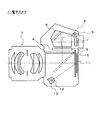
電子カメラ1は、一眼レフレックスタイプの電子カメラであり、撮影レンズ3、ミラー4、スクリーン5、ペンタプリズム6、接眼レンズ7、集光レンズ8、測光素子9を備える。なお、撮影レンズ3は本体から着脱可能であっても良い。
Hereinafter, embodiments of the present invention will be described with reference to the drawings. In the present embodiment, description will be made using an electronic camera equipped with the photometric device of the present invention.
The electronic camera 1 is a single-lens reflex type electronic camera, and includes a photographing lens 3, a mirror 4, a
ミラー4が実線で示したミラーアップ状態となることにより、撮影が可能となる。また、ミラー4が破線で示したミラーダウン状態となることにより、撮影が不可となると共にユーザによる被写体の目視が可能となる。
非撮影時に、撮影レンズ3を透過した光束は、ミラーダウン状態のミラー4にて反射され、スクリーン5、ペンタプリズム6を介して接眼レンズ7に導かれる。
Shooting is possible when the mirror 4 is in the mirror-up state indicated by the solid line. Further, when the mirror 4 is in a mirror-down state indicated by a broken line, shooting is not possible and the user can visually observe the subject.
At the time of non-photographing, the light beam transmitted through the photographing lens 3 is reflected by the mirror 4 in the mirror-down state, and is guided to the
なお、非撮影時に、ミラー4で反射した光束の一部の光は、スクリーン5、ペンタプリズム6、集光レンズ8を介して測光素子9に導かれる。測光素子9の出力は、露出時間の算出やホワイトバランス係数の算出に用いられる(詳細は後述する)。
また、電子カメラ1は、図1に示すように、シャッタ10、CCD撮像素子11、集光レンズ12、調光用素子13を備える。
Note that, at the time of non-photographing, part of the light beam reflected by the mirror 4 is guided to the photometric element 9 via the
Further, as shown in FIG. 1, the electronic camera 1 includes a
撮影時には、撮影レンズ3内の不図示の絞りが絞り込まれた後、シャッタ10の幕開マグネット(不図示)のOFFによりCCD撮像素子11による撮像が開始される。このとき、ミラー4はミラーアップ状態となっており、撮影レンズ3を通過した被写体光は、CCD撮像素子11上に結像される。そして、シャッタ10の幕閉マグネット(不図示)のOFFにより撮像が終了する。
At the time of shooting, after an aperture (not shown) in the taking lens 3 is narrowed down, imaging by the
さらに、不図示の閃光部による本発光中に、CCD撮像素子11上に結像された光の一部はCCD撮像素子11上で反射され、集光レンズ12を介して調光用素子13上に結像される。この調光用素子13による測光は、この本発光中に継続して行われ、測光の結果に基づいて閃光部の制御が行われる。
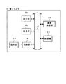
図2は、電子カメラ1の機能ブロック図である。電子カメラ1は、制御部14、測光部15、撮像部16、画像処理部17、記録部18を備え、これらの各部はバスを介して相互に接続される。また、電子カメラ1は、不図示の電源ボタンやレリーズボタンなどを含む操作部19を備える。
Further, during the main light emission by a flash unit (not shown), a part of the light imaged on the CCD
FIG. 2 is a functional block diagram of the electronic camera 1. The electronic camera 1 includes a
制御部14は、CPUや各部を制御するためのプログラムを予め記録している。また、制御部14は、本発明の特徴である測光および測色情報の算出も行う(詳細は後述する)。測光部15は、図1で説明した測光素子9を含み、被写界を測光する。撮像部16は、図1で説明した撮影レンズ3、シャッタ10、CCD撮像素子11を含み、被写体像を撮像して画像を生成する。
The
また、画像処理部17は、撮像部16により生成された画像に対してホワイトバランス調整などの所定の画像処理を施す。また、記録部18は、画像処理部17により画像処理が施された画像を記録し、メモリカードなどのリムーバブルメモリを着脱可能である。
なお、測光部15および制御部14は、請求項1から請求項6の「測光部」に対応し、制御部14は、請求項1の「取得部」に対応する。
Further, the
The
また、測光部15および制御部14は、請求項7から請求項12の「測色センサ」および「フィルタ群」に対応し、制御部14は、請求項7の「測光部」および「測色部」に対応する。
次に、本発明の特徴である測光部15と測光および測色情報の算出とについて詳細に説明する。
The
Next, the
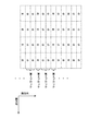
図3は、測光素子9の測光面の一部を拡大した図である。測光素子9は、図3に示すように、Gで示す緑色センサ(以下、「Gセンサ」と称する)と、Rで示す赤色センサ(以下、「Rセンサ」と称する)と、Bで示す青色センサ(「Bセンサ」と称する)とを有し、各センサは測光面にマトリクス状に配列される。そして、Gセンサが縦方向に沿って2列に配列された第1のブロックと、RセンサとBセンサとが縦方向に沿って交互に繰り返し配列された第2のブロックと、第1のブロックと同一の配列の第3のブロックと、第2のブロックにおけるRセンサとBセンサとが入れ替わった配列の第4のブロックとが、横方向に沿って順次繰り返し配列される。このような配列により、Gセンサの単位面積比が、他の色のセンサの単位面積比よりも大きくなる。 FIG. 3 is an enlarged view of a part of the photometric surface of the photometric element 9. As shown in FIG. 3, the photometric element 9 includes a green sensor indicated by G (hereinafter referred to as “G sensor”), a red sensor indicated by R (hereinafter referred to as “R sensor”), and a blue color indicated by B. Sensors (referred to as “B sensors”), and each sensor is arranged in a matrix on the photometric surface. A first block in which G sensors are arranged in two rows along the vertical direction, a second block in which R sensors and B sensors are alternately arranged in the vertical direction, and a first block And a fourth block in which the R sensor and the B sensor in the second block are interchanged are sequentially and repeatedly arranged in the horizontal direction. With such an arrangement, the unit area ratio of the G sensor is larger than the unit area ratios of the sensors of other colors.
なお、緑色センサは、請求項1および請求項2の「第1の測光センサ」に対応し、赤色センサは、請求項1の「第2の測光センサ」に対応し、青色センサは、請求項1の「第3の測光センサ」に対応する。また、縦方向は、請求項1および請求項7の「第1の方向」に対応し、横方向は、請求項1および請求項7の「第2の方向」に対応する。
各測光センサは、測光面に、透過する光の波長が異なるフィルタを備えている。Gセンサは、緑色フィルタを備え、Rセンサは、赤色フィルタを備え、Bセンサは、青色フィルタを備える。図4は、各フィルタの分光透過係数を示すグラフである。
The green sensor corresponds to the “first photometric sensor” in claims 1 and 2, the red sensor corresponds to the “second photometric sensor” in claim 1, and the blue sensor corresponds to the claim. 1 corresponding to “third photometric sensor”. The vertical direction corresponds to the “first direction” in
Each photometric sensor includes filters having different wavelengths of light to be transmitted on the photometric surface. The G sensor includes a green filter, the R sensor includes a red filter, and the B sensor includes a blue filter. FIG. 4 is a graph showing the spectral transmission coefficient of each filter.
なお、緑色フィルタは、請求項7および請求項8の「第1のフィルタ」に対応し、赤色フィルタは、請求項7の「第2のフィルタ」に対応し、青色フィルタは、請求項7の「第3のフィルタ」に対応する。
測光部15は、非撮影時に、撮影レンズ3を透過した光束を測光素子9の各測光センサを介して受光し、それぞれの測光センサで光電変換を行って得た電荷を電圧変換する。そして、測光部15は、電圧変換後の信号を増幅し、A/D変換によりディジタル信号に変換して、測光値として制御部14に出力する。このとき、Rセンサにより得られる測光値を「R」、Gセンサにより得られる測光値を「G」、Bセンサにより得られる測光値を「B」とする。
The green filter corresponds to the “first filter” in
When not photographing, the
制御部14は、まず、測光部15により得られた測光値(R,G,B)の平均値を測光領域ごとに求める。なお、測光領域は、スポット測光、中央重点測光などの測光の形態に応じて予め定められているものとする。また、測光値(R,G,B)の平均値をそれぞれRm,Gm,Bmと称する。
制御部14は、この平均値(Rm,Gm,Bm)に基づき、以下の各式1〜4を用いて、測光領域ごとにRGB各色のホワイトバランス係数(Rw,Gw,Bw)および輝度値(Y)を求める。
Rw=aRm・・・(式1)
Bw=bBm・・・(式2)
Gw=cGm・・・(式3)
Y=dRm+eGm+fBm・・・(式4)
なお、式1から式4におけるaからfは、測光センサに備えられたフィルタの分光透過係数に応じて決まる比例定数である。
First, the
Based on this average value (Rm, Gm, Bm), the
Rw = aRm (Formula 1)
Bw = bBm (Formula 2)
Gw = cGm (Formula 3)
Y = dRm + eGm + fBm (Formula 4)
Note that a to f in Equations 1 to 4 are proportional constants determined according to the spectral transmission coefficient of the filter provided in the photometric sensor.
なお、人の視感度は、Gフィルタと略同じ550nm近傍にピークを持つ。Gフィルタの視感度を1としたときのRフィルタ(650nmピーク)の比視感度は約0.11であり、Bフィルタ(450nmピーク)の比視感度は、約0.04である。つまり、前述した式4において、eGmは、dRmおよびfBmよりも充分に大きい値である。そのため、輝度値(Y)については、Gセンサに寄与が最も大きいことになり、式4を以下の近似式に置き換えることができる。
Y=e’Gm・・・(式5)
この式5は、被写体が極端に純度の高い青色や赤色である場合を除いて、有効である。
The human visibility has a peak in the vicinity of 550 nm, which is substantially the same as that of the G filter. The relative visibility of the R filter (650 nm peak) when the visibility of the G filter is 1 is about 0.11, and the relative visibility of the B filter (450 nm peak) is about 0.04. That is, in the above-described Expression 4, eGm is a value sufficiently larger than dRm and fBm. Therefore, the luminance value (Y) has the largest contribution to the G sensor, and Equation 4 can be replaced with the following approximate equation.
Y = e′Gm (Formula 5)
制御部14は、このようにして算出したホワイトバランス係数(Rw,Gw,Bw)および輝度値(Y)をもとに、ホワイトバランス調整や自動露光に関わる条件を設定する。
なお、ホワイトバランス係数(Rw,Gw,Bw)は請求項の「測色情報」に対応し、輝度値(Y)は請求項の「測光情報」に対応する。
ここまで説明したように、測光素子9におけるGセンサの単位面積比が、他の色センサの単位面積比よりも大きくなるように測光センサを配列することにより、式5により求められる輝度値(Y)の感度が増感する。輝度値(Y)は測光感度と比例関係にあるため、前述した配列により、測光感度を増感させることができる。
Based on the white balance coefficients (Rw, Gw, Bw) and luminance values (Y) calculated in this way, the
The white balance coefficient (Rw, Gw, Bw) corresponds to “colorimetric information” in claims, and the luminance value (Y) corresponds to “photometric information” in claims.
As described so far, by arranging the photometric sensors so that the unit area ratio of the G sensor in the photometric element 9 is larger than the unit area ratios of the other color sensors, the luminance value (Y ) Sensitivity is increased. Since the luminance value (Y) is proportional to the photometric sensitivity, the photometric sensitivity can be enhanced by the arrangement described above.
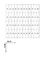
ここで、本発明によって、測光感度をどの程度増感できるかを考察する。以下では、従来より用いられている測光素子の配列として、図5に示すストライプ配列を用いて比較を行う。ストライプ配列は、図5に示すように、Rセンサ、Gセンサ、Bセンサが測光素子の縦方向に1列ずつ配置され、その3列が横方向に繰り返し配列された配列である。
このストライプ配列において、各色の測光センサの比は、以下の式6のようになる。
R:G:B=1:1:1・・・(式6)
一方、本発明の測光素子9の配列において、各色の測光センサの比は、以下の式7のようになる。
R:G:B=1:4:1・・・(式7)
したがって、本発明の測光素子9のGセンサの単位面積比は、ストライプ配列の場合の2倍になる。
Here, how much the photometric sensitivity can be enhanced by the present invention will be considered. In the following, a comparison is made using the stripe arrangement shown in FIG. 5 as the arrangement of photometric elements conventionally used. As shown in FIG. 5, the stripe arrangement is an arrangement in which the R sensor, the G sensor, and the B sensor are arranged one by one in the vertical direction of the photometric element, and the three rows are repeatedly arranged in the horizontal direction.
In this stripe arrangement, the ratio of the photometric sensors for the respective colors is as shown in Equation 6 below.
R: G: B = 1: 1: 1 (Formula 6)
On the other hand, in the arrangement of the photometric elements 9 of the present invention, the ratio of the photometric sensors of the respective colors is expressed by the following
R: G: B = 1: 4: 1 (Formula 7)
Therefore, the unit area ratio of the G sensor of the photometric element 9 of the present invention is twice that of the stripe arrangement.
正規分布を仮定すれば、サンプル数nのとき、標準偏差は以下の式8で求められる。
標準偏差=1÷√n・・・(式8)
単位面積比は2倍であるので、Gセンサによる誤差(標準偏差)は以下の式9で求められる。
Gセンサによる誤差(標準偏差)=1÷√2=1÷1.41・・・(式9)
光量0のとき、Gセンサの出力が誤差と等しいので、検出限界は誤差で決まる。したがって、誤差が減少したぶんだけ検出限界が向上し、約41%の増感となる。
Assuming a normal distribution, when the number of samples is n, the standard deviation is obtained by the following equation (8).
Standard deviation = 1 ÷ √n (Equation 8)
Since the unit area ratio is twice, the error (standard deviation) by the G sensor is obtained by the following equation (9).
Error (standard deviation) by G sensor = 1 ÷ √2 = 1 ÷ 1.41 (Equation 9)
Since the output of the G sensor is equal to the error when the light quantity is 0, the detection limit is determined by the error. Therefore, the detection limit is improved as much as the error is reduced, and the sensitization is about 41%.
以上説明したように、本実施形態によれば、Gセンサの単位面積比を大きくすることにより、測光感度を増感させることができる。したがって、測光面を大きくすることなく、小型でありながら感度の高い測光および測色を行うことができる。
なお、Gセンサの単位面積比を大きくすることにより、RセンサおよびBセンサの単位面積比は小さくなる。しかし、電子カメラではホワイトバランス調整に関わる正確な測光情報は、情報量の多い撮像用の画素データを用いた方が有利である。そのため、測光センサに要求されるのは、画像取得前の粗計測である。したがって、RセンサおよびBセンサの単位面積比が多少小さくなっても充分な測色情報を得ることができる。
As described above, according to the present embodiment, the photometric sensitivity can be increased by increasing the unit area ratio of the G sensor. Therefore, it is possible to perform photometry and colorimetry with high sensitivity while being small without increasing the photometric surface.
Note that the unit area ratio of the R sensor and the B sensor is reduced by increasing the unit area ratio of the G sensor. However, in the electronic camera, it is more advantageous to use imaging pixel data with a large amount of information for accurate photometric information related to white balance adjustment. Therefore, what is required of the photometric sensor is rough measurement before image acquisition. Therefore, sufficient colorimetric information can be obtained even if the unit area ratio of the R sensor and the B sensor is somewhat reduced.
なお、本実施形態では、測光素子9の配列において、Gセンサを2列に配列する例を示した(図3参照)が、3列以上にしても良い。Gセンサの列を増やすことにより、測光感度は増感し、測色感度は低下する。したがって、要求する測光および測色感度のバランスに応じて、Gセンサの列数を決めると良い。また分割測光において、測光領域内に含まれるRセンサおよびBセンサの数も考慮して決めると良い。 In this embodiment, the example in which the G sensors are arranged in two rows in the arrangement of the photometric elements 9 (see FIG. 3) may be three or more. By increasing the number of G sensors, the photometric sensitivity is increased and the colorimetric sensitivity is decreased. Therefore, it is preferable to determine the number of columns of the G sensor according to the required balance between photometry and colorimetry sensitivity. In the divided photometry, the number of R sensors and B sensors included in the photometry area may be determined in consideration.
また、本実施形態では、本発明の測光装置を備えた電子カメラ1を用いて説明を行ったが、銀塩カメラに本発明を適用しても良い。
〈変形例〉
上述した実施形態において、測光素子9のGセンサを、少なくとも550nm近傍の波長域に分光感度を有する以下のセンサの何れかに変更しても良い。
(1)比視感度フィルタを備えたセンサ
(2)黄色の補色フィルタを備えたセンサ
(3)全透過フィルタを備えたセンサ
比視感度フィルタおよび黄色の補色フィルタの分光透過係数を図4に示す。また、Gフィルタの透過係数を1とすると、比視感度フィルタの透過係数は約2であり、黄色の補色フィルタの透過係数は約3であり、全透過フィルタの透過係数は約4である。
In this embodiment, the electronic camera 1 provided with the photometric device according to the present invention has been described. However, the present invention may be applied to a silver salt camera.
<Modification>
In the above-described embodiment, the G sensor of the photometric element 9 may be changed to any of the following sensors having spectral sensitivity in a wavelength region near at least 550 nm.
(1) Sensor with specific luminous efficiency filter (2) Sensor with yellow complementary color filter (3) Sensor with full transmission filter Spectral transmission coefficients of the specific luminous efficiency filter and the yellow complementary color filter are shown in FIG. . If the transmission coefficient of the G filter is 1, the transmission coefficient of the relative luminous efficiency filter is about 2, the transmission coefficient of the yellow complementary color filter is about 3, and the transmission coefficient of the total transmission filter is about 4.
したがって、Gセンサを上記の各センサに変更することにより、測光感度をさらに増感することができる。
特に、比視感度フィルタを備えたセンサの何れかに変更する場合、被写体がさらに暗い場合にも測光感度を確保できる。この場合、測色感度は多少低下するが、被写体が赤や青の原色に近い場合には充分な効果を得ることができる。
Therefore, the photometric sensitivity can be further enhanced by changing the G sensor to each of the above sensors.
In particular, when the sensor is changed to any one provided with a relative luminous efficiency filter, the photometric sensitivity can be ensured even when the subject is darker. In this case, the colorimetric sensitivity is somewhat lowered, but a sufficient effect can be obtained when the subject is close to the primary colors of red and blue.
また、黄色の補色フィルタを備えたセンサに変更する場合、特別なレジストを用意する必要がないので、製造上のメリットが大きい。
なお、上記各センサに変更した場合、上述した式3を、以下の式10に変更し、式4を以下の式11に変更すれば良い。なお、以下の各式において、Xmは、Gセンサの代わりに用いられたセンサによる測光値の、測光領域内の平均値を表す。
Gw=gXm−hRm−iBm・・・(式10)
Y=jXm・・・(式11)
ただし、式10および式11におけるgからjは、測光センサに備えられたフィルタの分光特性に応じて決まる比例定数である。
Further, when changing to a sensor having a yellow complementary color filter, it is not necessary to prepare a special resist, so that there is a great merit in manufacturing.
In addition, when it changes to said each sensor, what is necessary is just to change the formula 3 mentioned above into the following
Gw = gXm−hRm−iBm (Formula 10)
Y = jXm (Formula 11)
However, g to j in
このように、測光素子9のGセンサをほかのセンサに変更することにより、Gのホワイトバランス係数(Gw)について演算が必要になるため、測色感度は多少低下するが、フィルタの透過率が高いため、測色感度をさらに増感することができる。
実施形態および上述したセンサの変更によって、測光感度が増感することを説明した。その結果、このような測光感度の増感により低輝度検出限界が向上する。しかし、その一方で、高輝度検出限界は悪化する。高輝度検出限界の悪化は、通常の測光では問題になるレベルではない。しかしながら、近年はストロボ撮影時の予備発光時測光の際にも測光素子9による測光の結果が用いられている。一般に、ストロボ撮影時においては小発光の制御が難しく、正確に発光させるためにはある程度の光量が必要である。さらに、ストロボ撮影時において、近距離撮影、明るいレンズ、高反射被写体などの条件が重なると高輝度検出限界に達する場合が考えられる。このような場合には、前述した高輝度検出限界の悪化が問題となる場合がある。
In this way, by changing the G sensor of the photometric element 9 to another sensor, it is necessary to calculate the white balance coefficient (Gw) of G, so that the colorimetric sensitivity is somewhat lowered, but the transmittance of the filter is low. Since it is high, the colorimetric sensitivity can be further enhanced.
It has been described that the photometric sensitivity is enhanced by the change in the embodiment and the sensor described above. As a result, the low luminance detection limit is improved by such enhancement of photometric sensitivity. However, on the other hand, the high brightness detection limit deteriorates. The deterioration of the high-luminance detection limit is not at a level that causes a problem in normal photometry. However, in recent years, the result of photometry by the photometry element 9 is also used for pre-flash photometry during flash photography. In general, it is difficult to control small light emission at the time of flash photography, and a certain amount of light is required for accurate light emission. Furthermore, in the flash photography, if conditions such as short-distance photography, a bright lens, and a highly reflective subject overlap, the high brightness detection limit may be reached. In such a case, the deterioration of the high luminance detection limit described above may be a problem.
上述した問題を回避するために、測光素子9のGセンサ(または比視感度フィルタを備えたセンサ、または黄色の補色フィルタを備えたセンサ、または全透過フィルタを備えたセンサ)の一部を、より透過率の低いセンサに変更しても良い。
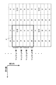
図6は、測光素子9の測光面の一部を拡大した図であり、図3に示した測光素子9の一部を、NDセンサに変更した場合の例を示す。NDセンサは、NDフィルタ(neutral density filter)を備えたセンサであり、透過率の低いセンサの一例である。このような透過率の低いセンサは、請求項6の「第4の測光センサ」に対応し、透過率の低いセンサが備えるフィルタは、請求項12の「第4のフィルタ」に対応する。図6では、枠kで囲んだ縦2列、横6列を1つのパターンとし、各パターンにおいて1カ所ずつ、Gセンサに換えてNDセンサを備える例を示している。
In order to avoid the problems described above, a part of the G sensor (or a sensor with a relative luminous efficiency filter, a sensor with a yellow complementary color filter, or a sensor with an all-transmissive filter) of the photometric element 9 is It may be changed to a sensor with lower transmittance.
FIG. 6 is an enlarged view of a part of the photometric surface of the photometric element 9, and shows an example in which a part of the photometric element 9 shown in FIG. 3 is changed to an ND sensor. The ND sensor is a sensor including an ND filter (neutral density filter), and is an example of a sensor having low transmittance. Such a low-transmittance sensor corresponds to the “fourth photometric sensor” in claim 6, and the filter included in the low-transmittance sensor corresponds to the “fourth filter” in
ここで、図6に示す測光素子9の配列について考察する。
図6に示す測光素子9の配列において、各色の測光センサの比は、以下の式12のようになる。
R:G:B:ND=2:7:2:1・・・(式12)
ストライプ配列における各色の測光センサの比は、式6に示すように、R:G:B=1:1:1であり、上述した縦2列、横6列のパターンにおいては、R:G:B=4:4:4である。したがって、ストライプ配列の場合を基準としたG画素の単位面積比は、以下の式13のようになる。
7÷4=1.75・・・(式13)
単位面積比は1.75倍であるので、Gセンサによる誤差(標準偏差)は以下の式14で求められる。
Gセンサによる誤差(標準偏差)=1÷√1.75=1÷1.32・・・(式14)
上述したように、光量0のとき、Gセンサの出力が誤差と等しいので、検出限界は誤差で決まる。したがって、約32%の増感となる。
Here, the arrangement of the photometric elements 9 shown in FIG. 6 will be considered.
In the arrangement of the photometric elements 9 shown in FIG. 6, the ratio of the photometric sensors of the respective colors is expressed by the following
R: G: B: ND = 2: 7: 2: 1 (Formula 12)
The ratio of the photometric sensors for each color in the stripe arrangement is R: G: B = 1: 1: 1 as shown in Equation 6, and in the pattern of 2 rows and 6 rows described above, R: G: B = 4: 4: 4. Therefore, the unit area ratio of the G pixel based on the case of the stripe arrangement is expressed by
7 ÷ 4 = 1.75 (Equation 13)
Since the unit area ratio is 1.75 times, the error (standard deviation) by the G sensor is obtained by the following equation (14).
Error (standard deviation) by G sensor = 1 ÷ √1.75 = 1 ÷ 1.32 (Equation 14)
As described above, when the amount of light is 0, the output of the G sensor is equal to the error, so the detection limit is determined by the error. Therefore, the sensitization is about 32%.
式9に示したように、図3に示す測光素子9の配列での増感は41%であったため、NDセンサを配列に組み込むことにより、増感の度合いは減る。しかし、上述したように、比視感度フィルタ等の透過係数の大きいフィルタを備えたセンサを使用すれば、充分な増感が得られる。そして、ストロボ撮影時において、近距離撮影、明るいレンズ、高反射被写体などの条件が重なり、検出限界に達した場合でも、NDセンサによる測光の結果を参照することにより、被写体の輝度を測光できる。 As shown in Equation 9, since the sensitization in the arrangement of the photometric elements 9 shown in FIG. 3 was 41%, the degree of sensitization is reduced by incorporating the ND sensor into the arrangement. However, as described above, sufficient sensitization can be obtained by using a sensor provided with a filter having a large transmission coefficient such as a relative visibility filter. In the flash photography, even when conditions such as short-distance photography, a bright lens, and a highly reflective subject overlap and reach the detection limit, the luminance of the subject can be measured by referring to the result of photometry by the ND sensor.
なお、NDフィルタの透過率を10%、Gフィルタの透過率を25%と仮定すると、Gフィルタの透過係数を1として、高輝度検出限界は2.5になる。また、Gフィルタの透過係数を1とすると、前述したように、比視感度フィルタの透過係数は約2であり、黄色の補色フィルタの透過係数は約3であり、全透過フィルタの透過係数は約4である。そのため、図6に示す測光素子9の配列において、Gセンサに換えて比視感度フィルタを備えたセンサ、黄色の補色フィルタを備えたセンサ、全透過フィルタを備えたセンサを使用した場合の低輝度検出限界は、それぞれ、Gセンサの場合は約1.3、比視感度フィルタを備えたセンサの場合は1.3×2=約2.6、黄色の補色フィルタを備えたセンサの場合1.3×3=約3.9倍、全透過フィルタを備えたセンサの場合1.3×4=約5.2になる。 Assuming that the transmittance of the ND filter is 10% and the transmittance of the G filter is 25%, the transmission coefficient of the G filter is 1, and the high luminance detection limit is 2.5. If the transmission coefficient of the G filter is 1, as described above, the transmission coefficient of the relative luminous efficiency filter is about 2, the transmission coefficient of the yellow complementary color filter is about 3, and the transmission coefficient of the total transmission filter is About 4. Therefore, in the arrangement of the photometric elements 9 shown in FIG. 6, low luminance when using a sensor with a relative visibility filter instead of a G sensor, a sensor with a yellow complementary color filter, and a sensor with an all-transmissive filter is used. The detection limits are about 1.3 for the G sensor, 1.3 × 2 = about 2.6 for the sensor with the relative visibility filter, and 1. for the sensor with the yellow complementary color filter. 3 × 3 = about 3.9 times, and in the case of a sensor having a total transmission filter, 1.3 × 4 = about 5.2.
なお、透過率の低いセンサの一例として、NDセンサを挙げたが、透過率の低いセンサとして、緑色フィルタよりも透過率の低いフィルタを備えたセンサや、比視感度フィルタよりも透過率の低いフィルタを備えたセンサなどを使用しても良い。
また、図6では、各パターンにおいて1カ所ずつ、Gセンサに換えて透過率の低いセンサを備える例を示したが、透過率の低いセンサの数や配置はこの例に限定されない。透過率の低いセンサの数については、そのセンサの透過率や、必要とする低輝度時検出限界などに応じて決めるのが好ましい。また、配置については、測光領域ごとに1カ所程度含まれるように配置するのが好ましい。
Although an ND sensor has been described as an example of a sensor having a low transmittance, a sensor having a filter having a transmittance lower than that of a green filter or a transmittance having a transmittance lower than that of a relative luminous efficiency filter is used as a sensor having a low transmittance. A sensor provided with a filter may be used.
Further, FIG. 6 shows an example in which a low transmittance sensor is provided instead of the G sensor at one place in each pattern, but the number and arrangement of the low transmittance sensors are not limited to this example. The number of sensors with low transmittance is preferably determined according to the transmittance of the sensor, the required detection limit at low luminance, and the like. Further, the arrangement is preferably arranged so that about one place is included in each photometric area.
以上説明したように、Gセンサに換えて、Gセンサよりも透過率の低いセンサ(NDセンサなど)を一部に備えることにより、低輝度検出限界が向上させつつ、ストロボ予備発光時の測光の際に必要となる高輝度検出限界も確保することができる。 As described above, instead of the G sensor, a sensor (such as an ND sensor) having a transmittance lower than that of the G sensor is provided in part, so that the low luminance detection limit is improved and the photometry during the strobe preliminary light emission is improved. The high-luminance detection limit required at the time can also be secured.
1 電子カメラ
3 撮影レンズ
4 ミラー
5 スクリーン
6 ペンタプリズム
7 接眼レンズ
8,12 集光レンズ
9 測光素子
10 シャッタ
11 CCD撮像素子
13 調光用素子
14 制御部
15 測光部
16 撮像部
17 画像処理部
18 記録部
19 操作部
DESCRIPTION OF SYMBOLS 1 Electronic camera 3 Shooting lens 4
Claims (13)
前記測光部により出力された前記複数の測光値に応じて測色情報と測光情報とを取得する取得部と
を備えたことを特徴とする測光装置。 A first photometric sensor having a spectral sensitivity in a wavelength region of at least 550 nm, a second photometric sensor having a spectral sensitivity peak in a red wavelength region, and a third photometric sensor having a spectral sensitivity peak in a blue wavelength region. Each photometric sensor is arranged in a matrix on the photometric surface, and the first photometric sensor is arranged in at least two rows along a first direction of the photometric surface; and A second block in which the second photometric sensor and the third photometric sensor are alternately and repeatedly arranged along the first direction; and a third block having the same arrangement as the first block; A fourth block in which the second photometric sensor and the third photometric sensor in the second block are interchanged is sequentially and repeatedly arranged along a second direction orthogonal to the first direction. Been Ri, a photometry unit for outputting a plurality of photometric values obtained by each of the photometric sensor,
A photometric device comprising: an acquisition unit that acquires colorimetric information and photometric information according to the plurality of photometric values output by the photometric unit.
前記測光部は、前記第1の測光センサとして緑色フィルタを備えた受光部を用いる
ことを特徴とする測光装置。 The photometric device according to claim 1,
The photometric unit uses a light receiving unit having a green filter as the first photometric sensor.
前記測光部は、前記第1の測光センサとして比視感度フィルタを備えた受光部を用いる
ことを特徴とする測光装置。 The photometric device according to claim 1,
The photometric unit uses a light receiving unit including a relative visibility filter as the first photometric sensor.
前記測光部は、前記第1の測光センサとして黄色の補色フィルタを備えた受光部を用いる
ことを特徴とする測光装置。 The photometric device according to claim 1,
The photometric unit uses a light receiving unit including a yellow complementary color filter as the first photometric sensor.
前記測光部は、前記第1の測光センサとして全透過フィルタを備えた受光部を用いる
ことを特徴とする測光装置。 The photometric device according to claim 1,
The photometric unit uses a light receiving unit including a total transmission filter as the first photometric sensor.
前記測光部は、前記第1の測光センサよりも透過率の低い第4の測光センサを有し、前記第1のブロックと前記第3のブロックとの少なくとも一方の一部に、前記第1の測光センサに換えて前記第4の測光センサを備える
ことを特徴とする測光装置。 The photometric device according to claim 1,
The photometric unit includes a fourth photometric sensor having a transmittance lower than that of the first photometric sensor, and the first photometric unit includes at least a part of at least one of the first block and the third block. A photometric device comprising the fourth photometric sensor instead of the photometric sensor.
少なくとも550nm近傍の波長域の光を透過する第1のフィルタと、赤色波長域の光を透過する第2のフィルタと、青色波長域の光を透過する第3のフィルタとを有し、かつ、前記第1のフィルタが前記マトリクス上に配列された前記複数の受光素子の第1の方向に沿って少なくとも2列に配列された第1のブロックと、前記第2のフィルタと前記第3のフィルタとが前記第1の方向に沿って交互に繰り返し配列された第2のブロックと、前記第1のブロックと同一の配列の第3のブロックと、前記第2のブロックにおける前記第2のフィルタと前記第3のフィルタとが入れ替わった配列の第4のブロックとが、前記第1の方向に直交する第2の方向に沿って順次繰り返し配列されて成るフィルタ群と、
前記フィルタ群を介して、前記測光センサの前記受光素子により検出された前記光量に基づいて測光情報を検出する測光部と、
前記測光部により検出された前記測光情報に基づいて測色情報を検出する測色部と
を備えたことを特徴とする測光装置。 A plurality of light receiving elements arranged in a matrix, a photometric sensor for detecting the amount of light received by the plurality of light receiving elements;
A first filter that transmits light in a wavelength region near at least 550 nm, a second filter that transmits light in a red wavelength region, and a third filter that transmits light in a blue wavelength region, and A first block in which the first filter is arranged in at least two columns along a first direction of the plurality of light receiving elements arranged on the matrix; the second filter; and the third filter. Are alternately and repeatedly arranged along the first direction, a third block having the same arrangement as the first block, and the second filter in the second block; A filter group in which a fourth block in an array in which the third filter is replaced is sequentially and repeatedly arranged along a second direction orthogonal to the first direction;
A photometric unit that detects photometric information based on the amount of light detected by the light receiving element of the photometric sensor via the filter group;
A photometric device comprising: a colorimetric unit that detects colorimetric information based on the photometric information detected by the photometric unit.
前記フィルタ群は、前記第1のフィルタとして緑色フィルタを備える
ことを特徴とする測光装置。 The photometric device according to claim 7,
The filter group includes a green filter as the first filter.
前記フィルタ群は、前記第1のフィルタとして比視感度フィルタを備える
ことを特徴とする測光装置。 The photometric device according to claim 7,
The photometric device, wherein the filter group includes a relative visibility filter as the first filter.
前記フィルタ群は、前記第1のフィルタとして黄色の補色フィルタを備える
ことを特徴とする測光装置。 The photometric device according to claim 7,
The photometric apparatus, wherein the filter group includes a yellow complementary color filter as the first filter.
前記フィルタ群は、前記第1のフィルタとして全透過フィルタを備える
ことを特徴とする測光装置。 The photometric device according to claim 7,
The filter group includes a total transmission filter as the first filter.
前記フィルタ群は、前記第1のフィルタよりも透過率の低い第4のフィルタを有し、前記第1のブロックと前記第3のブロックとの少なくとも一方の一部に、前記第1のフィルタに換えて前記第4のフィルタを備える
ことを特徴とする測光装置。 The photometric device according to claim 7,
The filter group includes a fourth filter having a transmittance lower than that of the first filter, and at least part of at least one of the first block and the third block is included in the first filter. A photometric device comprising the fourth filter instead.
ことを特徴とするカメラ。
A camera comprising the photometric device according to any one of claims 1 to 12.
Priority Applications (1)
| Application Number | Priority Date | Filing Date | Title |
|---|---|---|---|
| JP2005004244A JP2005292784A (en) | 2004-03-09 | 2005-01-11 | Photometric device equipped with color measuring function and camera equipped with photometric device |
Applications Claiming Priority (2)
| Application Number | Priority Date | Filing Date | Title |
|---|---|---|---|
| JP2004066062 | 2004-03-09 | ||
| JP2005004244A JP2005292784A (en) | 2004-03-09 | 2005-01-11 | Photometric device equipped with color measuring function and camera equipped with photometric device |
Publications (2)
| Publication Number | Publication Date |
|---|---|
| JP2005292784A true JP2005292784A (en) | 2005-10-20 |
| JP2005292784A5 JP2005292784A5 (en) | 2008-02-28 |
Family
ID=35325720
Family Applications (1)
| Application Number | Title | Priority Date | Filing Date |
|---|---|---|---|
| JP2005004244A Pending JP2005292784A (en) | 2004-03-09 | 2005-01-11 | Photometric device equipped with color measuring function and camera equipped with photometric device |
Country Status (1)
| Country | Link |
|---|---|
| JP (1) | JP2005292784A (en) |
Cited By (5)
| Publication number | Priority date | Publication date | Assignee | Title |
|---|---|---|---|---|
| JP2008206014A (en) * | 2007-02-22 | 2008-09-04 | Nikon Corp | Photometric apparatus and imaging apparatus |
| JP2009532666A (en) * | 2006-04-01 | 2009-09-10 | カール ツアイス マイクロイメージング ゲゼルシャフト ミット ベシュレンクテル ハフツング | Spectroscopic measurement system and method for compensating false light |
| JP2009260411A (en) * | 2008-04-11 | 2009-11-05 | Olympus Corp | Image pickup apparatus |
| JP2013167682A (en) * | 2012-02-14 | 2013-08-29 | Nikon Corp | Photometric sensor and imaging apparatus |
| JP2015220686A (en) * | 2014-05-20 | 2015-12-07 | リコーイメージング株式会社 | Imaging apparatus and method for generating brightness information |
Citations (9)
| Publication number | Priority date | Publication date | Assignee | Title |
|---|---|---|---|---|
| JPH08220586A (en) * | 1995-02-13 | 1996-08-30 | Nikon Corp | Electronic camera |
| JPH09182091A (en) * | 1995-12-21 | 1997-07-11 | Sony Corp | Solid-state image pickup element, method for driving solid-state image pickup element, camera device and camera system |
| JPH10108079A (en) * | 1996-09-27 | 1998-04-24 | Toyota Central Res & Dev Lab Inc | Image-pickup device |
| JPH10313464A (en) * | 1996-12-30 | 1998-11-24 | Hyundai Electron Ind Co Ltd | Color filter array and its hue interpolating device |
| JP2001008240A (en) * | 1999-06-24 | 2001-01-12 | Minolta Co Ltd | Luminance characteristic measurement instrument for crt |
| JP2002084534A (en) * | 2000-09-08 | 2002-03-22 | Fujitsu Ten Ltd | Image processing device |
| JP2002142228A (en) * | 2000-10-31 | 2002-05-17 | Toyota Central Res & Dev Lab Inc | Image pickup device |
| JP2002303548A (en) * | 2000-12-08 | 2002-10-18 | Gretag Macbeth Ag | Device for photoelectric measurement of flat object to be measured |
| JP2003032694A (en) * | 2001-07-13 | 2003-01-31 | Fuji Photo Film Co Ltd | Solid-state imaging device and digital camera |
-
2005
- 2005-01-11 JP JP2005004244A patent/JP2005292784A/en active Pending
Patent Citations (9)
| Publication number | Priority date | Publication date | Assignee | Title |
|---|---|---|---|---|
| JPH08220586A (en) * | 1995-02-13 | 1996-08-30 | Nikon Corp | Electronic camera |
| JPH09182091A (en) * | 1995-12-21 | 1997-07-11 | Sony Corp | Solid-state image pickup element, method for driving solid-state image pickup element, camera device and camera system |
| JPH10108079A (en) * | 1996-09-27 | 1998-04-24 | Toyota Central Res & Dev Lab Inc | Image-pickup device |
| JPH10313464A (en) * | 1996-12-30 | 1998-11-24 | Hyundai Electron Ind Co Ltd | Color filter array and its hue interpolating device |
| JP2001008240A (en) * | 1999-06-24 | 2001-01-12 | Minolta Co Ltd | Luminance characteristic measurement instrument for crt |
| JP2002084534A (en) * | 2000-09-08 | 2002-03-22 | Fujitsu Ten Ltd | Image processing device |
| JP2002142228A (en) * | 2000-10-31 | 2002-05-17 | Toyota Central Res & Dev Lab Inc | Image pickup device |
| JP2002303548A (en) * | 2000-12-08 | 2002-10-18 | Gretag Macbeth Ag | Device for photoelectric measurement of flat object to be measured |
| JP2003032694A (en) * | 2001-07-13 | 2003-01-31 | Fuji Photo Film Co Ltd | Solid-state imaging device and digital camera |
Cited By (5)
| Publication number | Priority date | Publication date | Assignee | Title |
|---|---|---|---|---|
| JP2009532666A (en) * | 2006-04-01 | 2009-09-10 | カール ツアイス マイクロイメージング ゲゼルシャフト ミット ベシュレンクテル ハフツング | Spectroscopic measurement system and method for compensating false light |
| JP2008206014A (en) * | 2007-02-22 | 2008-09-04 | Nikon Corp | Photometric apparatus and imaging apparatus |
| JP2009260411A (en) * | 2008-04-11 | 2009-11-05 | Olympus Corp | Image pickup apparatus |
| JP2013167682A (en) * | 2012-02-14 | 2013-08-29 | Nikon Corp | Photometric sensor and imaging apparatus |
| JP2015220686A (en) * | 2014-05-20 | 2015-12-07 | リコーイメージング株式会社 | Imaging apparatus and method for generating brightness information |
Similar Documents
| Publication | Publication Date | Title |
|---|---|---|
| TWI462055B (en) | Cfa image with synthetic panchromatic image | |
| JP4020527B2 (en) | Electronic camera | |
| CN101843094B (en) | Picture pick-up device and control method thereof | |
| KR20090098197A (en) | Digital photographing apparatus to control flash lighting, controlling method for the same, and recording medium which records the program for carrying the same method | |
| CN108024056B (en) | Imaging method and device based on dual camera | |
| JP3436259B2 (en) | Photometric device | |
| JP2005292784A (en) | Photometric device equipped with color measuring function and camera equipped with photometric device | |
| JP6856762B2 (en) | Imaging device, information acquisition method and information acquisition program | |
| JP2015034850A (en) | Photographing device and photographing method | |
| JPH0784299A (en) | Photometry device for camera | |
| JP2004004449A (en) | Exposure control system for camera | |
| JP2011053377A (en) | Imaging apparatus and method for controlling the same | |
| JP6529214B2 (en) | Imaging device | |
| US20050030411A1 (en) | Digital still camera and image processing program | |
| JP4374121B2 (en) | Photometric device | |
| JP4884887B2 (en) | Imaging device | |
| JP5423140B2 (en) | Photometric device and imaging device | |
| JPH08242459A (en) | Light source information collectng device and image pickup device using the same | |
| JP2004215236A (en) | Image processing apparatus | |
| JP2006295774A (en) | Imaging apparatus, control method thereof, and image processing program for digital camera | |
| JP4413395B2 (en) | Photometric device | |
| JP4539254B2 (en) | Electronic camera and image processing program | |
| JP2005006217A (en) | Digital single lens reflex camera | |
| JP4586434B2 (en) | Flash control device and camera | |
| JP2010172013A (en) | Electronic camera, and image processing program |
Legal Events
| Date | Code | Title | Description |
|---|---|---|---|
| A621 | Written request for application examination |
Free format text: JAPANESE INTERMEDIATE CODE: A621 Effective date: 20071210 |
|
| A521 | Request for written amendment filed |
Free format text: JAPANESE INTERMEDIATE CODE: A523 Effective date: 20080115 |
|
| A131 | Notification of reasons for refusal |
Free format text: JAPANESE INTERMEDIATE CODE: A131 Effective date: 20090929 |
|
| A131 | Notification of reasons for refusal |
Free format text: JAPANESE INTERMEDIATE CODE: A131 Effective date: 20100223 |
|
| A521 | Request for written amendment filed |
Free format text: JAPANESE INTERMEDIATE CODE: A523 Effective date: 20100426 |
|
| A131 | Notification of reasons for refusal |
Free format text: JAPANESE INTERMEDIATE CODE: A131 Effective date: 20100810 |
|
| A521 | Request for written amendment filed |
Free format text: JAPANESE INTERMEDIATE CODE: A523 Effective date: 20101012 |
|
| A02 | Decision of refusal |
Free format text: JAPANESE INTERMEDIATE CODE: A02 Effective date: 20101207 |