JP2005292544A - Focusing mechanism - Google Patents
Focusing mechanism Download PDFInfo
- Publication number
- JP2005292544A JP2005292544A JP2004108856A JP2004108856A JP2005292544A JP 2005292544 A JP2005292544 A JP 2005292544A JP 2004108856 A JP2004108856 A JP 2004108856A JP 2004108856 A JP2004108856 A JP 2004108856A JP 2005292544 A JP2005292544 A JP 2005292544A
- Authority
- JP
- Japan
- Prior art keywords
- focus adjustment
- incident
- imaging device
- focus
- adjustment plate
- Prior art date
- Legal status (The legal status is an assumption and is not a legal conclusion. Google has not performed a legal analysis and makes no representation as to the accuracy of the status listed.)
- Pending
Links
Images
Abstract
Description
本発明は、例えば、デジタルカメラのレンズ群に組み込まれる遠近両用の焦点調整機構に関する。 The present invention relates to a far and near focus adjustment mechanism incorporated in a lens group of a digital camera, for example.
デジタルカメラ等で、画面の下半分に近くの人物を撮像し、上半分に背景となる遠方の景色を撮像する場合、いわゆるあおり補正により焦点を補正する技術がある。撮像装置を備えたカメラバックによりあおり補正を行う場合、従来では、通常、カメラボディとカメラバックの連結部にあおり機構を設けていた。 There is a technique for correcting the focus by so-called tilt correction when a digital camera or the like is used to image a person close to the lower half of the screen and an image of a distant landscape as a background in the upper half. When tilt correction is performed by a camera back equipped with an imaging device, conventionally, a tilt mechanism is usually provided at the connecting portion between the camera body and the camera back.
しかし、このような構成では、カメラが大型化するため、カメラバック内にあおり機構を設けるようにした提案が開示されている(例えば、特許文献1参照)。この場合、カメラボディに対して着脱自在なカメラバック内に撮像素子を内装した撮像装置を備え、前記撮像素子の中心が撮影光軸と一致した状態にて、撮像素子の撮像面を光軸に直交する軸を中心に傾動させる傾動機構を含むあおり機構を内装している。
ところで、近時は、ニーズの多様化に伴い、より一層簡易な構成であおり補正を実現できる斬新な発想が求められている。即ち、撮像素子をカメラボディ内に備えた一体型のデジタルカメラでもこのようなあおり補正を実現できることが望まれるようになった。しかし、このようなデジタルカメラには、スペースに制約があるため、上述の従来例のあおり機構をそのまま適用することはできない。 By the way, recently, with the diversification of needs, there has been a demand for a novel idea that can be corrected with a simpler configuration. That is, it has been desired that such tilt correction can be realized even with an integrated digital camera having an image sensor in the camera body. However, since the space is limited in such a digital camera, the above-described conventional tilt mechanism cannot be applied as it is.
本発明は、このような実情に鑑みてなされ、きわめて簡易な構成の遠近両用の焦点調整機構を提供することを目的とする。 The present invention has been made in view of such circumstances, and an object of the present invention is to provide a far and near focus adjustment mechanism having a very simple configuration.
本発明に係る焦点調整機構は、入射面と出射面とが所定の傾斜角度をなす傾斜部を少なくとも備え一枚の光学素材からなる焦点調整板を、レンズと撮像素子との間に配設し、前記焦点調整板の前記傾斜部において、薄肉部を透過した撮影光を近距離撮影光として前記撮像素子に入射させる一方、厚肉部を透過した撮影光を遠距離撮影光として前記撮像素子に入射させるようにしている。 In the focus adjustment mechanism according to the present invention, a focus adjustment plate made of a single optical material having at least an inclined portion in which an incident surface and an output surface form a predetermined inclination angle is disposed between a lens and an image sensor. In the inclined portion of the focus adjustment plate, the imaging light transmitted through the thin portion is incident on the imaging device as short-distance imaging light, while the imaging light transmitted through the thick portion is input to the imaging device as long-distance imaging light. It is made to enter.
このような構成によれば、レンズと撮像素子との間に配設した焦点調整板の薄肉部を透過した撮影光が近距離撮影光として撮像素子に入射され、厚肉部を透過した撮影光が遠距離撮影光として前記撮像素子に入射されるため、撮像画面の上半分では背景などの遠方の景色を鮮明に撮影し、下半分では近くの人物を鮮明に撮影することができ、遠近両方の焦点補正(あおり補正)が可能となる。 According to such a configuration, the photographing light transmitted through the thin portion of the focus adjustment plate disposed between the lens and the imaging device is incident on the imaging device as the short-distance photographing light, and the photographing light transmitted through the thick portion. Is incident on the image sensor as long-distance shooting light, so the upper half of the imaging screen can clearly shoot far-field scenery such as the background, and the lower half can shoot nearby people clearly, Focus correction (tilt correction) becomes possible.
また、好ましくは、前記焦点調整板は、前記入射面と前記出射面とを平行に形成した平行部をさらに備え、前記焦点調整板を移動させることにより前記傾斜部もしくは前記平行部のいずれか一方に撮影光を透過させるようにしてもよい。 Preferably, the focus adjustment plate further includes a parallel portion in which the incident surface and the emission surface are formed in parallel, and either the inclined portion or the parallel portion is moved by moving the focus adjustment plate. Alternatively, the photographing light may be transmitted.
このような構成によれば、焦点調整板の傾斜部に撮影光を透過させることにより、前記したようなあおり補正が可能になるとともに、焦点調整板の平行部に撮影光を透過させることにより、あおり補正を行わない撮影にも対応することができる。 According to such a configuration, by allowing the photographing light to pass through the inclined portion of the focus adjustment plate, it is possible to correct the tilt as described above, and by allowing the photographing light to pass through the parallel portion of the focus adjustment plate, It can also be used for shooting without tilt correction.
本発明に係る焦点調整機構は、入射面と出射面とが所定の傾斜角度をなし薄肉部から厚肉部へと肉厚が変化する一枚の光学素材からなる焦点調整板を、レンズと撮像素子との間に配設し、焦点調整板の薄肉部を透過した撮影光を近距離撮影光として撮像素子に入射させる一方、焦点調整板の厚肉部を透過した撮影光を遠距離撮影光として撮像素子に入射させるので、撮像画面の上半分では遠方の景色を鮮明に撮影し、下半分では近くの人物を鮮明に撮影することができる。 The focus adjustment mechanism according to the present invention includes a lens and an image of a focus adjustment plate made of a single optical material in which the incident surface and the output surface have a predetermined inclination angle and the thickness changes from the thin portion to the thick portion. The photographic light that is disposed between the sensor and the light passing through the thin part of the focus adjustment plate is incident on the image sensor as short-distance photography light, while the photographic light that is transmitted through the thick part of the focus adjustment plate is used as the long-distance photography light Therefore, the upper half of the imaging screen can clearly capture a distant view, and the lower half can clearly capture a nearby person.
以下に、本発明の最良の実施の形態に係る焦点調整機構について図面を参照しつつ詳細に説明する。 Hereinafter, a focus adjustment mechanism according to the best embodiment of the present invention will be described in detail with reference to the drawings.
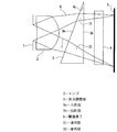
図1は、焦点調整機構の構成を示し、符号1は絞り、2はレンズ、3は焦点調整板、4は赤外線カットフィルター、5はCCD又はCMOS等の撮像素子である。その焦点調整板3は、入射面3aと出射面3bとが所定の傾斜角度R1をなす一枚の光学素材からなり、その入射面3a又は出射面3bの何れか一方(図示の例では出射面3b)を光軸方向に略直交させて、この焦点調整板3をレンズ2と撮像素子5との間に配設しており、その撮像素子5は光軸方向に直交させるように立設している。
FIG. 1 shows a configuration of a focus adjustment mechanism, where reference numeral 1 is an aperture, 2 is a lens, 3 is a focus adjustment plate, 4 is an infrared cut filter, and 5 is an image sensor such as a CCD or CMOS. The
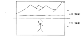
このような構成によれば、レンズ2と撮像素子5との間に配設した焦点調整板3の薄肉部31を透過した撮影光が近距離撮影光6として撮像素子5に入射され、厚肉部32を透過した撮影光が遠距離撮影光7として撮像素子5に入射されるため、例えば、図2に示すように、撮像画面の上半分では遠方の景色を鮮明に撮影し、下半分では近くの人物を鮮明に撮影することができ、遠近両方の焦点の調整が可能となる。
According to such a configuration, the photographing light transmitted through the
以上のように、一枚の焦点調整板3をレンズ2と撮像素子5との間に配設したきわめて簡易な構成により、遠近両方の焦点補正(あおり補正)が可能となるので、デジタルカメラをコンパクトに形成することができ、かつ、安価に提供することができる。
As described above, since a single
なお、本発明は、前記実施形態に限定することなく、特許請求の範囲に記載した技術的事項の範囲内において種々変更することができる。 In addition, this invention can be variously changed within the range of the technical matter described in the claim, without being limited to the said embodiment.
例えば、図示しないが、上述したような焦点調整板3において、入射面3aと出射面3bとが平行となる部分をさらに設け、この平行部分に撮影光を透過させることにより、前記したようなあおり補正を行わない撮影にも対応することができる。
For example, although not shown, in the
また、焦点調整板3は、入射面3aと出射面3bとが所定の傾斜角度R1をなすものであれば、あらゆる形状のものが考えられ、また、入射面3aもしくは出射面3bは、撮影光6cに対して略直交である必要はなく、どのような角度に配置してもよい。
The
本発明にかかる焦点調整機構は、入射面と出射面とが所定の傾斜角度をなし薄肉部から厚肉部へと肉厚が変化する一枚の光学素材からなる焦点調整板をレンズと撮像素子との間に配設し、その焦点調整板の薄肉部を透過した撮影光を近距離撮影光として撮像素子に入射させ、厚肉部を透過した撮影光を遠距離撮影光として撮像素子に入射させることにより、遠近両方の焦点の補正(あおり補正)を行うので、光学系をきわめてコンパクトに構成することができるため、特に、デジタルカメラ等に有用である。 The focus adjustment mechanism according to the present invention includes a lens and an image pickup element, each of which includes a focus adjustment plate made of a single optical material in which the incident surface and the output surface have a predetermined inclination angle and the thickness changes from the thin portion to the thick portion. The photographic light transmitted through the thin part of the focus adjustment plate is incident on the image sensor as short-distance photographic light, and the photographic light transmitted through the thick part is incident on the image sensor as long-distance photographic light. By doing so, both focal points are corrected (tilt correction), so that the optical system can be made very compact, and is particularly useful for digital cameras and the like.
本発明にかかる焦点調整機構は、入射面と出射面とが所定の傾斜角度をなし薄肉部から厚肉部へと肉厚が変化する一枚の光学素材からなる焦点調整板をレンズと撮像素子との間に配設し、その焦点調整板の薄肉部を透過した撮影光を近距離撮影光として撮像素子に入射させ、厚肉部を透過した撮影光を遠距離撮影光として撮像素子に入射させることにより、遠近両方の焦点の補正(あおり補正)を行うので、光学系をきわめてコンパクトに構成することが要求される小型カメラ等の技術分野に広く適用できる。 The focus adjustment mechanism according to the present invention includes a lens and an image pickup element, each of which includes a focus adjustment plate made of a single optical material in which the incident surface and the output surface have a predetermined inclination angle and the thickness changes from the thin portion to the thick portion. The photographic light transmitted through the thin part of the focus adjustment plate is incident on the image sensor as short-distance photographic light, and the photographic light transmitted through the thick part is incident on the image sensor as long-distance photographic light. By doing so, both near and far focus corrections (tilt correction) are performed, and therefore, the present invention can be widely applied to technical fields such as small cameras that require an extremely compact optical system.
2 レンズ
3 焦点調整板
3a 入射面
3b 出射面
31 薄肉部
32 厚肉部
5 撮像素子
6 近距離撮影光
7 遠距離撮影光
2
Claims (2)
The focus adjustment plate further includes a parallel portion in which the incident surface and the exit surface are formed in parallel, and the photographing light is transmitted to either the inclined portion or the parallel portion by moving the focus adjustment plate. The focus adjusting mechanism according to claim 1, wherein:
Priority Applications (1)
| Application Number | Priority Date | Filing Date | Title |
|---|---|---|---|
| JP2004108856A JP2005292544A (en) | 2004-04-01 | 2004-04-01 | Focusing mechanism |
Applications Claiming Priority (1)
| Application Number | Priority Date | Filing Date | Title |
|---|---|---|---|
| JP2004108856A JP2005292544A (en) | 2004-04-01 | 2004-04-01 | Focusing mechanism |
Publications (1)
| Publication Number | Publication Date |
|---|---|
| JP2005292544A true JP2005292544A (en) | 2005-10-20 |
Family
ID=35325516
Family Applications (1)
| Application Number | Title | Priority Date | Filing Date |
|---|---|---|---|
| JP2004108856A Pending JP2005292544A (en) | 2004-04-01 | 2004-04-01 | Focusing mechanism |
Country Status (1)
| Country | Link |
|---|---|
| JP (1) | JP2005292544A (en) |
Cited By (10)
| Publication number | Priority date | Publication date | Assignee | Title |
|---|---|---|---|---|
| JP2007233950A (en) * | 2006-03-03 | 2007-09-13 | Glory Ltd | Image authentication device, imaging device and image authentication system |
| WO2011003381A1 (en) | 2009-07-06 | 2011-01-13 | Conti Temic Microelectronic Gmbh | Optical module for simultaneously focusing on two fields of view |
| KR20110105837A (en) * | 2008-12-23 | 2011-09-27 | 에이디씨 오토모티브 디스턴스 컨트롤 시스템즈 게엠베하 | Optical module having multifocal lens for detecting far and near fields in an image |
| WO2011153978A3 (en) * | 2010-06-11 | 2012-02-16 | Conti Temic Microelectronic Gmbh | Optical element for multifocal imaging in a camera for vehicle applications |
| US8593552B2 (en) | 2007-08-04 | 2013-11-26 | Omnivision Technologies, Inc. | Image based systems for detecting information on moving objects |
| US8729653B2 (en) | 2011-10-26 | 2014-05-20 | Omnivision Technologies, Inc. | Integrated die-level cameras and methods of manufacturing the same |
| US9335264B2 (en) | 2010-11-30 | 2016-05-10 | Conti Temic Microelectronic Gmbh | Detection of raindrops on a pane by means of a camera and lighting |
| US9508015B2 (en) | 2011-12-05 | 2016-11-29 | Continental Teves Ag & Co. Ohg | Method for evaluating image data of a vehicle camera taking into account information about rain |
| US9702818B2 (en) | 2012-05-03 | 2017-07-11 | Conti Temic Microelectronic Gmbh | Detection of raindrops on a windowpane by means of camera and light |
| US10137842B2 (en) | 2011-06-03 | 2018-11-27 | Conti Temic Microelectronic Gmbh | Camera system for a vehicle |
-
2004
- 2004-04-01 JP JP2004108856A patent/JP2005292544A/en active Pending
Cited By (18)
| Publication number | Priority date | Publication date | Assignee | Title |
|---|---|---|---|---|
| JP4680100B2 (en) * | 2006-03-03 | 2011-05-11 | グローリー株式会社 | Image authentication apparatus, photographing apparatus, and image authentication system |
| JP2007233950A (en) * | 2006-03-03 | 2007-09-13 | Glory Ltd | Image authentication device, imaging device and image authentication system |
| EP2183635B1 (en) * | 2007-08-04 | 2015-09-16 | Omnivision Technologies, Inc. | Multi-region imaging systems |
| US8593552B2 (en) | 2007-08-04 | 2013-11-26 | Omnivision Technologies, Inc. | Image based systems for detecting information on moving objects |
| US8736699B2 (en) | 2007-08-04 | 2014-05-27 | Omnivision Technologies, Inc. | Multi-region imaging systems |
| US9471994B2 (en) | 2007-08-04 | 2016-10-18 | Omnivision Technologies, Inc. | Image based systems for detecting information on moving objects |
| KR20110105837A (en) * | 2008-12-23 | 2011-09-27 | 에이디씨 오토모티브 디스턴스 컨트롤 시스템즈 게엠베하 | Optical module having multifocal lens for detecting far and near fields in an image |
| US8541732B2 (en) | 2008-12-23 | 2013-09-24 | Adc Automotive Distance Control Systems Gmbh | Optical module having a multifocal optical system with an additional optical element for covering a far range and a near range in one image |
| KR101871731B1 (en) | 2008-12-23 | 2018-06-27 | 에이디씨 오토모티브 디스턴스 컨트롤 시스템즈 게엠베하 | Optical module having multifocal lens for detecting far and near fields in an image |
| WO2011003381A1 (en) | 2009-07-06 | 2011-01-13 | Conti Temic Microelectronic Gmbh | Optical module for simultaneously focusing on two fields of view |
| US9040915B2 (en) | 2009-07-06 | 2015-05-26 | Conti Temic Microelectronic Gmbh | Optical module for simultaneously focusing on two fields of view |
| WO2011153978A3 (en) * | 2010-06-11 | 2012-02-16 | Conti Temic Microelectronic Gmbh | Optical element for multifocal imaging in a camera for vehicle applications |
| US9335264B2 (en) | 2010-11-30 | 2016-05-10 | Conti Temic Microelectronic Gmbh | Detection of raindrops on a pane by means of a camera and lighting |
| US10137842B2 (en) | 2011-06-03 | 2018-11-27 | Conti Temic Microelectronic Gmbh | Camera system for a vehicle |
| US8846435B2 (en) | 2011-10-26 | 2014-09-30 | Omnivision Technologies, Inc. | Integrated die-level cameras and methods of manufacturing the same |
| US8729653B2 (en) | 2011-10-26 | 2014-05-20 | Omnivision Technologies, Inc. | Integrated die-level cameras and methods of manufacturing the same |
| US9508015B2 (en) | 2011-12-05 | 2016-11-29 | Continental Teves Ag & Co. Ohg | Method for evaluating image data of a vehicle camera taking into account information about rain |
| US9702818B2 (en) | 2012-05-03 | 2017-07-11 | Conti Temic Microelectronic Gmbh | Detection of raindrops on a windowpane by means of camera and light |
Similar Documents
| Publication | Publication Date | Title |
|---|---|---|
| US9686471B2 (en) | Methods and apparatus relating to image stabilization | |
| US7679645B2 (en) | Image sensing system and its control method | |
| JP5296307B2 (en) | System and method for improving autofocus in a digital imaging system | |
| CN105376475B (en) | The control method of image stabilizing device and image stabilizing device | |
| JPH07307889A (en) | Automatic exposure control camera using variable exposure index ccd sensor | |
| JP2005004181A (en) | Visible light/infrared light photographing lens system | |
| WO2021017683A1 (en) | Optical anti-shake apparatus and control method | |
| JP2005292544A (en) | Focusing mechanism | |
| JP6444025B2 (en) | Optical equipment | |
| JP4887828B2 (en) | Digital camera | |
| JP2003185902A (en) | Camera | |
| JP2006235071A (en) | Imaging apparatus | |
| JP2010117591A (en) | Imaging device | |
| JP2005300659A (en) | Dome type camera and dome cover | |
| JP2008028591A (en) | Image processing method in imaging device, and imaging device | |
| JP2009218661A (en) | Imaging device with image distortion correcting function | |
| JP4563277B2 (en) | Imaging apparatus having a plurality of optical systems | |
| JP4983286B2 (en) | camera | |
| JP2007110498A (en) | Compound eye photographing apparatus | |
| JP2007057553A (en) | Image pickup device | |
| JP2001042380A (en) | Photographing device | |
| JP2006229697A (en) | Image pickup device | |
| KR100860700B1 (en) | Realizing method of depth of field and digital camera using thereof | |
| JP2009151155A (en) | Focus detecting device, focus adjusting device and imaging apparatus | |
| JP2007060010A (en) | Camera system |