JP2005292404A - Accessory device - Google Patents

Accessory device Download PDF

Info

Publication number
JP2005292404A
JP2005292404A JP2004106247A JP2004106247A JP2005292404A JP 2005292404 A JP2005292404 A JP 2005292404A JP 2004106247 A JP2004106247 A JP 2004106247A JP 2004106247 A JP2004106247 A JP 2004106247A JP 2005292404 A JP2005292404 A JP 2005292404A
Authority
JP
Japan
Prior art keywords
accessory device
optical
optical device
adhesive
state
Prior art date
Legal status (The legal status is an assumption and is not a legal conclusion. Google has not performed a legal analysis and makes no representation as to the accuracy of the status listed.)
Withdrawn
Application number
JP2004106247A
Other languages
Japanese (ja)
Inventor
Goro Noto
悟郎 能登
Current Assignee (The listed assignees may be inaccurate. Google has not performed a legal analysis and makes no representation or warranty as to the accuracy of the list.)
Canon Inc
Original Assignee
Canon Inc
Priority date (The priority date is an assumption and is not a legal conclusion. Google has not performed a legal analysis and makes no representation as to the accuracy of the date listed.)
Filing date
Publication date
Application filed by Canon Inc filed Critical Canon Inc
Priority to JP2004106247A priority Critical patent/JP2005292404A/en
Publication of JP2005292404A publication Critical patent/JP2005292404A/en
Withdrawn legal-status Critical Current

Links

Images

Landscapes

  • Accessories Of Cameras (AREA)

Abstract

<P>PROBLEM TO BE SOLVED: To remove, by a simple operation, foreign matters sticking to the surface of the cover glass of a solid-state state imaging device or the surface of an optical filter. <P>SOLUTION: The accessory device removes foreign matters sticking to the surface of an optical member. The accessory device includes a support section 51; an approximately V-shaped flexible section 52 so disposed as to be integrated with the support section 51; elastic sections 53 attached to the flexible section 52; a sticky section 54 extended between the elastic sections 53; and an attachable section 56 which is attached to the mounting mechanism of a camera. While being kept attached to the mounting mechanism of the camera, the support section 55 is pushed to push in the sticky section 54; and thereby, foreign matters sticking to the filter face, etc., in the camera are removed. <P>COPYRIGHT: (C)2006,JPO&NCIPI

Description

本発明は、例えばデジタルカメラ等の光学機器のアクセサリ装置に関し、特に光学機器に組み込まれている光学部材の表面或はその近傍に付着した異物を除去するためのアクセサリ装置に関するものである。   The present invention relates to an accessory device for an optical device such as a digital camera, and more particularly to an accessory device for removing foreign matter adhering to or near the surface of an optical member incorporated in the optical device.

カメラの撮影レンズの焦点面近傍に塵埃等の異物が存在すると、その異物の影が固体撮像素子に写り込んでしまうという問題がある。このような異物は、レンズ交換時に塵埃が外部から侵入したり、カメラ内部でのシャッタやミラーの動作に伴い、その構造部材である樹脂等の微細な磨耗紛が発生することが原因と考えられている。このような原因で発生した塵埃が、特に固体撮像素子の保護用のカバーガラスとカバーガラスの全面に配設されている赤外カットフィルタや光学ローパスフィルタ(以下、LPFと略す)等の光学フィルタの間に入り込んでしまった場合には、その塵埃を除去するためにカメラを分解しなければならなかった。このため、固体撮像素子のカバーガラスと光学フィルタとの間に塵埃が入り込まないように密閉構造にすることは極めて有効なものであった。   If there is a foreign object such as dust near the focal plane of the camera's taking lens, there is a problem that the shadow of the foreign object is reflected on the solid-state image sensor. Such foreign matter is thought to be caused by dust entering from the outside when the lens is replaced, or by fine abrasion powder such as resin, which is a structural member, due to the operation of the shutter and mirror inside the camera. ing. An optical filter such as an infrared cut filter or an optical low-pass filter (hereinafter abbreviated as LPF) in which dust generated due to such a cause is disposed on the entire surface of the cover glass for protecting the solid-state image sensor and the cover glass. If it got in between, the camera had to be disassembled to remove the dust. For this reason, it has been extremely effective to provide a sealed structure so that dust does not enter between the cover glass of the solid-state imaging device and the optical filter.

しかしながら、光学フィルタの固体撮像素子に対向側と反対の表面に塵埃が付着した場合、それが焦点面の近傍である場合にはその塵埃が影となって固体撮像素子に写り込んでしまうという問題が依然として残っている。   However, when dust adheres to the surface opposite to the opposite side of the solid-state image sensor of the optical filter, if it is in the vicinity of the focal plane, the dust is reflected in the solid-state image sensor as a shadow. Still remains.

そこで、このような問題点を解決するために、固体撮像素子のカバーガラスの表面もしくは防塵構造の最外面をワイパーで清掃するものがある(特許文献1参照)。このようなカメラ構成にすると、レンズを外さず、またカメラを分解することなく固体撮像素子のカバーガラス表面又は防塵構造の最外面(例えば光学フィルタ表面)に付着した塵埃を除去することができる。
特開2003-018440号公報 実開平06-063183号公報
Therefore, in order to solve such problems, there is one that cleans the surface of the cover glass of the solid-state imaging device or the outermost surface of the dustproof structure with a wiper (see Patent Document 1). With such a camera configuration, dust attached to the cover glass surface of the solid-state imaging device or the outermost surface of the dust-proof structure (for example, the optical filter surface) can be removed without removing the lens and without disassembling the camera.
JP 2003-018440 A Japanese Utility Model Publication No. 06-063183

しかしながら特許文献1の構成では、固体撮像素子のカバーガラスの表面や防塵構造の最外面をワイパーで擦るため、金属紛のような硬い塵埃の場合には、固体撮像素子のカバーガラスの表面や防塵構造の最外面にキズを付ける可能性がある。またワイパーを配設するための機構が必要となり、カメラが大型化するという問題がある。   However, in the configuration of Patent Document 1, the surface of the cover glass of the solid-state image sensor and the outermost surface of the dust-proof structure are rubbed with a wiper. Therefore, in the case of hard dust such as metal powder, the surface of the cover glass of the solid-state image sensor and the dust proof There is a possibility of scratching the outermost surface of the structure. In addition, a mechanism for disposing the wiper is required, and there is a problem that the camera becomes large.

そこで、粘着性を有する清掃棒により、付着している塵埃を清掃対象物から除去するものがある(特許文献2)。これは棒状部材の一端部にクッション材を介して粘着材を配設しクッション性と粘着性を併せ持った清掃部を備えた粘着性清掃棒により、固体撮像素子のカバーガラスの表面や光学フィルタの表面に付着した塵埃を取り除くものである。しかしながら、このような粘着性清掃棒を用いて清掃する場合、固体撮像素子のカバーガラスの表面や光学フィルタの表面に付着した塵埃が少なければ比較的簡単に取り除くことができるが、多くの塵埃が付着した場合には、複数回の除去作業が必要になる。   Then, there exists a thing which removes the adhering dust from a cleaning target object with the cleaning stick which has adhesiveness (patent documents 2). This is because an adhesive material is disposed on one end of a rod-like member via a cushioning material, and has a cleaning part having both cushioning properties and adhesiveness. It removes dust adhering to the surface. However, when cleaning with such an adhesive cleaning rod, it can be removed relatively easily if there is little dust adhering to the surface of the cover glass of the solid-state imaging device or the surface of the optical filter. If it adheres, multiple removal operations are required.

また、このような構成では、粘着性の清掃棒をカメラ内の清掃対象部以外に接触させてカメラ内部を汚染させたり、或は精密な機構部分に誤って挿入してしまい、専門家による修理が必要となるなどの虞がある。   In addition, in such a configuration, the sticky cleaning rod is brought into contact with a part other than the cleaning target part in the camera to contaminate the inside of the camera, or it is erroneously inserted into a precise mechanism part, and repaired by a specialist. May be necessary.

本発明は上記問題点に鑑みてなされたもので、本願発明の特徴は、光学機器の清掃対象面以外に接触する危険性をなくしたアクセサリ装置を提供することにある。   The present invention has been made in view of the above problems, and a feature of the present invention is to provide an accessory device that eliminates the risk of contact with surfaces other than the surface to be cleaned of an optical device.

本発明に係る光学機器のアクセサリ装置は以下のような構成を備える。即ち、
光学機器に取り付けられ、当該光学機器が有する光学部材の表面及び/或はその近傍に付着した異物を除去するアクセサリ装置であって、
ユーザにより支持・操作される操作部と、
前記操作部と一体的に形成され略V字型を有する可撓部と、
前記可撓部に懸架された弾性部と、
前記弾性部の少なくとも先端部側に設けられた粘着部と、
前記光学機器のマウント機構と係合して当該アクセサリ装置を前記光学機器に取り付けるための取り付け機構とを有し、
前記取り付け機構により当該アクセサリ装置を前記光学機器に取り付けた状態で前記操作部が操作されることにより前記粘着部が前記光学機器内に進入して異物を除去することを特徴とする。
The accessory device for an optical apparatus according to the present invention has the following configuration. That is,
An accessory device that is attached to an optical device and removes foreign matter adhering to and / or near the surface of an optical member of the optical device,
An operation unit supported and operated by a user;
A flexible part integrally formed with the operation part and having a substantially V-shape;
An elastic part suspended from the flexible part;
An adhesive portion provided on at least the tip side of the elastic portion;
An attachment mechanism for engaging with the mount mechanism of the optical device and attaching the accessory device to the optical device;
When the operation unit is operated in a state where the accessory device is attached to the optical device by the attachment mechanism, the adhesive unit enters the optical device and removes foreign matter.

また本発明に係る光学機器のアクセサリ装置は以下のような構成を備える。即ち、
光学機器に取り付けられ、当該光学機器が有する光学部材の表面及び/或はその近傍に付着した異物を除去するアクセサリ装置であって、
軸部の端部に設けられユーザにより操作される操作部と、
前記操作部と反対側の前記軸部の端部に設けられ略V字型を有する可撓部と、
前記可撓部に懸架された弾性部と、
前記弾性部の少なくとも先端部側に設けられた粘着部と、
前記光学機器のマウント機構と係合して当該アクセサリ装置を前記光学機器に取り付けるための取り付け機構とを有し、
前記取り付け機構により当該アクセサリ装置を前記光学機器に取り付けた状態で前記操作部が操作されることにより前記粘着部が前記光学機器内に進入して異物を除去することを特徴とする。
An accessory device for an optical apparatus according to the present invention has the following configuration. That is,
An accessory device that is attached to an optical device and removes foreign matter adhering to and / or near the surface of an optical member of the optical device,
An operation unit provided at an end of the shaft unit and operated by a user;
A flexible portion provided at the end of the shaft portion opposite to the operation portion and having a substantially V-shape;
An elastic part suspended from the flexible part;
An adhesive portion provided on at least the tip side of the elastic portion;
An attachment mechanism for engaging with the mount mechanism of the optical device and attaching the accessory device to the optical device;
When the operation unit is operated in a state where the accessory device is attached to the optical device by the attachment mechanism, the adhesive unit enters the optical device and removes foreign matter.

また本発明に係る光学機器のアクセサリ装置は以下のような構成を備える。即ち、
光学機器に取り付けられ、当該光学機器が有する光学部材の表面及び/或はその近傍に付着した異物を除去するアクセサリ装置であって、
ユーザにより支持・操作される操作部と、粘着面を具備する粘着部と、可撓性を有し、前記操作部に対して前記粘着面を略直交するように展開して保持する可撓部と、前記光学機器のマウント機構と係合して当該アクセサリ装置を前記光学機器に取り付けるための取り付け機構とを有し、前記取り付け機構により当該アクセサリ装置を前記光学機器に取り付けた状態で前記操作部が操作されることにより前記粘着部が前記光学機器内に進入して異物を除去することを特徴とする。
An accessory device for an optical apparatus according to the present invention has the following configuration. That is,
An accessory device that is attached to an optical device and removes foreign matter adhering to and / or near the surface of an optical member of the optical device,
An operation part supported and operated by a user, an adhesive part having an adhesive surface, and a flexible part that has flexibility and expands and holds the adhesive surface substantially orthogonal to the operation part. And an attachment mechanism for attaching the accessory device to the optical device by engaging with a mount mechanism of the optical device, and the operation unit in a state where the accessory device is attached to the optical device by the attachment mechanism. Is operated, the adhesive portion enters the optical device to remove foreign matter.

また本発明に係る光学機器のアクセサリ装置は以下のような構成を備える。即ち、
光学機器に取り付けられ、当該光学機器が有する光学部材の表面及び/或はその近傍に付着した異物を除去するアクセサリ装置であって、
軸部の端部に設けられユーザにより操作される操作部と、粘着面を具備する粘着部と、可撓制を有し、前記軸部と前記粘着面が略直交するように接続して保持する可撓部と、前記光学機器のマウント機構と係合して当該アクセサリ装置を前記光学機器に取り付けるための取り付け機構とを有し、前記取り付け機構により当該アクセサリ装置を前記光学機器に取り付けた状態で前記操作部が操作されることにより前記粘着部が前記光学機器内に進入して異物を除去することを特徴とする。
An accessory device for an optical apparatus according to the present invention has the following configuration. That is,
An accessory device that is attached to an optical device and removes foreign matter adhering to and / or near the surface of an optical member of the optical device,
An operation unit provided at an end portion of the shaft portion, which is operated by a user, an adhesive portion having an adhesive surface, and a flexible system, connected and held so that the shaft portion and the adhesive surface are substantially orthogonal to each other. A flexible portion that engages with a mounting mechanism of the optical device and a mounting mechanism for mounting the accessory device to the optical device, and the accessory device is attached to the optical device by the mounting mechanism. When the operation unit is operated, the adhesive unit enters the optical device and removes foreign matter.

本発明によれば、付着した異物を除去する際に光学機器の清掃対象面以外に接触する危険性がなく、かつ簡単に異物を除去することができるいという効果がある。   ADVANTAGE OF THE INVENTION According to this invention, when removing the adhering foreign material, there exists an effect that there is no danger of contacting except the surface to be cleaned of an optical apparatus, and it is easy to remove a foreign material.

以下、添付図面を参照して本発明の好適な実施の形態を詳しく説明する。   Hereinafter, preferred embodiments of the present invention will be described in detail with reference to the accompanying drawings.

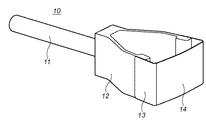
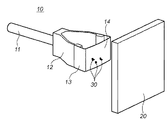
図1は、本発明の参考例であるアクセサリ装置10の構成を示す概観斜視図である。   FIG. 1 is a schematic perspective view showing a configuration of an accessory device 10 which is a reference example of the present invention.

図において、アクセサリ装置10は、塵埃を除去する際にアクセサリ装置10をユーザが支持する支持部11、支持部11と一体的に設けられ、略V型で可撓性を備えている可撓部12、この可撓部12に一体的に懸架されており、略コの字型をしている弾性部13及び弾性部13の先端に設けられた粘着部14とを備えている。   In the figure, an accessory device 10 is provided integrally with a support portion 11 and a support portion 11 that support the accessory device 10 by a user when dust is removed, and is a substantially V-shaped flexible portion. 12, an elastic part 13 which is suspended integrally with the flexible part 12 and has a substantially U-shape, and an adhesive part 14 provided at the tip of the elastic part 13.

尚、粘着部14が設けられている弾性部13の先端部側は、外側にやや膨らんだ略円弧形状を形成している。これによりカメラ内の固体撮像素子のカバーガラスや光学フィルタ等のように、その表面形状が略平面の光学部材に粘着部14が当接する場合は、後述するように、その粘着部14が押し付けられるのに応じて光学部材の中央からその周辺部に向かって徐々に粘着部14が当接することとなる。また、この粘着部14は、粘着テープ(例えば住友3M製両面粘着テープ「9313」)や、もしくは弾性部13の表面にアクリル系等の粘着剤を直接塗布したものでも良い。   In addition, the front-end | tip part side of the elastic part 13 in which the adhesion part 14 is provided forms the substantially circular arc shape which expanded a little outside. As a result, when the adhesive portion 14 comes into contact with an optical member having a substantially flat surface shape, such as a cover glass or an optical filter of a solid-state imaging device in the camera, the adhesive portion 14 is pressed as will be described later. Accordingly, the adhesive portion 14 gradually comes into contact from the center of the optical member toward the peripheral portion thereof. The pressure-sensitive adhesive portion 14 may be a pressure-sensitive adhesive tape (for example, a double-sided pressure-sensitive adhesive tape “9313” manufactured by Sumitomo 3M), or a material obtained by directly applying an acrylic pressure-sensitive adhesive to the surface of the elastic portion 13.

また本発明のアクセサリ装置10は、図1に示すような構成のもに限らず、例えば支持部11の先端、或は支持部11と一体に可撓性を有する柔軟部材で構成されたゴム状の部材を設け、このゴム状の部材により粘着部14である粘着シート(粘着テープ)を広げた(展開させた)状態で保持させたものでも良い。これにより図1の構成と同様に、粘着シートによりゴミなどの異物を除去でき、またゴム状の部材が緩衝材として機能しているため、光学機器の内部を傷付けないようにしてゴミを除去できる。   Further, the accessory device 10 of the present invention is not limited to the configuration shown in FIG. 1, for example, the tip of the support portion 11, or a rubber-like shape formed of a flexible member having flexibility integrally with the support portion 11. These members may be provided, and the rubber sheet may be used to hold the adhesive sheet (adhesive tape) that is the adhesive part 14 in a state of being expanded (deployed). As in the configuration of FIG. 1, foreign substances such as dust can be removed by the adhesive sheet, and since the rubber-like member functions as a cushioning material, dust can be removed without damaging the inside of the optical device. .

図2は、本参考例に係るアクセサリ装置10を用いて、固体撮像素子のカバーガラスの表面もしくは光学フィルタの表面等に付着した塵埃を除去する対象機器である光学機器の一例であるデジタルカラーカメラ(以下、単にカメラと呼ぶ)100の構成を説明するための側方視断面図である。   FIG. 2 shows a digital color camera that is an example of an optical device that is a target device that removes dust adhering to the surface of the cover glass of the solid-state imaging device or the surface of the optical filter using the accessory device 10 according to the present reference example. 1 is a side view sectional view for explaining a configuration of 100 (hereinafter simply referred to as a camera).

このカメラ100は、CCD或はCMOSセンサなどの固体撮像素子を用いた単板式のカメラ(一眼レフカメラ)であり、固体撮像素子を連続的又は単発的に駆動して、動画像或は静止画像を表わす画像信号を得る。ここで固体撮像素子は、露光した光を画素毎に電気信号に変換し、その光量に応じた電荷をそれぞれ蓄積し、その電荷を読み出すタイプのエリアセンサである。   This camera 100 is a single-plate camera (single-lens reflex camera) using a solid-state image pickup device such as a CCD or a CMOS sensor. The solid-state image pickup device is continuously or once driven to generate a moving image or a still image. Is obtained. Here, the solid-state imaging device is an area sensor of a type that converts exposed light into an electrical signal for each pixel, accumulates charges corresponding to the light amount, and reads the charges.

図2において、100はカメラ本体、101はマウント機構であり、不図示の撮影レンズ(内部に絞りと結像光学系を有して取り外し可能)は、このマウント機構101を介してカメラ100本体に電気的及び機械的に接続される。このようなデジタル一眼レフカメラでは、撮影に使用する撮影レンズを焦点距離の異なるレンズに交換することにより、様々な画角の撮影画面を得ることができる。固体撮像素子106は、パッケージ124に収納されており、このパッケージ124はカバーガラス125にて固体撮像素子106を密閉状態で保持している。そして、不図示の撮影レンズ内の結像光学系から固体撮像素子106に至る光路中には、固体撮像素子106上に物体像の必要以上に高い空間周波数成分が伝達されないように結像光学系のカットオフ周波数を制限する光学ローパスフィルタ156(以下、LPF156と略す)が設けられている。また、この結像光学系には赤外線カットフィルタも形成されている。更に、カバーガラス125とLPF156との間は両面テープ等の密封部材157にて密封構造となっているので、カメラ100の外部もしくはカメラ100内部で発生した塵埃が、これらLPF156とカバーガラス125との間に入り込まないようになっている。   In FIG. 2, reference numeral 100 denotes a camera body, and 101 denotes a mount mechanism. A photographing lens (not shown) (which can be removed with an aperture and an imaging optical system inside) is attached to the camera 100 body via the mount mechanism 101. Electrically and mechanically connected. In such a digital single lens reflex camera, it is possible to obtain shooting screens with various angles of view by exchanging the shooting lens used for shooting with a lens having a different focal length. The solid-state image sensor 106 is housed in a package 124, and the package 124 holds the solid-state image sensor 106 in a sealed state with a cover glass 125. Then, in the optical path from the imaging optical system in the imaging lens (not shown) to the solid-state image sensor 106, the image-forming optical system prevents the spatial frequency component higher than necessary from being transmitted on the solid-state image sensor 106. There is provided an optical low-pass filter 156 (hereinafter abbreviated as LPF 156) for limiting the cut-off frequency. An infrared cut filter is also formed in this imaging optical system. Further, since the cover glass 125 and the LPF 156 have a sealing structure with a sealing member 157 such as a double-sided tape, dust generated outside the camera 100 or inside the camera 100 is caused between the LPF 156 and the cover glass 125. It is designed not to get in between.

固体撮像素子106で捉えられた物体像は、ディスプレイ107に表示される。このディスプレイ107は、このカメラ100の背面に取り付けられており、撮影時等において、使用者は、その撮影対象の画像をこのディスプレイ107により直接観察できる。このディスプレイ107は、有機EL空間変調素子や液晶空間変調素子、微粒子の電気泳動を利用した空間変調素子などで構成すると消費電力が小さく、かつ薄型で都合が良い。また固体撮像素子106は、増幅型固体撮像素子の一つであるCMOSプロセスコンパチブルのセンサ(以下、CMOSセンサと略す)である。このCMOSセンサの特徴の一つに、エリアセンサ部のMOSトランジスタと撮像素子の駆動回路、A/D変換回路、画像処理回路といった周辺回路(図3参照)を同一工程で形成できることが挙げられる。この特徴により、マスク枚数、プロセス工程がCCDと比較して大幅に削減できる。また、任意の画素へのランダムアクセスが可能といった特長も有し、ディスプレイ用に画素を間引いた読み出しが容易で、高い表示レートでリアルタイム表示が行える。固体撮像素子106は、このような特徴を利用し、ディスプレイ107の画像出力動作、高精彩画像出力動作を行う。   The object image captured by the solid-state image sensor 106 is displayed on the display 107. The display 107 is attached to the rear surface of the camera 100, and the user can directly observe the image to be photographed with the display 107 during photographing. If the display 107 is composed of an organic EL spatial modulation element, a liquid crystal spatial modulation element, a spatial modulation element using fine particle electrophoresis, etc., it is convenient because it consumes less power and is thin. The solid-state image sensor 106 is a CMOS process compatible sensor (hereinafter abbreviated as a CMOS sensor), which is one of amplification type solid-state image sensors. One of the features of this CMOS sensor is that peripheral circuits (see FIG. 3) such as a MOS transistor in the area sensor section and an image sensor driving circuit, an A / D conversion circuit, and an image processing circuit can be formed in the same process. With this feature, the number of masks and process steps can be greatly reduced as compared with the CCD. In addition, it has a feature that random access to an arbitrary pixel is possible, and readout by thinning out pixels for display is easy, and real-time display can be performed at a high display rate. The solid-state imaging element 106 performs such an image output operation and a high-definition image output operation of the display 107 using such features.

ハーフミラー111は、光学ファインダに不図示の結像光学系からの光路を分割する可動型のミラーである。フォーカシングスクリーン105は、物体像の予定結像面に配置されている。112はペンタプリズムである。レンズ109は、撮影時、ユーザが光学ファインダ像を観察するためのレンズであり、実際には3つのレンズで構成されている。フォーカシングスクリーン105、ペンタプリズム112、レンズ109はファインダ光学系を構成している。ここでハーフミラー111の屈折率はおよそ1.5、厚さは0.5mmである。このハーフミラー111の背後には可動型のサブミラー122が設けられており、ハーフミラー111を透過した光束の内、光軸に近い光束を焦点検出部121に偏向している。サブミラー122は、ハーフミラー111の保持部材(不図示)に設けられた回転軸を中心に回転し、ハーフミラー111の動きに連動して移動する。尚、この焦点検出部121は位相差検出方式の焦点検出を行う。   The half mirror 111 is a movable mirror that divides an optical path from an imaging optical system (not shown) in the optical viewfinder. The focusing screen 105 is disposed on the planned image plane of the object image. Reference numeral 112 denotes a pentaprism. The lens 109 is a lens for the user to observe the optical viewfinder image at the time of shooting, and actually includes three lenses. The focusing screen 105, the pentaprism 112, and the lens 109 constitute a finder optical system. Here, the half mirror 111 has a refractive index of about 1.5 and a thickness of 0.5 mm. A movable sub-mirror 122 is provided behind the half mirror 111, and deflects a light beam close to the optical axis among the light beams transmitted through the half mirror 111 to the focus detection unit 121. The sub mirror 122 rotates around a rotation axis provided on a holding member (not shown) of the half mirror 111 and moves in conjunction with the movement of the half mirror 111. The focus detection unit 121 performs focus detection by a phase difference detection method.

ハーフミラー111とサブミラー122からなる光路分割系は、上述のファインダ光学系に光を導くための第1の光路分割状態、不図示の結像レンズからの光束をダイレクトに固体撮像素子106に導くために撮影光路から退避した第2の光路分割状態(図2の破線で示した位置:111a及び122a)を取ることができる。   The optical path splitting system including the half mirror 111 and the sub mirror 122 is a first optical path splitting state for guiding light to the above-described finder optical system, and directly guides a light beam from an imaging lens (not shown) to the solid-state image sensor 106. The second optical path split state (positions indicated by broken lines in FIG. 2: 111a and 122a) retracted from the photographing optical path can be taken.

104は可動式の閃光発光部(ストロボ)、113はフォーカルプレンシャッタ、119はメインスイッチ、120はレリーズボタンである。モード切替えスイッチ123は、カメラ100のLPF156の表面等に付着した塵埃をアクセサリ装置10を使用して除去するために、カメラ100をクリーニングモードに設定するためのスイッチである。180は、光学ファインダ内の表示部である。   Reference numeral 104 denotes a movable flash light emitting unit (strobe), 113 a focal plane shutter, 119 a main switch, and 120 a release button. The mode changeover switch 123 is a switch for setting the camera 100 to the cleaning mode in order to remove dust attached to the surface of the LPF 156 of the camera 100 using the accessory device 10. Reference numeral 180 denotes a display unit in the optical viewfinder.

尚、モード切り換えスイッチ123が操作されてクリーニングモードが設定されると、ハーフミラー111とサブミラー122が第2の光路分割状態である位置111a及び122aに移動するとともに、フォーカルプレンシャッタ113が開放状態となる。この状態をクリーニングモードと呼ぶ。これによりユーザは、マウント機構101の開口を通して、直接LPF156の表面を目視できる状態となる。従って、この状態で、アクセサリ装置10を使用してLPF156の表面に付着した塵埃を除去できるようになる。   When the mode changeover switch 123 is operated to set the cleaning mode, the half mirror 111 and the sub mirror 122 move to the positions 111a and 122a that are in the second optical path division state, and the focal plane shutter 113 is in the open state. Become. This state is called a cleaning mode. As a result, the user can directly see the surface of the LPF 156 through the opening of the mount mechanism 101. Therefore, in this state, dust attached to the surface of the LPF 156 can be removed using the accessory device 10.

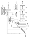
図3は、本実施の形態に係るカメラ100の電気的構成を示すブロック図である。   FIG. 3 is a block diagram showing an electrical configuration of camera 100 according to the present embodiment.

まず物体像の撮像、記録に関する部分から説明する。このカメラ100の機能(機構)としては、撮像機構、画像処理機構、記録再生機構、及び全体の動作制御機構を有する。撮像機構は、不図示の撮影レンズの結像光学レンズ、固体撮像素子106等を含み、画像処理機構は、A/D変換器130、RGB画像処理回路131及びYC処理回路132を含む。また記録再生機構は、記録処理回路133及び再生処理回路134を含む。更に制御機構は、カメラシステム制御回路135、操作検出回路136及び撮像素子駆動回路137を含む。接続端子138は、外部のコンピュータ等に接続して、データの送受信をするための規格化された端子である。これらの電気回路は不図示の小型燃料電池によって駆動される。   First, a description will be given of the part relating to imaging and recording of an object image. Functions (mechanisms) of the camera 100 include an imaging mechanism, an image processing mechanism, a recording / reproducing mechanism, and an overall operation control mechanism. The imaging mechanism includes an imaging optical lens (not shown), a solid-state imaging device 106, and the like, and the image processing mechanism includes an A / D converter 130, an RGB image processing circuit 131, and a YC processing circuit 132. The recording / reproducing mechanism includes a recording processing circuit 133 and a reproduction processing circuit 134. The control mechanism further includes a camera system control circuit 135, an operation detection circuit 136, and an image sensor driving circuit 137. The connection terminal 138 is a standardized terminal for transmitting and receiving data by connecting to an external computer or the like. These electric circuits are driven by a small fuel cell (not shown).

撮像機構は、物体からの光を結像光学系を介して固体撮像素子106の撮像面に結像する光学処理機構を含み、不図示の撮影レンズの絞りと、必要に応じて更にメカニカルシャッタ113を調節し、適切な光量の物体光を固体撮像素子106に露光する。固体撮像素子106は、正方画素が長辺方向に3700個、短辺方向に2800個並べられ、合計約1000万個の画素数を有する撮像素子が適用され、各画素にR(赤色)、G(緑色)、B(青色)のカラーフィルタを交互に配して4画素が一組となる、所謂ベイヤー配列を形成している。このベイヤー配列では、観察者が画像を見たときに強く感じやすいGの画素をRやBの画素よりも多く配置することで、総合的な画像性能を上げている。一般に、この方式の固体撮像素子106を用いる画像処理回路では、輝度信号は主にGから生成し、色信号はR,G,Bから生成している。   The imaging mechanism includes an optical processing mechanism that forms an image of light from an object on an imaging surface of the solid-state imaging device 106 via an imaging optical system, and includes a diaphragm of a photographing lens (not shown), and further a mechanical shutter 113 as necessary. And the solid-state image sensor 106 is exposed to an appropriate amount of object light. In the solid-state imaging device 106, 3700 square pixels are arranged in the long side direction and 2800 are arranged in the short side direction, and an imaging device having a total number of about 10 million pixels is applied, and R (red), G is applied to each pixel. (Green) and B (blue) color filters are alternately arranged to form a so-called Bayer array in which four pixels form a set. In this Bayer arrangement, the overall image performance is improved by arranging more G pixels that are easily felt when an observer sees the image than R and B pixels. In general, in an image processing circuit using this type of solid-state imaging device 106, a luminance signal is generated mainly from G, and a color signal is generated from R, G, and B.

固体撮像素子106から読み出された画像信号は、A/D変換器130によりデジタル画像信号に変換された後、画像処理回路に供給される。A/D変換器130は、露光した各画素からの画像信号の振幅に応じた、例えば10ビットのデジタル信号に変換して出力する信号変換回路であり、これ以降の画像信号処理はデジタル処理にて実行される。この画像処理回路は、R,G,Bのデジタル信号から所望の形式の画像信号を得る信号処理回路であり、R,G,Bの色信号を、輝度信号Y及び色差信号(R−Y),(B−Y)で表わされるYC信号などに変換する。この画像処理回路の構成を以下に説明する。RGB画像処理回路131は、A/D変換器130を介して固体撮像素子106から入力した3700×2800画素の画像信号を処理する信号処理回路であり、ホワイトバランス回路、ガンマ補正回路、補間演算による高解像度化を行う補間演算回路を有する。YC処理回路132は、輝度信号Y及び色差信号R−Y,B−Yを生成する信号処理回路である。また、このYC処理回路132は、高域輝度信号YHを生成する高域輝度信号発生回路、低域輝度信号YLを生成する低域輝度信号発生回路、及び、色差信号R−Y,B−Yを生成する色差信号発生回路で構成されている。また輝度信号Yは高域輝度信号YHと低域輝度信号YLを合成することによって形成される。   The image signal read from the solid-state image sensor 106 is converted into a digital image signal by the A / D converter 130 and then supplied to the image processing circuit. The A / D converter 130 is a signal conversion circuit that converts and outputs, for example, a 10-bit digital signal corresponding to the amplitude of the image signal from each exposed pixel, and the subsequent image signal processing is digital processing. Executed. This image processing circuit is a signal processing circuit that obtains an image signal of a desired format from R, G, B digital signals. The R, G, B color signals are converted into a luminance signal Y and a color difference signal (RY). , (B−Y), and the like. The configuration of this image processing circuit will be described below. The RGB image processing circuit 131 is a signal processing circuit that processes an image signal of 3700 × 2800 pixels input from the solid-state imaging device 106 via the A / D converter 130, and is based on a white balance circuit, a gamma correction circuit, and an interpolation calculation. It has an interpolation operation circuit for increasing the resolution. The YC processing circuit 132 is a signal processing circuit that generates a luminance signal Y and color difference signals RY and BY. The YC processing circuit 132 includes a high-frequency luminance signal generation circuit that generates a high-frequency luminance signal YH, a low-frequency luminance signal generation circuit that generates a low-frequency luminance signal YL, and color difference signals RY and BY. The color difference signal generating circuit for generating The luminance signal Y is formed by combining the high frequency luminance signal YH and the low frequency luminance signal YL.

記録再生機構は、メモリへの画像信号の記憶と、ディスプレイ107への画像信号の出力とを行う処理回路を含み、記録処理回路133はメモリへの画像信号の書き込み処理及び読み出し処理を実行し、再生処理回路134は、そのメモリから読み出した画像信号を再生してディスプレイ107に表示する。   The recording / reproducing mechanism includes a processing circuit that stores the image signal in the memory and outputs the image signal to the display 107. The recording processing circuit 133 executes a writing process and a reading process of the image signal in the memory, The reproduction processing circuit 134 reproduces the image signal read from the memory and displays it on the display 107.

また記録処理回路133は、静止画像及び動画像を表わすYC信号を所定の圧縮形式にて圧縮し、また圧縮データを読み出した際に伸張する圧縮伸張回路を内部に有している。この圧縮伸張回路は、信号処理のためのフレームメモリ等を含み、このフレームメモリに画像処理回路からのYC信号をフレーム毎に蓄積して、それぞれ複数のブロック毎に読み出して圧縮符号化する。この圧縮符号化は、例えば、ブロック毎の画像信号を2次元直交変換、正規化及びハフマン符号化することにより行なわれる。また再生処理回路134は、輝度信号Y及び色差信号R−Y,B−Yをマトリックス変換して、例えばRGB信号に変換する回路である。この再生処理回路134によって変換された信号は、ディスプレイ107に表示されて可視画像として表示再生される。この再生処理回路134とディスプレイ107の間は、例えばブルーツース(Bluetooth)などの無線通信手段を介して接続されてもよい。このように構成することにより、このカメラ100で撮像する画像を離れたところからでもモニタすることができる。   The recording processing circuit 133 includes a compression / expansion circuit that compresses YC signals representing still images and moving images in a predetermined compression format and expands the compressed data when it is read out. The compression / decompression circuit includes a frame memory for signal processing and the like. The YC signal from the image processing circuit is accumulated in the frame memory for each frame, and is read and compressed and encoded for each of a plurality of blocks. This compression coding is performed, for example, by performing two-dimensional orthogonal transformation, normalization, and Huffman coding on the image signal for each block. The reproduction processing circuit 134 is a circuit that performs matrix conversion of the luminance signal Y and the color difference signals RY and BY, for example, into RGB signals. The signal converted by the reproduction processing circuit 134 is displayed on the display 107 and displayed and reproduced as a visible image. The reproduction processing circuit 134 and the display 107 may be connected via wireless communication means such as Bluetooth. With this configuration, an image captured by the camera 100 can be monitored from a distance.

一方、制御機構は、レリーズボタン120やモード切り換えスイッチ123等の操作を検出する操作検出回路136と、その操作検出信号に応動してハーフミラー111やサブミラー122を含む各部を制御し、撮像の際のタイミング信号などを生成して出力するカメラシステム制御回路135と、このカメラシステム制御回路135の制御の下に固体撮像素子106を駆動する駆動信号を生成する固体撮像素子駆動回路137と、光学ファインダ内の表示部180(図2)を制御する情報表示回路142とを含む。この制御機構は、外部操作に応動して撮像機構、画像処理機構、記録再生機構をそれぞれ駆動制御する。例えば、レリーズボタン120の押下を検出して、固体撮像素子106の駆動、RGB画像処理回路131の動作、記録処理回路133の圧縮処理などを制御し、更に情報表示回路142によって光学ファインダ内に情報を表示する表示部180の各セグメントの状態を制御する。   On the other hand, the control mechanism controls the operation detection circuit 136 that detects the operation of the release button 120, the mode changeover switch 123, and the like, and controls each part including the half mirror 111 and the sub mirror 122 in response to the operation detection signal. A camera system control circuit 135 that generates and outputs a timing signal of the image sensor, a solid-state image sensor drive circuit 137 that generates a drive signal for driving the solid-state image sensor 106 under the control of the camera system control circuit 135, and an optical finder. And an information display circuit 142 for controlling the display unit 180 (FIG. 2). This control mechanism drives and controls the imaging mechanism, the image processing mechanism, and the recording / reproducing mechanism in response to an external operation. For example, the depression of the release button 120 is detected to control the driving of the solid-state imaging device 106, the operation of the RGB image processing circuit 131, the compression processing of the recording processing circuit 133, and the like, and further the information in the optical viewfinder by the information display circuit 142. The state of each segment of the display unit 180 that displays “” is controlled.

次に、このカメラ100における焦点調節に関する部分について説明する。   Next, the part regarding the focus adjustment in the camera 100 will be described.

カメラシステム制御回路135には更に、AF制御回路140とレンズシステム制御回路141が接続されている。これらはカメラシステム制御回路135を中心にして、各々の処理に必要とするデータを相互に通信している。AF制御回路140は、撮影画面上の所定の位置に設定された焦点検出視野での焦点検出用センサ167の信号出力を得て、この信号出力に基づいて焦点検出信号を生成し、不図示の撮影レンズの結像光学系の結像状態を検出する。ここでデフォーカスが検出されると、これを結像光学系の一部の要素であるフォーカシングレンズの駆動量に変換し、カメラシステム制御回路135を中継してレンズシステム制御回路141に送信する。また、移動する物体に対しては、レリーズボタン120が押下されてから実際の撮像制御が開始されるまでのタイムラグを勘案し、適切なレンズ位置を予測した結果によるフォーカシングレンズ駆動量を指示する。また、物体の輝度が低く、十分な焦点検出精度が得られないと判定されるときには、閃光発光装置104、或は不図示の白色LEDや蛍光管によって物体を照明する。レンズシステム制御回路141は、フォーカシングレンズの駆動量を受信すると、撮影レンズ内の不図示の駆動機構によってフォーカシングレンズを光軸L1(図2)方向に移動させるなどの動作を行い、物体にピントを合わせる。AF制御回路140によって、物体にピントが合ったことが検出されると、この情報はカメラシステム制御回路135に伝えられる。このとき、レリーズボタン120が押下されれば、前述のごとく撮像系、画像処理系、記録再生系による撮像制御が成される。   An AF control circuit 140 and a lens system control circuit 141 are further connected to the camera system control circuit 135. These communicate with each other data necessary for each processing, centering on the camera system control circuit 135. The AF control circuit 140 obtains a signal output of the focus detection sensor 167 in the focus detection visual field set at a predetermined position on the photographing screen, generates a focus detection signal based on this signal output, and is not shown. The imaging state of the imaging optical system of the photographic lens is detected. When defocusing is detected here, this is converted into a driving amount of a focusing lens that is a part of the imaging optical system, and is relayed to the camera system control circuit 135 and transmitted to the lens system control circuit 141. For a moving object, a focusing lens driving amount based on a result of predicting an appropriate lens position is instructed in consideration of a time lag from when the release button 120 is pressed until actual imaging control is started. When it is determined that the brightness of the object is low and sufficient focus detection accuracy cannot be obtained, the object is illuminated by the flash light emitting device 104 or a white LED or fluorescent tube (not shown). When the lens system control circuit 141 receives the driving amount of the focusing lens, the lens system control circuit 141 performs an operation such as moving the focusing lens in the direction of the optical axis L1 (FIG. 2) by a driving mechanism (not shown) in the photographing lens to focus the object. Match. When the AF control circuit 140 detects that the object is in focus, this information is transmitted to the camera system control circuit 135. At this time, if the release button 120 is pressed, the imaging control by the imaging system, the image processing system, and the recording / reproducing system is performed as described above.

このように構成されたカメラのLPF156の表面に付着した塵埃を、本参考例に係るアクセサリ装置10を用いて除去する動作について図4から図6を参照して説明する。   An operation of removing dust adhering to the surface of the LPF 156 of the camera configured as described above by using the accessory device 10 according to the present reference example will be described with reference to FIGS.

図4は、前述のモード切り換えスイッチ123が操作されて、カメラ100がクリーニングモードになっている状態で、アクセサリ装置10を使用してLPF156の表面に付着した塵埃を除去する場合を説明する概略斜視図である。   FIG. 4 is a schematic perspective view for explaining a case where dust attached to the surface of the LPF 156 is removed using the accessory device 10 in a state where the mode switch 123 is operated and the camera 100 is in the cleaning mode. FIG.

図4に示すように、ユーザはカメラ100のマウント機構101の開口から、フォーカルプレンシャッタが開放状態になることにより形成される開口113aを通してアクセサリ装置10を挿入して塵埃の除去作業を行う。   As shown in FIG. 4, the user inserts the accessory device 10 through the opening 113a formed by opening the focal plane shutter from the opening of the mount mechanism 101 of the camera 100, and performs dust removal work.

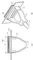
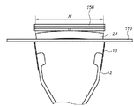
図5(A)は、本参考例に係るアクセサリ装置10の粘着部14の中央がLPF156に当接した時の要部上面図、図5(B)は、図5(A)の状態における要部斜視図である。   FIG. 5A is a top view of the main part when the center of the adhesive part 14 of the accessory device 10 according to this reference example is in contact with the LPF 156, and FIG. 5B is the main part in the state of FIG. FIG.

図5(A)に示すように、アクセサリ装置10の粘着部14の略中央部がLPF156の表面に当接した状態における、アクセサリ装置10の弾性部13の紙面横方向(カメラ10の撮像画面の横方向と同じ)の寸法をAとする。ここで図5(A)の状態からユーザがアクセサリ装置10を更にLPF156方向に押し込むと、その動作に応じて円弧状態の弾性部13の曲率半径が徐々に大きくなる。それに伴って粘着部14とLPF156とが当接する面積が拡大される。これにより、図6(A)に示すように、粘着部14の表面が平坦になって寸法B(B>A)まで拡大され、その粘着部14の略全域がLPF156と当接される。   As shown in FIG. 5A, the horizontal direction of the elastic portion 13 of the accessory device 10 in the state where the substantially central portion of the adhesive portion 14 of the accessory device 10 is in contact with the surface of the LPF 156 (on the imaging screen of the camera 10). A) is the same as the horizontal direction. Here, when the user further pushes the accessory device 10 in the LPF 156 direction from the state of FIG. 5A, the radius of curvature of the elastic portion 13 in the arc state gradually increases in accordance with the operation. Along with this, the area where the adhesive portion 14 and the LPF 156 abut is enlarged. As a result, as shown in FIG. 6A, the surface of the adhesive portion 14 becomes flat and is enlarged to a dimension B (B> A), and substantially the entire area of the adhesive portion 14 is brought into contact with the LPF 156.

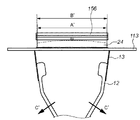
図6(A)は、図5(A)の状態からアクセサリ装置10を更にLPF156方向に押し込んで粘着部14の略全域がLPF156の表面に当接した状態を示す要部上面図で、この状態では、粘着部14がLPF156の表面形状にならってほぼ平坦になっている。図6(B)はその時の要部斜視図である。   6A is a top view of the main part showing a state in which the accessory device 10 is further pushed in the LPF 156 direction from the state of FIG. 5A and the substantially entire area of the adhesive portion 14 is in contact with the surface of the LPF 156. Then, the adhesive portion 14 is substantially flat following the surface shape of the LPF 156. FIG. 6B is a perspective view of a main part at that time.

図5(B)及び図6(B)に示すように、アクセサリ装置10はフォーカルプレンシャッタ113が開放状態になることにより形成される開口113aを介して粘着部14がLPF156と当接可能になっている。   As shown in FIGS. 5B and 6B, in the accessory device 10, the adhesive portion 14 can come into contact with the LPF 156 through an opening 113a formed when the focal plane shutter 113 is opened. ing.

尚、図6(A)における紙面横方向におけるAからBへの寸法拡大は、図5(A)の状態から、ユーザがアクセサリ装置10を更に押し込む動作に応じて、アクセサリ装置10の可撓部12が図6(A)に示した矢印C方向に撓んで広がることにより吸収される。上述の一連の動作により、アクセサリ装置10の粘着部14は、最初にその略中央部からLPF156に当接して、その押し込み動作に応じて、その当接する範囲が徐々にLPF156の周辺部へと広がるので、最終的にLPF156の表面に略均一に付着することになる。   Note that the dimension expansion from A to B in the horizontal direction of the paper surface in FIG. 6A is performed by the flexible portion of the accessory device 10 in accordance with the operation of the user further pushing the accessory device 10 from the state of FIG. 12 is absorbed by bending and spreading in the direction of arrow C shown in FIG. Through the series of operations described above, the adhesive portion 14 of the accessory device 10 first contacts the LPF 156 from its substantially central portion, and the contact range gradually expands to the peripheral portion of the LPF 156 according to the pushing operation. Therefore, it finally adheres to the surface of the LPF 156 substantially uniformly.

これとは逆に、図6(A)の状態からユーザが、アクセサリ装置10を引き離していくと、アクセサリ装置10の可撓部14の撓んだ状態から、徐々にその撓み量が減少する。それに伴い、弾性部13も図6(A)のほぼ平坦の形状から図5(A)に示す円弧状へと戻っていく。これにより粘着部14は、LPF156表面の周辺部から離れていき、最後に、粘着部14の略中央部がLPF156の中央部から離れてLPF156との当接状態が解除される。これにより、LPF156の表面に付着した塵埃は粘着部14に吸着されてLPF156の表面から除去される。そしてアクセサリ装置10がカメラ10のマウント機構101の開口を介してカメラ10の内部から外部に取り出されることにより、内部に付着していた塵埃はカメラ10の外部に完全に排出されることとなる。   On the contrary, when the user pulls away the accessory device 10 from the state of FIG. 6A, the amount of bending gradually decreases from the bent state of the flexible portion 14 of the accessory device 10. Accordingly, the elastic portion 13 also returns from the substantially flat shape in FIG. 6A to the arc shape shown in FIG. As a result, the adhesive portion 14 moves away from the peripheral portion of the LPF 156 surface, and finally, the substantially central portion of the adhesive portion 14 moves away from the central portion of the LPF 156 and the contact state with the LPF 156 is released. Thereby, the dust adhering to the surface of the LPF 156 is adsorbed by the adhesive portion 14 and removed from the surface of the LPF 156. Then, when the accessory device 10 is taken out from the inside of the camera 10 through the opening of the mount mechanism 101 of the camera 10, dust attached to the inside is completely discharged to the outside of the camera 10.

図7は、上述のようにしてアクセサリ装置10の粘着部14に付着させてカメラ10の外部に排出した塵埃を、粘着部14から剥離する方法の一例を説明する概略図である。   FIG. 7 is a schematic diagram for explaining an example of a method for separating the dust attached to the adhesive portion 14 of the accessory device 10 and discharged to the outside of the camera 10 from the adhesive portion 14 as described above.

図において、20は粘着部14よりも高い粘着力を有するシート状の転写材(例えば、尾高ゴム工業製「タッキー」)である。尚、この転写材20の形状及び構成はこれに限らず、例えばローラ形状をしたものでも同様の効果が得られる。また図7において、30はLPF156の表面に付着した塵埃(ゴミ)を示している。   In the figure, reference numeral 20 denotes a sheet-like transfer material (for example, “Tacky” manufactured by Odaka Rubber Industry) having an adhesive force higher than that of the adhesive portion 14. The shape and configuration of the transfer material 20 are not limited to this, and the same effect can be obtained even in a roller shape, for example. In FIG. 7, 30 indicates dust (dust) adhering to the surface of the LPF 156.

図7に示した状態から、アクセサリ装置10の粘着部14を転写材20に押し付けると、その転写材20は、粘着部14よりも高い粘着力を有しているため、その粘着部14に付着していた塵埃30は転写材20の表面に付着される。これにより、粘着部14の表面に付着していた塵埃が除去され粘着部14が清掃されて、ゴミなどが付着していない元の状態に戻される。   When the adhesive portion 14 of the accessory device 10 is pressed against the transfer material 20 from the state shown in FIG. 7, the transfer material 20 has a higher adhesive force than the adhesive portion 14, and therefore adheres to the adhesive portion 14. The dust 30 that has been deposited is attached to the surface of the transfer material 20. Thereby, the dust adhering to the surface of the adhesion part 14 is removed, the adhesion part 14 is cleaned, and it returns to the original state where dust etc. have not adhered.

尚、更に、転写材20の表面に付着した塵埃30を除去するには、その表面をアルコール系の溶剤や水で洗浄することにより行う。   Furthermore, in order to remove the dust 30 adhering to the surface of the transfer material 20, the surface is washed with an alcohol solvent or water.

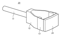
図8は、粘着部14を粘着ゴム24(例えば、角田ブラシ製「カーボレスMIMOZA-ST」)で構成した、本発明の参考例の変形例に係るアクセサリ装置20の外観斜視図である。尚、このアクセサリ装置20の他の構成(支持部11、可撓部12、弾性部13)は、前述の参考例のアクセサリ装置10と同じであるため同じ番号を符し、その説明を省略する。   FIG. 8 is an external perspective view of an accessory device 20 according to a modification of the reference example of the present invention in which the adhesive portion 14 is configured by an adhesive rubber 24 (for example, “Carboless MIMOZA-ST” manufactured by Kakuda Brush). In addition, since the other structure (the support part 11, the flexible part 12, and the elastic part 13) of this accessory apparatus 20 is the same as the accessory apparatus 10 of the above-mentioned reference example, it attaches | subjects the same number and abbreviate | omits the description. .

図9及び図10は、本発明の参考例の変形例に係るアクセサリ装置20がカメラ10のマウント機構101の開口からフォーカルプレンシャッタ113の開口113aを介してカメラ内部に侵入して、LPF156の表面に付着した塵埃を除去する時の要部上面図である。   9 and 10 show that the accessory device 20 according to a modification of the reference example of the present invention enters the camera through the opening 113a of the focal plane shutter 113 from the opening of the mounting mechanism 101 of the camera 10 and the surface of the LPF 156. It is a principal part top view at the time of removing the dust adhering to.

前述の図5及び図6を用いて説明したのと同様に、図9はアクセサリ装置20の粘着ゴム24の略中央がLPF156に当接した時の要部上面図を示している。また図10は、図9の状態から、アクセサリ装置20を更にLPF156方向に押し込んで粘着部14の略全域がLPF156の表面に当接し、粘着ゴム24がLPF156の表面形状にならってほぼ平坦になった状態を示す要部上面図である。   Similarly to the description with reference to FIGS. 5 and 6 described above, FIG. 9 shows a top view of the main part when the approximate center of the adhesive rubber 24 of the accessory device 20 contacts the LPF 156. Further, in FIG. 10, the accessory device 20 is further pushed in the direction of the LPF 156 from the state of FIG. It is a principal part top view which shows the state.

図9に示したように、アクセサリ装置20の粘着ゴム24の中央部が当接した状態で、アクセサリ装置20の弾性部13の紙面横方向(カメラ10の撮像画面の横方向と同じ)の寸法をA´とする。ここで図9の状態から、ユーザが更にアクセサリ装置20をLPF156方向に押し込むと、その動作に応じて円弧状態の弾性部13の曲率半径が徐々に大きくなる。これに伴って粘着ゴム24とLPF156とが当接する面積が広がっていく。これにより図9で示した寸法A'が徐々に長くなり、最後には図10で示したように、粘着ゴム24の略全域がLPF156と当接し、粘着ゴム24がほぼ平坦になった時には寸法B'(B'>A')まで長くなっている。   As shown in FIG. 9, the dimensions of the elastic part 13 of the accessory device 20 in the horizontal direction on the paper surface (same as the horizontal direction of the imaging screen of the camera 10) with the central portion of the adhesive rubber 24 of the accessory device 20 in contact. Is A ′. Here, when the user further pushes the accessory device 20 in the LPF 156 direction from the state of FIG. 9, the radius of curvature of the elastic portion 13 in the circular arc state gradually increases according to the operation. Along with this, the area where the adhesive rubber 24 and the LPF 156 contact each other increases. As a result, the dimension A ′ shown in FIG. 9 gradually increases, and finally, as shown in FIG. 10, the entire area of the adhesive rubber 24 comes into contact with the LPF 156, and the dimension when the adhesive rubber 24 becomes substantially flat. It is long until B ′ (B ′> A ′).

この紙面横方向の寸法拡大は、図9からユーザがアクセサリ装置20を押し込む動作に応じて、可撓部12が図10に示した矢印C'方向に撓んで広がることにより吸収される。上述の一連の動作により、アクセサリ装置20の粘着ゴム24は、最初にその略中央部がLPF156と当接し、押し込まれるのにつれて徐々にLPF156の周辺部へと当接していく。そして最後にはLPF156の表面に略均一に付着することになる。   This size expansion in the horizontal direction of the paper surface is absorbed by the flexible portion 12 being bent and expanded in the direction of the arrow C ′ shown in FIG. 10 according to the operation of the user pushing the accessory device 20 from FIG. Through the series of operations described above, the adhesive rubber 24 of the accessory device 20 first comes into contact with the LPF 156 at its substantially central portion, and gradually comes into contact with the peripheral portion of the LPF 156 as it is pushed. Finally, it adheres to the surface of the LPF 156 substantially uniformly.

これとは逆に、ユーザが図10の状態からアクセサリ装置20を引き離していくと、アクセサリ装置20の可撓部12の撓んだ状態から、徐々にその撓み量が減少する。それに伴い、弾性部13も、図10のほほ平坦の形状から図9の円弧状へと戻っていく。こうして粘着ゴム24は、LPF156表面の周辺部から離れていき、最後にはLPF156の略中央部から離れてLPF156との当接状態が解除される。   On the contrary, when the user pulls away the accessory device 20 from the state of FIG. 10, the amount of bending gradually decreases from the bent state of the flexible portion 12 of the accessory device 20. Accordingly, the elastic portion 13 also returns from the substantially flat shape of FIG. 10 to the arc shape of FIG. Thus, the adhesive rubber 24 moves away from the peripheral portion of the surface of the LPF 156, and finally leaves the substantially central portion of the LPF 156 to release the contact state with the LPF 156.

これにより、LPF156の表面に付着した塵埃は粘着ゴム24に吸着されて、LPF156の表面から除去される。そしてアクセサリ装置20がカメラ10の内部から取り出されることにより、LPF156やその近傍に付着していた塵埃は、カメラ10の外部に完全に排出されることとなる。   Thereby, dust adhering to the surface of the LPF 156 is adsorbed by the adhesive rubber 24 and removed from the surface of the LPF 156. Then, when the accessory device 20 is taken out from the inside of the camera 10, the dust attached to the LPF 156 and its vicinity is completely discharged to the outside of the camera 10.

尚、粘着ゴム24に付着した塵埃を除去する方法は、図7を参照して説明した方法と同でじでもよく、或はアルコール系の溶剤で洗浄しても構わない。   The method for removing dust adhering to the adhesive rubber 24 may be the same as the method described with reference to FIG. 7, or may be washed with an alcohol-based solvent.

なお、上述の実施例においては、図2を用いて、フォーカルプレーンシャッタ113より固体撮像素子106へ至る撮像光軸に沿ってLPF156、カバーガラス125が順に並んでおり、LPF156上にに付着した塵埃を除去することについて説明したが、光学部材の配置によっては必ずしもLPF156上の塵埃を除去することに限るものではなく、本質的には撮像に影響を与える塵埃を除去すべく、このような塵埃が付着する撮像光軸上の光学部材に対して粘着部を接触させるものである。   In the above-described embodiment, with reference to FIG. 2, the LPF 156 and the cover glass 125 are arranged in order along the imaging optical axis from the focal plane shutter 113 to the solid-state imaging device 106, and dust adhered on the LPF 156. However, depending on the arrangement of the optical member, it is not necessarily limited to removing dust on the LPF 156. Essentially, such dust is removed in order to remove dust that affects the imaging. The adhesive portion is brought into contact with the optical member on the imaging optical axis that adheres.

以上説明したように本参考例によれば、カメラの撮像部を構成する光学フィルタや保護レンズなどの表面に付着した単数もしくは複数の塵埃を、一度の作業で確実に除去できるアクセサリ装置を提供できる。   As described above, according to this reference example, it is possible to provide an accessory device that can reliably remove one or more dusts adhering to the surface of an optical filter, a protective lens, or the like constituting an imaging unit of a camera by a single operation. .

また本参考例に係るアクセサリ装置に付着した塵埃を簡単かつ確実に除去できるため、そのアクセサリ装置を繰り返し使用できるという効果がある。   In addition, dust attached to the accessory device according to this reference example can be easily and reliably removed, so that the accessory device can be used repeatedly.

前述の参考例では、ユーザがカメラ内を目視しながらアクセサリ装置10を使用してLPF156に付着した塵埃を除去する方法について説明したが、本実施の形態では、カメラのマウント機構101に取り付けられた状態で、LPF156に付着した塵埃を除去するアクセサリ装置の場合で説明する。   In the above-described reference example, the method for removing dust attached to the LPF 156 using the accessory device 10 while the user visually observes the inside of the camera has been described. However, in this embodiment, the accessory is attached to the camera mount mechanism 101. The case of an accessory device that removes dust adhering to the LPF 156 in the state will be described.

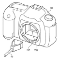
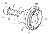
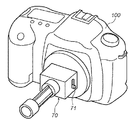
図11は、本発明の実施の形態に係るアクセサリ装置50の構成を示す斜視図で、クリーニングモードになっているカメラ100に取り付けられる状態を示している。   FIG. 11 is a perspective view showing the configuration of the accessory device 50 according to the embodiment of the present invention, and shows a state where the accessory device 50 is attached to the camera 100 in the cleaning mode.

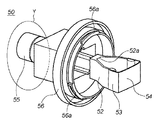
図12は、LPF156に付着した塵埃を除去するために、アクセサリ装置50の支持部55をユーザが押して粘着部54がカメラの内部方向に突出した状態を示した斜視図である。後述するが、図12の状態は、粘着部54の略全域がLPF156に当接して、その粘着部54の前面がほぼ平坦になった時(図6(A)で前述した状態に相当)のものである。   FIG. 12 is a perspective view illustrating a state in which the user presses the support portion 55 of the accessory device 50 to remove dust attached to the LPF 156 and the adhesive portion 54 protrudes toward the inside of the camera. As will be described later, the state of FIG. 12 is the case where substantially the entire area of the adhesive portion 54 is in contact with the LPF 156 and the front surface of the adhesive portion 54 is substantially flat (corresponding to the state described above with reference to FIG. 6A). Is.

図11及び図12において、軸部51は、粘着部54をカメラ100内のLPF156に密着させるために前方に移動させ、またLPF156から粘着部54を剥離するために退却させるための軸で、その外周には粘着部54が進退時に、マウント機構101に対して回転しないように複数の回転止め部51aを備えている。尚、この回転止め部51aは、回転を防止できれば少なくとも一つあれば良い。可撓部52、弾性部53、粘着部54はいずれも、前述の実施の形態に係る可撓部12、弾性部13、粘着部14のそれぞれと同じ動作及び機能を有しているので、その説明を省略する。   11 and 12, the shaft portion 51 is a shaft for moving the adhesive portion 54 forward to closely contact the LPF 156 in the camera 100 and for retracting the adhesive portion 54 from the LPF 156. A plurality of anti-rotation portions 51a are provided on the outer periphery so that the adhesive portion 54 does not rotate relative to the mount mechanism 101 when the adhesive portion 54 advances and retreats. It should be noted that at least one anti-rotation portion 51a is sufficient if rotation can be prevented. The flexible part 52, the elastic part 53, and the adhesive part 54 all have the same operations and functions as the flexible part 12, the elastic part 13, and the adhesive part 14 according to the above-described embodiment. Description is omitted.

支持部55は、ユーザが、このアクセサリ装置50を操作させる際にユーザが操作するために使用される。取り付け部56は、このアクセサリ装置50をカメラ100のマウント機構101に取り付けるための機構部である。この取り付け部56には、マウント機構101に位置決めされて係止する複数の係止部56aと、後述するように、軸部51に設けられた回転止め部51aと摺動可能な嵌合部56c(図17、図18)が設けられている。   The support portion 55 is used by the user to operate the accessory device 50 when the user operates the accessory device 50. The attachment unit 56 is a mechanism unit for attaching the accessory device 50 to the mount mechanism 101 of the camera 100. The mounting portion 56 includes a plurality of locking portions 56a that are positioned and locked by the mount mechanism 101, and a fitting portion 56c that can slide with a rotation stopping portion 51a provided on the shaft portion 51, as will be described later. (FIGS. 17 and 18) are provided.

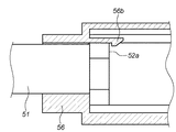
また、取り付け部56は、アクセサリ装置50がカメラ100のマウント機構101に取り付けた状態で操作する前に、カメラ100がクリーニングモードであるかどうかを確認できるように、その全てが透明か、もしくは図13に示すように、その一部に外部からカメラ100内部が観察可能な窓56dが設けられている方が望ましい。これにより、ユーザは、アクセサリ装置50を操作する前に、カメラ100のハーフミラー111が図2の破線で示した第2の光路分割状態の位置111aに配設されているか否かが確認できるので、故障等の不具合でカメラ100をクリーニングモードにしたにも係らず、ハーフミラー111が第2の光路分割状態の位置111aに配設されていない状態になってしまっても、アクセサリ装置50の操作を中止する事が容易に出来るから、アクセサリ装置50を用いたLPF156に付着した塵埃の除去作業を安全に行う事が出来る。   In addition, before the operation of the attachment unit 56 with the accessory device 50 attached to the mount mechanism 101 of the camera 100, all of the attachment unit 56 is transparent or can be checked so that the camera 100 is in the cleaning mode. As shown in FIG. 13, it is desirable that a window 56d that allows the inside of the camera 100 to be observed from the outside is provided in a part thereof. Thereby, the user can confirm whether or not the half mirror 111 of the camera 100 is disposed at the position 111a in the second optical path division state indicated by the broken line in FIG. 2 before operating the accessory device 50. Even if the camera 100 is set to the cleaning mode due to a malfunction or the like, the operation of the accessory device 50 is performed even if the half mirror 111 is not disposed at the position 111a in the second optical path division state. Therefore, it is possible to safely remove the dust attached to the LPF 156 using the accessory device 50.

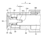
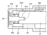
図14は、図11のXで示すように、軸部51の長さ方向に平行な面で切断した断面図であり、図15は図12のYで示すように、軸部51の長さ方向に平行な面で切断した断面図である。   14 is a cross-sectional view taken along a plane parallel to the length direction of the shaft portion 51 as indicated by X in FIG. 11, and FIG. 15 is the length of the shaft portion 51 as indicated by Y in FIG. It is sectional drawing cut | disconnected by the surface parallel to a direction.

図14において、略V字形状の可撓部52に設けられた平坦部52aは、取り付け部56に設けられた弾性変形可能な係止部56bにより係止される。これにより、アクセサリ装置50がカメラ100に取り付けられた直後には、アクセサリ装置50がカメラの内部方向に移動しないようにロックしている。尚、アクセサリ装置50がカメラ100に取り付けられた後、ユーザが支持部55を押して軸部51を図11の状態から図12に示すように、カメラ内に押し込んだ時には、平坦部52aが係止部56bを乗り越えることができる。その際、係止部56bは図15に示すように、上方向に弾性変形している。   In FIG. 14, the flat portion 52 a provided in the substantially V-shaped flexible portion 52 is locked by an elastically deformable locking portion 56 b provided in the attachment portion 56. Thus, immediately after the accessory device 50 is attached to the camera 100, the accessory device 50 is locked so as not to move in the internal direction of the camera. After the accessory device 50 is attached to the camera 100, when the user pushes the support portion 55 and pushes the shaft portion 51 into the camera as shown in FIG. 12, the flat portion 52a is locked. The part 56b can be overcome. At that time, the locking portion 56b is elastically deformed upward as shown in FIG.

図15において、段ビス57は、ネジ部57aと軸部57bとを具備している。ネジ部57aは、軸部51に設けられたメネジ部51bとネジ締結されており、これにより軸部51と支持部55とが一体化されている。また軸部57bは支持部55に設けられた嵌合穴55aと摺動可能に嵌合している。弾性部材58は、支持部55と軸部51との間に設けられているゴムなどの弾性体である。その作用については後述する。キャップ59は、段ビス57が外部から見えないように支持部55に設けられている。   In FIG. 15, the step screw 57 includes a screw portion 57a and a shaft portion 57b. The screw portion 57a is screwed to a female screw portion 51b provided on the shaft portion 51, whereby the shaft portion 51 and the support portion 55 are integrated. The shaft portion 57b is slidably fitted in a fitting hole 55a provided in the support portion 55. The elastic member 58 is an elastic body such as rubber provided between the support portion 55 and the shaft portion 51. Its operation will be described later. The cap 59 is provided on the support portion 55 so that the stepped screw 57 cannot be seen from the outside.

図15に示したように、粘着部54の略全域がLPF156に当接した状態(図6(A))であっても、支持部55と取り付け部56との間には一定量のギャップLが形成されている。   As shown in FIG. 15, even when substantially the entire area of the adhesive portion 54 is in contact with the LPF 156 (FIG. 6A), there is a certain amount of gap L between the support portion 55 and the attachment portion 56. Is formed.

ここで図15に示した状態からユーザがなおも支持部55を同図の矢印Z方向に押し込み続けた場合について説明する。このとき、単に支持部55と軸部51とが一体で形成されていると、ユーザがZ方向に押し込む力がそのまま粘着部54を介してLPF156に加わってしまう。これによりLPF156の位置が動いてピントずれの不具合を生じる可能性がある。   Here, a case will be described in which the user continues to push the support portion 55 in the arrow Z direction in FIG. 15 from the state shown in FIG. At this time, if the support part 55 and the shaft part 51 are simply formed integrally, the force that the user pushes in the Z direction is applied to the LPF 156 as it is through the adhesive part 54. As a result, the position of the LPF 156 may move and cause a problem of defocusing.

しかしながら本実施の形態に係る構成の場合、図15の状態から、ユーザが更に支持部55をZ方向に押し込むと、支持部55の嵌合穴55aと段ビス57の軸部57bとが摺動して支持部55のみが図16に示すように矢印Z方向に移動する。これにより、弾性部材58が圧縮されて、図15に示す支持部55と取り付け部56との間のギャップLが無くなって吸収される。このギャップLは、図6(A)の状態から更に軸部51が押し込まれても、可撓部材52(12)や弾性体53(13)の撓みで吸収できる程度の長さに設定されている。この状態での弾性部材58の反発力は、ユーザが押し込むZ方向の力と逆方向に作用するので、この反発力によりユーザが押し込む力が打ち消される。また図16に示したようにギャップLが無くなった状態では、支持部55のZ方向への移動は、取り付け部56との係合面1500により規定されるため、ユーザが無理にこれ以上押し込もうとしても軸部51がこれ以上カメラ内に進入することはない。こうして、LPF156に加わる力が減少されてLPF156が保護される。従って、粘着部54の略全域がLPF156に当接している状態(図15)から、更にユーザが支持部55を押し込もうとしても図16の状態で示す以上に押し込まれることがないため、粘着部54がLPF156を押してLPF156の位置が動いてピントずれになる恐れがない。   However, in the case of the configuration according to the present embodiment, when the user further pushes the support portion 55 in the Z direction from the state of FIG. 15, the fitting hole 55a of the support portion 55 and the shaft portion 57b of the step screw 57 slide. Only the support portion 55 moves in the arrow Z direction as shown in FIG. Thereby, the elastic member 58 is compressed and the gap L between the support part 55 and the attachment part 56 shown in FIG. The gap L is set to a length that can be absorbed by the bending of the flexible member 52 (12) or the elastic body 53 (13) even if the shaft 51 is further pushed in from the state of FIG. Yes. In this state, the repulsive force of the elastic member 58 acts in the opposite direction to the force in the Z direction that the user pushes in. Therefore, the force pushed in by the user is canceled out by this repulsive force. Also, as shown in FIG. 16, in the state where the gap L is eliminated, the movement of the support portion 55 in the Z direction is defined by the engagement surface 1500 with the attachment portion 56, so that the user forcibly pushes it further. The shaft portion 51 will not enter the camera any more. Thus, the force applied to the LPF 156 is reduced and the LPF 156 is protected. Accordingly, since the substantially entire region of the adhesive portion 54 is in contact with the LPF 156 (FIG. 15), even if the user tries to push the support portion 55 further, it is not pushed more than shown in the state of FIG. There is no possibility that the portion 54 presses the LPF 156 and the position of the LPF 156 moves to cause a focus shift.

図17〜図19は、本実施の形態に係るアクセサリ装置50をクリーニングモードになっているカメラ100に取り付けて動作させる際の状態を説明する斜視図である。   17 to 19 are perspective views for explaining a state when the accessory device 50 according to the present embodiment is attached to the camera 100 in the cleaning mode and operated.

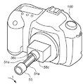
図17は、このアクセサリ装置50をカメラ100に取り付ける直前の状態を示す概観斜視図であり、この時、粘着部54や支持部50は図11に示した状態である。   FIG. 17 is a schematic perspective view showing a state immediately before the accessory device 50 is attached to the camera 100. At this time, the adhesive portion 54 and the support portion 50 are in the state shown in FIG.

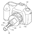
図18は、図17の状態からアクセサリ装置50をカメラ100のマウント機構101に装着して、同図中矢印T方向に回転させて取り付けた状態を示す。これによりアクセサリ装置50の係止部56aがカメラ100のマウント機構101に対して位置決めされて完全に固定される。この状態でも、アクセサリ装置50は図11に示した状態となっている。   FIG. 18 shows a state in which the accessory device 50 is attached to the mount mechanism 101 of the camera 100 from the state of FIG. 17 and rotated in the direction of arrow T in FIG. As a result, the locking portion 56a of the accessory device 50 is positioned with respect to the mount mechanism 101 of the camera 100 and is completely fixed. Even in this state, the accessory device 50 is in the state shown in FIG.

ここで上述したように、軸部51は嵌合部56cと嵌合して取り付け部56に対して回動しないように構成されている。これにより粘着部54は、このアクセサリ装置50がカメラ本体に取り付けられる際、そのアクセサリ装置50と同じ回転角で保持される。従って、上述の図18に示すように、アクセサリ装置50が矢印T方向に回転させて取り付けられた状態で、粘着部54がフォーカルプレンシャッタ113の開口113aにちょうど位置付けられるように、アクセサリ装置50に対する粘着部54の取り付け方向が規定されている。   As described above, the shaft portion 51 is configured to be fitted to the fitting portion 56 c so as not to rotate with respect to the attachment portion 56. Thereby, the adhesive portion 54 is held at the same rotation angle as that of the accessory device 50 when the accessory device 50 is attached to the camera body. Accordingly, as shown in FIG. 18 described above, with respect to the accessory device 50 such that the adhesive portion 54 is positioned exactly at the opening 113a of the focal plane shutter 113 with the accessory device 50 rotated and attached in the arrow T direction. The attachment direction of the adhesion part 54 is prescribed | regulated.

この状態からユーザがLPF156に付着した塵埃を除去するために支持部55をカメラ100の内部に向けて押し込むと、軸部51に設けられた回転止め部51aと取り付け部56に設けられた嵌合部56cとが嵌合状態を保持したまま軸部51の軸方向に摺動して、カメラ100内に粘着部54が侵入する。これにより、この押し込む際に、粘着部54がカメラ100内で回動したり、その内部の構造に触れる虞はない。よって、図6(B)で示したように、粘着部54は正確にフォーカルプレンシャッタ113の開口113aを通ってLPF156と当接する。   When the user pushes the support portion 55 toward the inside of the camera 100 in order to remove dust attached to the LPF 156 from this state, the rotation stop portion 51a provided on the shaft portion 51 and the fitting provided on the attachment portion 56 The adhesive portion 54 enters the camera 100 by sliding in the axial direction of the shaft portion 51 while maintaining the fitted state with the portion 56c. As a result, there is no possibility that the adhesive portion 54 rotates in the camera 100 or touches the internal structure during the pushing. Therefore, as shown in FIG. 6B, the adhesive portion 54 accurately contacts the LPF 156 through the opening 113a of the focal plane shutter 113.

図19は、図18の状態から更にユーザが支持部55を矢印1800の方向に押し込んで、粘着部54の略全域がLPF156と当接した状態を示す概観斜視図である。   FIG. 19 is a schematic perspective view showing a state in which the user further pushes the support portion 55 in the direction of the arrow 1800 from the state of FIG. 18 so that substantially the entire area of the adhesive portion 54 is in contact with the LPF 156.

図15を参照して説明したように、図19の状態では、弾性部材58の反作用により支持部55と取り付け部56との間にはギャップLが形成されているので、図19の状態からユーザが支持部55を矢印1800の方向に更に押し込んでも、弾性部材58がその力を吸収してLPF156が保護される。更に、図16のような状態になっても、支持部55の進入が取り付け部56との係合面1500により規定されるので、その押し込む力がLPF156に作用してLPF156の位置がずれることはない。   As described with reference to FIG. 15, in the state of FIG. 19, the gap L is formed between the support portion 55 and the attachment portion 56 due to the reaction of the elastic member 58. Even if the support portion 55 is further pushed in the direction of the arrow 1800, the elastic member 58 absorbs the force and the LPF 156 is protected. Further, even when the state shown in FIG. 16 is reached, the entry of the support portion 55 is defined by the engagement surface 1500 with the attachment portion 56, so that the pushing force acts on the LPF 156 and the position of the LPF 156 is shifted. Absent.

以上説明したように本実施の形態によれば、撮像素子近傍の光学フィルタ表面に付着した単数もしくは複数の塵埃が一度のクリーニング作業で除去できるアクセサリ装置を提供できる。   As described above, according to the present embodiment, it is possible to provide an accessory device that can remove one or more dusts adhering to the surface of the optical filter in the vicinity of the image sensor by a single cleaning operation.

また、アクセサリ装置の粘着部に付着した塵埃を、簡単かつ確実に除去できる清掃手段を提供できる。   Moreover, the cleaning means which can remove easily and reliably the dust adhering to the adhesion part of an accessory apparatus can be provided.

更に、アクセサリ装置の粘着部が、カメラに対して位置決めされた状態で、カメラ内部の構造に触れること無く侵入させることができるので、光学フィルタ表面に付着した塵埃を除去する際に光学機器内部を汚染したリ、損傷を与える虞がない。   Furthermore, since the adhesive part of the accessory device can be inserted without touching the structure inside the camera while being positioned with respect to the camera, the inside of the optical device can be removed when removing dust adhering to the surface of the optical filter. There is no risk of contamination or damage.

ところで、上述の実施の形態,2では、このような清掃に使用する装置をアクセサリ装置として説明してきたが、例えば図20に示すように、アクセサリ装置50がカメラ100のボディキャップ70として機能するものでも良い。   
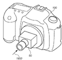
By the way, in the above-mentioned embodiment and 2, the apparatus used for such cleaning has been described as an accessory apparatus. However, as shown in FIG. 20, for example, the accessory apparatus 50 functions as a body cap 70 of the camera 100. But it ’s okay.

このボディキャップ70は、カメラ100のマウント機構101との公知の通信手段(不図示)と、その通信手段によりカメラ100をクリーニングモードに設定できるスイッチ71を備える。そのスイッチ71がオフの時には通常のボディキャップとして使用し、スイッチ71がオンされた時には、公知の通信手段を介してカメラ100をクリーニングモードにする。その後、ユーザが手動にて支持部55を操作して、前述の実施の形態で説明したようにLPF156に付着した塵埃を除去する。このような構成においても、前述の実施の形態と同様の効果が得られる。   The body cap 70 includes a known communication means (not shown) with the mount mechanism 101 of the camera 100 and a switch 71 that can set the camera 100 to the cleaning mode by the communication means. When the switch 71 is off, it is used as a normal body cap, and when the switch 71 is on, the camera 100 is put into a cleaning mode via a known communication means. Thereafter, the user manually operates the support portion 55 to remove dust attached to the LPF 156 as described in the above-described embodiment. Even in such a configuration, the same effects as those of the above-described embodiment can be obtained.

更に、このボディキャップ70に、前述の軸部51や粘着部54をカメラ100に対して進退させるモータ等の駆動手段を備えることによって、スイッチ71をオンすることにより、カメラ100をクリーニングモードにして自動的に粘着部54をカメラ100内に移動させて、LPF156の表面に付着した塵埃を除去するように構成しても良い。   Further, the body cap 70 is provided with driving means such as a motor for moving the shaft portion 51 and the adhesive portion 54 back and forth with respect to the camera 100, and by turning on the switch 71, the camera 100 is brought into the cleaning mode. The adhesive unit 54 may be automatically moved into the camera 100 to remove dust attached to the surface of the LPF 156.

また前述の実施の形態では、実施の形態の支持部11に相当する部分が、操作部555と軸部51で構成されているが、図1の構成に図11に示す取り付け部56が付加された構成でも良い。但し、この場合には、実施の形態における操作部55と取り付け部56との間のギャップL、弾性部材58に代わる、アクセサリ装置の所定量以上の進入を防ぐための機構が必要になる。これには例えば、図6(A)に示すような状態で粘着部54とフィルタ面とが当接した状態で、略V字形状の可撓部52に設けられた平坦部52a(図12)と係合する取り付け部56の突起(不図示)を設け、それ以上奥に粘着部54が侵入するのを防止するようにしても良い。   In the above-described embodiment, the portion corresponding to the support portion 11 of the embodiment is configured by the operation portion 555 and the shaft portion 51. However, the attachment portion 56 shown in FIG. 11 is added to the configuration of FIG. A configuration may be used. However, in this case, a mechanism for preventing the accessory device from entering a predetermined amount or more is required instead of the gap L between the operation portion 55 and the attachment portion 56 and the elastic member 58 in the embodiment. For example, a flat portion 52a (FIG. 12) provided in the substantially V-shaped flexible portion 52 in a state where the adhesive portion 54 and the filter surface are in contact with each other in the state shown in FIG. A protrusion (not shown) of the attachment portion 56 that engages with the adhesive portion 54 may be provided so as to prevent the adhesive portion 54 from entering further behind.

尚、上述の実施の形態では、光学フィルタ面に付着した塵埃の除去方法について説明してきたが本発明はこれに限定されるものではなく、例えばフォーカルプレンシャッタの開口を介して固体撮像素子のカバーガラス表面が目視できるようなデジタルカラーカメラの場合は、その固体撮像素子のカバーガラスに付着した塵埃を本実施の形態に係るアクセサリ装置やボディキャップで除去できることは言うまでもない。   In the above-described embodiment, the method for removing dust adhering to the optical filter surface has been described. However, the present invention is not limited to this, and for example, the cover of the solid-state image sensor via the opening of the focal plane shutter. In the case of a digital color camera in which the glass surface can be visually observed, it goes without saying that dust adhering to the cover glass of the solid-state imaging device can be removed by the accessory device or the body cap according to this embodiment.

本発明の参考例に係るアクセサリ装置の構成を示す概観斜視図である。It is a general | schematic perspective view which shows the structure of the accessory apparatus which concerns on the reference example of this invention. 本実施の形態に係るアクセサリ装置を用いて塵埃を除去する対象機器である光学機器の一例であるデジタルカラーカメラの構成を説明するための側方視断面図である。It is a side view sectional view for demonstrating the structure of the digital color camera which is an example of the optical apparatus which is an object apparatus which removes dust using the accessory apparatus which concerns on this Embodiment. 本参考例に係るカメラの電気的構成を示すブロック図である。It is a block diagram which shows the electric constitution of the camera which concerns on this reference example. カメラがクリーニングモードになっている状態で、アクセサリ装置を使用してLPFの表面に付着した塵埃を除去する場合を説明する概略斜視図である。It is a schematic perspective view explaining the case where the dust adhering to the surface of LPF is removed using an accessory device in the state where the camera is in the cleaning mode. 本参考例に係るアクセサリ装置の粘着部の中央がLPFに当接した時の要部上面図(A)と図5(A)の状態における要部斜視図(B)である。FIGS. 6A and 6B are a top view of the main part when the center of the adhesive part of the accessory device according to this reference example is in contact with the LPF and a perspective view of the main part in the state of FIG. 図5(A)の状態からアクセサリ装置を更にLPF方向に押し込んで粘着部の略全域がLPFの表面に当接した状態を示す要部上面図(A)とその時の要部斜視図(B)である。The main part top view (A) and the main part perspective view (B) showing the state where the accessory device is further pushed in the LPF direction from the state of FIG. It is. 本発明の参考例におけるアクセサリ装置の粘着部に付着した塵埃を除去する方法の一例を示した概略図である。It is the schematic which showed an example of the method of removing the dust adhering to the adhesion part of the accessory apparatus in the reference example of this invention. 本発明の参考例の変形例に係るアクセサリ装置の外観斜視図である。It is an external appearance perspective view of the accessory apparatus which concerns on the modification of the reference example of this invention. 本発明の参考例の変形例に係るアクセサリ装置がLPFの表面に付着した塵埃を除去する時に、粘着部とLPFとが当接した状態を示す要部上面図である。It is a principal part top view which shows the state which the adhesion part and LPF contact | abutted when the accessory apparatus which concerns on the modification of the reference example of this invention removes the dust adhering to the surface of LPF. 本発明の参考例の変形例に係るアクセサリ装置がLPFの表面に付着した塵埃を除去する時に、粘着部がLPFに押し付けられた状態を示す要部上面図である。It is a principal part top view which shows the state by which the adhesion part was pressed on LPF when the accessory apparatus which concerns on the modification of the reference example of this invention removes the dust adhering to the surface of LPF. 本発明の実施の形態に係るアクセサリ装置の構成を示す斜視図である。It is a perspective view which shows the structure of the accessory apparatus which concerns on embodiment of this invention. 本発明の実施の形態に係るアクセサリ装置の構成を示す図で、塵埃を除去するためにアクセサリ装置の支持部を押して粘着部がカメラの内部方向に突出した状態を示した斜視図である。It is a figure which shows the structure of the accessory apparatus which concerns on embodiment of this invention, and is the perspective view which showed the state which pushed the support part of the accessory apparatus in order to remove dust, and the adhesion part protruded in the internal direction of the camera. 本発明の実施の形態に係るアクセサリ装置の構成を示す図で、その取り付け部の一部に窓が設けられた場合の状態を示した斜視図である。It is a figure which shows the structure of the accessory apparatus which concerns on embodiment of this invention, and is the perspective view which showed the state when a window is provided in a part of the attachment part. 図11のXで示す軸部の長さ方向に平行な面で切断した断面図である。It is sectional drawing cut | disconnected by the surface parallel to the length direction of the axial part shown by X of FIG. 図12のYで示す軸部の長さ方向に平行な面で切断した断面図である。It is sectional drawing cut | disconnected by the surface parallel to the length direction of the axial part shown by Y of FIG. 図14の状態から更に、アクセサリ装置を押し込んだ状態を示す断面図である。It is sectional drawing which shows the state which pushed in the accessory apparatus further from the state of FIG. 本発明の実施の形態に係るアクセサリ装置をカメラに取り付ける直前の状態を示す概観斜視図である。It is a general | schematic perspective view which shows the state just before attaching the accessory apparatus which concerns on embodiment of this invention to a camera. 図16の状態からアクセサリ装置をカメラのマウント機構に装着して、矢印T方向に回転させて取り付けた状態を示す斜視図である。It is a perspective view which shows the state which attached the accessory apparatus to the mount mechanism of the camera from the state of FIG. 16, and rotated and attached to the arrow T direction. 図17の状態から更にユーザが支持部を押し込んで、粘着部の略全域がLPFと当接した状態を示す概観斜視図である。FIG. 18 is a schematic perspective view showing a state in which the user further presses the support portion from the state of FIG. 本発明の実施の形態の変形例に係るアクセサリ装置をカメラに取り付けた状態を示す斜視図である。It is a perspective view which shows the state which attached the accessory apparatus which concerns on the modification of embodiment of this invention to the camera.

Claims (10)

光学機器に取り付けられ、当該光学機器が有する光学部材の表面及び/或はその近傍に付着した異物を除去するアクセサリ装置であって、
ユーザにより支持・操作される操作部と、
前記操作部と一体的に形成され略V字型を有する可撓部と、
前記可撓部に懸架された弾性部と、
前記弾性部の少なくとも先端部側に設けられた粘着部と、
前記光学機器のマウント機構と係合して当該アクセサリ装置を前記光学機器に取り付けるための取り付け機構とを有し、
前記取り付け機構により当該アクセサリ装置を前記光学機器に取り付けた状態で前記操作部が操作されることにより前記粘着部が前記光学機器内に進入して異物を除去することを特徴とするアクセサリ装置。
An accessory device that is attached to an optical device and removes foreign matter adhering to and / or near the surface of an optical member of the optical device,
An operation unit supported and operated by a user;
A flexible part integrally formed with the operation part and having a substantially V-shape;
An elastic part suspended from the flexible part;
An adhesive portion provided on at least the tip side of the elastic portion;
An attachment mechanism for engaging with the mount mechanism of the optical device and attaching the accessory device to the optical device;
The accessory device according to claim 1, wherein when the operation unit is operated in a state where the accessory device is attached to the optical device by the attachment mechanism, the adhesive portion enters the optical device to remove foreign matter.
光学機器に取り付けられ、当該光学機器が有する光学部材の表面及び/或はその近傍に付着した異物を除去するアクセサリ装置であって、
軸部の端部に設けられユーザにより操作される操作部と、
前記操作部と反対側の前記軸部の端部に設けられ略V字型を有する可撓部と、
前記可撓部に懸架された弾性部と、
前記弾性部の少なくとも先端部側に設けられた粘着部と、
前記光学機器のマウント機構と係合して当該アクセサリ装置を前記光学機器に取り付けるための取り付け機構とを有し、
前記取り付け機構により当該アクセサリ装置を前記光学機器に取り付けた状態で前記操作部が操作されることにより前記粘着部が前記光学機器内に進入して異物を除去することを特徴とするアクセサリ装置。
An accessory device that is attached to an optical device and removes foreign matter adhering to and / or near the surface of an optical member of the optical device,
An operation unit provided at an end of the shaft unit and operated by a user;
A flexible portion provided at the end of the shaft portion opposite to the operation portion and having a substantially V-shape;
An elastic part suspended from the flexible part;
An adhesive portion provided on at least the tip side of the elastic portion;
An attachment mechanism for engaging with the mount mechanism of the optical device and attaching the accessory device to the optical device;
The accessory device according to claim 1, wherein when the operation unit is operated in a state where the accessory device is attached to the optical device by the attachment mechanism, the adhesive portion enters the optical device to remove foreign matter.
光学機器に取り付けられ、当該光学機器が有する光学部材の表面及び/或はその近傍に付着した異物を除去するアクセサリ装置であって、
ユーザにより支持・操作される操作部と、
粘着面を具備する粘着部と、
可撓性を有し、前記操作部に対して前記粘着面を略直交するように展開して保持する可撓部と、
前記光学機器のマウント機構と係合して当該アクセサリ装置を前記光学機器に取り付けるための取り付け機構とを有し、
前記取り付け機構により当該アクセサリ装置を前記光学機器に取り付けた状態で前記操作部が操作されることにより前記粘着部が前記光学機器内に進入して異物を除去することを特徴とするアクセサリ装置。
An accessory device that is attached to an optical device and removes foreign matter adhering to and / or near the surface of an optical member of the optical device,
An operation unit supported and operated by a user;
An adhesive part having an adhesive surface;
A flexible portion that has flexibility and that expands and holds the adhesive surface so as to be substantially orthogonal to the operation portion;
An attachment mechanism for engaging with the mount mechanism of the optical device and attaching the accessory device to the optical device;
The accessory device according to claim 1, wherein when the operation unit is operated in a state where the accessory device is attached to the optical device by the attachment mechanism, the adhesive portion enters the optical device to remove foreign matter.
光学機器に取り付けられ、当該光学機器が有する光学部材の表面及び/或はその近傍に付着した異物を除去するアクセサリ装置であって、
軸部の端部に設けられユーザにより操作される操作部と、
粘着面を具備する粘着部と、
可撓制を有し、前記軸部と前記粘着面が略直交するように接続して保持する可撓部と、
前記光学機器のマウント機構と係合して当該アクセサリ装置を前記光学機器に取り付けるための取り付け機構とを有し、
前記取り付け機構により当該アクセサリ装置を前記光学機器に取り付けた状態で前記操作部が操作されることにより前記粘着部が前記光学機器内に進入して異物を除去することを特徴とするアクセサリ装置。
An accessory device that is attached to an optical device and removes foreign matter adhering to and / or near the surface of an optical member of the optical device,
An operation unit provided at an end of the shaft unit and operated by a user;
An adhesive part having an adhesive surface;
A flexible portion having a flexible system and connected and held so that the shaft portion and the adhesive surface are substantially orthogonal;
An attachment mechanism for engaging with the mount mechanism of the optical device and attaching the accessory device to the optical device;
The accessory device is characterized in that when the operation unit is operated in a state where the accessory device is attached to the optical device by the attachment mechanism, the adhesive portion enters the optical device and removes foreign matter.
前記取り付け機構と前記軸部との相対回転位置を規定する嵌合部材とを更に有することを特徴とする請求項1乃至4のいずれか1項に記載のアクセサリ装置。   The accessory device according to any one of claims 1 to 4, further comprising a fitting member that defines a relative rotational position between the attachment mechanism and the shaft portion. 前記取り付け機構は、前記アクセサリ装置と前記光学機器とを相対的に所定量回動させて取り付けるもので、前記取り付け機構により取り付けた後、前記粘着部が光学部材の表面及び/或はその近傍を含む清掃対称面に対して正対するように前記嵌合部材により前記相対回転位置が規定されていることを特徴とする請求項1乃至5のいずれか1項に記載のアクセサリ装置。   The attachment mechanism is configured to relatively rotate the accessory device and the optical device by a predetermined amount. After the attachment device is attached by the attachment mechanism, the adhesive portion is attached to the surface of the optical member and / or the vicinity thereof. The accessory device according to any one of claims 1 to 5, wherein the relative rotational position is defined by the fitting member so as to face a cleaning symmetry plane including the cleaning symmetrical surface. 前記操作部と前記軸部との間に弾性部材が設けられていることを特徴とする請求項1又は2に記載のアクセサリ装置。   The accessory device according to claim 1, wherein an elastic member is provided between the operation portion and the shaft portion. 前記粘着部の略全域が前記光学部材の表面に当接した状態で、前記操作部と前記取り付け機構との間に隙間が設けられていることを特徴とする請求項1乃至7のいずれか1項に記載のアクセサリ装置。   The gap is provided between the operation unit and the attachment mechanism in a state where substantially the entire area of the adhesive portion is in contact with the surface of the optical member. The accessory device according to item. 前記取り付け機構は前記光学機器との通信手段を備え、前記通信手段を介して前記光学機器を異物を除去するモードに設定するためのスイッチを更に有することを特徴とする請求項1乃至8のいずれか1項に記載のアクセサリ装置。   The said attachment mechanism is provided with a communication means with the said optical apparatus, and further has a switch for setting the said optical apparatus to the mode which removes a foreign material via the said communication means. The accessory device according to claim 1. 前記取り付け機構の少なくとも一部が透明である事を特徴とする請求項1乃至9のいずれか1項に記載のアクセサリ装置。   The accessory device according to any one of claims 1 to 9, wherein at least a part of the attachment mechanism is transparent.
JP2004106247A 2004-03-31 2004-03-31 Accessory device Withdrawn JP2005292404A (en)

Priority Applications (1)

Application Number Priority Date Filing Date Title
JP2004106247A JP2005292404A (en) 2004-03-31 2004-03-31 Accessory device

Applications Claiming Priority (1)

Application Number Priority Date Filing Date Title
JP2004106247A JP2005292404A (en) 2004-03-31 2004-03-31 Accessory device

Publications (1)

Publication Number Publication Date
JP2005292404A true JP2005292404A (en) 2005-10-20

Family

ID=35325400

Family Applications (1)

Application Number Title Priority Date Filing Date
JP2004106247A Withdrawn JP2005292404A (en) 2004-03-31 2004-03-31 Accessory device

Country Status (1)

Country Link
JP (1) JP2005292404A (en)

Cited By (19)

* Cited by examiner, † Cited by third party
Publication number Priority date Publication date Assignee Title
JP2007306390A (en) * 2006-05-12 2007-11-22 Pentax Corp Cleaning tool for imaging element
JP2008018142A (en) * 2006-07-14 2008-01-31 Pentax Service Co Ltd Cleaning implement for photographing device
JP2008018182A (en) * 2006-07-14 2008-01-31 Pentax Corp Cleaner for image pickup device
JP2008209628A (en) * 2007-02-26 2008-09-11 Sony Corp Carrying case for imaging apparatus
JP2009544373A (en) * 2006-07-28 2009-12-17 ノバダック テクノロジーズ インコーポレイテッド System and method for depositing and removing optical members at the objective of an endoscope
US8041208B2 (en) 2007-12-27 2011-10-18 Canon Kabushiki Kaisha Imaging apparatus having foreign substance removal member which overlaps shutter blade moving locus in optical axis direction
US8059194B2 (en) * 2008-09-22 2011-11-15 Parkside Optical Inc. Image sensor inspection and cleaning device
US9642532B2 (en) 2008-03-18 2017-05-09 Novadaq Technologies Inc. Imaging system for combined full-color reflectance and near-infrared imaging
US9814378B2 (en) 2011-03-08 2017-11-14 Novadaq Technologies Inc. Full spectrum LED illuminator having a mechanical enclosure and heatsink
US9877654B2 (en) 2006-02-07 2018-01-30 Novadaq Technologies Inc. Near infrared imaging
US9968244B2 (en) 2000-07-14 2018-05-15 Novadaq Technologies ULC Compact fluorescence endoscopy video system
US10182709B2 (en) 2002-01-15 2019-01-22 Novadaq Technologies ULC Filter for use with imaging endoscopes
US10293122B2 (en) 2016-03-17 2019-05-21 Novadaq Technologies ULC Endoluminal introducer with contamination avoidance
US10694151B2 (en) 2006-12-22 2020-06-23 Novadaq Technologies ULC Imaging system with a single color image sensor for simultaneous fluorescence and color video endoscopy
US10869645B2 (en) 2016-06-14 2020-12-22 Stryker European Operations Limited Methods and systems for adaptive imaging for low light signal enhancement in medical visualization
USD916294S1 (en) 2016-04-28 2021-04-13 Stryker European Operations Limited Illumination and imaging device
US10980420B2 (en) 2016-01-26 2021-04-20 Stryker European Operations Limited Configurable platform
US10992848B2 (en) 2017-02-10 2021-04-27 Novadaq Technologies ULC Open-field handheld fluorescence imaging systems and methods
US11930278B2 (en) 2015-11-13 2024-03-12 Stryker Corporation Systems and methods for illumination and imaging of a target

Cited By (29)

* Cited by examiner, † Cited by third party
Publication number Priority date Publication date Assignee Title
US9968244B2 (en) 2000-07-14 2018-05-15 Novadaq Technologies ULC Compact fluorescence endoscopy video system
US10182709B2 (en) 2002-01-15 2019-01-22 Novadaq Technologies ULC Filter for use with imaging endoscopes
US9877654B2 (en) 2006-02-07 2018-01-30 Novadaq Technologies Inc. Near infrared imaging
JP4624303B2 (en) * 2006-05-12 2011-02-02 Hoya株式会社 Cleaning device for image sensor
JP2007306390A (en) * 2006-05-12 2007-11-22 Pentax Corp Cleaning tool for imaging element
JP2008018142A (en) * 2006-07-14 2008-01-31 Pentax Service Co Ltd Cleaning implement for photographing device
JP2008018182A (en) * 2006-07-14 2008-01-31 Pentax Corp Cleaner for image pickup device
US7941889B2 (en) 2006-07-14 2011-05-17 Hoya Corporation Cleaning tool for photographic device
US9386909B2 (en) 2006-07-28 2016-07-12 Novadaq Technologies Inc. System and method for deposition and removal of an optical element on an endoscope objective
JP2009544373A (en) * 2006-07-28 2009-12-17 ノバダック テクノロジーズ インコーポレイテッド System and method for depositing and removing optical members at the objective of an endoscope
US10694151B2 (en) 2006-12-22 2020-06-23 Novadaq Technologies ULC Imaging system with a single color image sensor for simultaneous fluorescence and color video endoscopy
US11025867B2 (en) 2006-12-22 2021-06-01 Stryker European Operations Limited Imaging systems and methods for displaying fluorescence and visible images
US10694152B2 (en) 2006-12-22 2020-06-23 Novadaq Technologies ULC Imaging systems and methods for displaying fluorescence and visible images
US11770503B2 (en) 2006-12-22 2023-09-26 Stryker European Operations Limited Imaging systems and methods for displaying fluorescence and visible images
JP2008209628A (en) * 2007-02-26 2008-09-11 Sony Corp Carrying case for imaging apparatus
US8041208B2 (en) 2007-12-27 2011-10-18 Canon Kabushiki Kaisha Imaging apparatus having foreign substance removal member which overlaps shutter blade moving locus in optical axis direction
US10779734B2 (en) 2008-03-18 2020-09-22 Stryker European Operations Limited Imaging system for combine full-color reflectance and near-infrared imaging
US9642532B2 (en) 2008-03-18 2017-05-09 Novadaq Technologies Inc. Imaging system for combined full-color reflectance and near-infrared imaging
US8059194B2 (en) * 2008-09-22 2011-11-15 Parkside Optical Inc. Image sensor inspection and cleaning device
US9814378B2 (en) 2011-03-08 2017-11-14 Novadaq Technologies Inc. Full spectrum LED illuminator having a mechanical enclosure and heatsink
US11930278B2 (en) 2015-11-13 2024-03-12 Stryker Corporation Systems and methods for illumination and imaging of a target
US11298024B2 (en) 2016-01-26 2022-04-12 Stryker European Operations Limited Configurable platform
US10980420B2 (en) 2016-01-26 2021-04-20 Stryker European Operations Limited Configurable platform
US10293122B2 (en) 2016-03-17 2019-05-21 Novadaq Technologies ULC Endoluminal introducer with contamination avoidance
USD916294S1 (en) 2016-04-28 2021-04-13 Stryker European Operations Limited Illumination and imaging device
US10869645B2 (en) 2016-06-14 2020-12-22 Stryker European Operations Limited Methods and systems for adaptive imaging for low light signal enhancement in medical visualization
US11756674B2 (en) 2016-06-14 2023-09-12 Stryker European Operations Limited Methods and systems for adaptive imaging for low light signal enhancement in medical visualization
US11140305B2 (en) 2017-02-10 2021-10-05 Stryker European Operations Limited Open-field handheld fluorescence imaging systems and methods
US10992848B2 (en) 2017-02-10 2021-04-27 Novadaq Technologies ULC Open-field handheld fluorescence imaging systems and methods

Similar Documents

Publication Publication Date Title
JP2005292404A (en) Accessory device
JP2007135005A (en) Imaging apparatus
US20060152817A1 (en) Optical device
JP5906435B2 (en) Camera system, camera body and lens unit
CN101557470A (en) Camera device
JP4429183B2 (en) Accessory device
JP4662333B2 (en) Imaging device
JP4475659B2 (en) Cleaning device
JP4863440B2 (en) Optical apparatus and control method thereof
JP2006119461A (en) Optical equipment and its control method
JP2006293036A (en) Optical equipment, and foreign matter removing method for optical equipment
JP2006246224A (en) Imaging apparatus
US8122556B2 (en) Cleaning device
JP4468150B2 (en) Cleaning device
JP5111219B2 (en) Optical equipment
JP2008236669A (en) Imaging apparatus, control method therefor, program, and storage medium
JP2007187846A (en) Optical instrument
JP4455305B2 (en) Cleaning device
JP5028163B2 (en) Optical equipment
JP5283837B2 (en) Optical equipment
JP2007124006A (en) Imaging unit and imaging apparatus
JP2010161569A (en) Imaging apparatus
JP2008017104A (en) Digital camera
JP2006308691A (en) Imaging apparatus, control method therefor and program and storage medium
JP2009188838A (en) Optical apparatus

Legal Events

Date Code Title Description
A300 Withdrawal of application because of no request for examination

Free format text: JAPANESE INTERMEDIATE CODE: A300

Effective date: 20070605