JP2005292037A - Angle measuring instrument - Google Patents
Angle measuring instrument Download PDFInfo
- Publication number
- JP2005292037A JP2005292037A JP2004110134A JP2004110134A JP2005292037A JP 2005292037 A JP2005292037 A JP 2005292037A JP 2004110134 A JP2004110134 A JP 2004110134A JP 2004110134 A JP2004110134 A JP 2004110134A JP 2005292037 A JP2005292037 A JP 2005292037A
- Authority
- JP
- Japan
- Prior art keywords
- angle
- angle measuring
- measuring device
- shaft body
- measured
- Prior art date
- Legal status (The legal status is an assumption and is not a legal conclusion. Google has not performed a legal analysis and makes no representation as to the accuracy of the status listed.)
- Pending
Links
Images
Landscapes
- Length Measuring Devices By Optical Means (AREA)
Abstract
Description
本発明は、角度測定装置に関するもので、特に被測定物の水平方向を軸とした回転角度を測定する角度測定装置に関する。 The present invention relates to an angle measuring device, and more particularly, to an angle measuring device that measures a rotation angle about the horizontal direction of an object to be measured.
従来、工作機械や半導体製造装置においては、ワークの基準面を水平面と一致させて加工を行う場合が多く、ワークを載置したテーブルを傾斜させてワークの姿勢を調節するチルチングテーブルが用いられている。このチルチングテーブルは、水平方向を軸として回転することによってワークの姿勢を調節するようになっている。 Conventionally, in machine tools and semiconductor manufacturing devices, machining is often performed with the reference plane of the workpiece coinciding with the horizontal plane, and a tilting table that adjusts the posture of the workpiece by tilting the table on which the workpiece is placed is used. ing. The tilting table is adapted to adjust the posture of the workpiece by rotating around the horizontal direction.
このチルチングテーブルの水平方向を軸とした回転角度をを高精度に測定する場合、従来は水準器を用いて傾きを測定する方法、又はチルチングテーブルに反射鏡を載置し、固定部分にオートコリメータをセットして角度を測定する方法が用いられていた。 In the case of measuring the tilt angle of the tilting table with the horizontal direction as the axis with high accuracy, the conventional method is to measure the tilt using a spirit level, or place a reflector on the tilting table and fix it on the fixed part. A method of measuring an angle by setting an autocollimator has been used.
また、チルチングテーブルの回転軸上に中心を合わせた円盤状の基準インクリメント板を設け、固定部分に基準インクリメント板の側面に形成されたインクリメントマークを読み取るセンサを設けた角度測定器も知られている(例えば、特許文献1参照。)。
しかし、従来の水準器を用いた傾き測定は測定可能な角度範囲に限定があり、反射鏡とオートコリメータとの組み合わせでは、反射鏡としてポリゴンミラーを用いれば測定可能角度範囲は十分であるが、オートコリメータを固定部にセットし、ポリゴンミラーとの光軸をあわせるのに時間を要するという問題があった。 However, tilt measurement using a conventional level is limited to the measurable angle range, and in the combination of a reflector and an autocollimator, the measurable angle range is sufficient if a polygon mirror is used as the reflector, There was a problem that it took time to set the autocollimator on the fixed part and align the optical axis with the polygon mirror.
また、前述の特許文献1に記載された方法では、被測定物の回転軸に基準インクリメント板を取り付けなければならず、更にセンサを固定部にセットし基準インクリメント板の側面との芯合わせをしなければならず、測定対象物に制約があると共に、測定の段取りに時間を要するという問題があった。 Further, in the method described in Patent Document 1 described above, a reference increment plate must be attached to the rotation shaft of the object to be measured, and a sensor is set on the fixed portion and aligned with the side surface of the reference increment plate. There is a problem that the measurement object is limited and time is required for measurement setup.
本発明はこのような事情に鑑みてなされたもので、被測定物の水平方向を軸とした回転角度を測定するに当たり、簡単な取り付けで高精度で測定することのできる角度測定装置を提供することを目的とする。 The present invention has been made in view of such circumstances, and provides an angle measuring device capable of measuring with high accuracy by simple attachment when measuring the rotation angle about the horizontal direction of the object to be measured. For the purpose.
本発明は前記目的を達成するために、被測定物の水平方向を軸とした回転角度を測定する角度測定装置において、該角度測定装置の本体を形成する筐体と、該筐体に回転自在に支持された軸体と、該軸体に取り付けられ、軸体と共に回転する平面鏡と、投光部、入射ビームの角度変化を位置変化に変換するエフシータレンズ、及び受光部とを有し、前記筐体に取り付けられた検出部と、が設けられ、該検出部では前記投光部より前記平面鏡にレーザー光を出射し、前記平面鏡で反射されたレーザー光をエフシータレンズを介して前記受光部に導くように構成され、測定時は前記軸体が前記被測定物に固定されることにより、前記筐体が重力方向に垂下し、前記軸体と前記筐体との相対的な回転角度が検出されることを特徴としている。 In order to achieve the above object, the present invention provides an angle measuring device for measuring a rotation angle about the horizontal direction of an object to be measured, a housing forming a main body of the angle measuring device, and the housing being rotatable. A shaft body supported by the shaft body, a plane mirror that is attached to the shaft body and rotates together with the shaft body, a light projecting unit, an F-theta lens that converts the angle change of the incident beam into a position change, and a light receiving unit, A detection unit attached to the housing, wherein the detection unit emits laser light from the light projecting unit to the plane mirror, and the laser beam reflected by the plane mirror is received through the F-theta lens. The shaft body is fixed to the object to be measured at the time of measurement, so that the housing hangs down in the direction of gravity, and the relative rotation angle between the shaft body and the housing is measured. Is detected.
本発明によれば、角度測定装置の軸体を前記被測定物に固定することにより角度測定装置の筐体が自重により重力方向に垂下し、軸体と筐体との相対的な回転角度が検出されて被測定物の水平方向を軸とした回転角度が測定されるので、簡単な取り付けで高精度な測定をすることができる。 According to the present invention, by fixing the shaft body of the angle measuring device to the object to be measured, the housing of the angle measuring device hangs down in the direction of gravity due to its own weight, and the relative rotation angle between the shaft body and the housing is reduced. Since the rotation angle is detected and the rotation angle about the horizontal direction of the object to be measured is measured, high-accuracy measurement can be performed with simple attachment.
また、本発明は、前記平面鏡がポリゴンミラーの1面であることを付加的要件としている。これによれば、測定可能な角度範囲が大きく取れる。 Further, the present invention has an additional requirement that the plane mirror is one surface of a polygon mirror. According to this, a large measurable angle range can be obtained.
また、本発明は、前記受光部がラインセンサであることを付加的要件としている。これによれば、ポリゴンミラー面の傾きの変化をレーザー光の位置の変化に変換し、その位置の変化をラインセンサで検出するので、検出データの処理が容易である。 Moreover, this invention makes it an additional requirement that the said light-receiving part is a line sensor. According to this, since the change in the inclination of the polygon mirror surface is converted into the change in the position of the laser beam and the change in the position is detected by the line sensor, the processing of the detection data is easy.
また、本発明は、前記筐体には、前記被測定物の回転角度を演算する処理部が組込まれていることを付加的要件としている。これによれば、被測定物の回転角度を演算する処理部が角度測定装置の筐体内に組込まれているので、外部の処理装置に接続することなく回転角度を演算することができる。 Moreover, this invention makes it an additional requirement that the process part which calculates the rotation angle of the said to-be-measured object is integrated in the said housing | casing. According to this, since the processing unit for calculating the rotation angle of the object to be measured is incorporated in the casing of the angle measurement device, the rotation angle can be calculated without being connected to an external processing device.
以上説明したように本発明の角度測定装置によれば、角度測定装置の軸体を前記被測定物に固定することにより角度測定装置の筐体が自重により重力方向に垂下し、軸体と筐体との相対的な回転角度が検出されて被測定物の水平方向を軸とした回転角度が測定されるので、角度測定装置の取り付けが簡単で、高精度な測定を容易に行うことができる。 As described above, according to the angle measuring device of the present invention, the shaft of the angle measuring device is fixed to the object to be measured, so that the housing of the angle measuring device hangs down in the direction of gravity due to its own weight. Since the rotation angle relative to the body is detected and the rotation angle about the horizontal direction of the object to be measured is measured, the angle measuring device can be easily mounted and high-precision measurement can be easily performed. .
以下添付図面に従って本発明に係る角度測定装置の好ましい実施の形態について詳説する。尚、各図において同一部材には同一の番号または記号を付している。 Hereinafter, preferred embodiments of an angle measuring device according to the present invention will be described in detail with reference to the accompanying drawings. In each figure, the same number or symbol is attached to the same member.
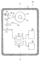
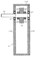
図1は、本発明の角度測定装置の構成を概念的に表わしたもので、図2は図1におけるA−A断面図である。 FIG. 1 conceptually shows the configuration of the angle measuring apparatus of the present invention, and FIG. 2 is a cross-sectional view taken along line AA in FIG.
角度測定装置10は、図1に示すように、本体を形成する筐体、筐体に後出のベアリングを介して回転自在に支持された軸体12、軸体に固定された平面鏡であるポリゴンミラー13、ポリゴンミラー13の回転角度を検出する検出部14、検出部からの検出データを処理して角度を算出する処理部31、算出された測定データを表示する表示部34、及び外部に信号を出力する出力部35等から構成されている。
As shown in FIG. 1, the
検出部14は、投光部であるレーザーダイオード15、コリメートレンズ16、ミラー17、エフシータレンズ(fθレンズ)18、及び受光部であるラインセンサ19を有している。また、処理部31は、ラインセンサ19のデータをカウントするカウンタ32、及びカウンタ32によるカウント値から角度を演算する演算器33を有している。
The
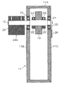
図2に示すように、筐体11は、枠体11A、後板11B、前板11Cとからなっており、後板11B及び前板11Cの夫々に取り付けられたベアリング21で軸体12を回転自在に支持している。
As shown in FIG. 2, the
軸体12にはポリゴンミラー13が、夫々螺子23によって軸体12に固定される2個の固定リング22、22で挟み込まれて、軸体12に固定支持されている。
A
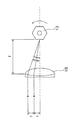
図3は、エフシータレンズ18の機能を説明するための概念図である。エフシータレンズ18は、2枚のレンズ面の曲率を変えることにより、レンズの周辺部と中心部とで走査速度が一定になるように設計されたものである。そのため、エフシータレンズ18の焦点距離fの位置から入射されるビームの入射角度(θラジアン)に比例した理想像高(y)が得られ、y=fθの関係を有している。
FIG. 3 is a conceptual diagram for explaining the function of the F-
従って、図3に示すように、エフシータレンズ18の焦点距離fの位置に反射面を有するポリゴンミラー13を回転させた場合、エフシータレンズ18への反射光ビームの入射角度の変化がエフシータレンズ18の径方向の位置変化に変換されるので、反射光ビームをエフシータレンズ18の径方向で検出することにより反射面の回転角度を算出することができ、また、反射面1面相当分のエフシータレンズ18の径方向のスキャン幅も検出することができる。
Therefore, as shown in FIG. 3, when the
また、エフシータレンズ18の径方向におけるスキャン回数をカウントすることにより、対応した反射面の数が分るので、ポリゴンミラー13の回転数も算出することができる。
Further, by counting the number of scans in the radial direction of the F-
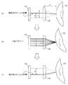
図4は、このエフシータレンズ18を用いてポリゴンミラー13の回転角度を算出する方法を表わしたもので、図4(a)はポリゴンミラー13の回転前の状態を表わしている、また、図4(b)はポリゴンミラー13が回転して、ポリゴンミラー13の複数の反射面からの反射光ビームがラインセンサ19上をスキャンしている状態を表わし、図4(c)はポリゴンミラー13が所定角度回転した後の状態を表わしている。
FIG. 4 shows a method for calculating the rotation angle of the
図において、fはエフシータレンズ18の焦点距離、Lは反射光ビームによるラインセンサ19上のスキャン幅、αはポリゴンミラー13の回転前の状態における反射光ビームのラインセンサ19上のスキャン幅最下端からの位置、βはポリゴンミラー13が所定角度回転した後の、反射光ビームのラインセンサ19上のスキャン幅最上端からの位置、mはラインセンサ19上の反射光ビームによるスキャン回数を表わしている。
In the figure, f is the focal length of the F-
また、ポリゴンミラー13がn個の反射面を有するn面反射体の場合、反射面1面に相当する角度は(360/n)度で表わされるから、ポリゴンミラー13の回転角度R(度)は次式(1)
![]()
![]()
なお、前出の図3、及び図4において、ポリゴンミラー13に対する入射側ビームの記載は省略してある。
In FIGS. 3 and 4 described above, the description of the incident side beam with respect to the
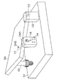
次に、本発明に係る角度測定装置10の作用について説明する。図5は工作機械等のチルチングテーブルの水平方向を軸とした回転角度を測定する状態を表わしている。チルチングテーブル54は、一端の側面で移動テーブル51の上面に取り付けられた2個のブロック52、52に設けられたピン53、53に回転可能に支持され、他端側で図示しないモータ等の駆動手段によって回転される螺子部材55に当接されており、螺子部材55の回転によりチルチングされるようになっている。
Next, the operation of the
角度測定装置10は、その軸体12をチルチングテーブル54の側面に形成された穴54Aに挿入し、ねじ54Bによって締め付けられてチルチングテーブル54に取り付けられる。
The
角度測定装置10の軸体12がチルチングテーブル54に固定されると、角度測定装置10は自重によって軸体12を支点として重力方向に垂下する。このため、軸体12に固定されたポリゴンミラー13と重力方向に垂下した筐体11との相対的な角度変化を求めることにより、チルチングテーブル54の角度変化を求めることができる。
When the
この状態で図1に示すように、レーザーダイオード15からレーザー光が照射され、コリメートレンズによってレーザービームBに絞られてポリゴンミラー13に照射される。
In this state, as shown in FIG. 1, laser light is emitted from the
ポリゴンミラー13に照射されたレーザービームBはミラー17で方向を変えられてエフシータレンズ18に入射する。ここでレーザービームBはエフシータレンズ18の光軸方向に向きを変えられてラインセンサ19に入射する。ラインセンサ19はこのレーザービームBの位置情報を処理部31に出力し、処理部31では図示しないメモリに初期位置として記憶する。
The laser beam B irradiated to the
次に、図示しないモータ等の駆動手段によって螺子部材55が回転され、チルチングテーブル54が所定角度回転する。この間、レーザービームBはラインセンサ19内をスキャンするので、ラインセンサ19の各ピクセルは次々と検出信号を処理部31に出力し、出力された検出信号は処理部31のカウンタ32でカウントされ、このカウント値を基に演算器33がポリゴンミラー13の回転角度、即ちチルチングテーブル54の回転角度を算出する。
Next, the
なお、ポリゴンミラー13の各面の角度偏差は予め測定しておき、既知のデータとして処理部31に記憶させ、回転角度の算出時にこの偏差分を補正する。
The angle deviation of each surface of the
算出された測定結果は角度測定装置10の表示部34に表示されると共に、出力部35から外部に出力される。この出力部35は、角度測定装置10が重力方向に垂下する時に信号線による抵抗なくすため、無線で出力するのが好ましい。同様の理由で、角度測定装置10の筐体11内にバッテリーを搭載し、筐体11内の各部材をバッテリー駆動とすることが好ましい。
The calculated measurement result is displayed on the
このように、図示しない工作機械の制御装置によって制御されるチルチングテーブル54の傾斜精度を容易に測定することができる。 In this way, it is possible to easily measure the tilt accuracy of the tilting table 54 controlled by a machine tool control device (not shown).
また、図6に示すように、角度測定装置10の軸体12に取り付け面24Aが形成された固定ブロック24をねじ等で取り付け、角度測定装置10を取り付け面24Aで水平面に取り付けたときの、ラインセンサ上におけるレーザービームBの検出位置を記憶しておくことにより(原点位置記憶)、被測定物の水平面に対する傾斜角度も容易に測定することができる。
Further, as shown in FIG. 6, when the fixing block 24 having the
この場合、被測定物の水平面に対する傾斜角度が小さく、ポリゴンミラー13の反射面1面のみのスキャンで済む場合は、角度測定装置10を固定ブロック24で被測定物に取り付けるだけでよい。
In this case, if the inclination angle of the object to be measured is small relative to the horizontal plane and only the reflection surface 1 of the
更に、軸体12の固定ブロック24を取り付けた側と逆方向の端面に指標25を設け、前板11Cに角度測定装置10を水平面に取り付けたときに指標25と合致する合いマーク26を付しておくことにより、被測定物の水平面に対する傾斜角度が大きくてポリゴンミラー13の複数の反射面を使用する場合の水平面に対する傾斜角度の測定も行うことができる。
Further, an
この場合は、角度測定装置10を固定ブロック24の取り付け面24Aで被測定物に取り付け、軸体12に設けた指標25と前板11Cに設けた合いマーク26とが一致する位置に角度測定装置10を回転させて支持し、この位置でラインセンサ19からの信号のカウントを開始する。それから徐々に角度測定装置10の姿勢を重力方向まで戻し、そこまでのカウント値から被測定物の水平面に対する傾斜角度が算出されるようにすればよい。
In this case, the
この場合、処理部31では原点位置記憶で原点を記憶しているので、ラインセンサ19の各ピクセルで検知する信号のカウントを原点からカウントすることができるので、指標25と合いマーク26との一致が多少不正確であっても、精度よく傾斜角度を測定することができる。
In this case, since the origin is stored in the origin position storage in the
また、固定ブロック24の取り付け面24Aにマグネット材を埋設しておけば、角度測定装置10の被測定物への取り付けがより一層容易になる。
Further, if a magnet material is embedded in the
なお、前述の実施の形態では、角度検出にレーザー光を用いたが、本発明はレーザー光に限らず集光された光を用いてもよい。 In the above-described embodiment, laser light is used for angle detection. However, the present invention is not limited to laser light, and may use condensed light.
また、前述の実施形態では、被測定物としてチルチングテーブル54の例で説明したが、本発明の角度測定装置10はこれに限らず、種々の被測定物の水平方向を軸とした回転角度や傾きを容易に測定することができる。
In the above-described embodiment, the example of the tilting table 54 is described as an object to be measured. However, the
10…角度測定装置、11…筐体、12…軸体、13…ポリゴンミラー(平面鏡)、14…検出部、15…レーザーダイオード(投光部)、18…エフシータレンズ、19…ラインセンサ(受光部)、31…処理部、B…レーザービーム(レーザー光)
DESCRIPTION OF
Claims (4)
該角度測定装置の本体を形成する筐体と、
該筐体に回転自在に支持された軸体と、
該軸体に取り付けられ、軸体と共に回転する平面鏡と、
投光部、入射ビームの角度変化を位置変化に変換するエフシータレンズ、及び受光部とを有し、前記筐体に取り付けられた検出部と、が設けられ、
該検出部では前記投光部より前記平面鏡にレーザー光を出射し、前記平面鏡で反射されたレーザー光をエフシータレンズを介して前記受光部に導くように構成され、
測定時は前記軸体が前記被測定物に固定されることにより、前記筐体が重力方向に垂下し、前記軸体と前記筐体との相対的な回転角度が検出されることを特徴とする角度測定装置。 In the angle measuring device that measures the rotation angle around the horizontal direction of the object to be measured,
A housing forming the main body of the angle measuring device;
A shaft rotatably supported by the housing;
A plane mirror attached to the shaft and rotating together with the shaft;
A light projecting unit, an F-theta lens that converts the angle change of the incident beam into a position change, and a light receiving unit, and a detection unit attached to the housing, and
The detection unit is configured to emit laser light from the light projecting unit to the plane mirror, and to guide the laser beam reflected by the plane mirror to the light receiving unit via an F-theta lens,
During measurement, the shaft body is fixed to the object to be measured, so that the housing hangs down in the direction of gravity, and a relative rotation angle between the shaft body and the housing is detected. Angle measuring device.
Priority Applications (1)
| Application Number | Priority Date | Filing Date | Title |
|---|---|---|---|
| JP2004110134A JP2005292037A (en) | 2004-04-02 | 2004-04-02 | Angle measuring instrument |
Applications Claiming Priority (1)
| Application Number | Priority Date | Filing Date | Title |
|---|---|---|---|
| JP2004110134A JP2005292037A (en) | 2004-04-02 | 2004-04-02 | Angle measuring instrument |
Publications (1)
| Publication Number | Publication Date |
|---|---|
| JP2005292037A true JP2005292037A (en) | 2005-10-20 |
Family
ID=35325117
Family Applications (1)
| Application Number | Title | Priority Date | Filing Date |
|---|---|---|---|
| JP2004110134A Pending JP2005292037A (en) | 2004-04-02 | 2004-04-02 | Angle measuring instrument |
Country Status (1)
| Country | Link |
|---|---|
| JP (1) | JP2005292037A (en) |
Cited By (7)
| Publication number | Priority date | Publication date | Assignee | Title |
|---|---|---|---|---|
| US7701564B2 (en) * | 2005-05-18 | 2010-04-20 | Hitachi Global Storage Technologies Netherlands B.V. | System and method for angular measurement |
| JP2012093252A (en) * | 2010-10-27 | 2012-05-17 | Tokyo Seimitsu Co Ltd | Angle measuring method and angle measuring system |
| JP2013011631A (en) * | 2012-10-18 | 2013-01-17 | Tokyo Seimitsu Co Ltd | Angle measuring method and angle measuring system |
| JP2013079978A (en) * | 2013-01-23 | 2013-05-02 | Tokyo Seimitsu Co Ltd | Angle measuring method and angle measurement system |
| JP2015062030A (en) * | 2014-11-27 | 2015-04-02 | 株式会社東京精密 | Angle measurement method and angle measurement system |
| US9134145B2 (en) | 2013-04-03 | 2015-09-15 | Tokyo Seimitsu Co., Ltd. | Angle measuring method and angle measuring system |
| US9354088B2 (en) | 2012-02-15 | 2016-05-31 | Tokyo Seimitsu Co., Ltd. | Rotation angle measurement device and rotation angle measurement method |
-
2004
- 2004-04-02 JP JP2004110134A patent/JP2005292037A/en active Pending
Cited By (10)
| Publication number | Priority date | Publication date | Assignee | Title |
|---|---|---|---|---|
| US7701564B2 (en) * | 2005-05-18 | 2010-04-20 | Hitachi Global Storage Technologies Netherlands B.V. | System and method for angular measurement |
| JP2012093252A (en) * | 2010-10-27 | 2012-05-17 | Tokyo Seimitsu Co Ltd | Angle measuring method and angle measuring system |
| US9354088B2 (en) | 2012-02-15 | 2016-05-31 | Tokyo Seimitsu Co., Ltd. | Rotation angle measurement device and rotation angle measurement method |
| US9778075B2 (en) | 2012-02-15 | 2017-10-03 | Tokyo Seimitsu Co., Ltd. | Rotation angle measurement device and rotation angle measurement method |
| JP2013011631A (en) * | 2012-10-18 | 2013-01-17 | Tokyo Seimitsu Co Ltd | Angle measuring method and angle measuring system |
| JP2013079978A (en) * | 2013-01-23 | 2013-05-02 | Tokyo Seimitsu Co Ltd | Angle measuring method and angle measurement system |
| US9134145B2 (en) | 2013-04-03 | 2015-09-15 | Tokyo Seimitsu Co., Ltd. | Angle measuring method and angle measuring system |
| US9372099B2 (en) | 2013-04-03 | 2016-06-21 | Tokyo Seimitsu Co., Ltd. | Angle measuring method and angle measuring system |
| US9574908B2 (en) | 2013-04-03 | 2017-02-21 | Tokyo Seimitsu Co., Ltd. | Angle measuring method and angle measuring system |
| JP2015062030A (en) * | 2014-11-27 | 2015-04-02 | 株式会社東京精密 | Angle measurement method and angle measurement system |
Similar Documents
| Publication | Publication Date | Title |
|---|---|---|
| JP6560596B2 (en) | Surveying equipment | |
| US10816665B2 (en) | Surveying system | |
| EP2056066B1 (en) | Surveying Instrument | |
| US7841094B2 (en) | Optical instrument with angle indicator and method for operating the same | |
| EP2075530A2 (en) | Surveying instrument and surveying compensation method | |
| EP1321739B1 (en) | Position measuring instrument | |
| US10267659B2 (en) | Angle detecting device and surveying instrument | |
| JP2007071852A (en) | Apparatus and method for measuring deep hole | |
| JP2014219394A (en) | Apparatus for locating machine element | |
| US20230175844A1 (en) | Inclination sensor and data acquisition device | |
| JP2021067612A (en) | Scanner device | |
| EP3792593A1 (en) | Three-dimensional survey apparatus, three-dimensional survey method, and three-dimensional survey program | |
| US7193730B2 (en) | Eccentricity measuring instrument of polygon-mirror motor | |
| EP3187822B1 (en) | Surface shape measuring device | |
| JP2005292037A (en) | Angle measuring instrument | |
| CN109764952B (en) | Shaft jitter detection and rotating speed measurement method | |
| EP3772633B1 (en) | Surveying instrument | |
| US11692823B2 (en) | Three-dimensional survey apparatus, three-dimensional survey method, and three-dimensional survey program | |
| EP3795946A1 (en) | Three-dimensional survey apparatus, three-dimensional survey method, and three-dimensional survey program | |
| JP2008268000A (en) | Displacement measuring method and device | |
| JP2017134059A (en) | Three-dimensional measurement device with rotor in nested configuration | |
| JPH10293029A (en) | Surveying machine with machine height measurement function | |
| JP4418712B2 (en) | Tilt measuring instrument | |
| JP4745733B2 (en) | Electronic level | |
| JP2006084346A (en) | Surveying machine with tilting function |