JP2005292027A - Processor and method for measuring/restoring three-dimensional shape - Google Patents
Processor and method for measuring/restoring three-dimensional shape Download PDFInfo
- Publication number
- JP2005292027A JP2005292027A JP2004109920A JP2004109920A JP2005292027A JP 2005292027 A JP2005292027 A JP 2005292027A JP 2004109920 A JP2004109920 A JP 2004109920A JP 2004109920 A JP2004109920 A JP 2004109920A JP 2005292027 A JP2005292027 A JP 2005292027A
- Authority
- JP
- Japan
- Prior art keywords
- image
- measurement
- shape
- data
- plane
- Prior art date
- Legal status (The legal status is an assumption and is not a legal conclusion. Google has not performed a legal analysis and makes no representation as to the accuracy of the status listed.)
- Pending
Links
Images


Landscapes
- Length Measuring Devices By Optical Means (AREA)
Abstract
Description
本発明は、物体の多方向シルエット画像のデータを取得して、このデータから物体の三次元形状を復元できるようにした三次元形状計測・復元装置および方法に関する。 The present invention relates to a three-dimensional shape measurement / restoration apparatus and method that acquire data of a multidirectional silhouette image of an object and restore the three-dimensional shape of the object from this data.
近年、物体の形状を計測することは工業や医療、芸術など様々な分野において必須の技術である。一般に物体の形状計測法には触針による接触型とCCDカメラを用いた非接触型があるが、接触型は測定する際、物体の表面に触れるため、柔らかいものや壊れやすいものには利用できない。一方、非接触型の計測法は対象を傷つけること無く計測できるため、多くの機関で活発に研究されている。 In recent years, measuring the shape of an object is an essential technique in various fields such as industry, medicine, and art. In general, there are two types of object shape measurement methods: contact type using a stylus and non-contact type using a CCD camera, but the contact type touches the surface of the object when measuring, so it cannot be used for soft or fragile items. . On the other hand, non-contact type measurement methods can be measured without damaging the object, and are actively studied in many institutions.
三次元画像計測の手法を大きく二つに分けるとCCDカメラの他に音や光などの何らかのエネルギを用いる能動型と、それらエネルギを用いない受動型に分けられる。能動型計測ではスリットレーザを用いた光切断法や空間コード化された光パターンを投影するパターン光投影法があるが、光を吸収または反射する物体の計測は困難である。一方、受動型の代表的な計測法として、二台以上のCCDカメラの視差を利用したステレオ法があるが計測点が多数存在する場合、画像間での対応がとりにくい欠点がある。さらに能動型または受動型どちらの計測法も三角測量の原理を利用しており、計測器と対象の配置は一度キャリブレーションを行うと変更できない。そのため対象の背面を計測したい場合や対象の大きさや計測範囲に合わせCCDカメラを移動させる場合は、その都度CCDカメラのキャリブレーションを行わなければならない。 The three-dimensional image measurement method can be roughly divided into two types: an active type that uses some energy such as sound and light in addition to a CCD camera, and a passive type that does not use such energy. Active measurement includes a light cutting method using a slit laser and a pattern light projection method for projecting a spatially encoded light pattern, but it is difficult to measure an object that absorbs or reflects light. On the other hand, as a typical passive measurement method, there is a stereo method using the parallax of two or more CCD cameras. However, when there are many measurement points, there is a drawback that it is difficult to correspond between images. Furthermore, both active and passive measurement methods use the principle of triangulation, and the arrangement of measuring instruments and objects cannot be changed once calibrated. Therefore, when it is desired to measure the back surface of the object, or when the CCD camera is moved in accordance with the size or measurement range of the object, the CCD camera must be calibrated each time.
本発明は、キャリブレーションを行う必要がなく、かつレーザなどの光を吸収または反射する材質に対しても計測が可能な三次元形状計測・復元装置および方法を提供することを目的とする。 It is an object of the present invention to provide a three-dimensional shape measurement / restoration apparatus and method that do not require calibration and can measure even a material that absorbs or reflects light such as a laser.
本発明の三次元形状計測・復元処理装置は、被計測体である物体に対して相対的に移動可能な撮像手段と、少なくとも該撮像手段と前記物体との相対的な三次元位置と撮像姿勢方向とのデータを取得できる位置センサと、前記撮像手段で得られた画像データと前記相対的な三次元位置と撮像姿勢方向とのデータを用いて前記物体の形状に関する復元可能なデータとして処理する画像処理手段と、を備えたことを特徴とする。
この特徴によれば、計測を行う前にキャリブレーションを行うことで計測時間の短縮と全ての輪郭計測において同条件での計測が可能になる。また一度キャリブレーションを行うことで、CCDカメラを動かした際もその動きは三次元磁気センサによって計測されるため、その都度、CCDカメラのキャリブレーションを行う必要がない。更に、この計測法ではCCDカメラ一台のみで計測を行うため画像間の対応をとる必要が無く、またレーザなどの光を吸収または反射する材質の物体に対しても計測が可能となる。
好適な実施態様としては、三次元位置と姿勢方向を検出できる三次元磁気センサ(3 SPACE FASTRACK Polhemus Inc.)をCCDカメラに取り付けることにより、CCDカメラを自由に動かし多方向からのシルエット画像を得ることで計測物体形状を復元出来る。
The three-dimensional shape measurement / restoration processing apparatus according to the present invention includes an imaging unit that can move relative to an object that is a measurement object, and a relative three-dimensional position and an imaging posture of at least the imaging unit and the object. Using the position sensor that can acquire the direction data, the image data obtained by the imaging unit, the data of the relative three-dimensional position and the imaging posture direction, the data is processed as recoverable data relating to the shape of the object. And an image processing means.
According to this feature, by performing calibration before measurement, measurement time can be shortened and measurement under the same conditions is possible in all contour measurements. Further, once the calibration is performed, even when the CCD camera is moved, the movement is measured by the three-dimensional magnetic sensor. Therefore, it is not necessary to calibrate the CCD camera each time. Furthermore, in this measurement method, since measurement is performed with only one CCD camera, it is not necessary to take correspondence between images, and it is possible to measure an object made of a material that absorbs or reflects light such as a laser.
As a preferred embodiment, a three-dimensional magnetic sensor (3 SPACE FASTRACK Polhemus Inc.) capable of detecting a three-dimensional position and orientation direction is attached to the CCD camera, so that the CCD camera can be moved freely to obtain silhouette images from multiple directions. The measured object shape can be restored.
本発明の実施例1を図1ないし図10で説明する。 A first embodiment of the present invention will be described with reference to FIGS.
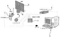
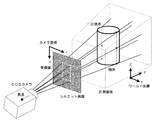
図1に第1実施例の基本的装置構成を示す。装置は、カメラユニットA、三次元磁気センサ2、制御を行う回路7およびPC3(パーソナルコンピュータ)等で構成される。
FIG. 1 shows a basic apparatus configuration of the first embodiment. The apparatus includes a camera unit A, a three-dimensional
三次元磁気センサ2(以下レシーバ)はトランスミッタ4から発信される半径80cm半球内の磁界ベクトルを検出している。また、三次元センサコントローラ5はレシーバ位置三成分と姿勢の三成分をサンプリング周波数120Hzで出力している。
レシーバ2はCCDカメラ1を固定したカメラユニットAに取り付けてあり、カメラユニットAを動かした際もその動きは三次元センサ2によって計測される。
シルエット画像の撮影に同期して、カメラユニットAの位置と姿勢が計測される。これらの制御はPLDによる回路およびPCで行われる。
物体B後方にある黒板6は対象のシルエット画像を撮りやすくするために使用する。
The three-dimensional magnetic sensor 2 (hereinafter referred to as a receiver) detects a magnetic field vector in a hemisphere having a radius of 80 cm transmitted from the
The
The position and posture of the camera unit A are measured in synchronization with the capturing of the silhouette image. These controls are performed by a PLD circuit and a PC.
The blackboard 6 behind the object B is used to make it easy to take a target silhouette image.
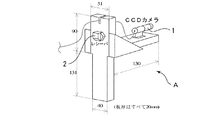
図2にカメラユニットの詳細が示され、カメラユニットAはCCDカメラ1が固定されており、その中心軸上にレシーバ2を取り付けてある。
レシーバ2はトランスミッタ4から発信される磁気を検出しており、周辺に金属などがあると計測結果にその影響を受ける。そのため、カメラユニットAは木材やプラスチック、アルミ製の材料で作成している。
FIG. 2 shows the details of the camera unit. In the camera unit A, the CCD camera 1 is fixed, and the
The
本実施例では、シルエット画像から計測対象輪郭の受像面上の座標を計測しており、
得られた画像に二値化、輪郭抽出などの画像処理を行い、シルエット画像Cを得る。
In this example, the coordinates on the image receiving surface of the measurement target contour are measured from the silhouette image,
Image processing such as binarization and contour extraction is performed on the obtained image to obtain a silhouette image C.
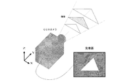
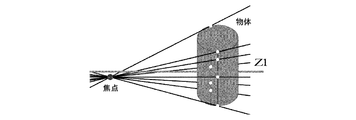
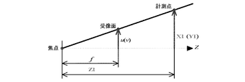
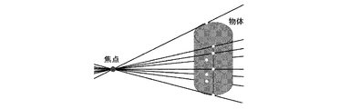
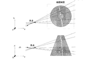
ここで、カメラ1とシルエット画像の関係を説明すると、図3にその遠近法の原理を示しており、計測対象が存在する候補領域は撮影されたシルエット影像を断面に持つとともに、遠近法の原理によりカメラ1から離れるほど、広い領域となる。 Here, the relationship between the camera 1 and the silhouette image will be described. FIG. 3 shows the principle of the perspective method. The candidate area where the measurement target exists has a photographed silhouette image in cross section, and the principle of the perspective method. As the distance from the camera 1 increases, the area becomes wider.
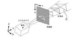
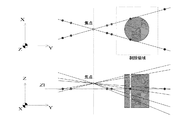
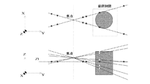
これらの関係は、図4、図5に座標関係で示されている。すなわち、(u、v)は受像面上の座標、(X、Y、Z)はワールド座標系であり、図4のようにカメラ1の焦点から受像上の対象の点を通る直線は、実際の対象上の点も通過する。そのため、受像面上の計測点座標がわかれば、実際の対象上にある計測点を通る直線を算出できる。 These relationships are shown as coordinate relationships in FIGS. That is, (u, v) are coordinates on the image receiving plane, (X, Y, Z) are world coordinate systems, and a straight line passing through the target point on the image receiving from the focus of the camera 1 as shown in FIG. A point on the object of also passes. Therefore, if the measurement point coordinates on the image receiving surface are known, a straight line passing through the measurement points on the actual target can be calculated.
本実施例では、計測対象のシルエット画像Cより得られた受像面上の計測点とカメラの焦点を結ぶ直線をワールド座標系(物体に固定した座標系)上で、算出することで対象を含む領域を取り出す。 In this embodiment, the object is included by calculating on the world coordinate system (coordinate system fixed to the object) a straight line connecting the measurement point on the image receiving surface obtained from the silhouette image C to be measured and the focal point of the camera. Take out the area.
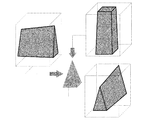
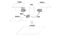
ここでシルエット画像からの形状復元イメージについて説明する。シルエット画像から計測対象の形状を復元する例として、人が彫刻などを行う際の技術をイメージして試作するような場合を想定し、図5のように立方体から四角錐を削り出していく場合を考える。 Here, the shape restoration image from the silhouette image will be described. As an example of restoring the shape of a measurement object from a silhouette image, assuming a case where a prototype is created in the image of the technique used when a person performs sculpture, etc., and a quadrangular pyramid is cut out from a cube as shown in FIG. think of.
まず、図6のように、計測対象を正面、側面、上面方向からCCDカメラ1で計測し、設定した領域で削り出す。つぎに、図6で削り出された立方体を重ね合わせると、図7のような計測形状の四角錐を削り出すことができる。 First, as shown in FIG. 6, the measurement target is measured by the CCD camera 1 from the front, side, and top directions, and is cut out in the set area. Next, when the cubes cut out in FIG. 6 are overlapped, a quadrangular pyramid having a measurement shape as shown in FIG. 7 can be cut out.
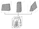
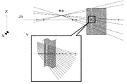
図7では目標となる図5の図形より形がいびつであるが、さらに別の方向からも計測を行い、削り出していくことで形状復元が可能である。この手法では、対象が複雑な形状であっても、より多くの方向から計測を行い全ての結果を重ねることで形状復元が可能である。この技術を応用し、図8のように計測対象の多方向からのシルエット画像を取得することで対象の形状を復元することができる。 In FIG. 7, the shape is more irregular than the target figure of FIG. 5, but the shape can be restored by measuring from another direction and cutting out. In this method, even if the target has a complicated shape, the shape can be restored by measuring from more directions and overlapping all the results. By applying this technique and acquiring silhouette images from multiple directions of the measurement object as shown in FIG. 8, the shape of the object can be restored.
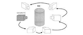
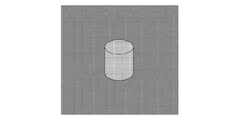
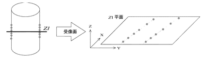
まず、合成された領域上に水平なZ=Z1平面を設定し、その断面形状を取り出す。図9のように円柱を多方向から計測し、合成された対象の断面形状イメージ図を示す。 First, a horizontal Z = Z1 plane is set on the synthesized region, and its cross-sectional shape is taken out. As shown in FIG. 9, a cylinder is measured from multiple directions, and a cross-sectional image diagram of the synthesized object is shown.
そして、図9で得られた断面形状のデータより、輪郭形状のみを取り出す。更に、設定した水平なZ=Z1平面を変更していき、各平面上における断面形状を取り出す。図10のように各高さの断面形状をまとめ、計測対象の形状を復元する。 Then, only the contour shape is extracted from the cross-sectional shape data obtained in FIG. Further, the set horizontal Z = Z1 plane is changed, and the cross-sectional shape on each plane is taken out. As shown in FIG. 10, the cross-sectional shapes at the respective heights are collected, and the shape of the measurement target is restored.
この計測手順は、
(1) カメラを移動させながら多方向からの撮影を行い、各方向からのシルエット画像を得る。
(2) 各シルエット画像を基にそれぞれの撮影方向において、計測対象を含む候補領域を抽出する。
(3) 抽出された候補領域内に水平面と平行な面を設定し、その平面上で候補領域の断面形状を算出する。
(4) (3)の処理を異なる撮影方向から得られた候補領域に対し行う。
(5) 同一平面内で様々な撮影方向から得られた候補領域の断面形状を重ね合わせ
重複した部分を抽出することで、計測対象のその平面での断面形状が決定される。
(6) (3)で設定した平面を上下に移動し、それぞれの平面上で対象の断面形状の算出を繰り返すことで,対象全体の形状を復元する。
という手順で説明を行っている。
This measurement procedure is
(1) Shooting from multiple directions while moving the camera to obtain silhouette images from each direction.
(2) Extract candidate areas including the measurement target in each shooting direction based on each silhouette image.
(3) A plane parallel to the horizontal plane is set in the extracted candidate area, and the cross-sectional shape of the candidate area is calculated on the plane.
(4) The process of (3) is performed on candidate areas obtained from different shooting directions.
(5) The cross-sectional shape of the measurement object in the plane is determined by extracting the overlapping and overlapping portions of the cross-sectional shapes of the candidate regions obtained from various shooting directions in the same plane.
(6) The plane set in (3) is moved up and down, and the calculation of the cross-sectional shape of the target is repeated on each plane to restore the shape of the entire target.
The procedure is described as follows.
第2実施例は、第1実施例と異なる手順で対象全体を復元する方法であり、図11ないし図20で説明する。 The second embodiment is a method for restoring the entire object in a different procedure from the first embodiment, and will be described with reference to FIGS.
すなわち、第2実施例の計測手順は、
(1) 一方向から対象を撮影しシルエット画像を得る。
(2) 撮影されたシルエット画像を基に計測対象を含む候補領域を抽出する。
(3) 取り出した候補領域内に水平面と平行な面を設定し、その平面上の候補領域の断面形状を算出する。
(4) (3)で設定した平面の位置を上下方向に移動し、それぞれの平面上で候補領域の断面形状の算出を繰り返すことで,候補領域全体の形状を算出する。
(5) カメラを移動させながら多方向からの撮影を行い、それぞれの方向から算出された候補領域形状を重ね、重複した部分を抽出することで対象の形状を復元する。
という手順で行う。
That is, the measurement procedure of the second embodiment is as follows:
(1) A subject is photographed from one direction to obtain a silhouette image.
(2) Extract candidate areas including the measurement object based on the captured silhouette image.
(3) A plane parallel to the horizontal plane is set in the extracted candidate area, and the cross-sectional shape of the candidate area on the plane is calculated.
(4) The shape of the entire candidate region is calculated by moving the position of the plane set in (3) in the vertical direction and repeating the calculation of the cross-sectional shape of the candidate region on each plane.
(5) Image is taken from multiple directions while moving the camera, the candidate area shapes calculated from the respective directions are overlapped, and the overlapping portion is extracted to restore the target shape.
Follow the procedure.
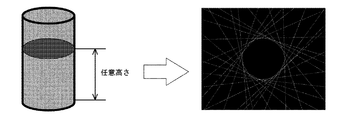
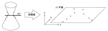
すなわち、本実施例では、対象の断面形状より対象の形状を復元している。図11のように円柱を計測した場合を例に説明する。 That is, in this embodiment, the shape of the object is restored from the cross-sectional shape of the object. A case where a cylinder is measured as shown in FIG. 11 will be described as an example.
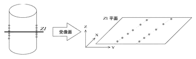
図11は各座標系の関係を示しており、図12は直線方程式イメージ図である。実際は輪郭全てに対して輪郭点が計測されており、それぞれの点に直線の方程式が算出されている。 FIG. 11 shows the relationship between the coordinate systems, and FIG. 12 is a linear equation image diagram. Actually, contour points are measured for all contours, and a linear equation is calculated for each point.
図12において水平面と平行な面Z=Z1を設定し、各直線との交点X、Yを算出する。またX、Yについても領域を設定し、水平面と平行な面Z=Z1近傍の形状をZ1平面上に取り出す。 In FIG. 12, a plane Z = Z1 parallel to the horizontal plane is set, and intersections X and Y with each straight line are calculated. Further, regions are set for X and Y, and the shape in the vicinity of the plane Z = Z1 parallel to the horizontal plane is taken out on the Z1 plane.
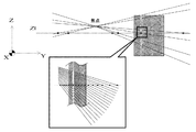
図13に円柱を計測した場合の計測領域設定について示す。 FIG. 13 shows the measurement area setting when a cylinder is measured.
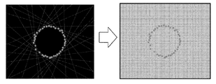
図14は、図13を一部、拡大した図であり、全輪郭点について直線の方程式を算出すると、図14のようにZ=Z1平面上の対象形状候補を点群で取り出す事ができる。 FIG. 14 is a partially enlarged view of FIG. 13. When straight line equations are calculated for all contour points, target shape candidates on the Z = Z1 plane can be extracted as point groups as shown in FIG.
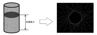
図15にはZ=Z1平面上に抽出された輪郭のイメージ図が示されており、この図15により、ある方向から計測されたZ1平面上の対象形状を取り出すことができる。これはある一方向からのデータである。 FIG. 15 shows an image of the contour extracted on the Z = Z1 plane. With this FIG. 15, the target shape on the Z1 plane measured from a certain direction can be taken out. This is data from one direction.
つぎに、カメラを移動させながら各方向シルエット画像を計測し、任意高さZ=Z1平面状の形状を算出していく。得られた全てのZ1平面上の形状を重ねていく事で、任意高さZ=Z1の断面形状を得ることができる。 Next, each direction silhouette image is measured while moving the camera, and an arbitrary height Z = Z1 planar shape is calculated. By superimposing all the obtained shapes on the Z1 plane, a cross-sectional shape having an arbitrary height Z = Z1 can be obtained.
図16には多方向からの計測イメージ図が示されているが、実際の計測を行う際には、カメラの移動間隔を狭め、より多くのシルエット画像を得る事で良好な形状復元が行える。 FIG. 16 shows a measurement image diagram from multiple directions. However, when actual measurement is performed, a good shape restoration can be performed by narrowing the camera movement interval and obtaining more silhouette images.
多方向からの計測を行い、各方向の全ての輪郭形状を重ねると図17のように水平面と平行な任意平面における断面形状が点群の曲線で計測できる。そして、各曲線の交点を求め、輪郭のみのデータを算出する。図18のように得られた点群について交点を求めていくことで図17のように対象形状のみのデータを得る事ができる。 When measurement is performed from multiple directions and all contour shapes in each direction are overlapped, the cross-sectional shape in an arbitrary plane parallel to the horizontal plane can be measured with a point cloud as shown in FIG. And the intersection of each curve is calculated | required and the data of only an outline are calculated. By obtaining the intersection point for the point group obtained as shown in FIG. 18, data of only the target shape can be obtained as shown in FIG.
つぎに任意に設定した平面Z=Z1の高さを変えていき、各断面の形状を算出する。最後に図19のように全ての結果より対象の形状を復元する。 Next, the height of the arbitrarily set plane Z = Z1 is changed, and the shape of each cross section is calculated. Finally, the target shape is restored from all the results as shown in FIG.
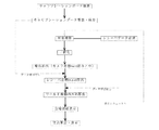
図20には計測の流れをフローチャートで示されており、具体的には、
(1)計測を行う前にキャリブレーションを行う。先にキャリブレーションを行うことで計測時間の短縮と全ての輪郭計測において同条件での計測が可能になる。
(2)対象をCCDカメラで取り込み、同時にCCDカメラの位置と姿勢をレシーバにより計測する。得られた画像に二値化、輪郭抽出などの処理を行い、カメラ座標を読み取る。
(3)キャリブレーションデータを元にカメラ座標をレシーバ座標に変換し、更にレシーバ座標を撮影時のカメラの位置と姿勢を元にワールド座標に変換する。
(4)カメラを移動させつぎのシルエットの撮影を行い、(2)〜(3)を繰り返す。
(5)全ての輪郭の計測が終了したら全輪郭を表示し、交点を算出する。
(6)全ての結果より対象の形状を復元する。
となる。
FIG. 20 is a flowchart showing the measurement flow. Specifically,
(1) Perform calibration before measurement. By performing calibration first, measurement time can be shortened and measurement under the same conditions can be performed for all contour measurements.
(2) The object is captured by the CCD camera, and at the same time, the position and orientation of the CCD camera are measured by the receiver. Processing such as binarization and contour extraction is performed on the obtained image, and the camera coordinates are read.
(3) The camera coordinates are converted into receiver coordinates based on the calibration data, and the receiver coordinates are further converted into world coordinates based on the position and orientation of the camera at the time of shooting.
(4) Move the camera to shoot the next silhouette, and repeat (2) to (3).
(5) When the measurement of all the contours is completed, all the contours are displayed and the intersection point is calculated.
(6) The target shape is restored from all results.
It becomes.
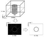
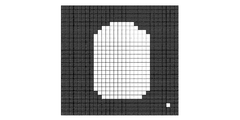
前記したフローの(2)における二値化について説明すると、本実施例で得られる画像は分解能512×512の濃淡画像であり、ピクセルごとに明るさレベル(輝度値)を持っている。輝度値に対し閾値を設定し、二値化を行う。二値化を行いやすくするため、対象の後ろに黒いボードを設置して撮影している。図21に円柱の対象をある方向から撮影したイメージ図を示す。 Describing the binarization in (2) of the flow described above, the image obtained in this embodiment is a grayscale image with a resolution of 512 × 512, and has a brightness level (luminance value) for each pixel. A threshold is set for the luminance value, and binarization is performed. In order to facilitate binarization, a black board is placed behind the subject for shooting. FIG. 21 shows an image of a cylindrical object taken from a certain direction.
図22に図21の対象周辺を拡大した図を示す。背景に黒いボードを設置した事で対象周辺は輝度値が高く、それ以外は輝度値が低くなる。図22の対象左上と右下の点はノイズを示している。 FIG. 22 shows an enlarged view around the object of FIG. By installing a black board in the background, the luminance value around the target is high, and the luminance value is low otherwise. The upper left and lower right points in FIG. 22 indicate noise.
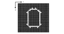
図21の濃淡画像に対し閾値を設定し、輝度値が閾値より高い場合は「1」、低い場合は「0」とし二値化を行う。本システムでは二値化の際「1」を白、「0」を黒で表している。二値化を行う事で、図22は図23のような対象のシルエット画像を得る事ができる。対象右下の点はノイズを示している。 A threshold value is set for the grayscale image in FIG. 21, and binarization is performed with “1” when the luminance value is higher than the threshold value and “0” when the luminance value is lower. In the present system, “1” is represented by white and “0” is represented by black at the time of binarization. By performing binarization, FIG. 22 can obtain the target silhouette image as shown in FIG. The point on the lower right of the subject indicates noise.
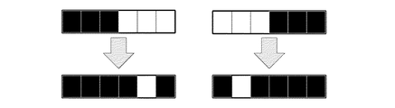
同様に、フロー(2)における輪郭抽出について説明すると、二値化(白黒化)された画像より輪郭を抽出する場合、二値化画像は各ピクセルが「1(白)」と「0(黒)」、どちらかに処理されており、対象シルエットは、ある幅の「1」の塊を持っていると考えられる。そこで,図24のようにピクセルを左から右へと横に走査していき、「000111」の場合は「000010」、または「111000」の場合は「010000」と処理する事で対象の右端、左端の輪郭が抽出される。またこの処理は同時にノイズ除去にもなる。このように、輪郭抽出を行う事で図25のように対象の輪郭のみが抽出され、ノイズは除去される。 Similarly, the contour extraction in the flow (2) will be described. When a contour is extracted from a binarized (monochrome) image, each pixel of the binarized image is “1 (white)” and “0 (black). ) ”, The target silhouette is considered to have a“ 1 ”chunk of a certain width. Therefore, as shown in FIG. 24, the pixels are scanned horizontally from left to right. When “000111” is processed, “000010” is processed, or when “111000” is processed, “010000” is processed. The leftmost contour is extracted. This process also eliminates noise. Thus, by performing contour extraction, only the target contour is extracted as shown in FIG. 25, and noise is removed.
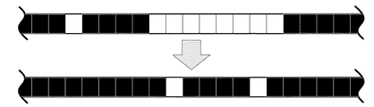
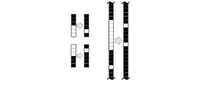
この工程を図26のように上から下に対しても同様の処理を行い、二値化された画像を上下左右,全ピクセルに対し輪郭抽出を行う事で、図23は図27、図28のようになる。すなわち、図27の画像により対象輪郭が決定され各点のカメラ座標(u,v)が決まる。 This process is performed in the same way from top to bottom as shown in FIG. 26, and the binarized image is extracted from the top, bottom, left, right, and all pixels, so that FIG. become that way. That is, the target contour is determined from the image of FIG. 27, and the camera coordinates (u, v) of each point are determined.
本実施例では得られた対象の各輪郭カメラ座標(u,v)を座標変換することで実際の座標(X,Y,Z)を算出する。以下に座標変換について記述する。 In this embodiment, the actual coordinates (X, Y, Z) are calculated by performing coordinate transformation on the obtained contour camera coordinates (u, v) of the object. The coordinate transformation is described below.
前述したフロー(3)におけるカメラ座標系からレシーバ座標系(焦点と計測点を通る直線の算出方法)を説明すると、本実施例には、トランスミッタを基準にした実座標であるワールド座標系、カメラの焦点距離を基準にしたカメラ座標系、レシーバを基準としたレシーバ座標系が存在することになる。 The receiver coordinate system (calculation method of a straight line passing through the focal point and the measurement point) from the camera coordinate system in the flow (3) described above will be described. In this embodiment, the world coordinate system, which is the actual coordinate based on the transmitter, the camera There are a camera coordinate system based on the focal length of the receiver and a receiver coordinate system based on the receiver.
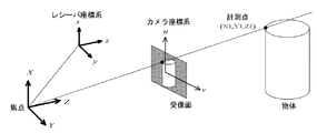
ここでは、カメラで撮影した点をカメラ座標からレシーバ座標へ変換し、さらにレシーバ座標をワールド座標に変換する事で実座標を算出している。図29にカメラ座標、レシーバ座標、ワールド座標の関係を示す。 Here, the actual coordinates are calculated by converting the points captured by the camera from the camera coordinates to the receiver coordinates, and further converting the receiver coordinates to the world coordinates. FIG. 29 shows the relationship between camera coordinates, receiver coordinates, and world coordinates.
計測対象をCCDカメラで撮影し二値化・輪郭抽出などの画像処理を行った後,輪郭のカメラ座標上での位置(u,v)を読み取る。CCDカメラの焦点と計測点通る直線を算出し,レシーバを原点とした座標系(x,y,z)に変換する。同時にCCDカメラの位置や姿勢をレシーバにより計測し,最後にレシーバ座標を三次元磁気センサからの位置と姿勢のデータを組み合わせることでワールド座標(X,Y,Z)に変換する。 The measurement object is photographed with a CCD camera and subjected to image processing such as binarization and contour extraction, and then the position (u, v) of the contour on the camera coordinates is read. A straight line passing through the CCD camera focus and measurement point is calculated and converted to a coordinate system (x, y, z) with the receiver as the origin. At the same time, the position and orientation of the CCD camera are measured by the receiver, and finally the receiver coordinates are converted into world coordinates (X, Y, Z) by combining the position and orientation data from the 3D magnetic sensor.
まず,カメラ座標からレシーバ座標。への変換について説明する。図30に図29をX1-Z1(Y1-Z1)平面で二次元化したカメラ焦点と受像面及び計測点までの距離の関係を示す。 First, receiver coordinates from camera coordinates. The conversion to will be described. FIG. 30 shows the relationship between the camera focus, the image receiving surface, and the distance to the measurement point obtained by making FIG. 29 two-dimensional on the X1-Z1 (Y1-Z1) plane.
カメラの焦点から受像面までの距離をfとおくと,受像面上の座標(カメラ座標)はカメラの焦点を原点とした座標系において以下のように表せられる。

Z 1=λとおき、線形化すると以下のように表せられる。
(4.2)式をレシーバを原点とした座標(レシーバ座標)で表すために回転と平行移動を行う。
カメラ座標原点からレシーバ座標原点への平行移動量は、ベクトルa=(xr,yr,zr)となる。
これら回転と平行移動の変化を(4.2)式に導入すると、
When these changes in rotation and translation are introduced into equation (4.2),
となり、代数h11〜h34を設定すると、以下のような行列で表すことができる。
ここでx,y,zは三次元位置センサのレシーバ座標である。
また、(4.5)式をh34で両辺を割り、代数s,k11〜k33で置き換えると次式で表すことができる。
Further, when the formula (4.5) is divided by h 34 and both sides are divided and replaced by the algebra s, k 11 to k 33 , it can be expressed by the following formula.
k11〜k33のパラメータには、カメラの位置や姿勢などをはじめとする計測対象とカメラの関係を表すデータが全て含まれている。したがって、式(4.8)が、レシーバ座標(x,y,z)とカメラ座標(u,v)の関係式となる。
(4.8)式を展開すると、
(4.8)
更に変形させることで、
ここで未知数である11個の係数k11〜k33は、4.5で述べる方法によって、既知の11点以上のカメラ座標(u,v)とその点に対応するレシーバ座標(x,y,z)の組み合わせを(4.9)式に代入し、連立方程式を解くことで求められる。 Here, eleven coefficients k 11 to k 33 which are unknown numbers are obtained by calculating the camera coordinates (u, v) of 11 or more known points and the receiver coordinates (x, y, z) corresponding to the points by the method described in 4.5. This is obtained by substituting the combination of (4) into equation (4.9) and solving simultaneous equations.
(4.10)は2平面の方程式であり、これを満たすものは2平面の交線を示す。この交線は、カメラの焦点と計測点を通る直線の方程式である。ただし、ここで求まる直線はCCDカメラに固定したレシーバ座標系であり、4.25、4.26で説明する方法で、ワールド座標系(計測物体に固定した座標系)に変換する。 (4.10) is an equation of two planes, and those satisfying this represent an intersection of the two planes. This intersection line is an equation of a straight line passing through the focal point of the camera and the measurement point. However, the straight line obtained here is the receiver coordinate system fixed to the CCD camera, and is converted to the world coordinate system (coordinate system fixed to the measurement object) by the method described in 4.25 and 4.26.
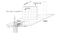
前述した計測を行う前のキャリブレーションについて説明すると、初めにレシーバ座標とカメラ座標の校正をとるためにキャリブレーションを行う。ここで、図31にはキャリブレーションの概要が示され、以下の手順で行われる。
(1) 50mmおきに目盛りの刻まれたキャリブレーションボードをCCDカメラに固定されているレシーバのx−y平面と平行に設置する。
(2) キャリブレーションボードを撮影し,ディスプレイ上に表示する。
(3) ディスプレイ上のキャリブレーションボード目盛りをマウスでクリックする(カメラ座標(u,v)の読み込み)。
(4) (3)でクリックした点と対応するレシーバ座標を入力する(レシーバ座標(x,y,z)の読み込み)。
(5) (3)〜(4)の処理を4回繰り返す。
(6) キャリブレーションボードをz軸方向に移動させながら(2)〜(5)の処理を4回繰り返す。
The calibration before performing the above-described measurement will be described. First, calibration is performed to calibrate the receiver coordinates and the camera coordinates. Here, FIG. 31 shows an outline of calibration, which is performed in the following procedure.
(1) A calibration board with graduations every 50 mm is placed parallel to the xy plane of the receiver fixed to the CCD camera.
(2) Take a picture of the calibration board and display it on the display.
(3) Click the calibration board scale on the display with the mouse (read camera coordinates (u, v)).
(4) The receiver coordinates corresponding to the point clicked in (3) are input (reading receiver coordinates (x, y, z)).
(5) The processes (3) to (4) are repeated four times.
(6) The processes (2) to (5) are repeated four times while moving the calibration board in the z-axis direction.
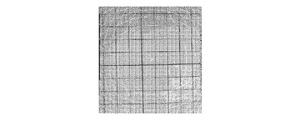
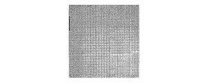
図32と図33は、レシーバを原点として、それぞれz=400mmとz=650mm時に撮影される画像である。奥行きを変えることで目盛りの大きさが変化するのがわかる。 32 and 33 are images taken when the receiver is the origin and z = 400 mm and z = 650 mm, respectively. You can see that changing the depth changes the size of the scale.
以上の手続きにより得られたデータを式(4.11)に代入すると,以下のような式が導出される。
![]()
![]()
ここでT, k, cは、
11個の未知数k11〜k33はTの擬似逆行列T*を用いて以下の式より算出される。
![]()
![]()
キャリブレーションにより未知数k11〜k33を算出した事で,式(4.10)より計測点のカメラ座標(u , v)が得られたときの一般式が決定する。
また、式(4.15)は次式のように表される。
次に、CCDカメラと輪郭上の計測点を結ぶ直線を求めるために平面の交線を求める。
一般的な平面の式は、
![]()
The general plane equation is
![]()
または変形して、
![]()
![]()
式(4.16)をそれぞれの平面の式と考えると、計測点はそれぞれの平面上に存在する。
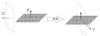
CCDカメラと計測点を結ぶ直線は、二平面それぞれに垂直なベクトルの外積を求める事で、算出する。それぞれの式の平面に垂直なベクトルは、
![]()
![]()
図34に、それぞれの面に垂直なベクトルの外積を示す。
外積cはベクトルaとベクトルbにそれぞれ垂直なベクトルである。
ベクトルaとベクトルbの外積cを求めると、
The outer product c is a vector perpendicular to the vectors a and b.
When the outer product c of the vector a and the vector b is obtained,
これを媒介変数表示によって表すと以下のようになる。
α,β,γはこの直線がz=0平面を通ることを考慮し、z=0とおき式(4.19)の連立方程式を解く事で求められる。
(4.23)はレシーバ座標なので4.25、4.26で述べる方法により、ワールド座標へ変換する。 Since (4.23) is receiver coordinates, it is converted to world coordinates by the method described in 4.25 and 4.26.
また、レシーバ座標からワールド座標への変換について詳述する。 The conversion from receiver coordinates to world coordinates will be described in detail.
すなわち、カメラユニットの動きを考慮するためレシーバ座標をワールド座標に変換する必要があり、カメラユニットを動かした場合、その動きはレシーバによって計測されている。 That is, in order to consider the movement of the camera unit, it is necessary to convert the receiver coordinates to world coordinates. When the camera unit is moved, the movement is measured by the receiver.
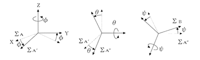
レシーバによって得られる値はトランスミッタ座標を原点としたレシーバの三次元的位置(wx, wy, wz)と姿勢を表すロール角φ、ピッチ角θ、ヨー角ψである。 The values obtained by the receiver are the three-dimensional position (wx, wy, wz) of the receiver with the transmitter coordinates as the origin, and the roll angle φ, pitch angle θ, and yaw angle ψ representing the attitude.
図35にロール・ピッチ・ヨー角の座標変換を示す。
( i )まずΣAをZA軸回りに角度φ回転させた座標系をΣA′とする。
( ii )つぎにΣA′をYA′軸回りに角度θ回転させた座標系をΣA″とする。
( iii )最後に,ΣA″をXA″軸回りに角度ψ回転させた座標系をΣBとする。
FIG. 35 shows coordinate conversion of roll, pitch, and yaw angle.
(I) a first sigma coordinate system of A by an angle φ rotated to Z A-axis and sigma A '.
(Ii) Next, a coordinate system obtained by rotating ΣA ′ by an angle θ around the YA ′ axis is defined as ΣA ″ .
To (iii) Finally, the "to X A" sigma A coordinate system that has the axis angle ψ rotating the sigma B.
ロール・ピッチ・ヨー角が与えられた場合の変換行列はC:Cos,S:Sinとしたとき以下のようにして求まる。
レシーバを中心とした座標系であるレシーバ座標(x, y, z)から実座標であるワールド座標(X, Y, Z)への座標変換式は、(4.24)のロール・ピッチ・ヨー角が与えられた場合の回転の式にトランスミッタからレシーバまでの距離(wx, wy, wz)を足すことにより求められる。
したがって、以下のようになる。
次に、求められた媒介変数表示の直線に対し平面Z=Z1との交点を求めることでX1,Y1を算出する。
![]()
![]()
上式より、
t1を(4.26)式に代入しその水平面Z=Z1上におけるX1,Y1を算出する。
(4.29)は、ある輪郭点(u1,v1)のワールド座標(X1,Y1,Z1)である。 (4.29) is the world coordinates of a certain contour point (u 1, v 1) ( X 1, Y 1, Z 1).
次に、領域設定について説明すると、図36は直線方程式イメージ図であり、実際は輪郭全てに対して輪郭点が計測されており、それぞれの点に直線の方程式が算出されている。これら直線を全てワールド座標に変換し、任意水平面Z=Z1を設定することで、その水平面上での形状を得る。 Next, the region setting will be described. FIG. 36 is an image of a linear equation. Actually, contour points are measured for all contours, and a linear equation is calculated for each point. All these straight lines are converted into world coordinates, and an arbitrary horizontal plane Z = Z1 is set to obtain a shape on the horizontal plane.
ここで、(4.28)式より水平面と平行な面Z=Z1を設定し、各直線との交点X,Yを算出する。ここで、nは輪郭点の数である。
( 4.30 )で求められたX1〜n,Y1〜nにおいてX,Y方向においても範囲を設定することで任意の水平面Z=Z1近傍の輪郭形状をZ=Z1平面上に点群で取り出す。 By setting the range in the X and Y directions in X 1 to n and Y 1 to n obtained in (4.30), the contour shape in the vicinity of an arbitrary horizontal plane Z = Z1 is extracted as a point cloud on the Z = Z1 plane. .
図37には、円柱を計測した場合の領域設定例が示されている。 FIG. 37 shows a region setting example when measuring a cylinder.
また、図38には、円錐台を計測した場合の領域設定例が示されている。ここでは、任意水平面Z=Z1を設定し、領域を設定することで任意水平面Z=Z1近傍のm個の形状座標(Xm, Ym, Zm)を得る。 FIG. 38 shows a region setting example when the truncated cone is measured. Here, an arbitrary horizontal plane Z = Z1 is set, and an area is set to obtain m shape coordinates (X m, Y m, Z m ) near the arbitrary horizontal plane Z = Z1.
図39は、図37の一部を拡大した図であり、全輪郭点について直線の方程式を算出すると、図39のようにZ=Z1平面上の対象形状候補を多数の点群で取り出す事が出来る。 FIG. 39 is an enlarged view of a part of FIG. 37. When straight line equations are calculated for all contour points, target shape candidates on the Z = Z1 plane can be extracted from a large number of point groups as shown in FIG. I can do it.
図40、図41にZ1平面上に抽出された輪郭のイメージ図が示されており、このように任意水平面Z=Z1を設定し、X,Yについて範囲を制限することで任意水平面Z=Z1近傍の形状をZ=Z1平面上に取り出せる。 FIG. 40 and FIG. 41 show image diagrams of the contour extracted on the Z1 plane. In this way, by setting the arbitrary horizontal plane Z = Z1 and limiting the range for X and Y, the vicinity of the arbitrary horizontal plane Z = Z1 Can be extracted on the Z = Z1 plane.
次に,カメラを移動させながら各方向シルエット画像を計測し、計測されたシルエット画像より前シルエット画像と同じ任意水平面Z=Z1上の輪郭形状を算出していく。 Next, each direction silhouette image is measured while moving the camera, and the contour shape on the same arbitrary horizontal plane Z = Z1 as the previous silhouette image is calculated from the measured silhouette image.
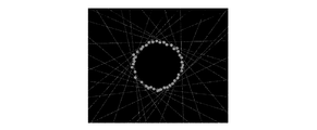
図42には、多方向からの計測イメージ図が示されており、各方向の全ての輪郭形状を重ねると図43のように任意水平面Z=Z1における断面形状が点群の曲線で計測できる。 FIG. 42 shows a measurement image diagram from multiple directions. When all the contour shapes in each direction are overlapped, the cross-sectional shape at an arbitrary horizontal plane Z = Z1 can be measured by a point cloud as shown in FIG.
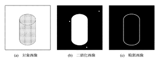
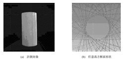
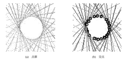
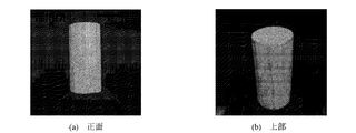
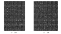
図44には、実際の計測の結果が示され、対象は円柱の木材であるが、図44(b)に示すとおり、円柱の断面形状点群で計測されているのが確認できる。 FIG. 44 shows the result of actual measurement, and the object is a cylindrical wood, but as shown in FIG. 44 (b), it can be confirmed that the measurement is performed with a cylindrical cross-sectional shape point group.
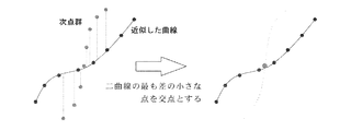
図44の輪郭形状は全てのシルエット画像から算出された点群曲線の集合データにしか過ぎず,各輪郭の座標は算出されていない.輪郭の座標を求めるために点群を近似曲線で表し,曲線と曲線の交点を求める。 The contour shape in FIG. 44 is only set data of point cloud curves calculated from all silhouette images, and the coordinates of each contour are not calculated. In order to obtain the coordinates of the contour, the point group is represented by an approximate curve, and the intersection of the curve and the curve is obtained.
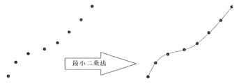
一つのシルエット画像から得られた候補点群に最小二乗法を行う事で近似曲線を求めることにより、N個の候補点の集合{(xi, yi)|i=1,2,…,N}が与えられた場合、点群は次式で近似することができる。
![]()
![]()
![]()
![]()
図45に曲線近似が示され、各交点は、近似した曲線とつぎのシルエット画像から得られた点群により求める。次点群全てに対し近似した曲線との差を算出し、差の最も少ない点を交点とする。 FIG. 45 shows curve approximation, and each intersection point is obtained from the approximated curve and a point group obtained from the next silhouette image. The difference from the approximated curve is calculated for all the next point groups, and the point with the smallest difference is taken as the intersection.
図47のように得られた点群について交点を求めていくことで、図43は対象形状の座標を得る事が出来る。図48は実際に計測を行った図44の点群に対し、交点を算出した結果であり、これにより、任意水平面における対象の断面形状を算出可能である。 FIG. 43 can obtain the coordinates of the target shape by obtaining the intersection point for the point group obtained as shown in FIG. FIG. 48 shows the result of calculating the intersection point with respect to the point group of FIG. 44 actually measured, whereby the cross-sectional shape of the object on an arbitrary horizontal plane can be calculated.
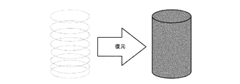
これにより、設定した任意の水平面Z=Z1における断面形状が算出され、つぎに設定した水平面Z=Z1を変更し、同じ計測を繰り返し、全ての結果から対象の形状を図49のように復元できることになる。 Thereby, the cross-sectional shape at the set arbitrary horizontal plane Z = Z1 is calculated, the next set horizontal plane Z = Z1 is changed, the same measurement is repeated, and the target shape can be restored from all the results as shown in FIG. become.
本実施例の場合、装置の精度評価を行うために大きさが既知である計測対象を50回計測し、任意に20回の結果によりRMS誤差を算出した。RMS誤差は系統的な対象となる値がその平均からどれだけ広い範囲に分布しているかを計算することで精度評価に用いられるものであり、
図50および図51はそれぞれ木材円柱の画像と計測結果であり、図51(b)のように本システムにより円柱の断面形状が正確に計測されている事がわかる。
本発明の実施例では、位置センサとして三次元磁気センサを利用しているが、これに限らずGPS位置情報取得装置を利用しても良い。前記撮像手段としてCCDカメラを利用しているが、CMOSセンサその他の画像取得センサを利用することは自由である。
FIG. 50 and FIG. 51 are respectively an image of a wood cylinder and measurement results, and it can be seen that the cross-sectional shape of the cylinder is accurately measured by this system as shown in FIG. 51 (b).
In the embodiment of the present invention, a three-dimensional magnetic sensor is used as the position sensor. However, the present invention is not limited to this, and a GPS position information acquisition device may be used. Although a CCD camera is used as the imaging means, it is free to use a CMOS sensor or other image acquisition sensor.
Claims (9)
体を含む領域のデータを取り出し、前記撮像手段を移動させて多方向からの画像取得
である撮影を行い、その結果を重ね、取り出した領域に水平面と平行な面を設定し、
その平面上で対象の断面形状を算出し、設定した水平面と平行な面の位置をその水平
を保ちながら上下方向に変えて算出を繰り返し行い、対象全体の形状を復元する請求
項6に記載の三次元形状計測・復元処理方法。 Perform image acquisition by a photographing said image pickup means from one direction of the object, retrieves the data of the area including an object to be measured, performs an image acquisition is captured from multiple directions by moving the imaging means, the Overlay the result, set a plane parallel to the horizontal plane in the extracted area,
The cross-sectional shape of the target is calculated on the plane, and the calculation is repeated by changing the position of the plane parallel to the set horizontal plane in the vertical direction while maintaining the level, and the shape of the entire target is restored. 3D shape measurement and restoration processing method.
The entire object is captured by the CCD camera, and simultaneously the position and orientation of the CCD camera are measured by a receiver that is a position sensor, and the obtained image is subjected to processing such as binarization and contour extraction to read the camera coordinates, The camera coordinates are converted into receiver coordinates based on the calibration data obtained in advance, and the receiver coordinates are converted into world coordinates based on the camera position and orientation at the time of shooting, and the camera is moved to capture the next silhouette. 7. The three-dimensional shape measurement according to claim 6, wherein after the measurement of all the contours is completed by performing the above-described processing repeatedly, the entire contour is displayed, the intersection is calculated, and the target shape is restored from all the results. -Restoration method.
Priority Applications (1)
| Application Number | Priority Date | Filing Date | Title |
|---|---|---|---|
| JP2004109920A JP2005292027A (en) | 2004-04-02 | 2004-04-02 | Processor and method for measuring/restoring three-dimensional shape |
Applications Claiming Priority (1)
| Application Number | Priority Date | Filing Date | Title |
|---|---|---|---|
| JP2004109920A JP2005292027A (en) | 2004-04-02 | 2004-04-02 | Processor and method for measuring/restoring three-dimensional shape |
Publications (1)
| Publication Number | Publication Date |
|---|---|
| JP2005292027A true JP2005292027A (en) | 2005-10-20 |
Family
ID=35325107
Family Applications (1)
| Application Number | Title | Priority Date | Filing Date |
|---|---|---|---|
| JP2004109920A Pending JP2005292027A (en) | 2004-04-02 | 2004-04-02 | Processor and method for measuring/restoring three-dimensional shape |
Country Status (1)
| Country | Link |
|---|---|
| JP (1) | JP2005292027A (en) |
Cited By (5)
| Publication number | Priority date | Publication date | Assignee | Title |
|---|---|---|---|---|
| JP2013514889A (en) * | 2009-12-22 | 2013-05-02 | コミッサリア ア レネルジ アトミック エ オー エネルジス アルテルナティヴス | Method for ablating a three-dimensional surface using a laser ablation device and through the use of a calibration step, and an apparatus for performing the method |
| CN108876933A (en) * | 2017-05-11 | 2018-11-23 | 富士施乐株式会社 | The method of the editing device and editor's three-dimensional shape data of three-dimensional shape data |
| JP2021085757A (en) * | 2019-11-27 | 2021-06-03 | 国立大学法人神戸大学 | Shape measuring method and device using focus image group by microscope |
| CN113223175A (en) * | 2021-05-12 | 2021-08-06 | 武汉中仪物联技术股份有限公司 | Method and system for constructing three-dimensional nonlinear model of pipeline based on true attitude angle |
| CN115752294A (en) * | 2022-11-22 | 2023-03-07 | 哈尔滨工业大学 | Method for measuring three-dimensional surface profile of large complex shaft of aero-engine |
Citations (6)
| Publication number | Priority date | Publication date | Assignee | Title |
|---|---|---|---|---|
| JPH05135155A (en) * | 1991-11-14 | 1993-06-01 | A T R Tsushin Syst Kenkyusho:Kk | Three-dimensional model constitution device using successive silhouette image |
| JPH11118438A (en) * | 1997-10-15 | 1999-04-30 | Matsushita Electric Ind Co Ltd | Method and device for measuring three-dimensional shape |
| JP2000346634A (en) * | 1999-06-09 | 2000-12-15 | Minolta Co Ltd | Three-dimensionally inputting device |
| JP2003203252A (en) * | 2001-10-26 | 2003-07-18 | Canon Inc | Image display device and its method and storage medium |
| JP2003216933A (en) * | 2002-01-28 | 2003-07-31 | Minolta Co Ltd | Data processing device, storage medium and program |
| JP2004062757A (en) * | 2002-07-31 | 2004-02-26 | Canon Inc | Image processing method and method for estimating imaging part position and attitude |
-
2004
- 2004-04-02 JP JP2004109920A patent/JP2005292027A/en active Pending
Patent Citations (6)
| Publication number | Priority date | Publication date | Assignee | Title |
|---|---|---|---|---|
| JPH05135155A (en) * | 1991-11-14 | 1993-06-01 | A T R Tsushin Syst Kenkyusho:Kk | Three-dimensional model constitution device using successive silhouette image |
| JPH11118438A (en) * | 1997-10-15 | 1999-04-30 | Matsushita Electric Ind Co Ltd | Method and device for measuring three-dimensional shape |
| JP2000346634A (en) * | 1999-06-09 | 2000-12-15 | Minolta Co Ltd | Three-dimensionally inputting device |
| JP2003203252A (en) * | 2001-10-26 | 2003-07-18 | Canon Inc | Image display device and its method and storage medium |
| JP2003216933A (en) * | 2002-01-28 | 2003-07-31 | Minolta Co Ltd | Data processing device, storage medium and program |
| JP2004062757A (en) * | 2002-07-31 | 2004-02-26 | Canon Inc | Image processing method and method for estimating imaging part position and attitude |
Cited By (8)
| Publication number | Priority date | Publication date | Assignee | Title |
|---|---|---|---|---|
| JP2013514889A (en) * | 2009-12-22 | 2013-05-02 | コミッサリア ア レネルジ アトミック エ オー エネルジス アルテルナティヴス | Method for ablating a three-dimensional surface using a laser ablation device and through the use of a calibration step, and an apparatus for performing the method |
| CN108876933A (en) * | 2017-05-11 | 2018-11-23 | 富士施乐株式会社 | The method of the editing device and editor's three-dimensional shape data of three-dimensional shape data |
| CN108876933B (en) * | 2017-05-11 | 2023-04-28 | 富士胶片商业创新有限公司 | Three-dimensional shape data editing device and method for editing three-dimensional shape data |
| JP2021085757A (en) * | 2019-11-27 | 2021-06-03 | 国立大学法人神戸大学 | Shape measuring method and device using focus image group by microscope |
| CN113223175A (en) * | 2021-05-12 | 2021-08-06 | 武汉中仪物联技术股份有限公司 | Method and system for constructing three-dimensional nonlinear model of pipeline based on true attitude angle |
| CN113223175B (en) * | 2021-05-12 | 2023-05-05 | 武汉中仪物联技术股份有限公司 | Pipeline three-dimensional nonlinear model construction method and system based on real attitude angle |
| CN115752294A (en) * | 2022-11-22 | 2023-03-07 | 哈尔滨工业大学 | Method for measuring three-dimensional surface profile of large complex shaft of aero-engine |
| CN115752294B (en) * | 2022-11-22 | 2024-01-23 | 哈尔滨工业大学 | Method for measuring three-dimensional surface profile of large complex shaft of aero-engine |
Similar Documents
| Publication | Publication Date | Title |
|---|---|---|
| CN111060023B (en) | High-precision 3D information acquisition equipment and method | |
| CN113379822B (en) | Method for acquiring 3D information of target object based on pose information of acquisition equipment | |
| GB2564794B (en) | Image-stitching for dimensioning | |
| JP5480914B2 (en) | Point cloud data processing device, point cloud data processing method, and point cloud data processing program | |
| JP6426968B2 (en) | INFORMATION PROCESSING APPARATUS AND METHOD THEREOF | |
| KR101604037B1 (en) | method of making three dimension model and defect analysis using camera and laser scanning | |
| JP5029618B2 (en) | Three-dimensional shape measuring apparatus, method and program by pattern projection method | |
| JP5587137B2 (en) | Measuring apparatus and measuring method | |
| CN112161619B (en) | Pose detection method, three-dimensional scanning path planning method and detection system | |
| CN107025663A (en) | It is used for clutter points-scoring system and method that 3D point cloud is matched in vision system | |
| CN107909624B (en) | Method for extracting and fusing two-dimensional image from three-dimensional tomography | |
| Hosseininaveh et al. | Towards fully automatic reliable 3D acquisition: From designing imaging network to a complete and accurate point cloud | |
| JP5463584B2 (en) | Displacement measuring method, displacement measuring apparatus, and displacement measuring program | |
| KR102109814B1 (en) | Apparatus and method for registering images | |
| Fernandez et al. | Planar-based camera-projector calibration | |
| JP2007508557A (en) | Device for scanning three-dimensional objects | |
| WO2020075252A1 (en) | Information processing device, program, and information processing method | |
| CN111445528B (en) | Multi-camera common calibration method in 3D modeling | |
| Hafeez et al. | Image based 3D reconstruction of texture-less objects for VR contents | |
| JP2005283440A (en) | Vibration measuring device and measuring method thereof | |
| Sun et al. | High-accuracy three-dimensional measurement based on multi-directional cooperative target with weighted SfM algorithm | |
| Siddique et al. | 3d object localization using 2d estimates for computer vision applications | |
| JP2005292027A (en) | Processor and method for measuring/restoring three-dimensional shape | |
| KR101673144B1 (en) | Stereoscopic image registration method based on a partial linear method | |
| JP7251631B2 (en) | Template creation device, object recognition processing device, template creation method, object recognition processing method, and program |
Legal Events
| Date | Code | Title | Description |
|---|---|---|---|
| A621 | Written request for application examination |
Free format text: JAPANESE INTERMEDIATE CODE: A621 Effective date: 20070316 |
|
| A977 | Report on retrieval |
Free format text: JAPANESE INTERMEDIATE CODE: A971007 Effective date: 20091008 |
|
| A131 | Notification of reasons for refusal |
Free format text: JAPANESE INTERMEDIATE CODE: A131 Effective date: 20091013 |
|
| A521 | Written amendment |
Free format text: JAPANESE INTERMEDIATE CODE: A523 Effective date: 20091209 |
|
| A131 | Notification of reasons for refusal |
Effective date: 20100112 Free format text: JAPANESE INTERMEDIATE CODE: A131 |
|
| A02 | Decision of refusal |
Effective date: 20100511 Free format text: JAPANESE INTERMEDIATE CODE: A02 |