JP2005292009A - Infrared gas detector and detection method - Google Patents
Infrared gas detector and detection method Download PDFInfo
- Publication number
- JP2005292009A JP2005292009A JP2004109379A JP2004109379A JP2005292009A JP 2005292009 A JP2005292009 A JP 2005292009A JP 2004109379 A JP2004109379 A JP 2004109379A JP 2004109379 A JP2004109379 A JP 2004109379A JP 2005292009 A JP2005292009 A JP 2005292009A
- Authority
- JP
- Japan
- Prior art keywords
- infrared
- gas
- detection signal
- measurement gas
- water vapor
- Prior art date
- Legal status (The legal status is an assumption and is not a legal conclusion. Google has not performed a legal analysis and makes no representation as to the accuracy of the status listed.)
- Pending
Links
- 238000001514 detection method Methods 0.000 title claims abstract description 86
- 238000005259 measurement Methods 0.000 claims abstract description 52
- 238000010521 absorption reaction Methods 0.000 claims abstract description 30
- XLYOFNOQVPJJNP-UHFFFAOYSA-N water Chemical compound O XLYOFNOQVPJJNP-UHFFFAOYSA-N 0.000 claims description 56
- 238000012545 processing Methods 0.000 abstract description 13
- 230000003287 optical effect Effects 0.000 description 20
- NJPPVKZQTLUDBO-UHFFFAOYSA-N novaluron Chemical compound C1=C(Cl)C(OC(F)(F)C(OC(F)(F)F)F)=CC=C1NC(=O)NC(=O)C1=C(F)C=CC=C1F NJPPVKZQTLUDBO-UHFFFAOYSA-N 0.000 description 8
- 238000000034 method Methods 0.000 description 7
- 230000005540 biological transmission Effects 0.000 description 6
- 238000002834 transmittance Methods 0.000 description 5
- 238000002835 absorbance Methods 0.000 description 4
- 230000007423 decrease Effects 0.000 description 4
- 230000006866 deterioration Effects 0.000 description 3
- 239000000853 adhesive Substances 0.000 description 2
- 230000001070 adhesive effect Effects 0.000 description 2
- 238000010586 diagram Methods 0.000 description 2
- 230000000694 effects Effects 0.000 description 2
- 238000012986 modification Methods 0.000 description 2
- 230000004048 modification Effects 0.000 description 2
- 230000035945 sensitivity Effects 0.000 description 2
- NPNPZTNLOVBDOC-UHFFFAOYSA-N 1,1-difluoroethane Chemical compound CC(F)F NPNPZTNLOVBDOC-UHFFFAOYSA-N 0.000 description 1
- 238000004891 communication Methods 0.000 description 1
- 238000005192 partition Methods 0.000 description 1
- 230000000149 penetrating effect Effects 0.000 description 1
- 230000035699 permeability Effects 0.000 description 1
- 239000012466 permeate Substances 0.000 description 1
- 238000012797 qualification Methods 0.000 description 1
- 239000004065 semiconductor Substances 0.000 description 1
- 239000000758 substrate Substances 0.000 description 1
Images
Classifications
-
- G—PHYSICS
- G01—MEASURING; TESTING
- G01N—INVESTIGATING OR ANALYSING MATERIALS BY DETERMINING THEIR CHEMICAL OR PHYSICAL PROPERTIES
- G01N21/00—Investigating or analysing materials by the use of optical means, i.e. using sub-millimetre waves, infrared, visible or ultraviolet light
- G01N21/17—Systems in which incident light is modified in accordance with the properties of the material investigated
- G01N21/25—Colour; Spectral properties, i.e. comparison of effect of material on the light at two or more different wavelengths or wavelength bands
- G01N21/31—Investigating relative effect of material at wavelengths characteristic of specific elements or molecules, e.g. atomic absorption spectrometry
- G01N21/35—Investigating relative effect of material at wavelengths characteristic of specific elements or molecules, e.g. atomic absorption spectrometry using infrared light
- G01N21/3554—Investigating relative effect of material at wavelengths characteristic of specific elements or molecules, e.g. atomic absorption spectrometry using infrared light for determining moisture content
Abstract
Description
本発明は、赤外線吸収波長が水蒸気と重複する測定ガスの濃度を検出する赤外線式ガス検出器及び検出方法に関するものである。 The present invention relates to an infrared gas detector and a detection method for detecting the concentration of a measurement gas whose infrared absorption wavelength overlaps with water vapor.
従来、例えば特許文献1に開示されるように、特定波長の赤外線を吸収し、赤外線吸収量に応じた検出信号を出力する検出部(赤外線センサ)を備え、当該検出信号に基づいて測定ガスの濃度を検出する赤外線式ガス検出器が知られている。 Conventionally, as disclosed in Patent Document 1, for example, a detection unit (infrared sensor) that absorbs infrared light of a specific wavelength and outputs a detection signal corresponding to the amount of infrared absorption is provided. Infrared gas detectors that detect concentration are known.
この赤外線式ガス検出器(非分散型赤外吸収式ガス分析装置)は、測定ガス中の複数のガス成分に対応して、所定の赤外線透過波長領域が設定された複数の定性用光学フィルタを有している。そして、試料セル内の測定ガスに照射され、上述の定性用光学フィルタを透過した赤外線量を赤外線センサにより検出する構成としている。 This infrared gas detector (non-dispersive infrared absorption gas analyzer) includes a plurality of qualitative optical filters in which a predetermined infrared transmission wavelength region is set corresponding to a plurality of gas components in a measurement gas. Have. And it is set as the structure which detects the amount of infrared rays irradiated to the measurement gas in a sample cell, and permeate | transmitted the above-mentioned qualitative optical filter with an infrared sensor.
例えば、COと水蒸気の共存下において、水蒸気濃度を検出する場合、COの干渉影響を受けないように赤外線透過波長領域が設定されたH20定性用光学フィルタを赤外線の光路上に配置し、赤外線センサの出力から水蒸気の濃度を検出する。
For example, when water vapor concentration is detected in the presence of CO and water vapor, an
また、CO濃度を検出する場合、COの吸光度が大きく、水蒸気の吸光度が比較的小さい赤外線透過波長領域が設定されたCO定性用光学フィルタを赤外線の光路上に配置し、赤外線センサの出力から水蒸気の干渉分を含むCO濃度を検出する。そして、水蒸気の干渉分を含むCO濃度から上述の水蒸気濃度に基づく水蒸気の干渉分を補正してCOの濃度を算出する。このように、赤外線吸収波長が水蒸気と重複する測定ガスの濃度を検出することができる。
しかしながら、上記構成の場合、H20定性用光学フィルタとCO定性用光学フィルタを赤外線の光路上に切り換えて配置する必要がある。実際、特許文献1において、H20定性用光学フィルタ及びCO定性用光学フィルタは、切換装置としてのモータにより回転駆動される赤外断続チョッパ上に180度間隔で配置され、赤外断続チョッパを連続的に回転させて両フィルタの切換を行う構成としている。また、赤外断続チョッパの回転位置(どちらのフィルタが赤外線の光路上にあるか)を検出するために、位置認識センサが設けられている。従って、赤外線式ガス検出器の体格を小型化するのが困難である。
However, in the case of the above configuration, it is necessary to switch the
本発明は上記問題点に鑑み、赤外線吸収波長が水蒸気と重複する測定ガスの濃度を精度良く検出でき、且つ、体格を小型化できる赤外線式ガス検出器及び検出方法を提供することを目的とする。 In view of the above problems, an object of the present invention is to provide an infrared gas detector and a detection method capable of accurately detecting the concentration of a measurement gas having an infrared absorption wavelength overlapping with water vapor and reducing the size of the measurement gas. .
上記目的を達成する為に請求項1に記載の発明は、特定波長の赤外線を吸収し、赤外線吸収量に応じた検出信号を出力する検出部を備え、検出信号に基づいて、赤外線吸収波長が水蒸気と重複する測定ガスの濃度を検出する赤外線式ガス検出器に関するものである。そして、測定ガスと共存し、赤外線を一部吸収する水蒸気の絶対湿度を検出する湿度検出部をさらに備え、検出された絶対湿度に基づいて検出信号を補正し、補正された検出信号に基づいて測定ガスの濃度を検出する構成としたことを特徴とする。 In order to achieve the above object, the invention described in claim 1 includes a detection unit that absorbs infrared light of a specific wavelength and outputs a detection signal corresponding to the amount of infrared absorption, and the infrared absorption wavelength is based on the detection signal. The present invention relates to an infrared gas detector that detects the concentration of a measurement gas overlapping with water vapor. Further, the apparatus further comprises a humidity detection unit that detects the absolute humidity of water vapor that coexists with the measurement gas and partially absorbs infrared rays, corrects the detection signal based on the detected absolute humidity, and based on the corrected detection signal A feature is that the concentration of the measurement gas is detected.
このように、本発明の赤外線式ガス検出器によると、湿度検出部によって絶対湿度を検出することができる。従って、絶対湿度が分かれば、所定の赤外線波長における水蒸気の赤外線吸収量が分かるので、水蒸気の干渉分を含む検出信号から水蒸気の干渉分を補正し、測定ガスの濃度を精度良く検出することができる。また、湿度検出部を新たに備えるものの、複数の定性用光学フィルタ、切換装置、及び位置認識センサが不要であるので、従来よりも体格を小型化することができる。 Thus, according to the infrared gas detector of the present invention, the absolute humidity can be detected by the humidity detector. Therefore, if the absolute humidity is known, the infrared absorption amount of water vapor at a predetermined infrared wavelength can be known, so that the water vapor interference can be corrected from the detection signal including the water vapor interference to accurately detect the concentration of the measurement gas. it can. Moreover, although a humidity detection part is newly provided, since a plurality of qualitative optical filters, a switching device, and a position recognition sensor are unnecessary, the physique can be made smaller than before.
尚、湿度検出部としては、直接的に水蒸気の絶対湿度を検出するものだけでなく、間接的に水蒸気の絶対湿度を検出することができるものも適用することができる。例えば、相対湿度を検出する湿度センサや露点計等を温度センサとともに適用する構成としても良い。 In addition, as a humidity detection part, not only what detects the absolute humidity of water vapor | steam directly but what can detect the absolute humidity of water vapor | steam indirectly is applicable. For example, a configuration in which a humidity sensor that detects relative humidity, a dew point meter, or the like is applied together with the temperature sensor may be employed.
尚、赤外線式ガス検出器は、抵抗体を発熱させることにより赤外線を放射する光源部を別個に備えても良いし、請求項2に記載のように一体に備えても良い。 The infrared gas detector may include a light source unit that emits infrared rays by generating heat from the resistor, or may be provided integrally as described in claim 2.
請求項3に記載のように、測定ガス及び水蒸気のいずれの赤外線吸収波長とも重複しない所定波長の赤外線を吸収し、赤外線吸収量に応じた参照信号を出力する参照部をさらに備え、参照信号に基づいて検出信号を補正し、補正された検出信号に基づいて測定ガスの濃度を検出する構成としても良い。この場合、例えば光源部の劣化により、検出部が受光する赤外線量が低下しても、参照信号に基づいて検出信号を補正することにより、センサ感度の低下を防ぐことができる。 According to a third aspect of the present invention, the apparatus further includes a reference unit that absorbs infrared light having a predetermined wavelength that does not overlap with any infrared absorption wavelength of the measurement gas and water vapor, and outputs a reference signal corresponding to the amount of infrared absorption. The detection signal may be corrected based on the detection gas, and the concentration of the measurement gas may be detected based on the corrected detection signal. In this case, for example, even if the amount of infrared light received by the detection unit decreases due to deterioration of the light source unit, it is possible to prevent a decrease in sensor sensitivity by correcting the detection signal based on the reference signal.
その際、赤外線を吸収する検出部と参照部とを異なるパッケージに配置した構成としても良いが、請求項4に記載のように、同一の光源部からの赤外線を受光するように、検出部及び参照部を同一のパッケージ内に配置した構成としても良い。この場合、光源部に対する赤外線式ガス検出器毎の検出部及び参照部の位置のばらつきを低減でき、一方だけ外部雰囲気等の影響を強く受けることはないので、参照信号に基づいて検出信号を精度よく補正することができる。また、赤外線式ガス検出器の体格を小型化できる。尚、上記光源部は赤外線式ガス検出器として一体化されていても良いし、別個に設けられていても良い。 In this case, the detection unit that absorbs infrared rays and the reference unit may be arranged in different packages. However, as described in claim 4, the detection unit and the reference unit are configured to receive infrared rays from the same light source unit. It is good also as a structure which has arrange | positioned the reference part in the same package. In this case, variation in the position of the detection unit and reference unit for each infrared gas detector with respect to the light source unit can be reduced, and only one of them is not strongly influenced by the external atmosphere, so the detection signal is accurate based on the reference signal. It can be corrected well. In addition, the size of the infrared gas detector can be reduced. In addition, the said light source part may be integrated as an infrared type gas detector, and may be provided separately.
請求項5又は請求項6に記載の赤外線式ガス検出方法の作用効果は、請求項1又は請求項3に記載の赤外線式ガス検出器の作用効果と同様であるので、その記載を省略する。 Since the operational effects of the infrared gas detection method according to claim 5 or 6 are the same as the operational effects of the infrared gas detector according to claim 1 or 3, the description thereof is omitted.
以下、本発明の実施の形態を、図に基づいて説明する。 Hereinafter, embodiments of the present invention will be described with reference to the drawings.
(第1の実施形態)
図1は、本実施形態における赤外線式ガス検出器の概略構成を示す図である。
(First embodiment)
FIG. 1 is a diagram showing a schematic configuration of an infrared gas detector in the present embodiment.
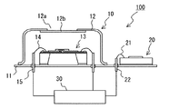
図1に示すように、赤外線式ガス検出器100は、特定波長の赤外線を検出する検出部10と、測定ガスと共存し、上記赤外線を一部吸収する水蒸気の絶対湿度を検出する湿度検出部20と、各検出部10,20からの信号を処理する処理部30とにより構成される。
As shown in FIG. 1, the
検出部10は、基部となる台座11と、台座11に取り付けられるキャップ12と、台座11及びキャップ12から構成される内部空間に配置された赤外線センサ13とを備えている。
The
キャップ12は、赤外線光源から放射される赤外線の透過波長、及び、赤外線センサ13に対する入射領域を制限するものであり、入射窓部12aを除く部位は赤外線を遮蔽するように構成されている。この入射窓部12aは、赤外線センサ13に対応する位置に設けられており、当該入射窓部12aには特定波長の赤外線(測定ガスの赤外線吸収波長帯に合わせた)のみを選択的に透過させるバンドパスフィルタ12bが設置されている。
The
赤外線センサ13は、台座11上に例えば接着剤を介して固定されており、キャップ12のバンドパスフィルタ12bを透過する特定波長の赤外線のみを吸収し、その赤外線吸収量に応じた検出信号を後述する処理部30に出力するように構成されている。尚、図1において、赤外線センサ13は、ボンディングワイヤ14を介して、台座11に貫通しつつ固定された外部出力端子としてのターミナル15に電気的に接続されており、赤外線センサ13は処理部30と電気的に接続されている。
The
ここで、赤外線センサ13としては特に限定されるものではなく、例えばサーモパイル型、ボロメータ型、焦電型等を適用することができる。本実施形態においては、一般的な半導体プロセスで形成することができるサーモパイル型の赤外線センサ13を適用している。尚、赤外線センサ13の構成については、本発明の特徴部分ではなく、例えば本出願人が先に特開2002−365140号広報等により開示しているので、本実施形態における詳細な説明は省略する。
Here, the
湿度検出部20は、測定ガスと共存する水蒸気による絶対湿度(単位体積(1m3)の気体中に含まれる水蒸気の質量(g))を検出するためのものであり、本実施形態においては赤外線センサ13が固定されている台座11の同一平面に固定されている。
The
湿度検出部20としては、直接的に絶対湿度を検出する構成のものだけでなく、間接的に絶対湿度を検出する構成のものも適用することができる。例えば、相対湿度を検出する湿度センサや露点計等を温度センサとともに適用し、演算処理により絶対湿度を算出する構成のものでも良い。尚、図1において、湿度検出部20は、ボンディングワイヤ21を介して、台座11に貫通しつつ固定された外部出力端子としてのターミナル22に電気的に接続されており、赤外線センサ20は処理部30と電気的に接続されている。
As the
処理部30は、検出部10を構成する赤外線センサ13からの検出信号と、湿度検出部20からの信号を受けて、所定の演算処理を実行し、水蒸気の干渉分を含む赤外線センサ13の検出信号から水蒸気の干渉分を補正処理し、赤外線吸収波長が水蒸気と重複する測定ガスの濃度を算出する。尚、測定ガスの濃度検出の詳細については後述する。
The
次に、上記構成の赤外線式ガス検出器100における測定ガスの濃度検出方法について、図2及び図3を用いて説明する。
Next, a method for detecting the concentration of the measurement gas in the
通常、測定ガス(例えばHFC−152a)の濃度を検出する場合、当該測定ガスの赤外線吸収波長の少なくとも一部が水蒸気と重複し、赤外線の一部が水蒸気によっても吸収されるので、赤外線センサの出力は水蒸気の干渉分を含む出力となる。すなわち、このままでは測定ガスの濃度を精度よく検出することができない。 Usually, when detecting the concentration of a measurement gas (for example, HFC-152a), at least part of the infrared absorption wavelength of the measurement gas overlaps with water vapor, and part of infrared light is also absorbed by water vapor. The output is an output including the interference of water vapor. That is, the concentration of the measurement gas cannot be detected with high accuracy as it is.
それを解決する方法として、例えば以下の方法が提案されている。測定ガスの干渉影響を受けないように赤外線透過波長領域が設定されたH20定性用光学フィルタを赤外線の光路上に配置し、赤外線センサの出力から水蒸気の濃度を検出する。次に、測定ガスの吸光度が大きく、水蒸気の吸光度が比較的小さい赤外線透過波長領域が設定された測定ガス定性用光学フィルタを赤外線の光路上に配置し、赤外線センサの出力から水蒸気の干渉分を含む測定ガスの濃度を検出する。そして、水蒸気の干渉分を含む測定ガスの濃度から上述の水蒸気濃度に基づく水蒸気の干渉分を補正して測定ガスの濃度を算出する。
As a method for solving this problem, for example, the following method has been proposed. An
しかしながら、この方法の場合、複数のフィルタが必要である。また、H20定性用光学フィルタと測定ガス定性用光学フィルタを赤外線センサに対する赤外線の光路上に切り換て配置するための切換装置が必要である。さらには、赤外線センサからの信号がどちらのフィルタを通過した際の信号なのかを判断するための位置認識装置が必要である。従って、赤外線式ガス検出器の体格を小型化するのが困難である。
However, this method requires multiple filters. Further, a switching device for switching the
それに対し、本実施形態における赤外線式ガス検出器100は、赤外線センサ13の検出信号から水蒸気の干渉分を補正するために、絶対湿度を検出する湿度検出部20を有している。
On the other hand, the
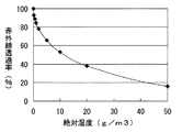
ここで、絶対湿度と赤外線透過率(水蒸気による)との関係は、例えば久野治義著、“赤外線光学”、社団法人電子情報通信学会、平成10年5月20日発行、p58〜59に記載されている。その一例を図2に示す。尚、図2において、赤外線の波長は3.3μmである。 Here, the relationship between absolute humidity and infrared transmittance (due to water vapor) is described in, for example, Osamu Kuno, “Infrared Optics”, The Institute of Electronics, Information and Communication Engineers, May 20, 1998, p. ing. An example is shown in FIG. In FIG. 2, the wavelength of infrared rays is 3.3 μm.
すなわち、湿度検出部20により絶対湿度を検出することで、所定の赤外線波長における水蒸気の赤外線吸収率(赤外線透過率)を算出し、水蒸気の干渉分を含む赤外線センサ13の検出信号から、水蒸気の干渉分を補正することができ、赤外線吸収波長が水蒸気と重複する測定ガスの濃度を精度良く検出することができる。
That is, by detecting the absolute humidity by the
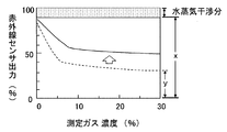
測定ガスの濃度の算出方法としては、例えば絶対湿度から求められる水蒸気の赤外線透過率(%)をx、赤外線センサ13にて検出された水蒸気の干渉分を含む検出信号(センサ出力)をyとすると、測定ガスのセンサ出力を下記式で示すことができる。
(式1)測定ガスのセンサ出力(%)=y×100/x
尚、図3において数式1の関係を示している。図3において、ハッチング部分が水蒸気による干渉分(100−x)を、破線が赤外線センサ13にて検出された水蒸気の干渉分を含むセンサ出力yを、実線が水蒸気の干渉分を補正した測定ガスのセンサ出力を示している。
As a method for calculating the concentration of the measurement gas, for example, the infrared transmittance (%) of water vapor obtained from absolute humidity is x, and the detection signal (sensor output) including the interference of water vapor detected by the
(Expression 1) Sensor output of measurement gas (%) = y × 100 / x
In addition, in FIG. 3, the relationship of Formula 1 is shown. In FIG. 3, the hatched portion indicates the interference caused by water vapor (100−x), the broken line indicates the sensor output y including the water vapor interference detected by the
本実施形態においては、湿度検出部20からの絶対湿度信号を受けた処理部30としての回路チップが、絶対湿度から水蒸気の赤外線透過率xを算出し、上記数式1の演算を実行して、測定ガスのセンサ出力を外部に出力する構成としている。
In the present embodiment, the circuit chip as the
このように、本実施形態における赤外線式ガス検出器100及び赤外線式ガス検出方法によると、湿度検出部20により絶対湿度を検出することができるので、水蒸気の干渉分を含む赤外線センサ13の検出信号から水蒸気の干渉分を補正することができる。すなわち、赤外線吸収波長が水蒸気と重複する測定ガスの濃度を精度良く検出することができる。
As described above, according to the
また、湿度検出部20を新たに備えるものの、上述のように複数の定性用光学フィルタ、切換装置、及び位置認識装置が不要であるので、従来よりも体格を小型化することができる。
Further, although the
以上本発明の好ましい実施形態について説明したが、本発明は上述の実施形態のみに限定されず、種々変更して実施する事ができる。 The preferred embodiments of the present invention have been described above. However, the present invention is not limited to the above-described embodiments, and various modifications can be made.
本実施形態においては図示していないが、処理部30とは別個に、赤外線センサ13及び/又は湿度検出部20に信号処理用の回路チップを配置した構成としても良い。
Although not shown in the present embodiment, a signal processing circuit chip may be arranged in the
また、本実施形態においては、赤外線センサ13(検出部10)の検出信号を湿度検出部20により検出した絶対湿度に基づいて補正する例を示した。しかしながら、赤外線式ガス検出器100が、さらに測定ガス及び水蒸気のいずれの赤外線吸収波長とも重複しない所定波長の赤外線を吸収し、赤外線吸収量に応じた参照信号を出力する参照部を備え、参照信号に基づいて赤外線センサ13の検出信号をさらに補正する構成としても良い。
Moreover, in this embodiment, the example which correct | amends the detection signal of the infrared sensor 13 (detection part 10) based on the absolute humidity detected by the
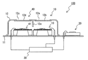
参照部を備える赤外線式ガス検出器100の構成例を図4に示す。図4において、参照部40は検出部10と一体に構成されており、検出部10を構成する台座11とキャップ12からなる内部空間に、受光した赤外線量に応じた検出信号(参照信号)を出力する参照用赤外線センサ41が、赤外線センサ13と並んで配置されている。また、キャップ12には、参照用赤外線センサ41に対応する位置に参照用入射窓部12cが設けられ、当該参照用入射窓部12cに、特定波長の赤外線(測定ガス及び水蒸気のいずれの赤外線吸収波長とも重複しない)のみを選択的に透過させる参照用バンドパスフィルタ12dが設置されている。さらに、キャップ12には、各バンドパスフィルタ12b,12dを透過した赤外線が、対応しない赤外線センサ13,41側へ入射するのを防ぐために、上部から台座11側に向けて伸延する隔壁12eが設けられている。そして、参照用赤外線センサ41が、台座11上に例えば接着剤を介して固定されており、キャップ12の参照用バンドパスフィルタ12dを透過する特定波長の赤外線のみを吸収し、その赤外線吸収量に応じた参照信号を処理部30に出力するように構成されている。
A configuration example of the
このように、参照部40から出力される参照信号は測定ガス及び水蒸気の影響を受けない。従って、参照部40が出力する初期の参照信号(赤外線受光量にもとづく参照用赤外線センサ41のセンサ出力)を基準出力とし、赤外線光源の劣化により低下した参照信号を乗算して基準出力に補正する際の係数を用いて、検出部10の検出信号を補正する。これにより、同一の赤外線光源の劣化により検出部10が受光する赤外線量が低下しても、センサ感度の低下を防ぐことができる。
Thus, the reference signal output from the
また、図4に示すように、検出部10及び参照部40を同一のキャップ12内に配置した構成とすると、赤外線光源に対する赤外線式ガス検出器100毎の検出部10及び参照部40の位置のばらつきを低減できる。また、検出部10及び参照部40のいずれか一方だけ外部雰囲気(温度等)の影響を強く受けることはないので、参照信号に基づいて検出信号を精度よく補正することができる。さらには、赤外線式ガス検出器100の体格を小型化できる。しかしながら、参照部40は、上記図4の構成に限定されるものではない。例えば、赤外線センサ13と参照用赤外線センサ41が同一基板を用いて形成されても良い。また、異なる内部空間(異なるキャップ12と台座11からなる)に赤外線センサ13と参照用赤外線センサ41がそれぞれ配置されても良い。
As shown in FIG. 4, when the
また、本実施形態においては、赤外線式ガス検出器100が通電することにより抵抗体を発熱させて赤外線を放射する光源部(赤外線光源)を一体に有していない例を示した。しかしながら、光源部を一体に備える構成としても良い。
Moreover, in this embodiment, the
また、本実施形態において、湿度検出部20は、赤外線センサ13と同一の台座11に固定されている例を示した。しかしながら、湿度検出部20の配置は本実施形態に限定されるものではない。
Moreover, in this embodiment, the
10・・・検出部
11・・・台座
12・・・キャップ
12b・・・バンドパスフィルタ
13・・・赤外線センサ
20・・・湿度検出部
30・・・処理部(回路チップ)
40・・・参照部
41・・・参照用赤外線センサ
100・・・赤外線式ガス検出器
DESCRIPTION OF
40 ...
Claims (6)
前記検出信号に基づいて、赤外線吸収波長が水蒸気と重複する測定ガスの濃度を検出する赤外線式ガス検出器において、
前記測定ガスと共存し、前記赤外線を一部吸収する前記水蒸気の絶対湿度を検出する湿度検出部をさらに備え、
検出された前記絶対湿度に基づいて前記検出信号を補正し、補正された前記検出信号に基づいて前記測定ガスの濃度を検出する構成としたことを特徴とする赤外線式ガス検出器。 It has a detection unit that absorbs infrared light of a specific wavelength and outputs a detection signal according to the amount of infrared absorption,
In the infrared type gas detector that detects the concentration of the measurement gas whose infrared absorption wavelength overlaps with water vapor based on the detection signal,
A humidity detector that detects the absolute humidity of the water vapor that coexists with the measurement gas and partially absorbs the infrared rays;
An infrared gas detector, wherein the detection signal is corrected based on the detected absolute humidity, and the concentration of the measurement gas is detected based on the corrected detection signal.
前記参照信号に基づいて前記検出信号を補正し、補正された前記検出信号に基づいて前記測定ガスの濃度を検出する構成としたことを特徴とする請求項1に記載の赤外線式ガス検出器。 It further includes a reference unit that absorbs infrared light of a predetermined wavelength that does not overlap with any of the infrared absorption wavelengths of the measurement gas and the water vapor, and outputs a reference signal according to the amount of infrared absorption,
The infrared gas detector according to claim 1, wherein the detection signal is corrected based on the reference signal, and the concentration of the measurement gas is detected based on the corrected detection signal.
前記検出信号に基づいて測定ガスの濃度を検出する赤外線式ガス検出方法であって、
前記測定ガスと共存し、前記赤外線を一部吸収する前記水蒸気の絶対湿度を検出することにより、検出された前記絶対湿度に基づいて前記検出信号を補正し、補正された前記検出信号に基づいて前記測定ガスの濃度を検出することを特徴とする赤外線式ガス検出方法。 It has a detection unit that absorbs infrared light of a specific wavelength and outputs a detection signal according to the amount of infrared absorption,
An infrared gas detection method for detecting a concentration of a measurement gas based on the detection signal,
By detecting the absolute humidity of the water vapor that coexists with the measurement gas and partially absorbs the infrared light, the detection signal is corrected based on the detected absolute humidity, and based on the corrected detection signal An infrared gas detection method, wherein the concentration of the measurement gas is detected.
Priority Applications (3)
| Application Number | Priority Date | Filing Date | Title |
|---|---|---|---|
| JP2004109379A JP2005292009A (en) | 2004-04-01 | 2004-04-01 | Infrared gas detector and detection method |
| DE200510014186 DE102005014186A1 (en) | 2004-04-01 | 2005-03-29 | Infrared gas detector and method of using same |
| US11/095,468 US7288766B2 (en) | 2004-04-01 | 2005-04-01 | Infrared gas detector and method of the same |
Applications Claiming Priority (1)
| Application Number | Priority Date | Filing Date | Title |
|---|---|---|---|
| JP2004109379A JP2005292009A (en) | 2004-04-01 | 2004-04-01 | Infrared gas detector and detection method |
Publications (1)
| Publication Number | Publication Date |
|---|---|
| JP2005292009A true JP2005292009A (en) | 2005-10-20 |
Family
ID=35034283
Family Applications (1)
| Application Number | Title | Priority Date | Filing Date |
|---|---|---|---|
| JP2004109379A Pending JP2005292009A (en) | 2004-04-01 | 2004-04-01 | Infrared gas detector and detection method |
Country Status (3)
| Country | Link |
|---|---|
| US (1) | US7288766B2 (en) |
| JP (1) | JP2005292009A (en) |
| DE (1) | DE102005014186A1 (en) |
Cited By (5)
| Publication number | Priority date | Publication date | Assignee | Title |
|---|---|---|---|---|
| KR101034647B1 (en) | 2008-09-30 | 2011-05-16 | (주)유우일렉트로닉스 | High sensitive infrared detector for ndir type gas sensor using wafer level packaging and its manufacturing method |
| JP2014074629A (en) * | 2012-10-03 | 2014-04-24 | Chino Corp | Gas sensor |
| KR20150145951A (en) * | 2014-06-20 | 2015-12-31 | (주)야긴스텍 | Sensing system for gas leakage |
| JP2018116202A (en) * | 2017-01-20 | 2018-07-26 | 京セラドキュメントソリューションズ株式会社 | Integrated sensor and image forming device including the same |
| WO2019008925A1 (en) * | 2017-07-07 | 2019-01-10 | Phcホールディングス株式会社 | Gas sensor and constant-temperature device |
Families Citing this family (11)
| Publication number | Priority date | Publication date | Assignee | Title |
|---|---|---|---|---|
| US7807972B2 (en) * | 2005-01-26 | 2010-10-05 | Analog Devices, Inc. | Radiation sensor with cap and optical elements |
| US8487260B2 (en) * | 2005-01-26 | 2013-07-16 | Analog Devices, Inc. | Sensor |
| US8523427B2 (en) | 2008-02-27 | 2013-09-03 | Analog Devices, Inc. | Sensor device with improved sensitivity to temperature variation in a semiconductor substrate |
| US7996159B2 (en) * | 2008-09-10 | 2011-08-09 | Delphian Corporation | Gas detector system and method |
| JP2011128140A (en) * | 2009-11-19 | 2011-06-30 | Dainippon Printing Co Ltd | Sensor device and method of manufacturing the same |
| CN105122038B (en) | 2013-01-17 | 2018-09-07 | 探测器电子公司 | open path gas detector |
| WO2016141155A1 (en) | 2015-03-05 | 2016-09-09 | Honeywell International Inc. | Use of selected glass types and glass thicknesses in the optical path to remove cross sensitivity to water absorption peaks |
| EP3347697A1 (en) | 2015-09-10 | 2018-07-18 | Honeywell International Inc. | Gas detector with normalized response and improved sensitivity |
| WO2017062626A1 (en) | 2015-10-09 | 2017-04-13 | Honeywell International Inc. | Electromagnetic radiation detector using a planar golay cell |
| CN106370614A (en) * | 2016-08-15 | 2017-02-01 | 长春理工大学 | Multisectional infrared-band gas detection apparatus and method |
| WO2021055221A1 (en) | 2019-09-18 | 2021-03-25 | Carrier Corporation | Heated gas detector for a transpotation refrigeration unit |
Family Cites Families (9)
| Publication number | Priority date | Publication date | Assignee | Title |
|---|---|---|---|---|
| US3790797A (en) * | 1971-09-07 | 1974-02-05 | S Sternberg | Method and system for the infrared analysis of gases |
| US4355233A (en) * | 1979-02-22 | 1982-10-19 | Beckman Instruments, Inc. | Method and apparatus for negating measurement effects of interferent gases in non-dispersive infrared analyzers |
| US5041723A (en) * | 1989-09-30 | 1991-08-20 | Horiba, Ltd. | Infrared ray detector with multiple optical filters |
| US5468961A (en) * | 1991-10-08 | 1995-11-21 | Fisher & Paykel Limited | Infrared gas analyser and humidity sensor |
| US5591975A (en) * | 1993-09-10 | 1997-01-07 | Santa Barbara Research Center | Optical sensing apparatus for remotely measuring exhaust gas composition of moving motor vehicles |
| US5418366A (en) * | 1994-05-05 | 1995-05-23 | Santa Barbara Research Center | IR-based nitric oxide sensor having water vapor compensation |
| US5886348A (en) * | 1997-02-14 | 1999-03-23 | American Intell-Sensors Corporation | Non-dispersive infrared gas analyzer with interfering gas correction |
| US20020026822A1 (en) * | 2000-07-26 | 2002-03-07 | Reading Andrew R. | Vehicle gas emission sampling and analysis assembly |
| JP2003050203A (en) | 2001-08-03 | 2003-02-21 | Nissan Motor Co Ltd | Gas analyzing device of non-dispersive infrared absorption type, and its analyzing method |
-
2004
- 2004-04-01 JP JP2004109379A patent/JP2005292009A/en active Pending
-
2005
- 2005-03-29 DE DE200510014186 patent/DE102005014186A1/en not_active Withdrawn
- 2005-04-01 US US11/095,468 patent/US7288766B2/en not_active Expired - Fee Related
Cited By (7)
| Publication number | Priority date | Publication date | Assignee | Title |
|---|---|---|---|---|
| KR101034647B1 (en) | 2008-09-30 | 2011-05-16 | (주)유우일렉트로닉스 | High sensitive infrared detector for ndir type gas sensor using wafer level packaging and its manufacturing method |
| JP2014074629A (en) * | 2012-10-03 | 2014-04-24 | Chino Corp | Gas sensor |
| KR20150145951A (en) * | 2014-06-20 | 2015-12-31 | (주)야긴스텍 | Sensing system for gas leakage |
| KR101598280B1 (en) * | 2014-06-20 | 2016-02-29 | (주)야긴스텍 | Sensing system for gas leakage |
| JP2018116202A (en) * | 2017-01-20 | 2018-07-26 | 京セラドキュメントソリューションズ株式会社 | Integrated sensor and image forming device including the same |
| WO2019008925A1 (en) * | 2017-07-07 | 2019-01-10 | Phcホールディングス株式会社 | Gas sensor and constant-temperature device |
| JPWO2019008925A1 (en) * | 2017-07-07 | 2020-01-09 | Phcホールディングス株式会社 | Gas sensor and constant temperature device |
Also Published As
| Publication number | Publication date |
|---|---|
| US7288766B2 (en) | 2007-10-30 |
| DE102005014186A1 (en) | 2005-10-20 |
| US20050218327A1 (en) | 2005-10-06 |
Similar Documents
| Publication | Publication Date | Title |
|---|---|---|
| US7288766B2 (en) | Infrared gas detector and method of the same | |
| US8467051B2 (en) | Widely-tunable semiconductor source integrated in windowed hermetic package | |
| KR101837073B1 (en) | Integrated ir source and acoustic detector for photoacoustic gas sensor | |
| JP5959509B2 (en) | Measuring unit and gas analyzer | |
| US9546950B2 (en) | Optical gas sensing apparatus with explosion-proof enclosure | |
| CN104903704A (en) | Tunable diode laser absorption spectroscopy with water vapor determination | |
| US20010015408A1 (en) | Infrared optical gas-measuring device and gas-measuring process | |
| JPH07151684A (en) | Infrared ray type gas analyzer | |
| JP2013096889A (en) | Infrared gas analyzer | |
| US8661874B2 (en) | Photoacoustic detector with background signal correction | |
| JP2009257808A (en) | Infrared gas analyzer | |
| KR100910871B1 (en) | Method and apparatus for measuring water contained in the chimney gas | |
| JP2006038721A (en) | Gas concentration detector | |
| JP2004294214A (en) | Gas detecting device | |
| US10996201B2 (en) | Photoacoustic measurement systems and methods using the photoacoustic effect to measure emission intensities, gas concentrations, and distances | |
| JPH06249779A (en) | Gas analyzer | |
| JP2022151664A (en) | gas sensor | |
| JP4790330B2 (en) | Gas concentration measuring device | |
| US8729475B1 (en) | Absorption biased single beam NDIR gas sensor | |
| EP3726200A1 (en) | Particle sensor | |
| JP2017032317A (en) | Gas concentration measurement device | |
| JP2013185996A (en) | Nondispersive infrared analyzer type gas detector | |
| JP2004053432A (en) | Infrared gas analyzer | |
| JPH0210441Y2 (en) | ||
| JPH0560687A (en) | Infrared analyzer |
Legal Events
| Date | Code | Title | Description |
|---|---|---|---|
| A621 | Written request for application examination |
Free format text: JAPANESE INTERMEDIATE CODE: A621 Effective date: 20060621 |
|
| A977 | Report on retrieval |
Free format text: JAPANESE INTERMEDIATE CODE: A971007 Effective date: 20080118 |
|
| A131 | Notification of reasons for refusal |
Free format text: JAPANESE INTERMEDIATE CODE: A131 Effective date: 20080212 |
|
| A521 | Written amendment |
Free format text: JAPANESE INTERMEDIATE CODE: A523 Effective date: 20080410 |
|
| A521 | Written amendment |
Free format text: JAPANESE INTERMEDIATE CODE: A523 Effective date: 20080422 |
|
| A02 | Decision of refusal |
Free format text: JAPANESE INTERMEDIATE CODE: A02 Effective date: 20080617 |