JP2005291789A - Distance detecting apparatus - Google Patents
Distance detecting apparatus Download PDFInfo
- Publication number
- JP2005291789A JP2005291789A JP2004104121A JP2004104121A JP2005291789A JP 2005291789 A JP2005291789 A JP 2005291789A JP 2004104121 A JP2004104121 A JP 2004104121A JP 2004104121 A JP2004104121 A JP 2004104121A JP 2005291789 A JP2005291789 A JP 2005291789A
- Authority
- JP
- Japan
- Prior art keywords
- case
- electromagnetic wave
- window part
- projection window
- distance
- Prior art date
- Legal status (The legal status is an assumption and is not a legal conclusion. Google has not performed a legal analysis and makes no representation as to the accuracy of the status listed.)
- Pending
Links
Images
Classifications
-
- G—PHYSICS
- G02—OPTICS
- G02B—OPTICAL ELEMENTS, SYSTEMS OR APPARATUS
- G02B26/00—Optical devices or arrangements for the control of light using movable or deformable optical elements
- G02B26/08—Optical devices or arrangements for the control of light using movable or deformable optical elements for controlling the direction of light
- G02B26/10—Scanning systems
- G02B26/12—Scanning systems using multifaceted mirrors
-
- G—PHYSICS
- G01—MEASURING; TESTING
- G01S—RADIO DIRECTION-FINDING; RADIO NAVIGATION; DETERMINING DISTANCE OR VELOCITY BY USE OF RADIO WAVES; LOCATING OR PRESENCE-DETECTING BY USE OF THE REFLECTION OR RERADIATION OF RADIO WAVES; ANALOGOUS ARRANGEMENTS USING OTHER WAVES
- G01S7/00—Details of systems according to groups G01S13/00, G01S15/00, G01S17/00
- G01S7/48—Details of systems according to groups G01S13/00, G01S15/00, G01S17/00 of systems according to group G01S17/00
- G01S7/481—Constructional features, e.g. arrangements of optical elements
- G01S7/4811—Constructional features, e.g. arrangements of optical elements common to transmitter and receiver
- G01S7/4813—Housing arrangements
-
- G—PHYSICS
- G02—OPTICS
- G02B—OPTICAL ELEMENTS, SYSTEMS OR APPARATUS
- G02B5/00—Optical elements other than lenses
- G02B5/08—Mirrors
- G02B5/09—Multifaceted or polygonal mirrors, e.g. polygonal scanning mirrors; Fresnel mirrors
-
- G—PHYSICS
- G01—MEASURING; TESTING
- G01S—RADIO DIRECTION-FINDING; RADIO NAVIGATION; DETERMINING DISTANCE OR VELOCITY BY USE OF RADIO WAVES; LOCATING OR PRESENCE-DETECTING BY USE OF THE REFLECTION OR RERADIATION OF RADIO WAVES; ANALOGOUS ARRANGEMENTS USING OTHER WAVES
- G01S17/00—Systems using the reflection or reradiation of electromagnetic waves other than radio waves, e.g. lidar systems
- G01S17/02—Systems using the reflection of electromagnetic waves other than radio waves
- G01S17/06—Systems determining position data of a target
- G01S17/42—Simultaneous measurement of distance and other co-ordinates
-
- G—PHYSICS
- G01—MEASURING; TESTING
- G01S—RADIO DIRECTION-FINDING; RADIO NAVIGATION; DETERMINING DISTANCE OR VELOCITY BY USE OF RADIO WAVES; LOCATING OR PRESENCE-DETECTING BY USE OF THE REFLECTION OR RERADIATION OF RADIO WAVES; ANALOGOUS ARRANGEMENTS USING OTHER WAVES
- G01S17/00—Systems using the reflection or reradiation of electromagnetic waves other than radio waves, e.g. lidar systems
- G01S17/88—Lidar systems specially adapted for specific applications
- G01S17/93—Lidar systems specially adapted for specific applications for anti-collision purposes
- G01S17/931—Lidar systems specially adapted for specific applications for anti-collision purposes of land vehicles
-
- G—PHYSICS
- G01—MEASURING; TESTING
- G01S—RADIO DIRECTION-FINDING; RADIO NAVIGATION; DETERMINING DISTANCE OR VELOCITY BY USE OF RADIO WAVES; LOCATING OR PRESENCE-DETECTING BY USE OF THE REFLECTION OR RERADIATION OF RADIO WAVES; ANALOGOUS ARRANGEMENTS USING OTHER WAVES
- G01S7/00—Details of systems according to groups G01S13/00, G01S15/00, G01S17/00
- G01S7/48—Details of systems according to groups G01S13/00, G01S15/00, G01S17/00 of systems according to group G01S17/00
- G01S7/481—Constructional features, e.g. arrangements of optical elements
- G01S7/4817—Constructional features, e.g. arrangements of optical elements relating to scanning
Landscapes
- Physics & Mathematics (AREA)
- General Physics & Mathematics (AREA)
- Engineering & Computer Science (AREA)
- Optics & Photonics (AREA)
- Computer Networks & Wireless Communication (AREA)
- Radar, Positioning & Navigation (AREA)
- Remote Sensing (AREA)
- Optical Radar Systems And Details Thereof (AREA)
- Geophysics And Detection Of Objects (AREA)
- Traffic Control Systems (AREA)
- Measurement Of Optical Distance (AREA)
Abstract
Description
本発明は、例えば車両に搭載され、光波などの電磁波によって先行車等との距離を測定する距離検出装置に関するものである。 The present invention relates to a distance detection device that is mounted on a vehicle, for example, and measures a distance from a preceding vehicle or the like by electromagnetic waves such as light waves.
従来より、車両に搭載される距離検出装置として、例えばレーザ光によって先行車等の障害物との距離を測定するもの(レーザレーダ)が知られている。この距離検出装置は、レーザダイオードを断続的に発光させて車両の前方に照射し、前方の障害物からの反射光をフォトセンサで検出し、発光時刻と受光時刻との時間差に基づいて、障害物までの距離を測定する。 2. Description of the Related Art Conventionally, as a distance detection device mounted on a vehicle, for example, a device (laser radar) that measures a distance from an obstacle such as a preceding vehicle using laser light is known. This distance detection device emits a laser diode intermittently to irradiate the front of the vehicle, detects reflected light from an obstacle ahead, and detects the obstacle based on the time difference between the light emission time and the light reception time. Measure the distance to the object.
具体的には、距離検出装置は、レーザ光を照射する発光部と、そのレーザ光を反射する六角錐台形状の回転可能なスキャンミラーとなるポリゴンミラーと、反射してきたレーザ光を受け取る受光部とを備えた構成となっている。このような構成により、発光部が照射したレーザ光をポリゴンミラーにて反射させて車両前方に導く。このとき、ポリゴンミラーを回転させ、ポリゴンミラーの各側面に発光部からのレーザ光が当たるようにすることで、ポリゴンミラーでのレーザ光の反射角度を調整し、車両前方の所定範囲にレーザ光がスキャンされるようにする。そして、車両前方の障害物で反射したレーザ光を受光部で受け取ることで距離の測定を行うようにしている(例えば、特許文献1参照)。 Specifically, the distance detection device includes a light emitting unit that emits laser light, a polygon mirror that is a hexagonal truncated cone-shaped rotatable scan mirror that reflects the laser light, and a light receiving unit that receives the reflected laser light. It is the composition provided with. With such a configuration, the laser light emitted from the light emitting unit is reflected by the polygon mirror and guided to the front of the vehicle. At this time, the polygon mirror is rotated so that the laser beam from the light emitting unit strikes each side surface of the polygon mirror, thereby adjusting the reflection angle of the laser beam at the polygon mirror and moving the laser beam to a predetermined range in front of the vehicle. To be scanned. And the distance is measured by receiving the laser beam reflected by the obstacle ahead of the vehicle by the light receiving unit (see, for example, Patent Document 1).
この距離検出装置では、本装置が車両という過酷な環境下に晒されるものに用いられることから、埃などの異物や水分による結露などから上述したスキャニング機構や光学部品、電子回路を守るために、密閉されたケース内に各部品を収容している。このため、発光部からのレーザ光をケース外に投射するための投射窓部と反射してきたレーザ光を受け取る入射窓部とをケースに備え、これらを透光部材によって構成している。
しかしながら、上記従来の距離検出装置では、投射窓部や入射窓部は、例えばガラス板やアクリル板によって構成されている。このため、物体が接触することにより、投射窓部や入射窓部が割れてしまうことがあり、距離検出装置の動作不良を引き起こすという問題がある。 However, in the above-described conventional distance detection device, the projection window part and the incident window part are made of, for example, a glass plate or an acrylic plate. For this reason, when an object contacts, a projection window part and an incident window part may be broken, and there exists a problem of causing the malfunction of a distance detection apparatus.
本発明は上記点に鑑みて、投射窓部や入射窓部を保護し、これらが損傷することによって距離検出装置が動作不良を起こしてしまうことを防止することを目的とする。 In view of the above points, an object of the present invention is to protect a projection window part and an incident window part, and to prevent the distance detection device from malfunctioning due to the damage.
上記目的を達成するため、請求項1ないし4に記載の発明では、ケース(1、1a、1b)と、ケース内に配置され、探査用電磁波を出射する電磁波発生部(2)と、ケースに形成され、電磁波発生部からの探査用電磁波を通過させる透波性材料で構成された投射窓部(1c)と、 ケース内に配置され、探査用電磁光の反射波を受け取る電磁波受光部(6)と、ケースに形成され、電磁波受取部が受け取る反射波を通過させる透波性材料で構成された入射窓部(1d)とを備え、電磁波発生部が出射した探査用電磁波を投射窓部を通じてケースの外部に向けて出射したのち、ケースの外部で反射してきた探査用電磁波を電磁波受取部で受け取り、それに基づいて探査用電磁波が反射させられた障害物までの距離を検出する距離検出装置であって、投射窓部および入射窓部の前方に配置され、電磁波を透過する透波性材料で構成された強化板部材(10a、10b)を備え、強化板部材によって投射窓部および入射窓部が覆われていることを特徴としている。
In order to achieve the above object, in the inventions according to
このように、強化板部材を投射窓部および入射窓部の前方に配置することにより、強化板部材によって覆われることで投射窓部および入射窓部が保護される。このため、飛び石など物体が距離検出装置に当たったとしても、投射窓部および入射窓部が割れるのではなく、強化板部材が損傷を受けることになり、投射窓部および入射窓部が損傷を受けて距離検出装置が動作不良を起こすことを防止することができる。 Thus, by arranging the reinforcing plate member in front of the projection window portion and the incident window portion, the projection window portion and the incident window portion are protected by being covered by the reinforcing plate member. For this reason, even if an object such as a stepping stone hits the distance detection device, the projection window part and the incident window part are not broken, but the reinforcing plate member is damaged, and the projection window part and the incident window part are damaged. Accordingly, the distance detection device can be prevented from malfunctioning.
この場合、請求項3に示されるように、強化板部材をケースから取り外し可能な構成とすることにより、強化板部材を取り替えればメンテナンスを行うことができるため、メンテナンス性を良くすることが可能となる。 In this case, as shown in claim 3, by adopting a configuration in which the reinforcing plate member can be removed from the case, maintenance can be performed if the reinforcing plate member is replaced, so that maintainability can be improved. It becomes.
この強化板部材としては、例えば、請求項2に示されるように、合わせガラスを用いることができる。また、強化板部材は、例えば、請求項5に示されるように、ケースにおける投射窓部および入射窓部の両側に形成されたスライド溝(1g、1h)に挿入されることで固定される。
As the reinforcing plate member, for example, laminated glass can be used as shown in
なお、上記各手段の括弧内の符号は、後述する実施形態に記載の具体的手段との対応関係を示すものである。 In addition, the code | symbol in the bracket | parenthesis of each said means shows the correspondence with the specific means as described in embodiment mentioned later.
(第1実施形態)
本発明の一実施形態を適用した距離検出装置の正面図、側面図および断面図を図1〜図3に示す。以下、これらの図に基づいて距離検出装置の構造について説明する。
(First embodiment)
A front view, a side view, and a cross-sectional view of a distance detecting device to which an embodiment of the present invention is applied are shown in FIGS. Hereinafter, the structure of the distance detection device will be described with reference to these drawings.
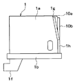
図1〜図3に示される距離検出装置は、車両に搭載されるもので、例えば、図2、図3における紙面右方向が車両前方を向くように配置され、例えばオートクルーズ時に車両前方の先行車等の障害物と自車両との距離を検出するレーザレーダとして用いられる。 The distance detection device shown in FIGS. 1 to 3 is mounted on a vehicle, and is arranged, for example, so that the right direction in FIG. 2 and FIG. 3 faces the front of the vehicle. It is used as a laser radar that detects the distance between an obstacle such as a car and the host vehicle.
距離検出装置は、略立方体形状で構成された樹脂製のケース1内に各種部品が収容されて構成されている。
The distance detection device is configured by housing various components in a
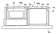
ケース1は、第1ケース部1aと第2ケース部1bとによって構成されている。第1ケース部1aは、一面が開口する箱型を成しており、この第1ケース部1aによって構成される収容スペース内に、各種部品が収容されるようになっている。第1ケース部1aは、基本的には同じ材料の樹脂によって構成されているが、第1ケース部1aのうち車両前方に向けられる面において、左右に並べられて、例えばガラスやアクリル樹脂等の透光性部材によって構成された投射窓部1cと入射窓部1dが備えられた構成となっている。
The
そして、図1に示されるように、投射窓部1cおよび入射窓部1dの前方には、それぞれ合わせガラス10a、10bが配置されている。合わせガラス10a、10bは、例えば、複数枚のガラス(例えばソーダ石灰ガラス)に樹脂フィルムを挟み込んで強力に密着させたもので、割れても破片が飛び散りにくく、また貫通しにくい性質を有しており、投射窓部1cおよび入射窓部1dよりも高い強度で構成されている。
And as FIG. 1 shows, the laminated
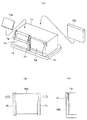
図4(a)は、距離検出装置のケース1に合わせガラス10a、10bを取り付ける時の様子を示した斜視図、図4(b)、(c)は、合わせガラス10bを入射窓部1cの前方に取り付けたときの様子を示す正面図および側面図である。
FIG. 4A is a perspective view showing a state when the laminated
各合わせガラス10a、10bは、投射窓部1cおよび入射窓部1dの外形よりも若干大きめに構成されている。第1ケース部1aにおける投射窓部1cおよび入射窓部1dの両側には、スライド溝1g、1hが構成されており、これらスライド溝1g、1h内に合わせガラス10a、10bのうち投射窓部1cおよび入射窓部1dからはみ出した部分、つまり合わせガラス10a、10bの外縁部が挿入されている。
Each laminated
具体的には、スライド溝1g、1hの上部は、弾性変形によって両側に広がるようになっており、この弾性変形によってスライド溝1g、1hの上部を広げた状態で、スライド溝1g、1h内に各合わせガラス10a、10bが挿入される。そして、各合わせガラス10a、10bを挿入した後、スライド溝1g、1hの上部を元の形状に戻すと、スライド溝1g、1hの上端がフックとして機能し、合わせガラス10a、10bがスライド溝1g、1h内に固定されるようになっている。
Specifically, the upper portions of the
なお、各合わせガラス10a、10bと投射窓部1cおよび入射窓部1dとは互いに接触した状態となっていてもよいが、これらの間に、例えば、所定量の隙間が形成されるようにし、これらが密着しないようにするのが好ましい。もちろん、これらの間に、透明な樹脂フィルムを配置することで、これらが互いに密着した状態となるようにしても良い。
In addition, although each laminated
第2ケース部1bは、例えば樹脂などによって構成され、第1ケース部1aの開口した面に、シール部材1eを介して組みつけられている。
The
なお、図3に示されるように、第2ケース部1bの一部には、ケース1から部分的に突出したコネクタ1fが配置されている。そして、このコネクタ1fを介して、ケース1内外の電気的接続が行えるようになっている。
As shown in FIG. 3, a
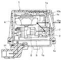
このように構成されるケース1内に、各種部品が収容されている。具体的には、ケース1内には、発光部2、反射ミラー3およびポリゴンミラー4が備えられていると共に、距離検出装置を制御するための制御部(図示せず)などが備えられた回路基板5が備えられている。また、ケース1内には、入射窓部1dと対向するように受光部6も配置されている。
Various parts are accommodated in the
発光部2は、回路基板5に備えられた制御部からの駆動信号に基づいて駆動されるもので、反射ミラー3に向けてレーザ光の照射を行うようになっている。例えば、この発光部2は、レーザダイオードによって構成され、パルス状の探査用電磁波となるレーザ光(探査光)を発生するようになっている。
The
反射ミラー3は、発光部2が発したレーザ光を反射し、ポリゴンミラー4に向けて照射するためのものである。この反射ミラー3は、ケース1の内壁に固定された支持部7により、ケース1に対して揺動可能に支持されている。そして、回路基板5に備えられた制御部によって駆動される図示しないモータにて反射ミラー3が揺動されることで、紙面垂直方向を軸とした反射角度の微調整(例えば、1度程度の調整)が行われるようになっている。
The reflection mirror 3 is for reflecting the laser beam emitted from the
ポリゴンミラー4は、六角錐の先端部分を切り取ったような六角錐台状を成している。このポリゴンミラー4は、ケース1の上面側において、六角錐軸を中心として回転可能なように支持されており、回路基板5に備えられた制御部によって駆動される図示しないモータによって回転駆動されるようになっている。このポリゴンミラー4は、その側面がすべて反射ミラーとして働くようになっており、スキャンミラーとして機能する。
The
具体的には、ポリゴンミラー4は、発光部2が発したレーザ光が反射ミラー3で反射されると、そのレーザ光をさらに反射させ、第1ケース部1aの投射窓部1cを通じてその反射光を車両前方に導くようになっている。そして、モータによってポリゴンミラー4が駆動されると、その回転に応じてポリゴンミラー4の側面の角度が変わることから、反射光の投射角が変わり、車両前方における所定の範囲がスキャンされるようになっている。
Specifically, when the laser light emitted from the
受光部6は、フレネルレンズと例えばフォトダイオードによって構成される受光素子などによって構成され、フレネルレンズによってレーザ光を集光し、受光素子に集光されたレーザ光が照射されるとその受光強度に対応する出力電流もしくは出力電圧を発生するようになっている。この受光部6により、ケース1の上方に照射されたレーザ光を検出できるようになっている。そして、この受光部6の出力電流もしくは出力電圧は、回路基板5に備えられた制御部に入力されるようになっている。
The
また、受光部6は、ポリゴンミラー4に対して横置き、すなわちポリゴンミラー4の回転軸の垂直方向にずらされて配置されている。
Further, the
次に、本実施形態のように構成された距離検出装置の作動について説明する。 Next, the operation of the distance detection device configured as in the present embodiment will be described.
上記構成の距離検出装置は、例えば車室内に備えられたオートクルーズコントロールのスイッチが投入されると、前方車両との距離の検出を行う。 The distance detecting device having the above-described configuration detects the distance to the vehicle ahead when, for example, an auto cruise control switch provided in the passenger compartment is turned on.
まず、制御部からの駆動信号に基づいてモータが駆動され、反射ミラー3が所定の角度に調整される。そして、発光部2から所定のタイミングでレーザ光が照射され、そのレーザ光が反射ミラー3およびポリゴンミラー4で反射され、投射窓部1cから車両前方に照射される。このレーザ光が自車両の前方に位置する先行車両などによって反射すると、その反射光が入射窓部1dを通じてフレネルレンズで集められ、受光素子に照射される。
First, the motor is driven based on the drive signal from the control unit, and the reflection mirror 3 is adjusted to a predetermined angle. Then, laser light is emitted from the
これにより、受光素子は受けたレーザ光の強度に応じた出力電流もしくは出力電圧を発生させる。これが制御部によって検知され、制御部は、そのレーザ光を照射したタイミングとレーザ光が検出されたタイミングの時間差、つまり入力時間差とレーザ光の速度とから次式より先行車両との距離を検出する。 Thereby, the light receiving element generates an output current or an output voltage corresponding to the intensity of the received laser beam. This is detected by the control unit, and the control unit detects the distance from the preceding vehicle from the following equation from the time difference between the timing of the laser light irradiation and the timing at which the laser light is detected, that is, the input time difference and the speed of the laser light. .
(数1)
レーザ光の速度×入力時間差/2
このようにして先行車両と自車両との距離が検出されると、その検出結果に応じた出力がコネクタ1fを介してケース1の外部、例えばエンジンECUやブレーキECUなどに出力される。これにより、先行車両と自車両との距離が所定距離に維持されるように、エンジン出力もしくは制動力が制御されるようになっている。
(Equation 1)
Laser beam speed x input time difference / 2
When the distance between the preceding vehicle and the host vehicle is detected in this manner, an output corresponding to the detection result is output to the outside of the
続いて、本実施形態に示す距離検出装置により得られる効果について説明する。 Then, the effect acquired by the distance detection apparatus shown in this embodiment is demonstrated.
上述したように、本実施形態に示す距離検出装置では、投射窓部1cおよび入射窓部1dの前方に合わせガラス10a、10bを配置した構成となっている。
As described above, the distance detection device shown in the present embodiment has a configuration in which the
このため、合わせガラス10a、10bによって投射窓部1cおよび入射窓部1dが覆われて保護される。したがって、飛び石などの物体が距離検出装置に当たったとしても、投射窓部1cおよび入射窓部1dが割れるのではなく、合わせガラス10a、10bが損傷を受けることになり、投射窓部1cおよび入射窓部1dが損傷を受けて距離検出装置が動作不良を起こすことを防止することができる。
For this reason, the
また、合わせガラス10a、10bは、破損したときにクモの巣状にヒビが入るため、合わせガラス10a、10bが破損したことを誇張することが可能となる。これにより、例えば、距離検出装置に投射窓部1cに付着した汚れの検出が行える機能がついているものであれば、合わせガラス10a、10bの破損部分によってレーザ光が乱反射することから、合わせガラス10a、10bの破損を汚れと同様に検出することが可能である。また、距離検出装置が、システム的に機能しなくなったときに、その旨を警告ランプや液晶表示器を通じて表示するシステム構成となっている場合には、その表示を通じてドライバに合わせガラス10a、10bの破損を知らせることも可能である。
Moreover, since the
そして、スライド溝1g、1hの上部を弾性変形させれば、容易に合わせガラス10a、10bを取り外し可能であるため、合わせガラス10a、10bを取り替えさえすればメンテナンスを行うことができる。したがって、メンテナンス性を良くすることが可能となるという効果も得られる。
If the upper portions of the
(他の実施形態)
上記実施形態では、合わせガラス10a、10bをスライド溝1g、1hによって固定する例について説明したが、その他の固定形態であっても構わない。例えば、第1ケース部1aの樹脂部のうち投射窓部1cおよび入射窓部1dの両側に位置する部分に接着剤を塗布し、この接着剤によって合わせガラス10a、10bを固定するようにしても良い。
(Other embodiments)
In the above embodiment, the example in which the
この場合、合わせガラス10a、10bを固定している接着剤として、溶剤によって容易に溶かすことが可能なものを用いれば、接着剤を溶かすことにより、容易に合わせガラス10a、10bのみを第1ケース1aから脱着することが可能である。
In this case, if an adhesive that can be easily dissolved by a solvent is used as the adhesive that fixes the
そして、接着剤を溶剤で溶かせば容易に合わせガラス10a、10bを取り外し可能であるため、合わせガラス10a、10bを取り替えさえすればメンテナンスを行うことができる。したがって、メンテナンス性を良くすることが可能となるという効果も得られる。
And since the
もちろん、合わせガラス10a、10bをネジによって固定する手法、ピンによって固定する手法、バネによって固定する手法、どのようなものであっても構わない。
Of course, any method may be used, such as a method of fixing the
また、上記実施形態では、強化板部材として合わせガラスを用いる例について説明したが、強化ガラス等、他の板部材を採用することも可能である。 Moreover, although the said embodiment demonstrated the example which uses a laminated glass as a tempered board member, it is also possible to employ | adopt other board members, such as tempered glass.
なお、上記実施形態では、距離検出に光波を使用するものを例に挙げて説明したが、ミリ波等の他の探査用電磁波を使うものについても本発明を適用することができる。すなわち、電磁波を電磁波発生部から出射し、それを障害物に反射させると共に、反射した電磁波を電磁波受取部によって受け取ることで、距離の検出を行うようなものであれば、どのようなものに関しても本発明を適用することができる。 In the above-described embodiment, an example using light waves for distance detection has been described as an example. However, the present invention can also be applied to those using other exploration electromagnetic waves such as millimeter waves. That is, as long as the electromagnetic wave is emitted from the electromagnetic wave generator, reflected by an obstacle, and received by the electromagnetic wave receiver, the distance can be detected. The present invention can be applied.
勿論、距離検出装置を構成する各部品の配置形態についても、上記実施形態に限るものではなく、どのような配置形態とされていたも、本発明を適用することができる。 Of course, the arrangement form of each component constituting the distance detection device is not limited to the above embodiment, and the present invention can be applied to any arrangement form.
1…ケース、1a…第1ケース部、1b…第2ケース部、1c…投射窓部、
1d…入射窓部、1g、1h…スライド溝、2…発光部、3…反射ミラー、
4…ポリゴンミラー、5…回路基板、6…受光部、7…支持部、
10a、10b…合わせガラス。
DESCRIPTION OF
1d: entrance window portion, 1g, 1h: slide groove, 2 ... light emitting portion, 3 ... reflection mirror,
4 ... Polygon mirror, 5 ... Circuit board, 6 ... Light receiving part, 7 ... Supporting part,
10a, 10b ... Laminated glass.
Claims (5)
前記ケース内に配置され、探査用電磁波を出射する電磁波発生部(2)と、
前記ケースに形成され、前記電磁波発生部からの前記探査用電磁波を通過させる透波性材料で構成された投射窓部(1c)と、
前記ケース内に配置され、前記探査用電磁光の反射波を受け取る電磁波受光部(6)と、
前記ケースに形成され、前記電磁波受取部が受け取る前記反射波を通過させる透波性材料で構成された入射窓部(1d)とを備え、
前記電磁波発生部が出射した前記探査用電磁波を前記投射窓部を通じて前記ケースの外部に向けて出射したのち、前記ケースの外部で反射してきた前記探査用電磁波を前記電磁波受取部で受け取り、それに基づいて前記探査用電磁波が反射させられた障害物までの距離を検出する距離検出装置であって、
前記投射窓部および前記入射窓部の前方に配置され、前記電磁波を透過する透波性材料で構成された強化板部材(10a、10b)を備え、
前記強化板部材によって前記投射窓部および前記入射窓部が覆われていることを特徴とする距離検出装置。 Case (1, 1a, 1b);
An electromagnetic wave generator (2) arranged in the case and emitting an electromagnetic wave for exploration;
A projection window portion (1c) formed of a wave-transmitting material that is formed in the case and allows the exploration electromagnetic wave from the electromagnetic wave generation portion to pass through;
An electromagnetic wave receiving part (6) disposed in the case and receiving a reflected wave of the exploration electromagnetic light;
An incident window portion (1d) formed of a wave transmissive material that is formed in the case and allows the reflected wave received by the electromagnetic wave receiving portion to pass through;
After the electromagnetic wave for exploration emitted by the electromagnetic wave generation part is emitted toward the outside of the case through the projection window part, the electromagnetic wave for exploration reflected from the outside of the case is received by the electromagnetic wave receiving part, and based thereon A distance detecting device for detecting a distance to the obstacle reflected by the search electromagnetic wave,
Reinforcing plate members (10a, 10b) that are arranged in front of the projection window and the incident window and are made of a wave-transmitting material that transmits the electromagnetic wave,
The distance detecting apparatus, wherein the reinforcing plate member covers the projection window and the incident window.
Priority Applications (3)
| Application Number | Priority Date | Filing Date | Title |
|---|---|---|---|
| JP2004104121A JP2005291789A (en) | 2004-03-31 | 2004-03-31 | Distance detecting apparatus |
| DE102005013817A DE102005013817A1 (en) | 2004-03-31 | 2005-03-24 | Object detection device with reinforcing element |
| US11/093,838 US20050219503A1 (en) | 2004-03-31 | 2005-03-30 | Object detecting apparatus having reinforcing member |
Applications Claiming Priority (1)
| Application Number | Priority Date | Filing Date | Title |
|---|---|---|---|
| JP2004104121A JP2005291789A (en) | 2004-03-31 | 2004-03-31 | Distance detecting apparatus |
Publications (1)
| Publication Number | Publication Date |
|---|---|
| JP2005291789A true JP2005291789A (en) | 2005-10-20 |
Family
ID=35034273
Family Applications (1)
| Application Number | Title | Priority Date | Filing Date |
|---|---|---|---|
| JP2004104121A Pending JP2005291789A (en) | 2004-03-31 | 2004-03-31 | Distance detecting apparatus |
Country Status (3)
| Country | Link |
|---|---|
| US (1) | US20050219503A1 (en) |
| JP (1) | JP2005291789A (en) |
| DE (1) | DE102005013817A1 (en) |
Cited By (2)
| Publication number | Priority date | Publication date | Assignee | Title |
|---|---|---|---|---|
| CN113454483A (en) * | 2018-12-21 | 2021-09-28 | 旭硝子欧洲玻璃公司 | Laser radar detection device with releasable protective layer |
| JP7486520B2 (en) | 2019-04-26 | 2024-05-17 | エージーシー グラス ユーロップ | Protective housing for sensing devices |
Families Citing this family (3)
| Publication number | Priority date | Publication date | Assignee | Title |
|---|---|---|---|---|
| US7697120B2 (en) * | 2006-11-27 | 2010-04-13 | Riegl Laser Measurement Systems Gmbh | Scanning apparatus |
| US8087875B2 (en) * | 2007-09-28 | 2012-01-03 | Krouse Wayne F | Machine for increased hydro power generation |
| US20090281703A1 (en) * | 2008-05-12 | 2009-11-12 | Hudson Meilleur | Cruise control cancel device for passengers in vehicles |
Family Cites Families (5)
| Publication number | Priority date | Publication date | Assignee | Title |
|---|---|---|---|---|
| US6940418B2 (en) * | 1999-05-04 | 2005-09-06 | Intellimats, Llc | Electronic floor display cleaning system and protective cover |
| JP2001272226A (en) * | 2000-03-24 | 2001-10-05 | Koito Mfg Co Ltd | Location-measuring laser device |
| JP3468212B2 (en) * | 2000-07-14 | 2003-11-17 | 株式会社デンソー | Housing for reflection measurement device |
| SE522695C2 (en) * | 2000-11-17 | 2004-03-02 | Foss Tecator Ab | Method and apparatus for image acquisition of small particles for analysis of the quality of the particles |
| JP3814270B2 (en) * | 2003-10-09 | 2006-08-23 | 本田技研工業株式会社 | Automatic switchgear for vehicles |
-
2004
- 2004-03-31 JP JP2004104121A patent/JP2005291789A/en active Pending
-
2005
- 2005-03-24 DE DE102005013817A patent/DE102005013817A1/en not_active Withdrawn
- 2005-03-30 US US11/093,838 patent/US20050219503A1/en not_active Abandoned
Cited By (2)
| Publication number | Priority date | Publication date | Assignee | Title |
|---|---|---|---|---|
| CN113454483A (en) * | 2018-12-21 | 2021-09-28 | 旭硝子欧洲玻璃公司 | Laser radar detection device with releasable protective layer |
| JP7486520B2 (en) | 2019-04-26 | 2024-05-17 | エージーシー グラス ユーロップ | Protective housing for sensing devices |
Also Published As
| Publication number | Publication date |
|---|---|
| US20050219503A1 (en) | 2005-10-06 |
| DE102005013817A1 (en) | 2005-10-20 |
Similar Documents
| Publication | Publication Date | Title |
|---|---|---|
| US7382442B2 (en) | Object detector of vehicle | |
| KR101665938B1 (en) | Optical system of multi lidar scanner using mirror rotation | |
| JP4602303B2 (en) | An optical sensor device mounted on a vehicle for driving assistance and / or for automatically operating a system provided in the vehicle | |
| US20120187283A1 (en) | Laser radar system and light receiving device | |
| KR20070100159A (en) | Optical sensor device | |
| EP3133336A1 (en) | Vehicular lighting equipment | |
| US20050184224A1 (en) | Object detecting apparatus | |
| US7059522B2 (en) | Object detecting apparatus having hydrophilic light radiating window | |
| JP2019144072A (en) | Object detection device | |
| JP2016162682A (en) | Light emitting device | |
| WO2020195678A1 (en) | Distance measurement device | |
| US20050219503A1 (en) | Object detecting apparatus having reinforcing member | |
| JP4158725B2 (en) | Distance detector | |
| US7209272B2 (en) | Object detecting apparatus having operation monitoring function | |
| JP2007033153A (en) | Raindrop and dew condensation detector | |
| JP2005257324A (en) | Distance detector | |
| JP4305231B2 (en) | Distance detector | |
| JP4193724B2 (en) | Distance detector | |
| JP2002040136A (en) | Reflection-measuring instrument | |
| US20050184259A1 (en) | Object detection apparatus for a vehicle | |
| JP2010064642A (en) | Lighting system for moving body | |
| JP4341435B2 (en) | Distance detector | |
| JP2005233775A (en) | Distance detector | |
| CN111830705B (en) | Optical device, mounting system, and mobile device | |
| JP7275917B2 (en) | rangefinder |
Legal Events
| Date | Code | Title | Description |
|---|---|---|---|
| A621 | Written request for application examination |
Free format text: JAPANESE INTERMEDIATE CODE: A621 Effective date: 20060619 |
|
| A871 | Explanation of circumstances concerning accelerated examination |
Free format text: JAPANESE INTERMEDIATE CODE: A871 Effective date: 20061010 |
|
| A975 | Report on accelerated examination |
Free format text: JAPANESE INTERMEDIATE CODE: A971005 Effective date: 20061027 |
|
| A131 | Notification of reasons for refusal |
Free format text: JAPANESE INTERMEDIATE CODE: A131 Effective date: 20061114 |
|
| A02 | Decision of refusal |
Free format text: JAPANESE INTERMEDIATE CODE: A02 Effective date: 20070313 |