JP2005291330A - Oil passage structure of parallel hybrid vehicle - Google Patents
Oil passage structure of parallel hybrid vehicle Download PDFInfo
- Publication number
- JP2005291330A JP2005291330A JP2004106100A JP2004106100A JP2005291330A JP 2005291330 A JP2005291330 A JP 2005291330A JP 2004106100 A JP2004106100 A JP 2004106100A JP 2004106100 A JP2004106100 A JP 2004106100A JP 2005291330 A JP2005291330 A JP 2005291330A
- Authority
- JP
- Japan
- Prior art keywords
- oil
- oil passage
- transmission
- engine
- oil pump
- Prior art date
- Legal status (The legal status is an assumption and is not a legal conclusion. Google has not performed a legal analysis and makes no representation as to the accuracy of the status listed.)
- Pending
Links
Images
Classifications
-
- F—MECHANICAL ENGINEERING; LIGHTING; HEATING; WEAPONS; BLASTING
- F16—ENGINEERING ELEMENTS AND UNITS; GENERAL MEASURES FOR PRODUCING AND MAINTAINING EFFECTIVE FUNCTIONING OF MACHINES OR INSTALLATIONS; THERMAL INSULATION IN GENERAL
- F16H—GEARING
- F16H57/00—General details of gearing
- F16H57/04—Features relating to lubrication or cooling or heating
- F16H57/0434—Features relating to lubrication or cooling or heating relating to lubrication supply, e.g. pumps ; Pressure control
Landscapes
- Engineering & Computer Science (AREA)
- General Engineering & Computer Science (AREA)
- Mechanical Engineering (AREA)
- General Details Of Gearings (AREA)
- Arrangement Of Transmissions (AREA)
- Hybrid Electric Vehicles (AREA)
Abstract
Description
本発明は、エンジンと、モータジェネレータとを有し、これらの出力トルクを、トルク合成機構である差動装置を介してトランスミッションに伝達することにより、エンジン及びモータジェネレータの何れか一方又は双方で走行駆動力を得るようにしたハイブリッド車両に関するものである。 The present invention includes an engine and a motor generator, and these output torques are transmitted to a transmission via a differential device that is a torque synthesizing mechanism, so that either one or both of the engine and the motor generator travel. The present invention relates to a hybrid vehicle in which driving force is obtained.
従来のハイブリッド車両としては、例えばエンジンの出力トルクと、モータジェネレータの出力トルクとを、遊星歯車機構からなる差動装置によって合成し、つまりトルク合成機構によって合成し、それをトランスミッションを介して駆動輪に伝達するものがある。このようなハイブリッド車両は、エンジン始動時にモータジェネレータを逆回転して駆動したり、発進時にエンジンやモータジェネレータが回転した後に差動装置の出力軸が回転し始めることを考慮すると、トランスミッションに作動油を供給するためのオイルポンプをエンジンによって駆動する必要がある。そこで、オイルポンプをエンジンによって駆動するものとしては、例えば、オイルポンプをモータジェネレータとトランスミッションとの間に備えたもの、即ちエンジン、モータジェネレータ、オイルポンプ、トランスミッションの順序に配置したもの(例えば特許文献1)や、オイルポンプをエンジンとモータジェネレータとの間に備えたもの、即ちエンジン、オイルポンプ、モータジェネレータ、トランスミッションの順序に配置したもの(例えば特許文献2)などがある。なお、トランスミッション用の作動油は、トランスミッションケースの下部の油溜りに貯留される。
しかしながら、前記特許文献1に記載のハイブリッド車両では、エンジンとオイルポンプとの間にモータジェネレータが介在しているので、エンジンの出力軸に直接オイルポンプを設けて駆動することができず、例えばオイルポンプ駆動用の遊星歯車機構を設けなければならず、構造が複雑で、コスト的にも不利である。このような問題は、トランスミッション用オイルポンプをエンジンで直接駆動できないハイブリッド車両に共通するものであり、オイルポンプ駆動用の遊星歯車機構を介装する代わりに、電動オイルポンプを用いるなど、構造的にも、コスト的にも不利である。
However, in the hybrid vehicle described in
一方、前記特許文献2に記載のハイブリッド車両では、エンジンでオイルポンプを直接駆動する(ベルトや歯車機構は介在したとしても)ことができるので、前述のような問題は軽減される。しかしながら、通常はトランスミッション用の作動油はトランスミッションの変速機構の潤滑油としても兼用されることから油溜りはトランスミッションケースの下部に設けられているので、オイルポンプとトランスミッションケースとの油路(吸入、吐出とも)が長くなる。一般に、この種の油路では、オイルポンプが停止していると、内部の作動油が油溜りに回収される構造となっているので、エンジン停止(アイドルストップを含む)後の再始動時や、長期放置後、極低温時等には、油路内の作動油が抜けてしまい、油圧の立上りが遅くなるという問題が生じる。
On the other hand, in the hybrid vehicle described in
本発明は上記諸問題を解決するために開発されたものであり、トランスミッションの油溜りとオイルポンプとの間の油路内の作動油が抜けにくく、もって油圧の立上りが早く、同時に、構造的、コスト的に有利なハイブリッド車両における油路構造を提供することを目的とするものである。 The present invention has been developed to solve the above-mentioned problems, and it is difficult for hydraulic oil in the oil passage between the oil sump of the transmission and the oil pump to escape, so that the hydraulic pressure rises quickly and at the same time structurally. An object of the present invention is to provide an oil passage structure in a hybrid vehicle that is advantageous in terms of cost.
上記諸問題を解決するため、本発明のパラレルハイブリッド車両における油路構造は、エンジン、該エンジンに駆動されるオイルポンプ、モータジェネレータ、変速機構を有するトランスミッションが、この順序で配設され、前記エンジンのトルクとモータジェネレータのトルクとを合成するトルク合成機構を備え、前記トランスミッションには油溜りが設けられ、前記オイルポンプが前記油溜りの作動油を吸入及び加圧吐出して、前記トランスミッションの変速機構に作動油を供給するハイブリッド車両において、前記トランスミッションの変速機構を収納するトランスミッションケースのエンジン側に、前記トルク合成機構を収納する合成機構ハウジングを配設し、前記合成機構ハウジングに、前記油溜りの作動油をオイルポンプに吸入する吸入油路及びオイルポンプから作動油を吐出する吐出油路の少なくとも何れか一方を形成し、前記合成機構ハウジングに形成された油路の一部又は全部に、前記油溜りとは個別の油溜り部を形成したことを特徴とするものである。 In order to solve the above problems, an oil passage structure in a parallel hybrid vehicle according to the present invention includes an engine, an oil pump driven by the engine, a motor generator, and a transmission having a speed change mechanism arranged in this order. A torque synthesizing mechanism that synthesizes the torque of the motor generator and the torque of the motor generator. The transmission is provided with an oil sump, and the oil pump sucks and pressurizes and discharges the hydraulic oil in the oil sump. In a hybrid vehicle that supplies hydraulic oil to a mechanism, a synthesizing mechanism housing that houses the torque synthesizing mechanism is disposed on the engine side of a transmission case that houses the transmission mechanism of the transmission, and the oil reservoir is disposed in the synthesizing mechanism housing. Intake of hydraulic oil into oil pump At least one of a suction oil passage and a discharge oil passage that discharges hydraulic oil from an oil pump, and a part or all of the oil passage formed in the synthetic mechanism housing is separated from the oil reservoir. It is characterized in that a reservoir is formed.
而して、本発明のパラレルハイブリッド車両における油路構造によれば、エンジン、該エンジンに駆動されるオイルポンプ、モータジェネレータ、変速機構を有するトランスミッションの順序で配設すると共に、変速機構を収納するトランスミッションケースのエンジン側に、トルク合成機構を収納する合成機構ハウジングを配設し、その合成機構ハウジングに、トランスミッションの油溜りの作動油をオイルポンプに吸入する吸入油路及びオイルポンプから作動油を吐出する吐出油路の少なくとも何れか一方を形成し、合成機構ハウジングに形成された油路の一部又は全部に、トランスミッションに設けられた油溜りとは個別の油溜り部を形成したことにより、トランスミッションの油溜りとオイルポンプとの間の油路内の作動油が抜けにくく、もってエンジン始動時の油圧の立上りが早くなると共に、また、オイルポンプをエンジンで直接駆動することにより、構造的、コスト的に有利である。 Thus, according to the oil passage structure in the parallel hybrid vehicle of the present invention, the engine, the oil pump driven by the engine, the motor generator, and the transmission having the transmission mechanism are arranged in this order, and the transmission mechanism is accommodated. A composite mechanism housing that houses the torque synthesis mechanism is disposed on the engine side of the transmission case, and the hydraulic oil from the intake oil passage and the oil pump that draws the hydraulic oil in the oil reservoir of the transmission into the composite mechanism housing is supplied to the composite mechanism housing. By forming at least one of the discharge oil passages to be discharged and forming an oil sump portion that is separate from the oil sump provided in the transmission in part or all of the oil passage formed in the composite mechanism housing, The hydraulic fluid in the oil passage between the oil sump of the transmission and the oil pump Ku, the faster oil pressure rise at the start of the engine has also by driving directly the oil pump by the engine, structural, it is cost-effective.
以下、本発明のハイブリッド車両の油路構造の実施の形態を図面に基づいて説明する。
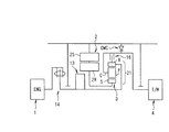
図1は、本発明のハイブリッド車両の第1実施形態を示す回転駆動源及び駆動系の概略構成図であり、車両側面視における上半部を示している。本実施形態のハイブリッド車両では、エンジン1及び発電機及び電動機として作用する3相同期モータ/発電機で構成される交流式のモータジェネレータ2の出力側が、夫々、トルク合成機構である差動装置(遊星歯車機構)3の入力側に連結され、この差動装置3の出力側がトルクコンバータ等の発進装置を搭載していないトランスミッション4の入力側に接続され、トランスミッション4の出力側が図示しない終減速装置等を介して駆動輪に連結されている。また、この実施形態では、前記モータジェネレータ2とエンジン1との間にオイルポンプ13が配設されており、このオイルポンプ13で創成される流体圧がトランスミッション4の制御に用いられる。このオイルポンプ13はエンジン1によって直接的に駆動される。
Embodiments of an oil passage structure for a hybrid vehicle according to the present invention will be described below with reference to the drawings.
FIG. 1 is a schematic configuration diagram of a rotary drive source and a drive system showing a first embodiment of a hybrid vehicle of the present invention, and shows an upper half portion in a vehicle side view. In the hybrid vehicle of this embodiment, the output side of the
前記エンジン1はエンジン用コントローラによって制御される。また、前記モータジェネレータ2は、ステータ2Sとロータ2Rとを有し、充電可能なバッテリやコンデンサで構成される蓄電装置に接続されたモータジェネレータ駆動回路(インバータ)によって駆動され、モータジェネレータ駆動回路はモータジェネレータ用コントローラによって制御される。
The
また、差動装置3は、トルク合成機構として遊星歯車機構21を備えて構成されている。この遊星歯車機構21は、エンジン1とモータジェネレータとの間で差動機能を発現しながらトルク合成機構をなすものである。そして、サンギヤSと、その外周側に等角間隔で噛合する複数のピニオンPと、各ピニオンPを連結するピニオンキャリヤCと、ピニオンPの外側に噛合するリングギヤRとを備え、この遊星歯車機構21のリングギヤRがエンジン1に連結され、同じく遊星歯車機構21のサンギヤSがモータジェネレータ2のロータ2Rに連結され、同じく遊星歯車機構21のピニオンキャリヤCがトランスミッション4の入力側に連結されている。
The differential device 3 includes a
また、前記遊星歯車機構21のピニオンキャリヤC、即ちトランスミッション4の入力側とエンジン1の出力側との間には、両者の連結状態を制御するためのロックアップクラッチ16が介装されている。また、前記遊星歯車機構21のピニオンキャリヤC、即ちトランスミッション4の入力側とケース14との間には、当該ピニオンキャリヤC、及びトランスミッション4の回転方向を正回転にのみ規制し、逆回転では締結して、当該逆回転を許容しないワンウエイクラッチOWCが介装されている。なお、前記エンジン1と遊星歯車機構21のリングギヤRとの間にはダンパ14が介装されている。
A lock-
さらに、前記トランスミッション4は、トランスミッション用コントローラによって、走行速度とスロットル開度とをもとに予め設定された変速制御マップを参照して決定された例えば第1速〜第4速の変速比に制御される。ちなみに、このトランスミッション4は周知のオートマチックトランスミッションであり、例えば二組の遊星歯車機構の各要素を複数の摩擦要素によって締結解放することで前進4速の変速比を達成可能とする変速機構4aを備えており、各摩擦要素の締結解放に前記オイルポンプ13で創成された油圧が、コントロールバルブ23内の各種調圧弁や電磁弁などにより調圧されて用いられる。また、このトランスミッション4の変速機構4aには、締結することにより図示しない駆動輪側からの逆駆動力、所謂路面反力トルクをトルク合成機構側に伝達可能なエンジンブレーキ用クラッチを有している。なお、このトランスミッション用コントローラは、前記エンジン用コントローラやモータジェネレータ用コントローラと相互通信を行っており、必要な情報は随時、互いに授受している。
Further, the transmission 4 is controlled by the transmission controller to a gear ratio of, for example, the first speed to the fourth speed determined by referring to a speed change control map set in advance based on the travel speed and the throttle opening. Is done. Incidentally, this transmission 4 is a well-known automatic transmission, and includes, for example, a
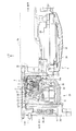
図2には、オイルポンプ13、モータジェネレータ2、差動装置3の具体的な構成の詳細を示す。図2は、それらの縦断面図の車両下半部だけを示す。図中の符号22は、トランスミッション4を収納するトランスミッションケース、符号18は、トランスミッション4のインプットシャフト、符号19は、トランスミッションケース4の車両前方端部に立設されて前記入力軸18を回転自在に支持するための中間壁である。また、トランスミッションケース22の車両下部には、前記トランスミッション4の摩擦要素の締結解放状態を駆動するコントロールバルブボディ23が設けられ、更にその下部にオイルパン24が設けられ、このオイルパン24内に作動油(具体的にはオートマチックトランスミッションフルード)を貯留して油溜り100を形成している。更に、この油溜り100の作動油は、オイルポンプ13で吸入され、加圧吐出される。なお、図中の符号25は、オイルパン24内の作動油を吸入濾過するストレーナである。
FIG. 2 shows details of specific configurations of the
前記トランスミッションケース22の中間壁19の車両前方、つまりエンジン1側には、前記トルク合成機構である差動装置3を収納するための合成機構ハウジング本体26aが取付けられており、この合成機構ハウジング本体26aの内部に、差動装置3、モータジェネレータ2、オイルポンプ13が収納されている。具体的には、前記トランスミッション4のインプットシャフト18の車両前方にインターミディエイトシャフト27が回転自在に配設され、このインターミディエイトシャフト27とインプットシャフト18との間に差動装置3が介装され、その車両前方で且つ差動装置3の外側、つまり外周側にモータジェネレータ2が配設され、モータジェネレータ2の車両前方で且つモータジェネレータ2の内側、つまり内周側にオイルポンプ13が配設されている。なお、合成機構ハウジング本体26aの車両前方、つまりエンジン1側にはオイルポンプカバー18が取付けられ、その内部にダンパ14が収納されており、合成機構ハウジング本体26aとオイルポンプカバー28とで合成機構ハウジング26を構成している。
A synthesizing
本実施形態では、モータジェネレータ2の車両後方内周側に差動装置3を、車両前方内周側にオイルポンプ13をレイアウトすることにより、オイルポンプ13から差動装置3までの距離を短縮することができる。モータジェネレータ2で、より大きな駆動トルク或いは制動トルク(=発電量)を得るためには、ステータ2Sやロータ2Rの半径を大きくするのが望ましい。そこで、モータジェネレータ2のステータ2Sやロータ2Rを大径化し、その内周側に、差動装置3やオイルポンプ13を配設する。特に、ロータ2Rをインターミディエイトシャフト27に連結するためのホイール状のロータサポート2RSの車両前方にオイルポンプハウジング28を設け、その内部にオイルポンプ13を配設することによりオイルポンプ13−モータジェネレータ2間の距離の短縮化を図っている。
In the present embodiment, the distance from the
更に、環境面では、差動装置3やオイルポンプ13の周りが作動油で湿潤状態、所謂ウエットな状態であるのに対して、モータジェネレータ2の内部は乾燥状態、つまりドライでなければならない。そこで、モータジェネレータ2のロータサポート2RSの車両後方側において、当該ロータサポート2RSと合成機構ハウジング本体26aとの間に後方区画壁29を設け、この後方区画壁29とロータサポート2RSとの間にシール付きベアリング30を設けて当該ロータサポート2RSを回転自在に支持すると共に、ロータサポート2RSの車両前方側において、当該ロータサポート2RSと合成機構ハウジング本体26aとの間に前方区画壁31を設け、この前方区画壁31とロータサポート2RSとの間にシール付きベアリング32を設けて当該ロータサポート2RSを回転自在に支持することにより、モータジェネレータ2の内部をドライな状態に維持できるようにした。
Furthermore, in terms of the environment, the periphery of the differential device 3 and the
また、ここでも、後方区画壁29側、つまり差動装置3側のシール付きベアリング30よりも前方区画壁31側、つまりオイルポンプ13側のシール付きベアリング32を大径化することにより、より大径の、つまり効率のよいオイルポンプ13をモータジェネレータ2の内部に収納できるようにして、オイルポンプ13とモータジェネレータ2との距離の短縮化を図った。また、このようにオイルポンプ13と差動装置3との距離を短縮し、結果的にオイルポンプ13とトランスミッションケース22との距離を短縮化することにより、後述するように、当該トランスミッションケース22のオイルパン24から作動油をオイルポンプ13に吸入したり、或いはオイルポンプ13から吐出された加圧作動油をトランスミッション4に吐出したりするための油路が短くなるという効果もある。
Also here, the diameter of the bearing 32 with the seal on the
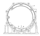
図3には、トランスミッションケース22に形成された吸入油路33及び吐出油路34の断面形状(実質的にはトランスミッションケース22に開口している端面の形状)を示す。このトランスミッションケース22に形成されている吸入油路33の一端は、図2に示すように、前記ストレーナ25に連結されており、これに連通して合成機構ハウジング本体26aに形成されている部分は、モータジェネレータ2の下方を経由してから上方に立ち上げられ、その他端がオイルポンプ13の吸入口13aに連結されている。一方の吐出油路34の一端はオイルポンプ13の吐出口に連結され、その他端がコントロールバルブボディ23に連結されている。なお、吸入油路33も吐出油路34も、合成機構ハウジング本体26aに形成されている油路の断面形状は図2に示すように互いに同形状である。つまり、これらの油路は、何れもモータジェネレータ2の外周を通って形成されている。
FIG. 3 shows the cross-sectional shapes of the
ここで、吸入油路33を例にとって説明すると、吸入油路33のうち、トランスミッションケース22に形成されている部分の合成機構ハウジング本体26a側端部は、コントロールバルブボディ23より車両上方に開口されている。一方、これに連通する合成機構ハウジング本体26a側の吸入油路33は、トランスミッションケース22の開口部22aから中間壁19を介して合成機構ハウジング本体26a側で一端下方に立下げられ、モータジェネレータ2の下方をとって車両前方に延長され、そこから車両上方に立上げられてオイルポンプ13に連結される。つまり、この吸入油路33は、合成機構ハウジング本体26a側とトランスミッションケース22との接続部位Sよりも低い位置を経由するように形成されている。
Here, the
オイルポンプ13が作動しているときには、この吸入油路33は作動油で満ちているが、オイルポンプ13が停止すると、吸入油路33のうち、トランスミッションケース22との接続部位Sよりも低い位置には作動油が残存して、ここが油溜り部35となる。従って、エンジンが停止しても、トランスミッションの油溜り100とオイルポンプ13との間の油路内の作動油が抜けにくくなり、もってエンジン始動時の油圧の立上りが早くなるとともに、また、オイルポンプをエンジンで直接駆動することにより、構造的、コスト的に有利である(請求項1に対応する効果)。このとき、本実施例では、例えば、オイルポンプ13が停止しているときの通常のオイルパン24内の作動油の液面高さをオイルレベルOLで表すと、接続部位Sがこれよりも高い位置に形成されているため、例え吸入油路33から余分な作動油がドレンされたとしても、油溜り35に残存している作動油の液面は、オイルパン24内のオイルレベルOLよりも高い。従って、オイルポンプ13と油溜り部35の作動油の液面との間のエアの量が少なく、つまり油溜り部中の作動油にエアが混入しにくく、もってオイルポンプ13が停止した後の油圧の立上りを早くすることができる(請求項3に対応する効果)。
When the
更に、合成機構ハウジング本体26aに形成された吸入油路33の前記トランスミッションケース22との接続部位Sよりも低い位置を経由するように吸入油路33を形成し、トランスミッションケース22との接続部位Sよりも低い部位を油溜り部35としたことにより、油溜り部35の形成が容易という効果がある(請求項2に対応する効果)。
また、吸入油路33や吐出油路34をモータジェネレータ2の外周に形成したことにより、エンジンが作動しているときには、モータジェネレータ2の外周を比較的温度の低い作動油が常時通過することになり、モータジェネレータ2の冷却効果を得ることができる。また、エンジンの停止時には、油溜り部35に残存した作動油によってモータジェネレータ2の冷却効果を得ることができる(請求項6に対応する効果)。
更に、本実施形態では、モータジェネレータ2の内部にオイルポンプ2や差動装置3を配設する構成としたため、やはりトランスミッションケース22からオイルポンプ13までの油路の長さを短くでき、その結果、油圧の立上りをより一層早めることができる。
Further, the
Further, since the
Furthermore, in the present embodiment, since the
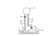
次に、本発明のハイブリッド車両の油路構造の第2実施形態について、図4を用いて説明する。図4は、前記第1実施形態のオイルポンプ13やオイルパン24、ストレーナ25、コントロールバルブボディ23を用い、オイルポンプ13とストレーナ25とを連通する吸入油路33、オイルポンプ13とコントロールバルブボディ23とを連通する吐出油路34を概念的に描いたものである。この実施形態では、吸入油路33の途中に、オイルポンプ13への吸入方向への作動油の流れは許容し且つ反対方向への流れを禁止する第1ワンウエイバルブ36を設け、このワンウエイバルブ36からストレーナ25までの吸入油路33を油溜り部35とした。また、吐出油路34の途中に、コントロールバルブボディ23、つまりエンジン運転時のトランスミッション側への作動油の流れは許容し且つエンジン停止時のトランスミッション側への作動油の流れを禁止する第2ワンウエイバルブ37を設け、この第2ワンウエイバルブ37とオイルポンプ13までの吐出油路34を油溜り部35とした。つまり、オイルポンプ13が作動しているときには、吸入油路33も吐出油路34も作動油で満たされている。この状態から、オイルポンプ13を停止すると共に、夫々のワンウエイバルブ36、37が閉じられると各油路内が液密な状態となって作動油がドレンされなくなるので、ワンウエイバルブ36より下流側は作動油の油溜り部35となる。なお、この種のワンウエイバルブには、例えば特開2003−97748公報に記載されるものなどが挙げられる。
Next, 2nd Embodiment of the oil-path structure of the hybrid vehicle of this invention is described using FIG. FIG. 4 shows the
このように、オイルポンプの吸入方向或いは吐出方向への作動油の流れを許容し、逆方向への作動油の流れを禁止するワンウエイバルブを吸入或いは吐出油路内に設けることによっても、容易に油溜り部を形成することができ、これにより油溜り部中の作動油にエアが混入しにくくしてオイルポンプ作動時の油圧の立上りを早めることができる。また、本実施形態では、油路の形状に格別の限定がないので、油路長さを最短に設定することが可能となる(請求項4及び5に対応する効果)。 Thus, it is also easy to provide a one-way valve in the suction or discharge oil passage that allows the flow of hydraulic oil in the suction direction or discharge direction of the oil pump and prohibits the flow of hydraulic oil in the reverse direction. An oil reservoir can be formed, which makes it difficult for air to be mixed into the hydraulic oil in the oil reservoir and accelerates the rise of hydraulic pressure when the oil pump is operated. Moreover, in this embodiment, since there is no special limitation in the shape of an oil path, it becomes possible to set the oil path length to the shortest (effect corresponding to Claims 4 and 5).
1はエンジン
2はモータジェネレータ
3は差動装置
4はトランスミッション
13はオイルポンプ
14はダンパ
21は遊星歯車機構
22はトランスミッションケース
23はコントロールバルブボディ
24はオイルパン
25はストレーナ
26は合成機構ハウジング
28はオイルポンプカバー
33は吸入油路
34は吐出油路
35は油溜り部
36,37はワンウエイバルブ
OWCはワンウエイクラッチ
Sはサンギヤ
Pはピニオン
Rはリングギヤ
Cはピニオンキャリヤ
1 is an
Claims (6)
Priority Applications (1)
| Application Number | Priority Date | Filing Date | Title |
|---|---|---|---|
| JP2004106100A JP2005291330A (en) | 2004-03-31 | 2004-03-31 | Oil passage structure of parallel hybrid vehicle |
Applications Claiming Priority (1)
| Application Number | Priority Date | Filing Date | Title |
|---|---|---|---|
| JP2004106100A JP2005291330A (en) | 2004-03-31 | 2004-03-31 | Oil passage structure of parallel hybrid vehicle |
Publications (1)
| Publication Number | Publication Date |
|---|---|
| JP2005291330A true JP2005291330A (en) | 2005-10-20 |
Family
ID=35324493
Family Applications (1)
| Application Number | Title | Priority Date | Filing Date |
|---|---|---|---|
| JP2004106100A Pending JP2005291330A (en) | 2004-03-31 | 2004-03-31 | Oil passage structure of parallel hybrid vehicle |
Country Status (1)
| Country | Link |
|---|---|
| JP (1) | JP2005291330A (en) |
Cited By (7)
| Publication number | Priority date | Publication date | Assignee | Title |
|---|---|---|---|---|
| WO2008065803A1 (en) * | 2006-11-27 | 2008-06-05 | Aisin Aw Co., Ltd. | Hybrid drive device |
| CN100436184C (en) * | 2005-11-25 | 2008-11-26 | 武汉理工大学 | Parallel hybrid power electric automobile power transmission system |
| JP2009001128A (en) * | 2007-06-20 | 2009-01-08 | Toyota Motor Corp | Hybrid driving device |
| WO2013065677A1 (en) * | 2011-11-04 | 2013-05-10 | アイシン・エィ・ダブリュ株式会社 | Vehicle drive device |
| CN103711884A (en) * | 2012-10-05 | 2014-04-09 | 本田技研工业株式会社 | Vehicle drive apparatus |
| CN110192049A (en) * | 2017-01-23 | 2019-08-30 | 伊顿智能动力有限公司 | The pump/motor with integrated speed changer used in hydraulic system |
| WO2024085138A1 (en) * | 2022-10-21 | 2024-04-25 | 株式会社クボタ | Work vehicle |
-
2004
- 2004-03-31 JP JP2004106100A patent/JP2005291330A/en active Pending
Cited By (15)
| Publication number | Priority date | Publication date | Assignee | Title |
|---|---|---|---|---|
| CN100436184C (en) * | 2005-11-25 | 2008-11-26 | 武汉理工大学 | Parallel hybrid power electric automobile power transmission system |
| WO2008065803A1 (en) * | 2006-11-27 | 2008-06-05 | Aisin Aw Co., Ltd. | Hybrid drive device |
| JP2008132812A (en) * | 2006-11-27 | 2008-06-12 | Aisin Aw Co Ltd | Hybrid driving device |
| US7891449B2 (en) | 2006-11-27 | 2011-02-22 | Aisin Aw Co., Ltd. | Hybrid drive apparatus |
| JP2009001128A (en) * | 2007-06-20 | 2009-01-08 | Toyota Motor Corp | Hybrid driving device |
| JP2013095389A (en) * | 2011-11-04 | 2013-05-20 | Aisin Aw Co Ltd | Drive device for vehicle |
| WO2013065677A1 (en) * | 2011-11-04 | 2013-05-10 | アイシン・エィ・ダブリュ株式会社 | Vehicle drive device |
| CN103764423A (en) * | 2011-11-04 | 2014-04-30 | 爱信艾达株式会社 | Vehicle drive device |
| US9447864B2 (en) | 2011-11-04 | 2016-09-20 | Aisin Aw Co., Ltd. | Vehicle drive device |
| CN103711884A (en) * | 2012-10-05 | 2014-04-09 | 本田技研工业株式会社 | Vehicle drive apparatus |
| CN110192049A (en) * | 2017-01-23 | 2019-08-30 | 伊顿智能动力有限公司 | The pump/motor with integrated speed changer used in hydraulic system |
| EP3571427A4 (en) * | 2017-01-23 | 2020-10-21 | Eaton Intelligent Power Limited | Pump/motor with integrated variator for use in hydraulic systems |
| US11255359B2 (en) | 2017-01-23 | 2022-02-22 | Danfoss Power Solutions Ii Technology A/S | Pump/motor with integrated variator for use in hydraulic systems |
| CN110192049B (en) * | 2017-01-23 | 2023-05-05 | 丹佛斯动力系统Ii技术有限公司 | Pump/motor with integrated transmission for use in a hydraulic system |
| WO2024085138A1 (en) * | 2022-10-21 | 2024-04-25 | 株式会社クボタ | Work vehicle |
Similar Documents
| Publication | Publication Date | Title |
|---|---|---|
| US11192444B2 (en) | Drive unit for a hybrid vehicle | |
| US7244208B2 (en) | Drive train for a hybrid vehicle | |
| JP4683140B2 (en) | Heating part cooling structure of vehicle drive device | |
| JP4815187B2 (en) | Vehicle power transmission device | |
| JP4782716B2 (en) | Electric swivel device | |
| JP6906083B2 (en) | Power transmission device | |
| JP4467082B2 (en) | Oil reduction structure for vehicle drive unit | |
| JP2009108898A (en) | Lubricating structure of oil | |
| CN103167967A (en) | Electric vehicle drive system | |
| JP2000504402A (en) | Operating method of transmission unit, transmission unit and hydraulic unit incorporated in drive train | |
| JP6743792B2 (en) | Breather device for vehicle | |
| JP2007245900A (en) | Hybrid vehicle drive device | |
| JP2005291330A (en) | Oil passage structure of parallel hybrid vehicle | |
| JP2008069838A (en) | Hydraulic pressure feeder | |
| JP5146137B2 (en) | Lubrication structure of drive unit | |
| JP3864753B2 (en) | Lubrication device | |
| JP5146136B2 (en) | Lubrication structure of drive unit | |
| JP2007051720A (en) | Oil pump drive mechanism for vehicular power unit | |
| JP2012171371A (en) | Driving device for vehicle | |
| JP2010000859A (en) | Driving device of hybrid electric car | |
| CN207740360U (en) | Clutch, clutch hub and clutch for automatic transmission | |
| JP2010007761A (en) | Lubrication system for power transmission device | |
| JP2007010003A (en) | Transfer | |
| JP7052886B2 (en) | Vehicle drive | |
| JP2004099030A (en) | Hybrid vehicle |