JP2005291326A - Breather device of transmission - Google Patents
Breather device of transmission Download PDFInfo
- Publication number
- JP2005291326A JP2005291326A JP2004105986A JP2004105986A JP2005291326A JP 2005291326 A JP2005291326 A JP 2005291326A JP 2004105986 A JP2004105986 A JP 2004105986A JP 2004105986 A JP2004105986 A JP 2004105986A JP 2005291326 A JP2005291326 A JP 2005291326A
- Authority
- JP
- Japan
- Prior art keywords
- housing
- breather
- transmission
- case
- passage
- Prior art date
- Legal status (The legal status is an assumption and is not a legal conclusion. Google has not performed a legal analysis and makes no representation as to the accuracy of the status listed.)
- Pending
Links
Images

Classifications
-
- F—MECHANICAL ENGINEERING; LIGHTING; HEATING; WEAPONS; BLASTING
- F16—ENGINEERING ELEMENTS AND UNITS; GENERAL MEASURES FOR PRODUCING AND MAINTAINING EFFECTIVE FUNCTIONING OF MACHINES OR INSTALLATIONS; THERMAL INSULATION IN GENERAL
- F16H—GEARING
- F16H57/00—General details of gearing
- F16H57/02—Gearboxes; Mounting gearing therein
- F16H57/027—Gearboxes; Mounting gearing therein characterised by means for venting gearboxes, e.g. air breathers
Landscapes
- Engineering & Computer Science (AREA)
- General Engineering & Computer Science (AREA)
- Mechanical Engineering (AREA)
- General Details Of Gearings (AREA)
Abstract
Description
本発明は、車両に搭載される変速機のブリーザ装置に関する。 The present invention relates to a breather device for a transmission mounted on a vehicle.
車両に搭載されるトランスミッションにおいて、トランスミッションギヤユニット(変速機構)を収納するトランスミッションケースは、内部の温度上昇等により内部の圧力が上昇し、トランスミッションのオイルがオイルシール部より外部に漏れ出すことがある。そのため、トランスミッションケースにブリーザ装置を設け、上昇したトランスミッションケース内部の圧力を外部に逃がす技術が知られている(特許文献1参照)。
しかしながら、上記特許文献1に開示された技術は、ブリーザ装置の出口がケース外部に直接大気開放するように設けられているため、車両の洗浄等の際トランスミッションに水等がかかった場合に、このブリーザ装置の出口から水等が浸入し、トランスミッションのオイルを劣化させ、トランスミッションの機能低下や損傷という問題を引き起こすおそれがある。 However, since the technique disclosed in Patent Document 1 is provided so that the outlet of the breather device is directly open to the outside of the case, when the transmission is splashed with water or the like when the vehicle is washed, etc. Water or the like may enter from the outlet of the breather device, deteriorating transmission oil, and causing problems such as deterioration of the transmission function or damage.
また、トランスミッションケースが冷やされてケース内部の温度が低下すると、ケース内部の圧力が低下してブリーザ装置から外部の空気を吸い込むこととなり、上記技術では、たとえブリーザ装置の出口に直接水等がかからないようキャップ等で保護したとしても、当該出口周囲の水等を吸い込んでしまい、完全に水等のトランスミッション内への浸入を防止できるとはいえない。 In addition, when the transmission case is cooled and the temperature inside the case decreases, the pressure inside the case decreases, and external air is sucked from the breather device. Even if it is protected by a cap or the like, water around the outlet is sucked in, and it cannot be said that water or the like can be completely prevented from entering the transmission.
本発明はこのような問題を解決するためになされたもので、その目的とするところは、トランスミッションケース内への水等の浸入を確実に防止することのできる変速機のブリーザ装置を提供することにある。 The present invention has been made to solve such problems, and an object of the present invention is to provide a breather device for a transmission that can reliably prevent water and the like from entering the transmission case. It is in.
上記した目的を達成するために、請求項1の変速機のブリーザ装置では、内燃機関の回転駆動力を変速して出力する変速機構と、該変速機構を収納するケースと、前記内燃機関と前記変速機構との間に介装される継手機構と、前記継手機構を収納し、前記内燃機関と前記ケースとの間に介装されるハウジングと、前記ケースの内部空間と前記ハウジングの内部空間とを連通するブリーザ通路と、該ブリーザ通路の前記ハウジング側の出口から離間した位置に設けられ、前記ハウジングの内部空間を大気開放する大気開放手段と、を備えたことを特徴としている。 In order to achieve the above-described object, in the breather device for a transmission according to claim 1, a transmission mechanism that shifts and outputs the rotational driving force of the internal combustion engine, a case that houses the transmission mechanism, the internal combustion engine, A joint mechanism interposed between the transmission mechanism, a housing that houses the joint mechanism, and is interposed between the internal combustion engine and the case, an internal space of the case, and an internal space of the housing A breather passage that communicates with each other, and an air release means that is provided at a position spaced apart from the outlet on the housing side of the breather passage and opens the internal space of the housing to the atmosphere.
請求項2の変速機のブリーザ装置では、前記ブリーザ通路に前記ケース及び前記ハウジングに跨る管部材を用いたことを特徴としている。
請求項3の変速機のブリーザ装置では、前記ブリーザ通路にラビリンス構造を有したことを特徴としている。
請求項4の変速機のブリーザ装置では、前記ブリーザ通路は前記ケース及び前記ハウジングの上部に設けられ、前記大気開放手段は前記ハウジングの下部に穿設された孔であることを特徴としている。
The breather device for a transmission according to
The breather device for a transmission according to claim 3 is characterized in that the breather passage has a labyrinth structure.
The breather device for a transmission according to
請求項5の変速機のブリーザ装置では、前記継手機構はトルクコンバータであるとともに、前記ハウジングはトルクコンバータハウジングであることを特徴としている。 The breather device for a transmission according to claim 5 is characterized in that the joint mechanism is a torque converter and the housing is a torque converter housing.
上記手段を用いる本発明の請求項1の変速機のブリーザ装置によれば、ハウジング内部という直接水等がかからないところにトランスミッションケース内部からのブリーザ通路の出口を設けることにより、トランスミッションケース内への水等の浸入を確実に防止することができる。
これにより、水等によるトランスミッションオイルの劣化を防ぎ、ひいてはトランスミッションの機能低下や故障を防止することができる。
According to the breather device for a transmission according to claim 1 of the present invention using the above-described means, by providing an outlet of the breather passage from the inside of the transmission case where the water is not directly exposed to the inside of the housing, the water into the transmission case is provided. It is possible to reliably prevent the intrusion.
As a result, deterioration of the transmission oil due to water or the like can be prevented, and as a result, a reduction in transmission function or failure can be prevented.
請求項2の変速機のブリーザ装置によれば、ブリーザ通路にケースとハウジングを跨ぐ管部材を用いるようにしたので、既存の材料を用いた容易な構成でブリーザ通路を形成することができ、コストを抑えることができる。
請求項3の変速機のブリーザ装置によれば、ブリーザ通路にラビリンス構造を有するので、トランスミッションケース内部の空気に含まれるオイルを外部に排出することなく良好に回収することができる。
According to the breather device of the transmission of
According to the breather device for a transmission according to the third aspect, since the breather passage has a labyrinth structure, oil contained in the air inside the transmission case can be recovered well without being discharged to the outside.
請求項4の変速機のブリーザ装置によれば、ハウジング内部のエア抜きを良好に行うことでハウジング内部の圧力を常に外部と同じに保つことができ、上昇したトランスミッションケース内部の圧力を確実にハウジング内部に逃がすことができる。また、トルクコンバータやオイルポンプ等のオイル漏れ等を確認することもできる。
請求項5の変速機のブリーザ装置によれば、良好な自動変速が維持されるので、オートマチックトランスミッションの信頼性の向上につながる。
According to the breather device for a transmission according to
According to the breather device for a transmission according to the fifth aspect of the present invention, a good automatic shift is maintained, which leads to an improvement in the reliability of the automatic transmission.
以下、本発明の実施の形態を図面に基づき説明する。
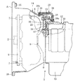
図1を参照すると、本発明に係るブリーザ装置を含む変速機の全体構成図の一部が示されている。
同図に示すように、本実施例では変速機は例えばオートマチックトランスミッション(以下、単にトランスミッションともいう)1であり、トランスミッション1は図示しないエンジンに接続されている。
Hereinafter, embodiments of the present invention will be described with reference to the drawings.
Referring to FIG. 1, a part of an overall configuration diagram of a transmission including a breather device according to the present invention is shown.
As shown in the figure, in this embodiment, the transmission is, for example, an automatic transmission (hereinafter simply referred to as a transmission) 1, and the transmission 1 is connected to an engine (not shown).
詳しくは、エンジンのクランクシャフト2と一体をなすドライブプレート4がトルクコンバータ(継手機構)6に取付ボルト7によって連結され、トルクコンバータ6が当該トルクコンバータ6内部の図示しないタービンライナと一体をなすインプットシャフト8を介してトランスミッションギヤユニット(変速機構であって、以下、単にギヤユニットともいう)10に接続されている。なお、エンジンのクランクシャフト2からの回転駆動力をトルクコンバータ6を介してギヤユニット10へ伝達する構成は公知であり、詳細についてはここでは説明を省略する。
Specifically, a
ギヤユニット10は、トランスミッションオイル等が外部に漏れないように気密に成形されたトランスミッションケース(以下、単にケースともいう)12に収納されている。
トルクコンバータ6は中空の略円錐台形状をしたコンバータハウジング(以下、単にハウジングともいう)14に収納されている。ハウジング14の一端はケース12に複数の取付ボルト13によって密接され、他端はエンジンに複数の取付ボルト15によって密接されている。ただし、図では取付ボルト13、15は代表して1つのみ記載されている。また、ハウジング14のエンジンとの接合面Aの下部には、ハウジング14の内部空間を大気開放するとともにハウジング14内に浸入または漏洩する液体を排出する排出孔(大気開放手段)18が設けられている。
The
The
ハウジング14内部のケース12とトルクコンバータ6との間には、インプットシャフト8に外嵌されるとともにケース12に取付ボルト17により密接されて円盤状のオイルポンプ16が設けられている。また、ケース12の下側にはオイルパン19が設けられている。
ケース12のハウジング14との接合面Bの上部近傍には、ケース12の内部とハウジング14内部とを連通する本発明に係るブリーザ機構20が形成されている。
A disc-
A
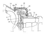
図2を参照すると、ブリーザ機構20の要部拡大図が示されており、以下図2に基づき本発明に係るブリーザ機構20の詳細について説明する。
ケース12には、接合面Bの上部に当該接合面Bに沿うようにしてラビリンス構造を有するブリーザ室22が形成されている。ブリーザ室22の下部にはブリーザ室22とケース12内部とを連通させるブリーザ通路24が、ブリーザ室22の上部にはブリーザ室22とケース外部とを連通するブリーザ通路26がそれぞれ穿設されている。
Referring to FIG. 2, an enlarged view of a main part of the
In the
ブリーザ通路26の外部側には例えば樹脂でできたブリーザホース(管部材、ブリーザ通路)28の一端が、継手28aを介してブリーザホース28の内部とブリーザ通路26とを連通するように接続されている。そして、ブリーザホース28はケース12、ハウジング14の上側を跨ぐように延び、ブリーザホース28の他端は、ハウジング14上部に穿設された孔30に、継手28bを介してブリーザホース28の内部とハウジング14の内部空間とが連通するように接続されている。なお、図示するように、孔30と上記排出孔18とは互いに離間するように設けられている。
One end of a breather hose (tube member, breather passage) 28 made of, for example, resin is connected to the outside of the
このように、本発明に係るブリーザ機構20では、ケース12の内部空間とハウジング14の内部空間とが、ブリーザ通路24、ブリーザ室22、ブリーザ通路26、ブリーザホース28を介して連通している。
以下、このように構成された本発明に係る変速機のブリーザ装置の作用について説明する。
As described above, in the
The operation of the breather device for a transmission according to the present invention configured as described above will be described below.
排出孔18により大気開放されているハウジング14の内部空間は常に外部の圧力、即ち大気圧と同じに保たれている一方、ケース12は気密な構成のため、ケース12内部の温度が上昇するとケース12内部の圧力も上昇する。ケース12内部の圧力が上昇し、ハウジング14内部の圧力、即ち大気圧との間に圧力差が生じると、ケース12内部の空気は図2の矢印のようにブリーザ通路24からブリーザ室22、ブリーザ通路26、ブリーザホース28の内部を通ってハウジング14内部に排出される。そして、当該ケース12内部の空気は、最終的にはハウジング14の排出孔18から外部に排出される。
While the internal space of the
この際、ケース12内部の空気にはギヤユニット10を潤滑するためのトランスミッションオイルの飛沫が混在しているが、当該オイルの飛沫はラビリンス構造であるブリーザ室22を通ることにより外部に排出されることなく滴化され、ケース12内部に良好に回収される。
一方、ケース12内部の圧力が減少した場合には、ハウジング14内部の空気は図2の矢印とは逆の方向に流れ、ブリーザホース28を通りケース12内部に吸い込まれることとなる。
At this time, splashes of transmission oil for lubricating the
On the other hand, when the pressure inside the
このように、ケース12内部の空気がブリーザホース28を通ってハウジング14内部と行き来することになると、例えば、車両を水等で洗浄する際に水等がトランスミッション1にかかったとしても、当該水等がブリーザ機構20を介してケース12内部に浸入することが防止される。
つまり、本発明に係る変速機のブリーザ装置では、ハウジング14内部という直接水等がかからないところにブリーザ機構20の出口を設け、さらに当該出口である孔30と排出孔18とを互いに離間するようにしているので、排出孔18から浸入した水等が孔30周囲に到達することがなく、トランスミッションケース12内への水等の浸入を防ぐことができる。
As described above, when the air inside the
That is, in the breather device for a transmission according to the present invention, the outlet of the
これにより、水等のトランスミッションケース12内への浸入によるトランスミッションオイルの劣化を防ぐことができ、ひいてはギヤユニット10の機能低下や故障を防ぐことができる。
また、ここでは、ケース12の内部空間とハウジング14の内部空間とをブリーザホース28を用いて連通するようにしているため、既存の材料を用いた容易な構成でブリーザ通路を形成することができ、コストを抑えることができる。
As a result, it is possible to prevent deterioration of the transmission oil due to intrusion of water or the like into the
Here, since the internal space of the
また、ブリーザ機構20にラビリンス構造を有するブリーザ室22を設けるようにしているため、ケース12内部の空気に含まれるオイルを外部に排出することなく良好に回収することができる。
さらに、ハウジング14の下部に排出孔18を設けるようにしているので、ハウジング14内部のエア抜きを良好に行うことでハウジング14内部の圧力を常に外部と同じ大気圧に保つことができ、上昇したケース12内部の圧力を確実にハウジング14内部に逃がすことができる。また、トルクコンバータ6やオイルポンプ16等のオイル漏れ等をここで確認することもできる。
Further, since the
Further, since the
以上で本発明に係る変速機のブリーザ装置の実施形態についての説明を終えるが、実施形態は上記実施形態に限られるものではない。
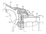
例えば、上記実施形態では、ブリーザホース28を用いたブリーザ機構20を設ける構成としたが、これに限られるものではなく、ケース12内部とハウジング14内部とが連通する構成であればよい。即ち、他の実施形態として、図3に示すように、ケース12及びハウジング14と一体となるブリーザ通路32、34を形成するようにしてもよい。または、他の実施形態として、図4に示すように、ブリーザ室22上部からオイルポンプ16のハウジング部材の一部を貫通するように通路36を穿設するようにしてもよい。
Although the description of the embodiment of the breather device for a transmission according to the present invention is finished above, the embodiment is not limited to the above embodiment.
For example, in the above embodiment, the
また、ブリーザ機構20の位置も上記実施形態のように接合面Bの上部近傍に限るものではない。この場合、ブリーザ機構20の出口である孔30と排出孔18とが互いに離間しているのが好ましい。
また、上記実施形態では、変速機をオートマチックトランスミッション1としたが、これに限るものではなく、変速機は例えばマニュアルトランスミッションでも構わない。この場合には、上記実施形態のトルクコンバータハウジング14がクラッチのハウジングに置き換わる。
Further, the position of the
In the above embodiment, the transmission is the automatic transmission 1, but the transmission is not limited to this, and the transmission may be a manual transmission, for example. In this case, the
また、上記実施形態では、樹脂でできたブリーザホース28を使用するようにしたが、これに限るものではなく、ゴム製のホースや金属のパイプ等を用いてもよい。
また、上記実施形態では、ハウジング14の大気開放手段を排出孔18で実現したが、ハウジング14内部の圧力が外部の圧力と常に同じになるような構成であればよい。
In the above embodiment, the
Moreover, in the said embodiment, although the air release means of the
1 オートマチックトランスミッション(変速機)
6 トルクコンバータ(継手機構)
10 トランスミッションギヤユニット(変速機構)
12 トランスミッションケース(ケース)
14 トルクコンバータハウジング(ハウジング)
16 オイルポンプ
18 排出孔(大気開放手段)
20 ブリーザ装置
22 ブリーザ室
24、26、32、34、36 ブリーザ通路
28 ブリーザホース(管部材、ブリーザ通路)
30 孔
1 Automatic transmission (transmission)
6 Torque converter (joint mechanism)
10 Transmission gear unit (transmission mechanism)
12 Transmission case (case)
14 Torque converter housing (housing)
16
20
30 holes
Claims (5)
該変速機構を収納するケースと、
前記内燃機関と前記変速機構との間に介装される継手機構と、
前記継手機構を収納し、前記内燃機関と前記ケースとの間に介装されるハウジングと、
前記ケースの内部空間と前記ハウジングの内部空間とを連通するブリーザ通路と、
該ブリーザ通路の前記ハウジング側の出口から離間した位置に設けられ、前記ハウジングの内部空間を大気開放する大気開放手段と、
を備えたことを特徴とする変速機のブリーザ装置。 A speed change mechanism for shifting and outputting the rotational driving force of the internal combustion engine;
A case for housing the transmission mechanism;
A joint mechanism interposed between the internal combustion engine and the speed change mechanism;
A housing that houses the joint mechanism and is interposed between the internal combustion engine and the case;
A breather passage communicating the internal space of the case with the internal space of the housing;
Air release means provided at a position spaced apart from the outlet of the breather passage on the housing side, and opening the internal space of the housing to the atmosphere;
A breather device for a transmission.
Priority Applications (1)
| Application Number | Priority Date | Filing Date | Title |
|---|---|---|---|
| JP2004105986A JP2005291326A (en) | 2004-03-08 | 2004-03-31 | Breather device of transmission |
Applications Claiming Priority (2)
| Application Number | Priority Date | Filing Date | Title |
|---|---|---|---|
| JP2004064118 | 2004-03-08 | ||
| JP2004105986A JP2005291326A (en) | 2004-03-08 | 2004-03-31 | Breather device of transmission |
Publications (1)
| Publication Number | Publication Date |
|---|---|
| JP2005291326A true JP2005291326A (en) | 2005-10-20 |
Family
ID=35324489
Family Applications (1)
| Application Number | Title | Priority Date | Filing Date |
|---|---|---|---|
| JP2004105986A Pending JP2005291326A (en) | 2004-03-08 | 2004-03-31 | Breather device of transmission |
Country Status (1)
| Country | Link |
|---|---|
| JP (1) | JP2005291326A (en) |
Cited By (3)
| Publication number | Priority date | Publication date | Assignee | Title |
|---|---|---|---|---|
| WO2018099654A1 (en) * | 2016-11-30 | 2018-06-07 | Zf Friedrichshafen Ag | Drive assembly for a vehicle, and vehicle comprising the drive assembly |
| CN110219965A (en) * | 2019-03-25 | 2019-09-10 | 陕西法士特齿轮有限责任公司 | A kind of flush type ventilation plug structure and method for exhausting |
| JP7201644B2 (en) | 2020-06-30 | 2023-01-10 | ダイハツ工業株式会社 | Breather structure |
Citations (1)
| Publication number | Priority date | Publication date | Assignee | Title |
|---|---|---|---|---|
| JPS5993565A (en) * | 1982-11-18 | 1984-05-30 | Aisin Seiki Co Ltd | Air vent device within case chamber of speed change gear |
-
2004
- 2004-03-31 JP JP2004105986A patent/JP2005291326A/en active Pending
Patent Citations (1)
| Publication number | Priority date | Publication date | Assignee | Title |
|---|---|---|---|---|
| JPS5993565A (en) * | 1982-11-18 | 1984-05-30 | Aisin Seiki Co Ltd | Air vent device within case chamber of speed change gear |
Cited By (9)
| Publication number | Priority date | Publication date | Assignee | Title |
|---|---|---|---|---|
| WO2018099654A1 (en) * | 2016-11-30 | 2018-06-07 | Zf Friedrichshafen Ag | Drive assembly for a vehicle, and vehicle comprising the drive assembly |
| CN109996977A (en) * | 2016-11-30 | 2019-07-09 | Zf腓特烈斯哈芬股份公司 | Driving equipment for vehicle and the vehicle with the driving equipment |
| KR20190087574A (en) * | 2016-11-30 | 2019-07-24 | 젯트에프 프리드리히스하펜 아게 | A vehicle drive assembly, and a vehicle equipped with the drive assembly |
| US11226031B2 (en) | 2016-11-30 | 2022-01-18 | Zf Friedrichshafen Ag | Drive assembly for a vehicle, and vehicle comprising the drive assembly |
| CN109996977B (en) * | 2016-11-30 | 2022-05-31 | Zf腓特烈斯哈芬股份公司 | Drive device for vehicle and vehicle having the same |
| KR102419463B1 (en) * | 2016-11-30 | 2022-07-12 | 젯트에프 프리드리히스하펜 아게 | A drive assembly for a vehicle, and a vehicle equipped with the drive assembly |
| CN110219965A (en) * | 2019-03-25 | 2019-09-10 | 陕西法士特齿轮有限责任公司 | A kind of flush type ventilation plug structure and method for exhausting |
| CN110219965B (en) * | 2019-03-25 | 2024-02-06 | 陕西法士特齿轮有限责任公司 | Buried vent plug structure and exhaust method |
| JP7201644B2 (en) | 2020-06-30 | 2023-01-10 | ダイハツ工業株式会社 | Breather structure |
Similar Documents
| Publication | Publication Date | Title |
|---|---|---|
| US8882480B2 (en) | Oil pump with air vent structure | |
| US9017195B2 (en) | Arrangement for lube oil supply a chain drive driving a transmission oil pump arranged offset the axis of a torque converter | |
| JP4539383B2 (en) | Power transmission device control unit mounting structure | |
| US10792598B2 (en) | Breather | |
| KR100892695B1 (en) | Oil pump of automatic transmission | |
| JPS63246557A (en) | Oil pump of automatic transmission | |
| JP2005291326A (en) | Breather device of transmission | |
| CN106352055A (en) | Automobile gearbox air exhausting device | |
| JP2003214530A (en) | Breather structure of transfer | |
| JP2014227984A (en) | Structure of water pump | |
| JP4412607B2 (en) | Hydraulic hose protection structure | |
| WO2003004909A1 (en) | Breather device for speed-change devices | |
| JP2013061034A (en) | Power transmission device for vehicle | |
| JP2006275165A (en) | Transmission | |
| JP2008180313A (en) | Breather device | |
| KR20080014368A (en) | Transmission for mobile | |
| CN210141311U (en) | Breather device for transmission | |
| JP7083578B2 (en) | Oil pump | |
| KR101789574B1 (en) | Coupling device | |
| KR101827056B1 (en) | Method for Automatic Transmission Oil Level Checking and Oil Exchange | |
| JP2002213583A (en) | Oil feeding device for transmission | |
| KR200174846Y1 (en) | Torque converter for automatic transmission | |
| JP2524721B2 (en) | Lock-up automatic transmission | |
| JP6522988B2 (en) | Transmission for industrial vehicles | |
| KR20040050991A (en) | Air breather for Axle |
Legal Events
| Date | Code | Title | Description |
|---|---|---|---|
| A621 | Written request for application examination |
Effective date: 20061227 Free format text: JAPANESE INTERMEDIATE CODE: A621 |
|
| A977 | Report on retrieval |
Free format text: JAPANESE INTERMEDIATE CODE: A971007 Effective date: 20100127 |
|
| A131 | Notification of reasons for refusal |
Effective date: 20100203 Free format text: JAPANESE INTERMEDIATE CODE: A131 |
|
| A02 | Decision of refusal |
Free format text: JAPANESE INTERMEDIATE CODE: A02 Effective date: 20100609 |