JP2005291146A - Temperature detecting device for cylinder pressure sensor, detecting device for cylinder pressure using it, and control device for internal combustion engine - Google Patents
Temperature detecting device for cylinder pressure sensor, detecting device for cylinder pressure using it, and control device for internal combustion engine Download PDFInfo
- Publication number
- JP2005291146A JP2005291146A JP2004109769A JP2004109769A JP2005291146A JP 2005291146 A JP2005291146 A JP 2005291146A JP 2004109769 A JP2004109769 A JP 2004109769A JP 2004109769 A JP2004109769 A JP 2004109769A JP 2005291146 A JP2005291146 A JP 2005291146A
- Authority
- JP
- Japan
- Prior art keywords
- cylinder pressure
- temperature
- drift
- pressure sensor
- internal combustion
- Prior art date
- Legal status (The legal status is an assumption and is not a legal conclusion. Google has not performed a legal analysis and makes no representation as to the accuracy of the status listed.)
- Granted
Links
Images


Landscapes
- Combined Controls Of Internal Combustion Engines (AREA)
Abstract
Description
本発明は、内燃機関の筒内圧を検出するための筒内圧センサの温度を検知する筒内圧センサの温度検知装置、ならびにこれを用いた筒内圧の検出装置および内燃機関の制御装置に関する。 The present invention relates to an in-cylinder pressure sensor temperature detecting device for detecting the temperature of an in-cylinder pressure sensor for detecting an in-cylinder pressure of an internal combustion engine, and an in-cylinder pressure detection device and an internal combustion engine control device using the same.
本願に関連する従来の技術として、例えば特許文献1に開示されたものが知られている。この特許文献1は、筒内圧センサの故障を、筒内圧センサの温度に基づいて判定する故障判定装置を開示している。筒内圧センサは、圧電素子を備え、内燃機関の各気筒に、燃焼室に臨むように設けられている。この故障判定装置では、筒内圧センサを代表する温度が、内燃機関のシンリンダブロック内のウォータージャケットを流れる冷却水の温度を代用して検出される。あるいは、筒内圧センサの温度が、温度センサによって直接、検出される。そして、検出された筒内圧センサの温度が所定の低温域および高温域にあるか否かを判別するとともに、低温域および高温域においてそれぞれ得られた筒内圧センサの2つの検出値(低温側検出値P1、高温側検出値P2)に基づいて、筒内圧センサの故障を判定する。
As a conventional technique related to the present application, for example, one disclosed in
この故障判定の手法は、筒内圧センサが温度に応じて大きくドリフトするというドリフト特性と、そのドリフト量が筒内圧センサの劣化の度合いに応じて異なるという特性を利用したものである。このような筒内圧センサの特性に基づき、故障判定装置では、筒内圧センサが正常であれば、そのドリフト特性により、高温側検出値P2が低温側検出値P1よりもはるかに大きくなり、両者の比P2/P1が大きな値になるべきであるという観点から、この比P2/P1が所定値よりも小さいときに、筒内圧センサが故障していると判定される。 This failure determination method utilizes a drift characteristic that the in-cylinder pressure sensor drifts greatly depending on the temperature and a characteristic that the amount of drift varies depending on the degree of deterioration of the in-cylinder pressure sensor. Based on the characteristics of the in-cylinder pressure sensor, in the failure determination device, if the in-cylinder pressure sensor is normal, the high temperature side detection value P2 becomes much larger than the low temperature side detection value P1 due to the drift characteristic, From the viewpoint that the ratio P2 / P1 should be a large value, it is determined that the in-cylinder pressure sensor has failed when the ratio P2 / P1 is smaller than a predetermined value.
上述した従来の故障判定装置では、筒内圧センサの温度として、内燃機関の冷却水温が代用されている。しかし、筒内圧センサが燃焼室に臨むように近接して配置されるのに対し、冷却水は、シリンダブロック内のウォータージャケットを流れるため、内燃機関の運転状態によっては、冷却水温は筒内圧センサの実際の温度と必ずしも一致しない。例えば、内燃機関の冷間始動時においては、燃焼室に近接して配置された筒内圧センサの温度は比較的速く上昇するのに対し、冷却水温の上昇速度が小さいため、両温度間のずれが大きくなる。その結果、この故障判定装置では、筒内圧センサの温度を精度良く検知することができず、その検知結果に基づく故障判定も適正に行えなくなってしまう。 In the conventional failure determination apparatus described above, the cooling water temperature of the internal combustion engine is used as the temperature of the in-cylinder pressure sensor. However, while the in-cylinder pressure sensor is disposed close to the combustion chamber, the cooling water flows through the water jacket in the cylinder block. Therefore, depending on the operating state of the internal combustion engine, the cooling water temperature may be Does not necessarily match the actual temperature. For example, when the internal combustion engine is cold-started, the temperature of the in-cylinder pressure sensor disposed in the vicinity of the combustion chamber rises relatively quickly, whereas the rate of increase in the cooling water temperature is small. Becomes larger. As a result, this failure determination device cannot accurately detect the temperature of the in-cylinder pressure sensor, and failure determination based on the detection result cannot be performed properly.
また、筒内圧センサの温度を直接、検出する場合には、そのための専用の温度センサが必要になるため、冷却水温で代用する場合よりも製造コストが上昇する。また、筒内圧センサは通常、比較的狭いシリンダヘッドに点火プラグとともに設けられることが多いため、内燃機関の機種によっては、スペースの制約から、温度センサの取付けが困難な場合もある。 Further, when the temperature of the in-cylinder pressure sensor is directly detected, a dedicated temperature sensor for that purpose is required, and therefore the manufacturing cost is higher than when the cooling water temperature is substituted. Further, since the in-cylinder pressure sensor is usually provided with a spark plug in a relatively narrow cylinder head, it may be difficult to attach the temperature sensor due to space restrictions depending on the model of the internal combustion engine.
本発明は、このような課題を解決するためになされたものであり、筒内圧センサの温度を、温度センサを用いることなく、検知することができる筒内圧センサの温度検知装置を提供することを目的とする。また、検知された筒内圧センサの温度を用いて、筒内圧を精度良く検出できる筒内圧の検出装置、および内燃機関を適切に制御できる内燃機関の制御装置を提供することを目的とする。 The present invention has been made to solve such a problem, and provides a temperature detection device for an in-cylinder pressure sensor that can detect the temperature of the in-cylinder pressure sensor without using the temperature sensor. Objective. It is another object of the present invention to provide an in-cylinder pressure detecting device that can accurately detect the in-cylinder pressure using the detected temperature of the in-cylinder pressure sensor and an internal combustion engine control device that can appropriately control the internal combustion engine.
上記の目的を達成するため、請求項1に係る発明は、内燃機関3の気筒3a内の圧力を筒内圧pcylとして検出するための筒内圧センサ4の温度TempPSを検知する筒内圧センサの温度検知装置であって、筒内圧センサ4のドリフトを表すドリフトパラメータ(実施形態における(以下、本項において同じ)ドリフト量driftの統計処理値driftave)を演算するドリフトパラメータ演算手段(ECU2、図2、7および12の各ステップ4)と、演算されたドリフトパラメータに基づいて、筒内圧センサ4の温度TempPSを検知する温度検知手段(ECU2、図3のステップ13)と、を備えることを特徴とする。
In order to achieve the above object, the invention according to
この筒内圧センサの温度検知装置によれば、筒内圧センサのドリフトを表すドリフトパラメータを演算するとともに、演算されたドリフトパラメータに基づいて、筒内圧センサの温度を検知する。前述したように、筒内圧センサは、その圧電素子などと併せて設けられる絶縁抵抗の抵抗値が温度に応じて変化することに起因し、その出力値が温度に応じてドリフトするという特性を有し、両者の間には一定の関係がある。本発明は、このような温度と一定の関係を有するドリフト特性を、逆に筒内圧センサの温度検知に利用したものであり、ドリフトを表すドリフトパラメータを演算するとともに、演算したドリフトパラメータに基づいて、筒内圧センサの温度を検知することができる。また、演算したドリフトパラメータのみに基づいて、筒内圧センサの温度を検知できるので、これを直接、検出する温度センサは不要になる。したがって、その分、製造コストを削減できるとともに、温度センサを設置する際のレイアウト上の制約を受けることがなく、本発明を、内燃機関の機種などにかかわらず広く適用することができる。 According to the temperature detection device for the in-cylinder pressure sensor, the drift parameter representing the drift of the in-cylinder pressure sensor is calculated, and the temperature of the in-cylinder pressure sensor is detected based on the calculated drift parameter. As described above, the in-cylinder pressure sensor has a characteristic that the output value drifts according to the temperature because the resistance value of the insulation resistance provided together with the piezoelectric element changes according to the temperature. However, there is a certain relationship between them. In the present invention, the drift characteristic having a certain relationship with the temperature is used for detecting the temperature of the in-cylinder pressure sensor, and the drift parameter representing the drift is calculated, and based on the calculated drift parameter. The temperature of the in-cylinder pressure sensor can be detected. Further, since the temperature of the in-cylinder pressure sensor can be detected based only on the calculated drift parameter, a temperature sensor that directly detects this is not necessary. Therefore, the manufacturing cost can be reduced accordingly, and the layout is not restricted when the temperature sensor is installed, and the present invention can be widely applied regardless of the model of the internal combustion engine.
請求項2に係る発明は、請求項1に記載の筒内圧センサの温度検知装置において、ドリフトパラメータ演算手段は、ドリフトパラメータを逐次統計処理によって演算する(図2、図7および図12)ことを特徴とする。 According to a second aspect of the present invention, in the temperature detection device for an in-cylinder pressure sensor according to the first aspect, the drift parameter calculating means calculates the drift parameter by sequential statistical processing (FIGS. 2, 7, and 12). Features.
この構成によれば、ドリフトパラメータを逐次統計処理によって演算するので、ノイズや筒内圧の確率的変化による影響を除去することができるため、筒内圧センサの温度の検知精度を維持しながら、演算頻度を低減することができる。 According to this configuration, since the drift parameter is sequentially calculated by statistical processing, it is possible to eliminate the influence of noise and the stochastic change in the in-cylinder pressure, so the calculation frequency is maintained while maintaining the temperature detection accuracy of the in-cylinder pressure sensor. Can be reduced.
請求項3に係る発明は、請求項1または2に記載の筒内圧センサの温度検知装置において、筒内圧センサ4のドリフトをリセットするリセット手段(リセット回路2b)をさらに備え、ドリフトパラメータ演算手段は、リセット手段によるリセットの前後において検出された筒内圧(リセット前筒内圧pcylpre、リセット後筒内圧pcylpost、筒内圧変化量Δpcyl)に基づいて、ドリフトパラメータを演算することを特徴とする。
The invention according to
この構成によれば、筒内圧センサのドリフトは、リセット手段によってリセットされる。このため、そのリセット前後において検出された筒内圧、例えば両者の偏差は、ドリフトの状況を良好に表す。本発明によれば、そのようなリセット前後における筒内圧センサの検出値に基づいて、ドリフトパラメータを演算するので、ドリフトパラメータにドリフトの状況を良好に反映させることができ、したがって、それに基づいて検知される筒内圧センサの温度の検知精度を高めることができる。 According to this configuration, the drift of the in-cylinder pressure sensor is reset by the reset means. For this reason, the in-cylinder pressure detected before and after the resetting, for example, the deviation between the two, represents the state of drift well. According to the present invention, since the drift parameter is calculated based on the detection value of the in-cylinder pressure sensor before and after such resetting, the drift condition can be reflected well in the drift parameter, and therefore the detection is performed based on the drift parameter. The detection accuracy of the temperature of the in-cylinder pressure sensor can be increased.
請求項4に係る発明は、請求項1または2に記載の筒内圧センサの温度検知装置において、筒内圧センサ4のドリフトを補正するためのドリフト補正量pcyl_compを設定するドリフト補正量設定手段(ドリフト補正回路2c)をさらに備え、ドリフトパラメータ演算手段は、ドリフト補正手段で設定されたドリフト補正量pcyl_compに基づいて、ドリフトパラメータを演算することを特徴とする。
According to a fourth aspect of the present invention, in the temperature detection device for the in-cylinder pressure sensor according to the first or second aspect, drift correction amount setting means (drift for setting a drift correction amount pcyl_comp for correcting drift of the in-
この構成によれば、筒内圧センサのドリフトは、ドリフト補正量設定手段によって設定されたドリフト補正量によって補正される。このため、設定されたドリフト補正量は、ドリフトの状況を良好に表す。本発明によれば、そのようなドリフト補正量に基づいて、ドリフトパラメータを演算するので、ドリフトパラメータにドリフトの状況を良好に反映させることができ、したがって、それに基づいて検知される筒内圧センサの温度の検知精度を高めることができる。 According to this configuration, the drift of the in-cylinder pressure sensor is corrected by the drift correction amount set by the drift correction amount setting means. For this reason, the set drift correction amount represents the state of drift well. According to the present invention, since the drift parameter is calculated based on such a drift correction amount, it is possible to satisfactorily reflect the state of the drift in the drift parameter, and accordingly, the in-cylinder pressure sensor detected based on the drift parameter can be reflected. Temperature detection accuracy can be increased.
請求項5に係る発明は、請求項1ないし4のいずれかに記載の筒内圧センサの温度検知装置において、内燃機関3の運転状態(エンジン水温Tw)を検出する運転状態検出手段(エンジン水温センサ23)と、検出された内燃機関の運転状態に応じて、温度検知手段で検知された筒内圧センサ4の温度TempPSを補正する温度補正手段(ECU2、図14)と、をさらに備えることを特徴とする。
According to a fifth aspect of the present invention, in the in-cylinder pressure sensor temperature detecting device according to any one of the first to fourth aspects, the operating state detecting means (engine water temperature sensor) for detecting the operating state (engine water temperature Tw) of the
この構成によれば、温度検知手段によって検知された筒内圧センサの温度が、検出された内燃機関の運転状態に応じて補正される。前述したように、本発明では、演算したドリフトパラメータに基づき、筒内圧センサの温度を推定によって検知するので、内燃機関の運転状態によっては、検知した筒内圧センサの温度が、実際の温度に対してずれる可能性がある。例えば、内燃機関が極端に低いあるいは高い温度から始動されるような場合には特に、検知温度の初期値が実際の温度と整合しにくい。この発明によれば、ドリフトパラメータに基づいて検知された筒内圧センサの温度を、検出された内燃機関の実際の運転状態に応じて補正するので、上記のような実際の温度とのずれを解消でき、検知精度をさらに向上させることができる。 According to this configuration, the temperature of the in-cylinder pressure sensor detected by the temperature detection unit is corrected according to the detected operating state of the internal combustion engine. As described above, in the present invention, the temperature of the in-cylinder pressure sensor is detected by estimation based on the calculated drift parameter. Therefore, depending on the operating state of the internal combustion engine, the detected temperature of the in-cylinder pressure sensor may be lower than the actual temperature. There is a possibility of slipping. For example, especially when the internal combustion engine is started from an extremely low or high temperature, the initial value of the detected temperature is difficult to match the actual temperature. According to the present invention, since the temperature of the in-cylinder pressure sensor detected based on the drift parameter is corrected according to the detected actual operating state of the internal combustion engine, the deviation from the actual temperature as described above is eliminated. And detection accuracy can be further improved.
また、前記目的を達成するため、請求項6に係る筒内圧の検出装置は、請求項1ないし5のいずれかに記載の筒内圧センサの温度検知装置によって検知された筒内圧センサ4の温度TempPSに応じて、検出された筒内圧pcylを補正する筒内圧補正手段(ECU2、図16)を備えることを特徴とする。
In order to achieve the above object, the in-cylinder pressure detecting device according to
この筒内圧の検出装置によれば、請求項1ないし5のいずれかに記載の温度検知装置によって検知された筒内圧センサの温度に応じて、検出された筒内圧を補正するので、筒内圧センサの検出値を適切に温度補償することによって、温度によるドリフトの影響を排除でき、したがって、筒内圧の検出精度を高めることができる。
According to this in-cylinder pressure detection device, the detected in-cylinder pressure is corrected in accordance with the temperature of the in-cylinder pressure sensor detected by the temperature detection device according to any one of
また、前記目的を達成するため、請求項7に係る内燃機関の制御装置は、内燃機関3を制御するための制御入力(燃料噴射量Tout)を設定する制御入力設定手段(ECU2、図18のステップ81)と、請求項1ないし5のいずれかに記載の筒内圧センサの温度検知装置によって検知された筒内圧センサ4の温度TempPSに応じて、設定された制御入力を補正する制御入力補正手段(ECU2、図18のステップ82、83)と、を備えることを特徴とする。
In order to achieve the above object, a control apparatus for an internal combustion engine according to
この内燃機関の制御装置によれば、請求項1ないし5のいずれかに記載の温度検知装置によって検知された筒内圧センサの温度に応じて、内燃機関を制御するための制御入力を補正する。筒内圧センサは通常、燃焼室に近い部位に配置されるため、その温度は、例えば内燃機関の冷却水温などよりも、燃焼室の温度を良好に表す。したがって、筒内圧センサの温度に応じて制御入力を補正することによって、燃焼室の温度をより良好に反映させながら、内燃機関の制御をより適切に行うことができる。
According to the control device for an internal combustion engine, the control input for controlling the internal combustion engine is corrected according to the temperature of the in-cylinder pressure sensor detected by the temperature detection device according to any one of
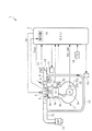
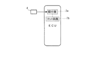
以下、図面を参照しながら、本発明の実施形態を詳細に説明する。図1〜図4は、第1実施形態を示している。図1に示す内燃機関(以下「エンジン」という)3は、例えば車両(図示せず)に搭載された4気筒(1つのみ図示)タイプのものであり、各気筒3aのピストン3bとシリンダヘッド3cの間には、燃焼室3dが形成されている。シリンダヘッド3cには、筒内圧センサ4、点火プラグ5、吸気弁6および排気弁7が、燃焼室3dに臨むように取り付けられている。
Hereinafter, embodiments of the present invention will be described in detail with reference to the drawings. 1 to 4 show a first embodiment. An internal combustion engine (hereinafter referred to as “engine”) 3 shown in FIG. 1 is of, for example, a four-cylinder (only one shown) type mounted on a vehicle (not shown), and a
筒内圧センサ4は、例えば点火プラグ5と一体型の圧電素子タイプのものであり、点火プラグ5とともにシリンダヘッド3cに固定されている。筒内圧センサ4は、気筒3a内の燃焼室3dの圧力(以下「筒内圧」という)の変化に応じ、圧電素子が点火プラグ5とともに変位することによって、筒内圧の変化量を表す検出信号をECU2に出力する。この筒内圧センサ4の検出信号は、ECU2内の積分器2aによって積分され、それにより、筒内圧Pcylが求められる(検出される)。
The in-
点火プラグ5は、点火コイル(図示せず)を介して、点火時期Igtに応じたタイミングで高電圧が加えられることによって放電し、それにより、燃焼室3d内の混合気が燃焼される。点火プラグ5の点火時期Igtは、ECU2によって制御される。
The
吸気管8の吸気弁6よりもすぐ上流側には、燃料噴射弁(以下「インジェクタ」という)9が取り付けられている。インジェクタ9は、その開弁時に、高圧ポンプ(図示せず)で一定圧に加圧された燃料を、燃焼室3dに向けて噴射する。インジェクタ9の開弁時間すなわち燃料噴射量Toutは、ECU2によって制御される。
A fuel injection valve (hereinafter referred to as “injector”) 9 is attached immediately upstream of the
さらに、吸気管8には、スロットル弁10および吸気圧センサ20が設けられている。スロットル弁10には、モータやギヤ機構(いずれも図示せず)を含むアクチュエータ11が連結されている。アクチュエータ11をECU2からの駆動信号によって駆動することにより、スロットル弁10の開度(以下「スロットル弁開度」という)THが制御され、このスロットル弁開度THに応じて、燃焼室3dに供給される吸入空気量が制御される。スロットル弁開度THは、スロットル弁開度センサ21によって検出され、その検出信号はECU2に出力される。吸気圧センサ20は、吸気管8内のスロットル弁10よりも下流側の圧力を絶対圧として検出し、吸気管内絶対圧PBAを表す検出信号をECU2に出力する。
Further, the intake pipe 8 is provided with a
また、エンジン3のクランクシャフト3eには、マグネットロータ22aが取り付けられている。このマグネットロータ22aとMREピックアップ22bによって、クランク角センサ22が構成されている。クランク角センサ22は、クランクシャフト3eの回転に伴い、パルス信号であるCRK信号およびTDC信号を出力する。CRK信号は、所定のクランク角(例えば1゜)ごとに出力される。ECU2は、このCRK信号に基づき、エンジン3の回転数(以下「エンジン回転数」という)NEを求める。TDC信号は、各気筒のピストン3bが吸気行程開始時のTDC(上死点)付近の所定クランク角度位置にあることを表す信号であり、4気筒タイプの本例では、クランク角180゜ごとに出力される。
A
また、エンジン3の本体には、エンジン水温センサ23(運転状態検出手段)が取り付けられている。エンジン水温センサ23は、サーミスタなどで構成されており、エンジン3の本体内を循環する冷却水の温度をエンジン水温Twとして検出し、その検出信号をECU2に出力する。さらに、ECU2には、吸気温センサ24から、吸気温Taを表す検出信号が出力される。
An engine water temperature sensor 23 (operating state detection means) is attached to the main body of the
また、エンジン3の排気管12には、触媒装置13が設けられている。この触媒装置13は、NOx触媒と三元触媒を組み合わせたものである。触媒装置13は、エンジン3のリーンバーン運転時に、NOx触媒の還元作用によって、排ガス中のNOxを浄化するとともに、リーンバーン運転以外の運転時に、三元触媒の酸化還元作用によって、排ガス中のCO、HCおよびNOxを浄化する。
The
さらに、吸気管8のスロットル弁10よりも下流側と、排気管12の触媒装置13よりも上流側との間には、EGR管14が接続されている。このEGR管14を介して、エンジン3の排ガスの一部を吸気側に再循環させるEGR動作が行われる。EGR管14には、EGR制御弁15が設けられている。EGR制御弁15は、リニア電磁弁であり、そのバルブリフト量が制御されることによって、EGR量が制御される。EGR制御弁15のバルブリフト量は、バルブリフト量センサ(図示せず)によって検出され、その検出信号はECU2に出力される。ECU2は、エンジン3の運転状態に応じてEGR制御弁15の目標バルブリフト量を設定し、実際のバルブリフト量が目標バルブリフト量になるように、EGR制御弁15を制御する。
Furthermore, an
ECU2は、実施形態において、ドリフトパラメータ演算手段、温度検知手段、温度補正手段、筒内圧補正手段、制御入力設定手段、および制御入力補正手段を構成するものである。ECU2は、CPU、RAMおよびROM(いずれも図示せず)などから成るマイクロコンピュータで構成されており、前述した筒内圧センサ4および各種のセンサ20〜24の検出信号などに応じ、ROMに記憶された制御プログラムなどに基づいて、各種の演算処理を実行する。具体的には、筒内圧センサ4の検出結果に応じて、筒内圧センサ4の温度を検知するとともに、検知した筒内圧センサ4の温度に応じて、筒内圧センサ4の検出結果や、インジェクタ4の燃料噴射量Toutを補正するなどの処理を行う。
In the embodiment, the
図2および図3は、筒内圧センサ4の温度を検知するための処理を示す。図2の逐次統計処理は、筒内圧pcylのドリフト量driftを算出するとともに、このドリフト量driftに基づき、重み付き最小2乗法によって、筒内圧センサ4の温度検知に用いるドリフト量の統計処理値driftaveを、ドリフトパラメータとして演算するものである。本処理は、TDC信号およびCRK信号に基づき、例えばクランク角度720°ごと、すなわち1燃焼サイクルごとに、排気行程中の所定のクランク角度位置において実行される。
2 and 3 show a process for detecting the temperature of the in-
本処理ではまず、ステップ1(「S1」と図示。以下同じ)において、筒内圧センサ4の検出信号を積分することにより得られた筒内圧pcylとその前回値pcyl1との偏差(pcyl−pcyl1)を、筒内圧pcylのドリフト量driftとして算出する。このドリフト量driftは、1燃焼サイクル間の筒内圧pcylのドリフト量を表す。上述したように、本処理がエンジン3の排気行程中に実行されることにより、筒内圧pcylが、大気圧付近まで確実に低下し、安定しているタイミングで、サンプリングされるので、ドリフト量driftを適正に算出できる。次に、今回得られた筒内圧pcylを、前回値pcyl1にシフトする(ステップ2)。
In this process, first, in step 1 (illustrated as “S1”, the same applies hereinafter), the deviation (pcyl−pcyl1) between the in-cylinder pressure pcyl obtained by integrating the detection signal of the in-
次いで、次式(1)によって、係数kpdriftを算出する(ステップ3)。
kpdrift=pdrift/(1+pdrift) ・・・(1)
ここで、pdriftは、後述するステップ5で算出される可変ゲインであり、その初期値は0に設定される。
Next, the coefficient kpdrift is calculated by the following equation (1) (step 3).
kpdrift = pdrift / (1 + pdrift) (1)
Here, pdrift is a variable gain calculated in
次に、算出した係数kpdriftを用い、次式(2)によってドリフト量の統計処理値driftaveを算出する(ステップ4)。
driftave=driftave
+kpdrift×(drift−driftave)・・・(2)
これにより、統計処理値driftaveは、その時点でのドリフト量driftとの偏差(drift−driftave)が最小になるように、逐次、演算される。
Next, using the calculated coefficient kpdrift, the statistical processing value drifttab of the drift amount is calculated by the following equation (2) (step 4).
driftave = driftave
+ Kpdrift × (drift-driftave) (2)
As a result, the statistical processing value drifttab is sequentially calculated so that the deviation (drift-driftave) from the drift amount drift at that time is minimized.
次いで、ゲインpdriftを次式(3)によって算出し(ステップ5)、本処理を終了する。
pdrift=pdrift/avew
+(1−pdrift/(avew+pdrift)) ・・・(3)
ここで、avewは、固定の重みパラメータ(例えば0.991)である。
Next, the gain pdrift is calculated by the following equation (3) (step 5), and this process is terminated.
pdrive = pdrive / avew
+ (1-pdrift / (ave + pdrift)) (3)
Here, avew is a fixed weight parameter (for example, 0.991).
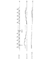
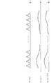
以上のような逐次統計処理により、筒内圧pcylがエンジン3の1燃焼サイクルを1周期として変化する(図8(a)参照)のに対し、1燃焼サイクル間の筒内圧pcylの偏差(pcyl−pcyl1)が、筒内圧pcylのドリフト量driftとして算出され(同図(b))、さらに、このドリフト量driftを逐次統計処理することによって、統計処理値driftaveが1燃焼サイクルごとに算出される(同図(c))。
By the sequential statistical processing as described above, the in-cylinder pressure pcyl changes with one combustion cycle of the
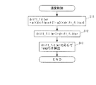
図3は、筒内圧センサ4の温度の検知処理を示す。本処理は、図2の逐次統計処理の実行間隔よりも長い所定時間(例えば1sec)ごとに実行される。本処理ではまず、ステップ11において、図2のステップ4で算出したドリフト量の統計処理値driftaveを、次式(4)により加重平均することによって、加重平均値drift_filterを算出する。
drift_filter=α×driftave
+(1−α)×drift_filter1 ・・・(4)
ここで、αは重み係数(0<α<1)、drift_filter1は、加重平均値drift_filterの前回値である。
FIG. 3 shows the temperature detection process of the in-
drift_filter = α × driftave
+ (1-α) × drift_filter1 (4)
Here, α is a weighting factor (0 <α <1), and drift_filter1 is the previous value of the weighted average value drift_filter.
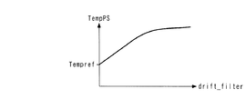
次に、今回算出された加重平均値drift_filterを、前回値drift_filter1にシフトする(ステップ12)。次いで、ステップ11で算出したドリフト量の加重平均値drift_filterに応じ、図4のテーブルを検索することによって、筒内圧センサ4の温度(以下「センサ温度」という)TempPSを算出し(ステップ13)、本処理を終了する。このテーブルは、筒内圧センサ4の温度とドリフト量との関係を測定した実験結果に基づくものであり、センサ温度TempPSは、加重平均値drift_filterが大きいほど、より大きな値に設定されている。また、その傾きは、加重平均値drift_filterが小さな範囲では比較的大きく、大きな範囲では比較的小さくなるように設定されている。なお、この実験により、実施形態で用いた筒内圧センサ4が、温度が所定温度Tempref(例えば25℃)未満では、温度に応じたドリフト量が無視できるほどに小さいという特性を有することが確認されたため、このテーブルは、温度TempPSが所定温度Tempref以上の範囲に対してのみ設定されている。
Next, the weighted average value drift_filter calculated this time is shifted to the previous value drift_filter1 (step 12). Next, the temperature of the in-cylinder pressure sensor 4 (hereinafter referred to as “sensor temperature”) TempPS is calculated by searching the table of FIG. 4 according to the weighted average value drift_filter calculated in step 11 (step 13). This process ends. This table is based on the experimental results of measuring the relationship between the temperature of the in-
以上のような温度検知処理により、燃焼サイクルごとに逐次演算される統計処理値driftaveを加重平均することによって、加重平均値drift_filterが、統計処理値driftaveに対して緩やかに変化するなまされた値として算出される(図9(d)参照)。また、センサ温度TempPSは、この加重平均値drift_filterに基づき、これと同様に緩やかに変化するように算出される(同図(e))。なお、図示の関係上、図9は、図8よりも非常に圧縮された時間スケールで描かれている。 The weighted average value drift_filter is a value obtained by performing a weighted average of the statistically processed value drifttab that is sequentially calculated for each combustion cycle by the temperature detection process as described above, so that the weighted average value drift_filter is gently changed with respect to the statistically processed value drifttab. (See FIG. 9D). Further, the sensor temperature TempPS is calculated so as to change gently based on this weighted average value drift_filter ((e) in the figure). 9 is drawn on a time scale that is much more compressed than that in FIG.
以上のように、本実施形態によれば、エンジン3の1燃焼サイクル間の筒内圧pcylの偏差(pcyl−pcyl1)を、筒内圧pcylのドリフト量driftとして算出し、このドリフト量driftに基づいて、その統計処理値driftaveをドリフトパラメータとして算出するとともに、この統計処理値driftaveに基づいて、センサ温度TempPSを算出する。このように、筒内圧センサ4のドリフトを表す統計処理値driftaveに基づいて、センサ温度TempPSを検知することができる。また、筒内圧pcylに応じて算出した統計処理値driftaveのみに基づいて、センサ温度TempPSを検知できるので、これを直接、検出する温度センサは不要になる。したがって、その分、製造コストを削減できるとともに、温度センサを設ける際のレイアウト上の制約を受けることがなく、本発明を、内燃機関の機種などにかかわらず広く適用することができる。さらに、統計処理値driftaveを逐次統計処理によって演算するので、ノイズや筒内圧pcylの確率的変化による影響を除去することができるため、センサ温度TepmPSの検知精度を維持しながら、演算頻度を低減することができる。
As described above, according to the present embodiment, the deviation (pcyl-pcyl1) of the in-cylinder pressure pcyl during one combustion cycle of the
次に、図5〜図7を参照しながら、本発明の第2実施形態について説明する。図5に示すように、本実施形態では、ECU2内に、積分器2aの積分によって得られた筒内圧pcylをリセットするためのリセット回路2b(リセット手段)が設けられている。このリセット回路2bは、エンジン3の1燃焼サイクル中の、例えば排気行程における所定のタイミングで(例えば図8の点A)、筒内圧pcylを基準値にリセットする。このリセット動作によって、筒内圧pcylに含まれるドリフト成分が1燃焼サイクルごとに除去され、その結果、図8(a)に示すような筒内圧pcylの波形が得られる。他の構成は、第1実施形態と同じである。
Next, a second embodiment of the present invention will be described with reference to FIGS. As shown in FIG. 5, in the present embodiment, a
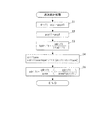
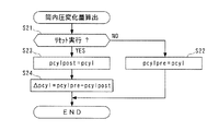
図6は、上記のリセット動作の前後における筒内圧pcylの変化量を算出する処理を示す。本処理は、1燃焼サイクルよりも非常に短い間隔で、所定のクランク角度(例えば1°)ごとに実行される。まず、ステップ21では、リセット回路2bによる筒内圧pcylのリセット動作が実行されたか否かを判別し、その答がNOのときには、そのときの筒内圧pcylをリセット前筒内圧pcylpreとして記憶する(ステップ22)。前記ステップ21の答がYESで、今回がリセット動作の実行直後に相当するときには、そのときの筒内圧pcylを、リセット後筒内圧pcylpostとして記憶する(ステップ23)。次いで、リセット前筒内圧pcylpreとリセット後筒内圧pcylpostとの偏差を、リセット動作の前後における筒内圧変化量Δpcylとして算出し(ステップ24)、本処理を終了する。
FIG. 6 shows processing for calculating the amount of change in the in-cylinder pressure pcyl before and after the reset operation. This process is executed for each predetermined crank angle (for example, 1 °) at intervals much shorter than one combustion cycle. First, in
図7は、本実施形態による逐次統計処理を示しており、第1実施形態(図2)のそれと同じ実行内容のステップについては、同じ番号を付している。本処理は、1燃焼サイクルごとに、例えば上記リセット動作の直後に実行される。本処理ではまず、上記のようにして算出した筒内圧変化量Δpcylを、筒内圧pcylのドリフト量driftとして設定する(ステップ31)。このドリフト量driftは、1燃焼サイクル中の筒内圧pcylのドリフト量を表す。以後の処理内容は、第1実施形態の場合とまったく同じである。すなわち、可変ゲインpdriftを用い、前記式(1)によって係数kpdriftを算出し(ステップ3)、ステップ31で求めたドリフト量driftと係数kpdriftを用い、前記式(2)によってドリフト量の統計処理値driftaveを算出する(ステップ4)とともに、可変ゲインpdriftを前記式(3)によって算出する(ステップ5)。そして、図示しないが、算出した統計処理値driftaveに基づき、図3とまったく同じ温度検知処理によって、センサ温度TempPSを算出する。以上の処理により、ドリフト量driftに基づき、統計処理値driftave、さらにはセンサ温度TempPSが、第1実施形態と同様にして求められる(図8および図9参照)。
FIG. 7 shows sequential statistical processing according to the present embodiment, and steps having the same execution contents as those of the first embodiment (FIG. 2) are assigned the same numbers. This process is executed every combustion cycle, for example, immediately after the reset operation. In this process, first, the in-cylinder pressure change amount Δpcyl calculated as described above is set as the drift amount drift of the in-cylinder pressure pcyl (step 31). This drift amount drift represents the drift amount of the in-cylinder pressure pcyl during one combustion cycle. Subsequent processing contents are exactly the same as those in the first embodiment. That is, the coefficient kpshift is calculated by the above equation (1) using the variable gain pdrift (step 3), and the drift amount statistical processing value is calculated by the above equation (2) using the drift amount drift and the coefficient kpdrift obtained in
以上のように、本実施形態によれば、リセット回路2bによる筒内圧pcylのリセット動作の前後における筒内圧変化量Δpcylを、筒内圧pcylのドリフト量driftとして算出し、このドリフト量driftに基づき、第1実施形態と同様にして、その統計処理値driftaveをドリフトパラメータとして算出するとともに、この統計処理値driftaveに基づいて、センサ温度TempPSを算出する。したがって、筒内圧センサ4のドリフトを表す統計処理値driftaveに基づいて、温度センサを用いることなく、センサ温度TempPSを検知できるなど、第1実施形態による前述した効果を同様に得ることができる。これに加えて、本実施形態では、筒内圧pcylのリセット動作の前後における筒内圧変化量Δpcylに基づいて、統計処理値driftaveを算出するので、この統計処理値driftaveにドリフトの状況を良好に反映させることができ、したがって、センサ温度TempPSの検知精度を高めることができる。
As described above, according to the present embodiment, the in-cylinder pressure change amount Δpcyl before and after the reset operation of the in-cylinder pressure pcyl by the
次に、図10〜図13を参照しながら、本発明の第3実施形態について説明する。図10に示すように、本実施形態では、ECU2内に、第2実施形態のリセット回路2bに代えて、筒内圧センサ4のドリフトを補正するためのドリフト補正回路2c(ドリフト補正量設定手段)が設けられている。他の構成は、第1実施形態と同じである。
Next, a third embodiment of the present invention will be described with reference to FIGS. As shown in FIG. 10, in this embodiment, in the
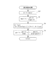
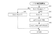
図11は、このドリフト補正回路2cにおいて実行されるドリフト補正量の算出処理を示す。本処理は、CRK信号の発生に同期して、所定のクランク角度(例えば1°)ごとに実行される。まず、ステップ41において、カウンタDcntの値が所定値Dsample(例えば720)に等しいか否かを判別する。このカウンタDcntは、ドリフト補正量の算出用の筒内圧pcylをサンプリングするタイミングを決定するためのものであり、後述するように、1燃焼サイクルごとに、吸気行程中の所定のクランク角度位置においてリセットされる。このステップ41の答がNOで、所定のクランク角度位置でないときには、カウンタDcntをインクリメントする(ステップ42)。
FIG. 11 shows a drift correction amount calculation process executed in the
一方、前記ステップ41の答がYESで、所定のクランク角度位置に相当するときには、カウンタDcntをリセットした(ステップ43)後、そのときにサンプリングされた筒内圧pcylと吸気管内絶対圧PBAとの偏差(pcyl−PBA)を、ドリフト値pdftとして算出する(ステップ44)。上述したように、pcyl値およびPBA値がともに吸気行程中にサンプリングされるので、このときの吸気管内絶対圧PBAは大気圧にほぼ等しく、したがって、両者の偏差として算出されるドリフト値pdftは、1燃焼サイクル中の筒内圧pcylのドリフト量を表す。 On the other hand, if the answer to step 41 is YES and it corresponds to a predetermined crank angle position, the counter Dcnt is reset (step 43), and then the deviation between the in-cylinder pressure pcyl sampled at that time and the intake pipe absolute pressure PBA. (Pcyl-PBA) is calculated as the drift value pdft (step 44). As described above, since both the pcyl value and the PBA value are sampled during the intake stroke, the intake pipe absolute pressure PBA at this time is substantially equal to the atmospheric pressure, and therefore, the drift value pdft calculated as the deviation between the two is This represents the drift amount of the in-cylinder pressure pcyl during one combustion cycle.
次いで、算出したドリフト量pdftをサンプリング回数Nsampで除した値(pdft/Nsamp)を、ドリフト補正量pcyl_compとして算出し(ステップ45)、本処理を終了する。ここで、サンプリング回数Nsampは、1燃焼サイクル中に筒内圧センサ4の検出信号を積分器2aにサンプリングする(取り込む)回数を表す。算出したドリフト補正量pcylは、次回の燃焼サイクルにおいて、筒内圧センサ4の検出値からそのサンプリングごとに差し引かれ、それにより、筒内圧センサ4の検出値からドリフトを除去することができる。
Next, a value obtained by dividing the calculated drift amount pdft by the number of sampling times Nsamp (pdft / Nsamp) is calculated as the drift correction amount pcyl_comp (step 45), and this process is terminated. Here, the number of times of sampling Nsamp represents the number of times of sampling (taking in) the detection signal of the in-
これは、以下の理由に基づくものである。すなわち、温度変化に応じて発生する筒内圧センサ4のドリフトの周期は、エンジン3の1燃焼サイクルと比べてはるかに大きい。このため、ドリフトは、1燃焼サイクルのような短い時間であれば、1次関数的に変化し、したがって、ドリフトの変化量は、1燃焼サイクル中で一定とみなすことができる。上記のドリフト補正量pcyl_compは、このような一定とみなされるドリフトの変化量を、筒内圧センサ4の検出値のサンプリングごとの変化量として求めたものである。一方、筒内圧センサ4の検出値は、筒内圧pcylの変化量を表す。したがって、上述したように、筒内圧センサ4の検出値から、そのサンプリングごとにドリフト補正量pcyl_compを差し引くことによって、筒内圧センサ4の検出値からドリフトを除去することができる。その結果、図13(a)に示すように、筒内圧pcylの波形は、リセット回路2bでリセットされる第2実施形態の場合(図8(a)参照)と異なり、燃焼サイクル間で段差を生じることなく、滑らかに変化する。
This is based on the following reason. That is, the cycle of the drift of the in-
図12は、本実施形態による逐次統計処理を示しており、第1および第2実施形態のそれと同じ実行内容のステップについては、同じ番号を付している。本処理は、図11のドリフト補正量の算出処理と同じ周期で、所定のクランク角度(例えば1°)ごとに実行される。本処理ではまず、算出したドリフト補正量pcyl_compに基づき、次式(5)によってドリフト量driftを算出する(ステップ51)。
drift=drift+pcyl_comp×Nsamp/720 ・・・(5)
ここで、右辺の第2項は、筒内圧センサ4の検出値のサンプリングごとのドリフト補正量pcyl_compを、本処理の実行間隔ごとの補正量に換算したものである。したがって、式(5)によって算出されるドリフト量driftは、その時点における筒内圧pcylのドリフト量を表す。以後の処理内容は、実行頻度は異なるものの、第1および第2実施形態の場合とまったく同じである。すなわち、前記式(1)によって係数kpdriftを算出し(ステップ3)、ステップ51で求めたドリフト量driftと係数kpdriftを用い、ドリフト量の統計処理値driftaveを算出する(ステップ4)とともに、可変ゲインpdriftを算出する(ステップ5)。以上の結果、ドリフト量driftは、図13(b)に示すように、1燃焼サイクル中において1次的に変化するように随時、算出されるとともに、統計処理値driftaveは、ドリフト量driftに応じ、同図(c)に示すように、よりきめ細かく曲線的に変化するように算出される。
FIG. 12 shows sequential statistical processing according to this embodiment, and steps having the same execution contents as those of the first and second embodiments are denoted by the same numbers. This process is executed for each predetermined crank angle (for example, 1 °) in the same cycle as the drift correction amount calculation process of FIG. In this process, first, based on the calculated drift correction amount pcyl_comp, the drift amount drift is calculated by the following equation (5) (step 51).
drift = drift + pcyl_comp × Nsamp / 720 (5)
Here, the second term on the right side is obtained by converting the drift correction amount pcyl_comp for each sampling of the detection value of the in-
また、図示しないが、算出した統計処理値driftaveに基づき、図3とまったく同じ温度検知処理によって、センサ温度TempPSを算出する。以上の処理により、ドリフト量driftに基づき、統計処理値driftave、さらにはセンサ温度TempPSが求められる。 Further, although not shown, the sensor temperature TempPS is calculated based on the calculated statistical process value drifttab through the same temperature detection process as in FIG. Through the above processing, the statistical processing value driftave and further the sensor temperature TempPS are obtained based on the drift amount drift.
以上のように、本実施形態によれば、筒内圧センサ4のドリフトを補正するために算出されるドリフト補正量pcyl_compに基づき、ドリフト量driftを随時、算出し、このドリフト量driftに基づき、その統計処理値driftaveをドリフトパラメータとして算出するとともに、この統計処理値driftaveに基づいて、センサ温度TempPSを算出する。したがって、筒内圧センサ4のドリフトを表す統計処理値driftaveに基づいて、温度センサを用いることなく、センサ温度TempPSを検知できるなど、第1実施形態による前述した効果を同様に得ることができる。これに加えて、本実施形態では、ドリフト補正量pcyl_compに基づいて、統計処理値driftaveをきめ細かく算出するので、この統計処理値driftaveにドリフトの状況を、第2実施形態の場合よりもさらにきめ細かく反映させることができ、したがって、センサ温度TempPSの検知精度をさらに高めることができる。
As described above, according to the present embodiment, the drift amount drift is calculated from time to time based on the drift correction amount pcyl_comp calculated to correct the drift of the in-
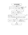
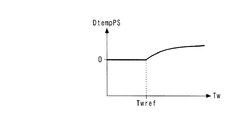
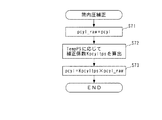
図14は、以上のようにして求めたセンサ温度TempPSの補正処理を示す。本処理は、センサ温度TempPSが実際には緩やかに変化することから、1燃焼サイクルよりも長い所定時間(例えば100msec)ごとに実行される。本処理ではまず、第1〜第3実施形態のいずれかにおいて温度検知処理により検知されたセンサ温度TempPSを、直接検知値TempPS_rawとして設定する(ステップ61)。次いで、エンジン水温Twに応じ、図15のテーブルを検索することによって、補正項DtempPSを算出する(ステップ62)。このテーブルでは、補正項DtempPSは、エンジン水温Twが、前記所定温度Temprefに相当する所定温度Twref(例えば25℃)未満のときには、値0に、すなわち実質的な温度補正がなされないように設定され、所定温度Twref以上のときには、値0よりも大きく、かつTw値が大きいほどより大きな値に設定されている。 FIG. 14 shows a correction process for the sensor temperature TempPS obtained as described above. This process is executed every predetermined time (for example, 100 msec) longer than one combustion cycle because the sensor temperature TempPS actually changes gradually. In this process, first, the sensor temperature TempPS detected by the temperature detection process in any of the first to third embodiments is directly set as a detected value TempPS_raw (step 61). Next, the correction term DtempPS is calculated by searching the table of FIG. 15 according to the engine coolant temperature Tw (step 62). In this table, the correction term DtempPS is set to a value of 0 when the engine water temperature Tw is lower than a predetermined temperature Twref (for example, 25 ° C.) corresponding to the predetermined temperature Tempref, that is, no substantial temperature correction is performed. When the temperature is equal to or higher than the predetermined temperature Twref, the value is set to a larger value as the value is larger than 0 and the Tw value is larger.
次に、直接検知値TempPS_rawに補正項DtempPSを加算した値を、補正されたセンサ温度TempPSとして算出し(ステップ63)、本処理を終了する。以上のように、この温度補正処理によれば、第1〜第3実施形態のいずれかにおいて図3の温度検知処理により検知されたセンサ温度TempPSを、検出された実際のエンジン水温Twに応じて補正する。したがって、エンジン3の始動時などに生じやすい実際の温度とのずれを解消でき、センサ温度TempPSの検知精度をさらに向上させることができる。
Next, a value obtained by adding the correction term DtempPS to the direct detection value TempPS_raw is calculated as the corrected sensor temperature TempPS (step 63), and this process is terminated. As described above, according to this temperature correction process, the sensor temperature TempPS detected by the temperature detection process of FIG. 3 in any one of the first to third embodiments is determined according to the detected actual engine water temperature Tw. to correct. Therefore, the deviation from the actual temperature that is likely to occur when the
なお、上述した例では、補正項DtempPSを直接検知値TempPS_rawに加算される加算項として求めているが、これに代えて、乗算項として求めてもよい。また、エンジン3の運転状態を表すパラメータとして、エンジン水温センサ23で検出されたエンジン水温Twを用いているが、これに代えて、他の適当なパラメータを用いてもよく、例えば吸気温センサ24で検出された吸気温Taを用いてもよい。
In the above-described example, the correction term DtempPS is obtained as an addition term that is directly added to the detected value TempPS_raw. However, instead of this, it may be obtained as a multiplication term. Further, although the engine water temperature Tw detected by the engine
図16は、センサ温度TempPSを用いた筒内圧pcylの補正処理を示す。この補正処理は、主として、ドリフトのリセットや補正を行わない第1実施形態で検知される筒内圧pcylに適用される。本処理ではまず、筒内圧センサ4の検出信号を積分することによって得られた筒内圧pcylを、直接筒内圧pcyl_rawとして設定する(ステップ71)。次いで、そのときのセンサ温度TempPSに応じ、図17のテーブルを検索することによって、補正係数Kpcyltpsを算出する(ステップ72)。このテーブルでは、補正係数Kpcyltpsは、センサ温度TempPSが、前記所定温度Tempref未満のときには、値1.0に、すなわち実質的な補正がなされないように設定され、所定温度Tempref以上のときには、値1.0よりも小さく、かつTempPS値が大きいほどより小さな値に設定されている。これは、温度が高いほどドリフト量が大きいという筒内圧センサ4のドリフト特性に基づくものである。
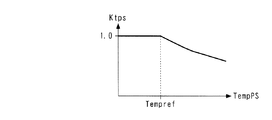
FIG. 16 shows a correction process for the in-cylinder pressure pcyl using the sensor temperature TempPS. This correction process is mainly applied to the in-cylinder pressure pcyl detected in the first embodiment in which the drift is not reset or corrected. In this process, first, the cylinder pressure pcyl obtained by integrating the detection signal of the
次に、直接筒内圧pcyl_rawに補正係数Kpcyltpsを乗算した値を、補正された筒内圧pcylとして算出し(ステップ73)、本処理を終了する。以上のように、この筒内圧補正処理によれば、例えば第1実施形態において筒内圧センサ4の検出結果に基づいて得られた筒内圧pcylを、検知されたセンサ温度TempPSに応じて補正するので、筒内圧センサ4の検出値を適切に温度補償することによって、温度によるドリフトの影響を排除でき、したがって、筒内圧pcylの検出精度を高めることができる。なお、この例では、補正係数Kpcyltpsを直接筒内圧pcyl_rawに乗算される乗算項として求めているが、加算項として求めてもよい。
Next, a value obtained by multiplying the direct in-cylinder pressure pcyl_raw by the correction coefficient Kpcyltps is calculated as the corrected in-cylinder pressure pcyl (step 73), and this process is terminated. As described above, according to the in-cylinder pressure correction process, for example, the in-cylinder pressure pcyl obtained based on the detection result of the in-
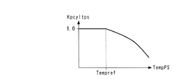
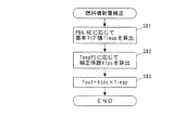
図18は、センサ温度TempPSを用いた燃料噴射量Toutの補正処理を示す。本処理は、TDC信号の発生に同期して実行される。本処理ではまず、吸気管内絶対圧PBAおよびエンジン回転数NEに応じ、燃料噴射量マップ(図示せず)を検索することによって、燃料噴射量の基本マップ値Timapを算出する(ステップ81)。次に、そのときのセンサ温度TempPSに応じ、図19のテーブルを検索することによって、補正係数Ktpsを算出する(ステップ82)。このテーブルでは、補正係数Ktpsは、センサ温度TempPSが、所定温度Tempref未満のときには、値1.0に、すなわち実質的な補正がなされないように設定され、所定温度Tempref以上のときには、値1.0よりも小さく、かつTempPS値が大きいほどより小さな値に設定されている。これは、センサ温度TempPSが高いほど、燃焼室3d内の温度が高いことで、燃焼室3dに供給される吸入空気の密度が小さく、実質的な吸入空気量が減少するので、それに応じて燃料噴射量Toutを減少させるためである。
FIG. 18 shows a process for correcting the fuel injection amount Tout using the sensor temperature TempPS. This process is executed in synchronization with the generation of the TDC signal. In this process, first, a basic map value Timmap of the fuel injection amount is calculated by searching a fuel injection amount map (not shown) according to the intake pipe absolute pressure PBA and the engine speed NE (step 81). Next, the correction coefficient Ktps is calculated by searching the table of FIG. 19 according to the sensor temperature TempPS at that time (step 82). In this table, the correction coefficient Ktps is set to a value of 1.0 when the sensor temperature TempPS is lower than the predetermined temperature Tempref, that is, so that no substantial correction is made, and when the sensor temperature Tempps is equal to or higher than the predetermined temperature Tempref. The smaller the value is, the smaller the TempPS value is. This is because, as the sensor temperature TempPS is higher, the temperature in the
次いで、基本マップ値Timapに補正係数Ktpsを乗算した値を、補正された燃料噴射量Toutとして算出し(ステップ83)、本処理を終了する。以上のように、この燃料噴射量補正処理によれば、基本マップ値Timapをセンサ温度TempPSに応じて補正する。筒内圧センサ4は燃焼室3dに近い部位に配置されるため、センサ温度TempPSはエンジン水温Twなどよりも燃焼室3dの温度を良好に表す。したがって、センサ温度TempPSによる燃料噴射量Toutの補正によって、吸入空気の密度を良好に反映させながら、燃料噴射量Toutやそれに基づく空燃比の制御などを適切に行うことができる。この場合、センサ温度TempPSが気筒3aごとに検知されるので、それに応じた燃料噴射量Toutの補正も気筒3aごとに行うことが可能であり、それにより、燃料噴射量Toutの制御をよりきめ細かく適切に行うことができる。なお、この例では、補正係数Ktpsを基本マップ値Timapに乗算される乗算項として求めているが、加算項として求めてもよい。
Next, a value obtained by multiplying the basic map value Timap by the correction coefficient Ktps is calculated as the corrected fuel injection amount Tout (step 83), and this process is terminated. As described above, according to the fuel injection amount correction process, the basic map value Timemap is corrected according to the sensor temperature TempPS. Since the in-
なお、本発明は、説明した実施形態に限定されることなく、種々の態様で実施することができる。例えば、実施形態では、ドリフト量driftに基づく統計処理値driftaveの逐次統計処理を、重み付き最小2乗法によって行っているが、本発明はこれに限らず、他の適当な演算手法によって行ってもよい。また、実施形態では、センサ温度TempPSで補正するエンジン3の制御入力として、燃料噴射量Toutを例示したが、これに代えて、あるいはこれとともに、他の制御入力、例えば点火時期IgtやEGR量などを補正してもよい。それにより、これらの制御入力を、燃焼室3d内の温度や吸入空気の温度などに応じて適切に設定でき、エンジン3の制御をより適切に行うことができる。
In addition, this invention can be implemented in various aspects, without being limited to the described embodiment. For example, in the embodiment, the sequential statistical processing of the statistical processing value driftave based on the drift amount drift is performed by the weighted least square method, but the present invention is not limited to this, and may be performed by other appropriate calculation methods. Good. In the embodiment, the fuel injection amount Tout is exemplified as the control input of the
また、本発明は、クランクシャフトを鉛直方向に配置した船外機などのような船舶推進機用エンジンを含む、様々な産業用の筒内噴射式の内燃機関の制御装置に適用することが可能である。その他、本発明の趣旨の範囲内で、細部の構成を適宜、変更することが可能である。 Further, the present invention can be applied to various industrial cylinder injection type internal combustion engine control devices including an engine for a marine propulsion device such as an outboard motor having a crankshaft arranged in a vertical direction. It is. In addition, it is possible to appropriately change the detailed configuration within the scope of the gist of the present invention.
2 ECU(ドリフトパラメータ演算手段、温度検知手段、温度補正手段、筒内圧補 正手段、制御入力設定手段、制御入力補正手段)
2b リセット回路(リセット手段)
2c ドリフト補正回路(ドリフト補正量設定手段)
3 エンジン
3a 気筒
4 筒内圧センサ
23 エンジン水温センサ(運転状態検出手段)
pcyl 筒内圧
drift ドリフト量
driftave ドリフト量の統計処理値(ドリフトパラメータ)
TempPS 筒内圧センサの温度
pcylpre リセット前筒内圧
pcylpost リセット後筒内圧
Δpcyl 筒内圧変化量
pcyl_comp ドリフト補正量
Tout 燃料噴射量(制御入力)
2 ECU (Drift parameter calculation means, temperature detection means, temperature correction means, in-cylinder pressure correction means, control input setting means, control input correction means)
2b Reset circuit (reset means)
2c Drift correction circuit (Drift correction amount setting means)
3
pcyl In-cylinder pressure drift drift amount driftave Statistical processing value of drift amount (drift parameter)
TempPS In-cylinder pressure sensor temperature pcylpre In-cylinder pressure before resetting pcylpost In-cylinder pressure after resetting Δpcyl In-cylinder pressure change amount pcyl_comp Drift correction amount
Tout Fuel injection amount (control input)
Claims (7)
前記筒内圧センサのドリフトを表すドリフトパラメータを演算するドリフトパラメータ演算手段と、
当該演算されたドリフトパラメータに基づいて、前記筒内圧センサの温度を検知する温度検知手段と、
を備えることを特徴とする筒内圧センサの温度検知装置。 A temperature detection device for an in-cylinder pressure sensor for detecting the temperature of an in-cylinder pressure sensor for detecting an in-cylinder pressure of an internal combustion engine,
Drift parameter calculating means for calculating a drift parameter representing drift of the in-cylinder pressure sensor;
Based on the calculated drift parameter, temperature detecting means for detecting the temperature of the in-cylinder pressure sensor;
A temperature detecting device for an in-cylinder pressure sensor.
前記ドリフトパラメータ演算手段は、前記リセット手段によるリセットの前後において検出された筒内圧に基づいて、前記ドリフトパラメータを演算することを特徴とする、請求項1または2に記載の筒内圧センサの温度検知装置。 A reset means for resetting drift of the in-cylinder pressure sensor;
The temperature detection of the in-cylinder pressure sensor according to claim 1 or 2, wherein the drift parameter calculation means calculates the drift parameter based on in-cylinder pressure detected before and after the reset by the reset means. apparatus.
前記ドリフトパラメータ演算手段は、前記ドリフト補正量設定手段で設定されたドリフト補正量に基づいて、前記ドリフトパラメータを演算することを特徴とする、請求項1または2に記載の筒内圧センサの温度検知装置。 A drift correction amount setting means for setting a drift correction amount for correcting drift of the in-cylinder pressure sensor;
3. The temperature detection of the in-cylinder pressure sensor according to claim 1, wherein the drift parameter calculation unit calculates the drift parameter based on a drift correction amount set by the drift correction amount setting unit. apparatus.
当該検出された内燃機関の運転状態に応じて、前記温度検知手段で検知された前記筒内圧センサの温度を補正する温度補正手段と、
をさらに備えることを特徴とする、請求項1ないし4のいずれかに記載の筒内圧センサの温度検知装置。 An operating state detecting means for detecting an operating state of the internal combustion engine;
Temperature correction means for correcting the temperature of the in-cylinder pressure sensor detected by the temperature detection means in accordance with the detected operating state of the internal combustion engine;
The temperature detecting device for an in-cylinder pressure sensor according to any one of claims 1 to 4, further comprising:
請求項1ないし5のいずれかに記載の筒内圧センサの温度検知装置によって検知された筒内圧センサの温度に応じて、前記設定された制御入力を補正する制御入力補正手段と、
を備えることを特徴とする内燃機関の制御装置。 Control input setting means for setting a control input for controlling the internal combustion engine;
Control input correction means for correcting the set control input according to the temperature of the in-cylinder pressure sensor detected by the in-cylinder pressure sensor temperature detection device according to any one of claims 1 to 5.
A control device for an internal combustion engine, comprising:
Priority Applications (1)
| Application Number | Priority Date | Filing Date | Title |
|---|---|---|---|
| JP2004109769A JP4340577B2 (en) | 2004-04-02 | 2004-04-02 | In-cylinder pressure sensor temperature detection device, in-cylinder pressure detection device using the same, and control device for internal combustion engine |
Applications Claiming Priority (1)
| Application Number | Priority Date | Filing Date | Title |
|---|---|---|---|
| JP2004109769A JP4340577B2 (en) | 2004-04-02 | 2004-04-02 | In-cylinder pressure sensor temperature detection device, in-cylinder pressure detection device using the same, and control device for internal combustion engine |
Publications (2)
| Publication Number | Publication Date |
|---|---|
| JP2005291146A true JP2005291146A (en) | 2005-10-20 |
| JP4340577B2 JP4340577B2 (en) | 2009-10-07 |
Family
ID=35324351
Family Applications (1)
| Application Number | Title | Priority Date | Filing Date |
|---|---|---|---|
| JP2004109769A Expired - Fee Related JP4340577B2 (en) | 2004-04-02 | 2004-04-02 | In-cylinder pressure sensor temperature detection device, in-cylinder pressure detection device using the same, and control device for internal combustion engine |
Country Status (1)
| Country | Link |
|---|---|
| JP (1) | JP4340577B2 (en) |
Cited By (2)
| Publication number | Priority date | Publication date | Assignee | Title |
|---|---|---|---|---|
| WO2011101984A1 (en) | 2010-02-16 | 2011-08-25 | トヨタ自動車株式会社 | In-cylinder pressure estimation device for internal combustion engine |
| JP2017032492A (en) * | 2015-08-05 | 2017-02-09 | トヨタ自動車株式会社 | Internal combustion engine control device |
Families Citing this family (1)
| Publication number | Priority date | Publication date | Assignee | Title |
|---|---|---|---|---|
| JP2019157696A (en) * | 2018-03-09 | 2019-09-19 | 本田技研工業株式会社 | Control device for internal combustion engine |
-
2004
- 2004-04-02 JP JP2004109769A patent/JP4340577B2/en not_active Expired - Fee Related
Cited By (4)
| Publication number | Priority date | Publication date | Assignee | Title |
|---|---|---|---|---|
| WO2011101984A1 (en) | 2010-02-16 | 2011-08-25 | トヨタ自動車株式会社 | In-cylinder pressure estimation device for internal combustion engine |
| US8495909B2 (en) | 2010-02-16 | 2013-07-30 | Toyota Jidosha Kabushiki Kaisha | Cylinder pressure estimation device of internal combustion engine |
| JP2017032492A (en) * | 2015-08-05 | 2017-02-09 | トヨタ自動車株式会社 | Internal combustion engine control device |
| CN106438038A (en) * | 2015-08-05 | 2017-02-22 | 丰田自动车株式会社 | Controller for internal combustion engine |
Also Published As
| Publication number | Publication date |
|---|---|
| JP4340577B2 (en) | 2009-10-07 |
Similar Documents
| Publication | Publication Date | Title |
|---|---|---|
| JP4130800B2 (en) | Engine control device | |
| EP2284378A2 (en) | Engine control apparatus | |
| JP2009007966A (en) | Control device for internal combustion engine | |
| US7971571B2 (en) | Operation control method on the basis of ion current in internal combustion engine | |
| JP2015197083A (en) | Internal combustion engine cylinder internal pressure detector | |
| JP6006228B2 (en) | In-cylinder pressure sensor abnormality diagnosis device and in-cylinder pressure sensor sensitivity correction device including the same | |
| JP2007278223A (en) | Control device for cylinder-injection spark-ignition internal combustion engine | |
| JP2005330856A (en) | Control device for automobile | |
| JP2009008005A (en) | Control device for internal combustion engine | |
| JP2008180225A (en) | Engine control device | |
| JP4340577B2 (en) | In-cylinder pressure sensor temperature detection device, in-cylinder pressure detection device using the same, and control device for internal combustion engine | |
| JP2007154802A (en) | Control device of internal combustion engine | |
| JP2007309309A (en) | Control device for internal combustion engine | |
| JP4792453B2 (en) | Intake air amount detection device | |
| JP2002097996A (en) | Combustion state detecting device of internal combustion engine | |
| JP2008202461A (en) | Fuel injection control device for internal combustion engine | |
| JP2010203311A (en) | Control device for internal combustion engine | |
| JP2007303352A (en) | Misfire determination device for internal combustion engine | |
| JP2008180174A (en) | Control device for internal combustion engine | |
| JP2017020417A (en) | Control device of internal combustion engine | |
| JP4115677B2 (en) | Atmospheric pressure detection device for internal combustion engine | |
| JP2006071334A (en) | Temperature detection apparatus for vehicle | |
| JP4491739B2 (en) | Control device for internal combustion engine | |
| JP2007077856A (en) | Combustion condition judgment device for internal combustion engine | |
| JP4304669B2 (en) | Crank angle discrimination device for internal combustion engine |
Legal Events
| Date | Code | Title | Description |
|---|---|---|---|
| A621 | Written request for application examination |
Free format text: JAPANESE INTERMEDIATE CODE: A621 Effective date: 20061128 |
|
| A977 | Report on retrieval |
Free format text: JAPANESE INTERMEDIATE CODE: A971007 Effective date: 20081020 |
|
| A131 | Notification of reasons for refusal |
Free format text: JAPANESE INTERMEDIATE CODE: A131 Effective date: 20081028 |
|
| A521 | Written amendment |
Free format text: JAPANESE INTERMEDIATE CODE: A523 Effective date: 20081226 |
|
| A131 | Notification of reasons for refusal |
Free format text: JAPANESE INTERMEDIATE CODE: A131 Effective date: 20090414 |
|
| A521 | Written amendment |
Free format text: JAPANESE INTERMEDIATE CODE: A523 Effective date: 20090513 |
|
| TRDD | Decision of grant or rejection written | ||
| A01 | Written decision to grant a patent or to grant a registration (utility model) |
Free format text: JAPANESE INTERMEDIATE CODE: A01 Effective date: 20090609 |
|
| A01 | Written decision to grant a patent or to grant a registration (utility model) |
Free format text: JAPANESE INTERMEDIATE CODE: A01 |
|
| A61 | First payment of annual fees (during grant procedure) |
Free format text: JAPANESE INTERMEDIATE CODE: A61 Effective date: 20090706 |
|
| R150 | Certificate of patent or registration of utility model |
Ref document number: 4340577 Country of ref document: JP Free format text: JAPANESE INTERMEDIATE CODE: R150 Free format text: JAPANESE INTERMEDIATE CODE: R150 |
|
| FPAY | Renewal fee payment (event date is renewal date of database) |
Free format text: PAYMENT UNTIL: 20120710 Year of fee payment: 3 |
|
| FPAY | Renewal fee payment (event date is renewal date of database) |
Free format text: PAYMENT UNTIL: 20120710 Year of fee payment: 3 |
|
| FPAY | Renewal fee payment (event date is renewal date of database) |
Free format text: PAYMENT UNTIL: 20130710 Year of fee payment: 4 |
|
| FPAY | Renewal fee payment (event date is renewal date of database) |
Free format text: PAYMENT UNTIL: 20140710 Year of fee payment: 5 |
|
| R250 | Receipt of annual fees |
Free format text: JAPANESE INTERMEDIATE CODE: R250 |
|
| LAPS | Cancellation because of no payment of annual fees |