JP2005290833A - Intrusive body feed device to sub-grade etc - Google Patents
Intrusive body feed device to sub-grade etc Download PDFInfo
- Publication number
- JP2005290833A JP2005290833A JP2004107169A JP2004107169A JP2005290833A JP 2005290833 A JP2005290833 A JP 2005290833A JP 2004107169 A JP2004107169 A JP 2004107169A JP 2004107169 A JP2004107169 A JP 2004107169A JP 2005290833 A JP2005290833 A JP 2005290833A
- Authority
- JP
- Japan
- Prior art keywords
- vibration
- ground
- penetration
- feeding device
- feed device
- Prior art date
- Legal status (The legal status is an assumption and is not a legal conclusion. Google has not performed a legal analysis and makes no representation as to the accuracy of the status listed.)
- Withdrawn
Links
Images

Abstract
Description
本発明は、ガイドセルに沿って前後進自在に搭載され、保持した穿孔ロッド、杭などの貫入体を地盤、コンクリート、道路路盤等に貫入させるための送り装置に係り、詳しくは推進力と共に、回転力と振動を与えながら貫入体を地盤等へ貫入させる、所謂ロータリーバイブレーション方式の送り装置に関する。 The present invention relates to a feed device that is mounted so as to freely move back and forth along a guide cell, and allows a penetrating rod, a pile, and the like to penetrate into the ground, concrete, road base, etc. The present invention relates to a so-called rotary vibration type feeding device that allows a penetrating body to penetrate into the ground or the like while applying rotational force and vibration.
地盤改良工事、トンネル掘削における装薬孔、アンカー設置工事、基礎杭の造成工事等の土木工事においては、地盤中に薬液注入孔や、アンカー設置孔などの穿孔を形成するため、或いは杭を地盤中に打設する等のために、穿孔機又は杭打ち機等が用いられる。この穿孔機又は杭打ち機は、基本的には、ガイドセル上に前後進自在にドリフターと呼ばれる送り装置を搭載し、この送り装置の前面側にシャンクロッドや接続アダプターなどの連結材を介して穿孔ロッドや杭体を保持し、前記送り装置による前進による推進力と共に回転力を与え、更には削孔効率を上げるために、打撃を与えたり、振動を与えたりしながら、前記地盤貫入体を地盤に挿入している。前者の回転と共に打撃を与える方式はロータリーパーカッションと呼ばれる方式であり、後者の回転と共に振動を与える方式はロータリーバイブレーションと呼ばれる方式である。 In civil engineering work such as ground improvement work, charge holes in tunnel excavation, anchor installation work, foundation pile construction work, etc., to form drill holes such as chemical injection holes and anchor installation holes in the ground, or piles in the ground A drilling machine or a pile driving machine or the like is used for placing the inside. This drilling machine or pile driving machine basically has a feeding device called a drifter mounted on a guide cell so as to be able to move forward and backward, and via a connecting material such as a shank rod or a connection adapter on the front side of the feeding device. Holding the drilling rod and pile body, giving a rotational force along with the propulsion force by the advance by the feeding device, and further increasing the drilling efficiency, giving the striking intrusion body while giving impact and vibration. Inserted into the ground. The method of giving an impact with the former rotation is a method called rotary percussion, and the method of giving vibration with the latter rotation is a method called rotary vibration.
前記ロータリーパーカッション方式は、回転により摩擦低減を図りながら、打撃により硬質土層を破壊することで地盤反力の低減を図れる利点があり、貫入効率が高いため、従来より多用されているが、騒音が大きく、特に住宅地や市街地若しくはその隣接地域では採用し得ないなどの問題があった。 The rotary percussion method has the advantage that the ground reaction force can be reduced by destroying the hard soil layer by striking while reducing friction by rotation, and the penetration efficiency is high. In particular, there were problems such as being unable to employ in residential areas, urban areas, or adjacent areas.
一方、前記ロータリーバイブレーション方式は、送り装置の内部に起振装置を備え、地盤貫入体に回転と共に振動を与えるものであり、低騒音化が可能である、回転のみの場合よりも高い穿孔効率が得られるなどの利点から近年、採用され始めている方式である。 On the other hand, the above-mentioned rotary vibration system is provided with a vibration generator inside the feeding device and gives vibration to the ground penetrating body together with rotation, which can reduce noise and has a higher drilling efficiency than that of rotation alone. In recent years, this method has begun to be adopted because of its advantages.
前記ロータリーバイブレーション方式による先行文献としては、例えば下記特許文献1〜3を挙げることができる。下記特許文献1では、ロッドを軸方向に振動させるために、フレームに軸線方向に偏倚自在に設けられたロータハウジングと、このロータハウジング内に収容され、所定の周波数で回転して起振力を発生させる複数枚の偏心ロータと、前記ロッドの後端を前記ロータハウジングに回転自在に連結するための連結手段とからなる振動発生装置が開示されている。また、下記特許文献2では、1台の電動機と、その電動機を中心として対称に同軸に配置される2体の偏心ロータとから構成された振動モータを用いた加振機を取り付けた杭打ち機が開示されている。さらに、下記特許文献3では、一対の偏心ロータを備えた振動モータを起振装置を備える送り装置において、前記振動モータの外側に振動を吸収する防振体を設けることにより騒音の低減を図った地盤穿孔装置が開示されている。
前記ロータリーバイブレーション方式は、ロータリーパーカッション方式と比べると、小さな振幅の振動を加えることで、すなわち小さな打撃力を小刻みに加えることにより、ハンマーを無くし低騒音化を実現するものであるが、実際に市場に提供されている穿孔機及び杭打ち機の性能を比較してみると、上記特許文献1〜3に記載されるような、偏心ロータの回転による振動を発生させる起振装置の場合の振動数は、概ね500〜3600cpm程度であり、一方前記ロータリーパーカッションによる打撃回数も2000〜3500bpmであり、両者には有意差は無く、ロータリーバイブレーション方式は、推進力と共に回転力のみを与えるロータリー方式に比べると穿孔効率又は杭貫入効率は高いが、ロータリーパーカッション方式に比べると、打撃力が弱い分、どうしても穿孔効率又は杭貫入効率が劣るという問題があり、ロータリーバイブレーションの利点を最大限に生かすには、現状の振動数では不十分で、より高い振動数の振動を与えることができる起振装置が強く望まれている。
Compared with the rotary percussion method, the rotary vibration method is designed to reduce the noise by adding a small amplitude of vibration, that is, by adding a small striking force in small increments. When comparing the performance of the drilling machine and the pile driving machine provided in the above, the frequency in the case of a vibration generating device that generates vibration due to the rotation of the eccentric rotor as described in
また、前記ロータリーバイブレーション方式では、穿孔効率又は杭貫入効率を高めるため、振幅を大きくして、より大きな衝撃力を作るようにしているが、ビットに掛かる負担が大きくなるため、硬岩ではビットが破損する場合があった。この点を改良するには、より小さな振幅で高い振動数の振動を与えるようにすればよいことになるが、従来の偏心ロータによる起振装置では、モータを駆動源としているため、機構的に振動数に限界があった。 In the rotary vibration method, in order to increase the drilling efficiency or the pile penetration efficiency, the amplitude is increased to create a larger impact force. However, since the burden on the bit is increased, the bit is not formed on the hard rock. There was a case where it was damaged. In order to improve this point, it is only necessary to give a vibration with a smaller amplitude and a higher frequency. However, in the conventional vibration generator using an eccentric rotor, the motor is used as the drive source, and thus mechanically. There was a limit to the frequency.
また、偏心ロータを回転させる従来の起振装置の場合には、機械的駆動であるため、軸受けのベアリングが破損するなどの問題があるとともに、寸法及び重量が嵩むようになる、さらには振動が起振装置を介して穿孔機又は杭打ち機全体に伝わる、特に斜め掘りの場合には、重力との合成で穿孔機全体が振動し易いなどの問題があった。 Further, in the case of the conventional vibration generator that rotates the eccentric rotor, since it is mechanically driven, there are problems such as damage to the bearings of the bearing, and the size and weight increase, and further vibration occurs. In the case of oblique digging, which is transmitted to the entire drilling machine or pile driving machine through the vibration device, there is a problem that the entire drilling machine easily vibrates due to the combination with gravity.
さらに、より低騒音化を図るには、上記特許文献2のように起振部の周囲に防振体を介在させる方法が提案されているけれども、振動による騒音を極小にすることはできず、かつ送り装置の構造も複雑化するなどの問題があった。
Furthermore, in order to further reduce noise, a method of interposing a vibration isolator around the vibration generating portion as in
一方、前記ロータリーバイブレーション方式の起振装置の起振力は、振動体の自重、振幅、振動数の二乗に比例する関係にある。偏心ロータを回転させる従来の起振装置は、偏心ロータが振動体の自重に含まれる。そのため、起振力を大きくするために偏心ロータを大きくすると自重が増えることになり、両者の関係がイタチごっことなり、振動数に制限を受けるなどの問題があった。 On the other hand, the vibratory force of the rotary vibration type vibrator is proportional to the weight of the vibrating body, the amplitude, and the square of the vibration frequency. In the conventional vibration generating device that rotates the eccentric rotor, the eccentric rotor is included in the dead weight of the vibrating body. For this reason, if the eccentric rotor is increased in order to increase the vibration generating force, the weight of the rotor increases, and the relationship between the two becomes itachi and the frequency is limited.
他方、環境関連での土のサンプリングにおいては、穿孔ロッドの打撃ではサンプリング地盤を破壊する、発熱により変質するという問題があり、ロータリーバイブレーション方式はロータリーパーカッション方式と比べると、打撃力が弱くてもサンプリング地盤の破壊低減、発熱の低減の利点はある。しかし、更に打撃力を小さくても、振動数を多くし加速度を大きくすることにより、サンプリング地盤の破壊低減、発熱の低減を図りながら、効率的な削孔を実現可能とする方法が求められている。 On the other hand, in soil sampling related to the environment, there is a problem that the drilling of the perforated rod destroys the sampling ground and changes quality due to heat generation, and the rotary vibration method is sampled even if the impact force is weak compared to the rotary percussion method. There are advantages of ground destruction reduction and heat generation reduction. However, there is a need for a method that enables efficient drilling while reducing the sampling ground destruction and heat generation by increasing the frequency and increasing the acceleration even if the impact force is further reduced. Yes.
そこで、本発明の主たる課題は、小さな振幅で高い振動数の振動を生起可能とし、穿孔効率及び杭貫入効率等の効率化を図るとともに、ビットへの負担を小さくし長寿命化を図ることにある。また、軸受け部分の破損等、振動生起による機器の破損を無くすことが可能であるとともに、振動による騒音発生を実質的に極小とし、更に装置のコンパクト化及び軽量化が図れるようにするなど、前述した偏心ロータを用いた起振装置の問題点を一掃するとともに、更に地盤の破壊、変質させることなく地盤のサンプリングを効率的に行い得る地盤等への貫入体送り装置を提供することにある。 Therefore, the main problem of the present invention is to make it possible to generate vibration at a high frequency with a small amplitude, to improve efficiency such as drilling efficiency and pile penetration efficiency, and to reduce the burden on the bit and extend the life. is there. In addition, it is possible to eliminate damage to the equipment due to vibration such as damage to the bearing part, to substantially minimize noise generation due to vibration, and to further reduce the size and weight of the device. An object of the present invention is to provide a penetrating body feeding device to the ground or the like that can efficiently sample the ground without destroying or altering the ground, while eliminating the problems of the vibration generating device using the eccentric rotor.
前記課題を解決するために請求項1に係る本発明として、ガイドセルに沿って前後進自在に搭載され、保持した貫入体に推進力と共に、回転力と振動を与えながら、地盤等に貫入させるための送り装置であって、
前記送り装置における起振手段として、リニアモータ方式を採用し、前記送り装置内において前記貫入体と中間部材を介して連結されている加振用駆動体を軸線方向に微小幅で往復移動させて振動を生起するようにしたことを特徴とする地盤等への貫入体送り装置が提供される。
In order to solve the above-mentioned problem, the present invention according to
As the vibration generating means in the feeding device, a linear motor system is adopted, and the excitation driving body connected to the penetrating body and the intermediate member in the feeding device is reciprocated with a minute width in the axial direction. There is provided a penetrating body feeding device to the ground or the like, characterized by causing vibration.
上記請求項1記載の本発明においては、起振手段として、リニアモータ方式を採用し、前記送り装置内において加振用駆動体を軸線方向に微小幅で往復移動させて振動を生起するようにした。 In the first aspect of the present invention, a linear motor system is employed as the vibration generating means, and vibration is generated by reciprocating the vibration driver in the axial direction with a minute width in the feeder. did.
起振手段として、リニアモータ方式を採用することにより、振幅や振動数に制限がなくなり、任意に設定することができるようになる。貫入体に小さな振幅で高い振動数の振動を与えることにより、穿孔効率及び貫入効率の効率化を図るとともに、ビットへの負担を小さくし長寿命化を図ることが可能となる。 By adopting a linear motor system as the vibration generating means, there are no restrictions on the amplitude and frequency, and it can be set arbitrarily. By giving a high frequency vibration with a small amplitude to the penetrating body, it is possible to improve the drilling efficiency and the penetration efficiency, reduce the burden on the bit, and extend the life.
また、往復運動を行う加振用駆動体は、周囲と非接触であるため、軸受け部分の破損等、振動生起による機器の破損を無くすことが可能であるとともに、振動による騒音発生を実質的に極小とできるようになる。 In addition, since the vibration driver that reciprocates is not in contact with the surroundings, it is possible to eliminate damage to the equipment due to vibration, such as damage to the bearings, and substantially reduce noise generation due to vibration. You can do it with a minimum.
さらに、構造が単純化できるため、装置のコンパクト化及び軽量化が図れるようになるなど、従来の偏心ロータを用いた起振装置の問題点を一掃できるようになる。また、更には地盤の破壊、変質させることなく地盤のサンプリングを効率的に行い得るようになる。 Furthermore, since the structure can be simplified, the problems of the conventional vibration generating device using the eccentric rotor can be eliminated, such as reduction in the size and weight of the device. Furthermore, the ground can be efficiently sampled without destroying or altering the ground.
請求項2に係る本発明として、前記貫入体に与える振動は、振幅が0を超え10mm以内、振動数が0を超え12000cpm以内とする請求項1記載の地盤等への貫入体送り装置が提供される。より具体的には、前記貫入体に与える振動は、振幅が0を超え10mm以内、好ましくは0.01〜3mm、振動数が0を超え12000cpm以内、好ましくは10〜10000cpmとするのが望ましい。 According to a second aspect of the present invention, there is provided the penetrating body feeding device to the ground or the like according to the first aspect, wherein the vibration applied to the penetrating body has an amplitude exceeding 0 and within 10 mm and a vibration frequency exceeding 0 and within 12000 cpm. Is done. More specifically, it is desirable that the vibration applied to the penetrating body has an amplitude exceeding 0 and within 10 mm, preferably 0.01 to 3 mm, and a frequency exceeding 0 and within 12000 cpm, preferably 10 to 10000 cpm.
請求項3に係る本発明として、前記貫入体が穿孔ロッド又は杭体である請求項1,2いずれかに記載の地盤等への貫入体送り装置が提供される。 According to a third aspect of the present invention, there is provided the penetrating body feeding device to the ground or the like according to any one of the first and second aspects, wherein the penetrating body is a perforated rod or a pile body.
請求項4に係る本発明として、前記加振用駆動体をバネ定数を可変とした弾発体によって支持した請求項1〜3いずれかに記載の地盤等への貫入体送り装置が提供される。 According to a fourth aspect of the present invention, there is provided the penetrating body feeding device to the ground or the like according to any one of the first to third aspects, wherein the excitation driving body is supported by an elastic body having a variable spring constant. .
起振力を大きくしたい場合には、推進力の大きなリニアモータを選定することになるが、リニアモータの推力は磁気の当たり面積(極板面積)に比例するため、過大なリニアモータが必要となってしまう。そこで、加振用駆動体を支持するためにバネ定数を可変とした弾発体を組み込み、バネ定数を共振する周波数(固有振動数)近傍に設定すると、起振力とバネ定数とが相殺されることになり、このバネによって起振補助力が生起され、前記加振用駆動体をコンパクトなリニアモータによって振動させ得るようになる。バネ定数を可変とする具体的方法としては、例えば板バネの加重作用点を移動させる方法、空気バネの空気圧を制御する方法などがある。 If you want to increase the excitation force, select a linear motor with a large propulsive force. However, since the thrust of the linear motor is proportional to the magnetic contact area (pole plate area), an excessively large linear motor is required. turn into. Therefore, if an elastic body with a variable spring constant is incorporated to support the drive body for excitation and the spring constant is set near the resonance frequency (natural frequency), the excitation force and the spring constant are canceled out. Thus, a vibration assisting force is generated by the spring, and the vibration driver can be vibrated by a compact linear motor. Specific methods for making the spring constant variable include, for example, a method of moving the load acting point of the leaf spring, a method of controlling the air pressure of the air spring, and the like.
なお、バネ定数が一定の場合には、種々の条件に対応して共振する周波数(固有振動数)近傍に設定することができないため好ましくない。 A constant spring constant is not preferable because it cannot be set in the vicinity of a frequency (natural frequency) that resonates in accordance with various conditions.
請求項5に係る本発明として、前記貫入体の貫入対象物が地盤、コンクリート、道路路盤などである請求項1〜4いずれかに記載の地盤等への貫入体送り装置が提供される。 According to a fifth aspect of the present invention, there is provided the penetrating body feeding device for a ground or the like according to any one of the first to fourth aspects, wherein the penetration object of the penetrating body is a ground, concrete, road roadbed or the like.
以上詳説のとおり本発明によれば、小さな振幅で高い振動数の振動を生起可能となるため、穿孔効率及び杭貫入効率の向上が図れるようになるとともに、ビットへの負担が小さくなるため長寿命化を図ることが可能となる。また、軸受け部分の破損等、振動生起による機器の破損を無くすことが可能であるとともに、振動による騒音発生を実質的に極小とできるようになる。更には、装置のコンパクト化及び軽量化が図れるなど、前述した偏心ロータを用いた起振装置の問題点を一掃できるようになる。また、地盤の破壊、変質させることなく地盤のサンプリングが可能となるなどの利点がもたらされるようになる。 As described above in detail, according to the present invention, vibration with a high frequency can be generated with a small amplitude, so that the drilling efficiency and the pile penetration efficiency can be improved, and the burden on the bit is reduced, resulting in a long service life. Can be achieved. In addition, it is possible to eliminate damage to the equipment due to vibration such as damage to the bearing portion, and to substantially minimize noise generation due to vibration. Furthermore, the problems of the vibration generator using the eccentric rotor described above, such as reduction in the size and weight of the apparatus, can be eliminated. In addition, there are advantages such as the ability to sample the ground without destroying or altering the ground.
以下、本発明の実施の形態について図面を参照しながら詳述する。
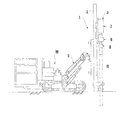
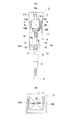
図1は本発明に係る穿孔機1を支持したクローラー式走行台車Mの側面図であり、図2はガイドセル2に搭載された送り装置3(ドリフター)を示す、(A)は正面側からの縦断面図、(B)は(A)のB−B線矢視図である。
Hereinafter, embodiments of the present invention will be described in detail with reference to the drawings.
FIG. 1 is a side view of a crawler type traveling carriage M that supports a
前記クローラー式走行台車Mは、クローラーにより走行自在とした重機であり、ガイドセル2をブーム5により支持している。前記ブーム5は、基端側において鉛直軸回りに回動自在、複数の油圧シリンダーによってガイドセル2を伏仰自在、そして先端部でガイドセル2を水平軸回りに回動自在に支持しており、図示例では前記ガイドセル2を地盤に向けて鉛直に保持している。当然に、斜め方向の穿孔、水平方向の穿孔も可能である。
The crawler type traveling carriage M is a heavy machine that can be freely traveled by a crawler, and the
前記ガイドセル2には、該ガイドセル2の部材方向に沿って前後進自在に送り装置3が搭載されている。前記送り装置3の推進手段としては、例えば駆動モーターによりスプロケットを介して駆動されるフィードチェーンによって走行する構造とされ、保持した穿孔ロッドRをガイドセル2に沿って前進又は後退させ、保持された穿孔ロッドRを地盤Gへ向けて貫入及び/又は地盤から引抜きできるようになっている。
A
前記送り装置3は、穿孔ロッドRを保持するとともに、前記穿孔ロッドRを軸方向に微小幅で往復移動させ、振動を生起するための振動発生装置7と、前記穿孔ロッドRを軸芯回りに回転させる回転駆動装置6とを含み、前記ロッドRに回転と共に、振動を与えながら穿孔ロッドRを地盤に貫入させる、所謂ロータリーバイブレーション方式の送り装置である。
The
前記回転駆動装置6は、図2に示されるように、回転部ハウジング11内に、内歯と外歯とを備えるリングギア12がベアリングを介して回転自在に収容されている。そして、主軸を構成するシャンクロッド9が、前記回転部ハウジング11内を貫通して設けられるとともに、中間のスプライン13が前記リングギア12の内歯に噛合するように配置され、前記スプライン13の形成範囲内で軸線方向に移動可能となっている。
As shown in FIG. 2, in the
また、前記回転部ハウジング11の上面には、複数の、図示例では左右両側に夫々駆動モーター14,14…が固定され、各出力軸14a、14a…を前記主軸ハウジング11内に臨ませ、前記出力軸14aの先端に設けられたピニオン15,15…がリングギア12の外歯と噛合するようになっており、前記シャンクロッド9が軸芯回りに回転駆動されるようになっている。
Further, a plurality of
前記回転駆動装置6の上部側に設けられた振動発生装置7は、振動部ハウジング17と、この振動部ハウジング17の内部に、穿孔ロッドRの軸方向に所定範囲で往復動可能に加振用駆動体16が設けられている。また、前記加振用駆動体16の上端には軸部16aが突出して設けられるとともに、振動ハウジング17側に前記軸部16aが貫入される受け筒17aが設けられ、前記加振用駆動体16の振動をガイドするようになっている。また、前記加振用駆動体16の下端には、連結部材18が回転自在に軸受けによって支持され、この連結部材18の下端に形成された雌ネジ孔18aに、前記シャンクロッド9の上端部が螺合接続されている。また、前記シャンクロッド9の先端側にはアダプター8が接続され、穿孔ロッドRが前記アダプター8を介して接続されるようになっている。
The
本送り装置3においては、前記振動発生装置7の起振手段として、リニアモータ方式が採用されている。
In this
前記振動部ハウジング17の内部側両側面には、長手方向に沿ってリニアモータ4、4が、図2(B)に示されるように、振動方向に沿って直線状に設けられている。このリニアモータ4が本発明に係る穿孔機1における振動発生源とされる。
As shown in FIG. 2B,
前記リニアモータ4は、振動用ハウジング16側に固定された二次側コア19Bと、前記加振用駆動体17に対して、前記二次側コア19Bに対向させるようにして振動部ハウジング17に固定された一次側コア19Aとから構成されている。
The
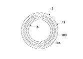
前記二次側コア19Bは、図6に示されるように、往復移動方向に沿って所定ピッチで凹部と凸部とが交互に並んだ歯部19d、19d…が形成された固定側に設けられる導体であり、前記一次側コア19Aは、一次側磁束発生部として往復動作する移動体側に設けられる部材(一次側コイル部材)である。
As shown in FIG. 6, the
従来より、前記リニアモータ4の構造について種々の構造が提供されている。例えば、図6に示されるリニアモータ4Aについて詳述すると、一次側コア19Aには、略中央部に大きな凹部19aが設けられており、この凹部19aを挟んで長手方向両部に夫々永久磁石20,20が設けられている。前記永久磁石20,20は、双方で同じ面側が同じ磁極とならないように配設されている。すなわち、図示の例では、左側の永久磁石20は、上面側にS極、下面側にN極が位置するように設けられ、右側の永久磁石20は、上面側にN極、下面側にS極が位置するように設けられている。前記永久磁石20,20が設けられた範囲内において、略中央部の二次側コア19Bとの対峙面側に凹部19b、19cが夫々設けられており、凹部19bを挟んで磁極Aおよび磁極A’が、凹部19cを挟んで磁極Bおよび磁極B’が夫々形成されている。さらに、前記磁極A,A’及び磁極B、B’にはそれぞれ鉛直軸回りにコイル21が巻回されている。
Conventionally, various structures have been provided for the structure of the
前記リニアモータ4Aにおいては、前記コイル21に所定の励磁力で極性が反転するパルス電流を流すと、図中矢印で示される磁束Φ1が得られて歯部19dと各磁極との間に発生する推力ベクトルが変化して一次側コア19Aが二次側コア19Bに沿って移動するようになっている。また、本発明に従って、加振用駆動体16を振動させるには、励磁シーケンスで前記パルス電流の方向を高速で交互に反転させるようにして、前記一次側コア19Aが固定された加振駆動体16を穿孔ロッドRの方向に往復移動させて振動を生起するようにする。
Wherein the
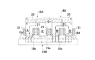
また、図7に示されるリニアモータ4Bは、前述したリニアモータ4Aと比べて倍の推力が得られるようにした公知のリニアモータである。特に、リニアモータを振動発生手段として用いる送り装置3の場合には、極力大きな推力が得られた方が望ましいため、図7に示されるリニアモータ構造とするのが望ましい。
Further, the
前記リニアモータ4Bは、一次側コア19Aの中央部に、溝深の浅い中央凹部19eが設けられており、この中央凹部19eを挟んで図中左側に磁極Aが、同右側に磁極A’が形成されており、各磁極にはコイル21,21…が巻回されている。また、前記各磁極には、二次側コア19Bとの対峙面側に一定間隔で空隙溝19f、19f…が形成されるとともに、この各空隙溝19fに永久磁石20が夫々埋め込まれている。この永久磁石20は、隣り合う磁石同士で対峙面が同じ磁極となるように配置されている。図示例では磁極A、磁極A’共に、左からN、S、S、N、N、Sの順序となるように永久磁石20が配置されている。なお、二次側コア19Bは、歯部19dの形状は大きいものの、基本的には構成は変わらない。
The
前記リニアモータ4Bの場合には、コイル21に電流を流すと、磁極Aにおいて図中左側方向(同図矢印方向)に一次側コイル19Aが移動するような磁束Φ2が得られるとともに、磁極A’側においても、図中左側方向(同図矢印方向)に一次側コイル19Aが移動するような磁束Φ2が得られるため、両極共に推力の発生に寄与できるので、より大きな推進力を得ることができるようになっている。
In the case of the
前記振動発生装置7により発生させる振動は、振幅が0を超え10mm以内、好ましくは0.01〜3mm、振動数が0を超え12000cpm以内、好ましくは10〜10000cpmとするのが望ましい。
The vibration generated by the
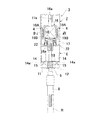
ところで、前記送り装置3においては、図3に示されるように、前記加振用駆動体16をバネ定数を可変とした弾発体22によって支持するようにするのが望ましい。図示の弾発体22は、ゴム中空体の内部へ空気などの流体を供給/引抜き制御することによりバネ定数を可変としたものである。他の例としては、例えば板バネの加重作用点を移動させる方法などを挙げることができる。前記加振用駆動体16を支持するためにバネ定数を可変とした弾発体22を組み込み、バネ定数を共振する周波数(固有振動数)近傍に設定すると、このバネ作用によって起振補助力が生起され、前記加振用駆動体16をコンパクトなリニアモータによって振動させ得るようになる。なお、前記弾発体22は、加振用振動体16の上部側に設けるようにしてもよいし、上下部両方に設けるようにしてもよい。
By the way, in the
前記穿孔機1により穿孔を行うには、シャンクロッド9に、回転駆動装置6より回転力が付与されるとともに、前記振動発生装置7より連結部材18及びシャンクロッド9を介して穿孔ロッドRに振動が付与され、穿孔ロッドRを効率的に地盤中に貫入させることができる。
In order to perform drilling by the
なお、上記説明では穿孔機の送り装置3として使用する場合について詳述したが、杭打ち機の場合にも、前記穿孔ロッドRに代えて杭体が送り装置3に対してチャック手段等を介して保持されるだけの相違であり、送り装置3としては同じ構造のものが使用されるため、振動発生装置7としてリニアモータを利用した本送り装置3をそのまま使用することが可能である。
In the above description, the case where the punching machine is used as the
〔他の形態例〕
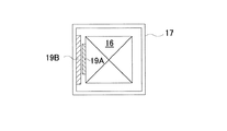
(1)上記例では、振動発生装置7において、加振駆動体16の両側部に夫々リニアモータ4、4を設けるようにしたが、前記リニアモータ4Aは、図4に示されるように、片側にのみ設けることとしてもよいし、4辺それぞれに設けるようにしてもよい(図示せず)。さらには、図5に示されるように、加振駆動体16の周方向に連続して環状に設けることとしてもよい。
(2)上記例では、穿孔機1を搭載する台車をクローラー式走行車Mとした場合について詳述したが、穿孔機1を支持する構造体は何でもよい。例えば、タイヤ式走行車、架台(ジャンボ)等であってもよい。
(3)本発明に係る振動発生装置7は、地盤貫入体のための送り装置3として利用した場合について詳述したが、前記振動発生装置7は単独で使用可能な起振装置とすることも可能である。用途として、例えば型枠外面に装着されコンクリートを締め固める際に用いる型枠振動機等、加振手段全般に適用することができる。
(4)上記形態例では、地盤を対象としているが、貫入対象はコンクリートや道路路盤等であってもよい。
[Other examples]
(1) In the above example, in the
(2) In the above example, the case where the cart on which the
(3) Although the
(4) In the above embodiment, the ground is targeted, but the penetration target may be concrete, roadbed, or the like.
1…穿孔機、2…ガイドセル、3…送り装置、4…リニアモータ、6…回転駆動装置、7…振動発生装置、8…アダプター、9…シャンクロッド、19A…一次側コア、19B…二次側コア
DESCRIPTION OF
Claims (5)
前記送り装置における起振手段として、リニアモータ方式を採用し、前記送り装置内において前記貫入体と中間部材を介して連結されている加振用駆動体を軸線方向に微小幅で往復移動させて振動を生起するようにしたことを特徴とする地盤等への貫入体送り装置。 A feed device that is mounted so as to be able to move forward and backward along the guide cell, and that penetrates the ground while giving rotational force and vibration along with propulsive force to the held penetration body,
As the vibration generating means in the feeding device, a linear motor system is adopted, and the excitation driving body connected to the penetrating body and the intermediate member in the feeding device is reciprocated with a minute width in the axial direction. A penetrating body feeding device to the ground or the like characterized by causing vibration.
The penetration body feeding apparatus to the ground etc. in any one of Claims 1-4 whose penetration object of the said penetration body is a ground, concrete, a road roadbed, etc.
Priority Applications (1)
| Application Number | Priority Date | Filing Date | Title |
|---|---|---|---|
| JP2004107169A JP2005290833A (en) | 2004-03-31 | 2004-03-31 | Intrusive body feed device to sub-grade etc |
Applications Claiming Priority (1)
| Application Number | Priority Date | Filing Date | Title |
|---|---|---|---|
| JP2004107169A JP2005290833A (en) | 2004-03-31 | 2004-03-31 | Intrusive body feed device to sub-grade etc |
Publications (1)
| Publication Number | Publication Date |
|---|---|
| JP2005290833A true JP2005290833A (en) | 2005-10-20 |
Family
ID=35324080
Family Applications (1)
| Application Number | Title | Priority Date | Filing Date |
|---|---|---|---|
| JP2004107169A Withdrawn JP2005290833A (en) | 2004-03-31 | 2004-03-31 | Intrusive body feed device to sub-grade etc |
Country Status (1)
| Country | Link |
|---|---|
| JP (1) | JP2005290833A (en) |
Cited By (6)
| Publication number | Priority date | Publication date | Assignee | Title |
|---|---|---|---|---|
| NL2003982C2 (en) * | 2009-12-18 | 2011-06-21 | Konink Bam Groep Nv | METHOD AND FOUNDATION INSTALLATION FOR THE FOUNDATION OF A FOUNDATION POLE. |
| JP2011163102A (en) * | 2010-02-10 | 2011-08-25 | Naoe Kishi | Boring method for forming excavated hole |
| JP2013530328A (en) * | 2010-07-01 | 2013-07-25 | フレックシドリル リミティド | Radial vibration device |
| CN107327270A (en) * | 2017-08-25 | 2017-11-07 | 荆门创佳机械科技有限公司 | A kind of punching rig of linear electric motors driving |
| CN107503677A (en) * | 2017-09-02 | 2017-12-22 | 荆门创佳机械科技有限公司 | Rotatable punching rig based on linear electric motors driving |
| JP2021161826A (en) * | 2020-04-03 | 2021-10-11 | 大都技研株式会社 | Pile installation device |
-
2004
- 2004-03-31 JP JP2004107169A patent/JP2005290833A/en not_active Withdrawn
Cited By (7)
| Publication number | Priority date | Publication date | Assignee | Title |
|---|---|---|---|---|
| NL2003982C2 (en) * | 2009-12-18 | 2011-06-21 | Konink Bam Groep Nv | METHOD AND FOUNDATION INSTALLATION FOR THE FOUNDATION OF A FOUNDATION POLE. |
| JP2011163102A (en) * | 2010-02-10 | 2011-08-25 | Naoe Kishi | Boring method for forming excavated hole |
| JP2013530328A (en) * | 2010-07-01 | 2013-07-25 | フレックシドリル リミティド | Radial vibration device |
| CN107327270A (en) * | 2017-08-25 | 2017-11-07 | 荆门创佳机械科技有限公司 | A kind of punching rig of linear electric motors driving |
| CN107503677A (en) * | 2017-09-02 | 2017-12-22 | 荆门创佳机械科技有限公司 | Rotatable punching rig based on linear electric motors driving |
| JP2021161826A (en) * | 2020-04-03 | 2021-10-11 | 大都技研株式会社 | Pile installation device |
| JP7195010B2 (en) | 2020-04-03 | 2022-12-23 | 大都技研株式会社 | Pile setting device |
Similar Documents
| Publication | Publication Date | Title |
|---|---|---|
| EP3464734B1 (en) | Foundation pile installation device | |
| EP1825095B1 (en) | Vibrational apparatus | |
| RU2569950C2 (en) | Radial vibration device | |
| US8561723B2 (en) | Magnetic hammer | |
| CN104675325A (en) | Full-hydraulic down-hole rotating impact combined drill bit for piling rock and soil layer | |
| JP2005290833A (en) | Intrusive body feed device to sub-grade etc | |
| JP2006169942A (en) | Vibrating-rotating pile driver and vibrating-rotating pile driving method | |
| JP2008274723A (en) | Steel pipe pile driver used in conjunction with auger and method of driving steel pipe pile | |
| JP2005337003A (en) | Ground drilling device | |
| JP2002097883A (en) | Ground boring device | |
| KR20160089963A (en) | Tilting type excavation apparatus for propulsion pipes | |
| TWI374210B (en) | Vibrational apparatus and use of a drilling apparaus | |
| JP2011163102A (en) | Boring method for forming excavated hole | |
| JP5271428B2 (en) | Pile driver | |
| KR102138893B1 (en) | Detachable vibro-hammer with spring and construction method of drilling and ground reinforcement thereof | |
| JP7195010B2 (en) | Pile setting device | |
| KR101404066B1 (en) | Vibration ripper for heavy equipment comprising eccentricity vibrator | |
| JP2002322888A (en) | Ground boring device and its boring method | |
| CN214697676U (en) | Eccentric formula is compound strike instrument based on magnetic force in pit | |
| AU2007231752B2 (en) | Vibrational Apparatus | |
| JP2005002589A (en) | Ground boring device | |
| CN105484233A (en) | U-shaped pile drilling and stirring machine | |
| JPS6218716B2 (en) | ||
| KR20150053097A (en) | Vibro Braker Connecting Link | |
| CN105887859A (en) | Joint T-shaped bearing pile |
Legal Events
| Date | Code | Title | Description |
|---|---|---|---|
| A300 | Withdrawal of application because of no request for examination |
Free format text: JAPANESE INTERMEDIATE CODE: A300 Effective date: 20070605 |