JP2005286770A - Imaging device and its control method - Google Patents
Imaging device and its control method Download PDFInfo
- Publication number
- JP2005286770A JP2005286770A JP2004099208A JP2004099208A JP2005286770A JP 2005286770 A JP2005286770 A JP 2005286770A JP 2004099208 A JP2004099208 A JP 2004099208A JP 2004099208 A JP2004099208 A JP 2004099208A JP 2005286770 A JP2005286770 A JP 2005286770A
- Authority
- JP
- Japan
- Prior art keywords
- image
- condition
- photographing
- imaging
- satisfied
- Prior art date
- Legal status (The legal status is an assumption and is not a legal conclusion. Google has not performed a legal analysis and makes no representation as to the accuracy of the status listed.)
- Withdrawn
Links
Images


Landscapes
- Studio Devices (AREA)
Abstract
Description
本発明は、トリガ要因に応じて監視画像を蓄積する監視カメラに好適な撮影装置及びその制御方法に関する。 The present invention relates to a photographing apparatus suitable for a surveillance camera that accumulates surveillance images according to a trigger factor and a control method thereof.
近年の通信技術及びデジタル画像処理技術の進歩に伴い、カメラで撮影した画像をPHS(Personal Handyphone System)等の公衆通信回線やLAN等を介してインターネットに接続し、電子メールを使用して遠隔地の通信端末に画像を送信して閲覧を可能にするインターネットカメラ(ネットワークカメラ)が登場している。 With recent advances in communication technology and digital image processing technology, images taken by cameras are connected to the Internet via public communication lines such as PHS (Personal Handyphone System) or LAN, and remote locations using e-mail Internet cameras (network cameras) that enable viewing by sending images to other communication terminals have appeared.
インターネットカメラは、カメラで撮影した画像を符号化装置で符号化データにデータ圧縮し、PHS通信カード等を用いて公衆無線回線に接続し、PPP(Point-to-Point Protocol)手順を用いてインターネットサービス業者のアクセスポイント経由でインターネットに接続したり、LANカードを用いてアクセスポイント経由でインターネットに接続したりすることにより、符号化データを遠隔地の通信端末にメール送信する。 An Internet camera compresses an image captured by a camera into encoded data by an encoding device, connects to a public wireless line using a PHS communication card, etc., and uses the PPP (Point-to-Point Protocol) procedure for the Internet. By connecting to the Internet via an access point of a service provider or connecting to the Internet via an access point using a LAN card, the encoded data is sent by e-mail to a remote communication terminal.
このようなインターネットカメラは、近年、セキュリティ意識の高まりから個人向けの簡易遠隔監視カメラとしての利用が望まれるようになり、タイマ設定により予め定めた時間や時間間隔毎に映像を撮影して送信したり、ドアや窓等に取り付けた外部センサ等からの撮影トリガ入力に反応して映像を撮影して送信したりする。 In recent years, such internet cameras have been desired to be used as simple remote monitoring cameras for individuals due to increased security awareness, and images are taken and transmitted at predetermined time intervals or time intervals according to timer settings. Or in response to a shooting trigger input from an external sensor or the like attached to a door or window.
また、トリガ要因の他の例の一つとして、外部センサのかわりにカメラの撮影画像の変化を画像識別処理によって検出し、撮影画像に変化があった時に撮影トリガを発生するという装置もある。 As another example of the trigger factor, there is an apparatus that detects a change in a captured image of a camera by an image identification process instead of an external sensor and generates a shooting trigger when the captured image changes.
このようなセンサ撮影の場合、トリガが発生した時点では既に撮影すべき状況になってしまっていることが想定される。そこで、撮影を常時行い、その画像を一定時間だけ蓄積しておき、トリガ発生のタイミングから一定時間さかのぼった時刻から、トリガ発生時刻を含めて予め定めた時間の画像を撮影して送信するインターネットカメラも考えられている。 In the case of such sensor imaging, it is assumed that the situation has already been reached when the trigger occurs. Therefore, an Internet camera that always takes images, accumulates the images for a certain period of time, shoots and transmits images for a predetermined time including the trigger occurrence time from a time that goes back a certain time from the trigger occurrence timing. Is also considered.
例えば、このようなインターネットカメラでは、その内部に1分間の画像を蓄積できるリングバッファ領域を確保しておき、画像を連続撮影してリングバッファに順次蓄積し上書きする動作を繰り返す。そして、トリガが発生したらリングバッファとは別の蓄積領域に撮影画像を蓄積し、3分間分の撮影画像を蓄積する。その後、リングバッファに蓄積されている1分間の撮影画像と、トリガ発生後に蓄積した3分間の撮影画像とを合成して4分間の撮影画像の画像ファイルを生成し、遠隔地の通信端末に送信する。 For example, in such an internet camera, a ring buffer area capable of storing an image for one minute is secured in the inside of the camera, and images are continuously shot, sequentially stored in a ring buffer, and overwritten. When a trigger occurs, the photographed image is accumulated in a storage area different from the ring buffer, and the photographed image for three minutes is accumulated. Then, the 1-minute captured image stored in the ring buffer is combined with the 3-minute captured image stored after the trigger is generated to generate an image file of the 4-minute captured image, which is transmitted to the remote communication terminal. To do.
このような技術は、特許文献1(特開平2−132599号公報)に記載されている。 Such a technique is described in Patent Document 1 (Japanese Patent Laid-Open No. 2-132599).
また、特許文献2(特開平11−252536号公報)には、常時、複数のカメラを撮影動作状態としておき、いずれかのカメラの映像に動きがあった場合に、該当カメラの映像を選択して記録する監視カメラが開示されている。 Further, in Patent Document 2 (Japanese Patent Laid-Open No. 11-252536), a plurality of cameras are always set in a shooting operation state, and when there is a movement in the video of any camera, the video of the corresponding camera is selected. A surveillance camera for recording is disclosed.
しかしながら、上述のような従来の監視カメラやインターネットカメラでは、常にカメラが通常の撮影動作を行っているため、消費電力が大きく、近年のように待機時の低消費電力化への対応が困難である。また、近年のモバイル化の要求からバッテリで動作させるようにすると、限られた電力では長時間の待機動作が困難で、長時間の待機の後にトリガ要因が発生した場合には、既にバッテリが消耗していて動作できないという不具合が発生することもある。 However, in conventional surveillance cameras and Internet cameras as described above, since the cameras always perform normal shooting operations, power consumption is large, and it is difficult to cope with low power consumption during standby as in recent years. is there. In addition, if it is made to operate with a battery due to the recent demand for mobilization, long-time standby operation is difficult with limited power, and if a trigger factor occurs after long standby, the battery is already exhausted However, there may be a problem that it cannot be operated.
本発明は、撮影時間が長期にわたる場合でも消費電力を低減することができる撮影装置及びその制御方法を提供することを目的とする。 An object of the present invention is to provide an imaging apparatus capable of reducing power consumption even when the imaging time is long, and a control method thereof.
本願発明者は、前記課題を解決すべく鋭意検討を重ねた結果、以下に示す発明の諸態様に想到した。 As a result of intensive studies to solve the above problems, the present inventor has come up with various aspects of the invention described below.
本発明に係る撮影装置は、画像を撮影する第1の撮影手段と、前記第1の撮影手段よりも高い解像度で画像を撮影する第2の撮影手段と、予め設定された条件が満たされたか否かの判定を行う条件判定手段と、を有し、前記条件判定手段が前記条件が満たされたと判定するまでは前記第1の撮影手段で画像を撮影し、前記条件判定手段が前記条件が満たされたと判定した後は前記第2の撮影手段で画像を撮影することを特徴とする。 The imaging apparatus according to the present invention includes: a first imaging unit that captures an image; a second imaging unit that captures an image at a higher resolution than the first imaging unit; and whether a preset condition is satisfied A condition determination unit that determines whether or not the image is captured by the first imaging unit until the condition determination unit determines that the condition is satisfied. After it is determined that the image is satisfied, an image is captured by the second imaging unit.
本発明に係る撮影装置の制御方法は、画像を撮影する第1の撮影手段と、前記第1の撮影手段よりも高い解像度で画像を撮影する第2の撮影手段と、を有する撮影装置の動作を制御する方法であって、予め設定された条件が満たされたか否かの判定を行う条件判定ステップと、前記条件が満たされるまでは前記第1の撮影手段で画像を撮影させ、前記条件が満たされた後は前記第2の撮影手段で画像を撮影させる撮影切り換えステップと、を有することを特徴とする。 The method of controlling a photographing apparatus according to the present invention is an operation of a photographing apparatus having first photographing means for photographing an image and second photographing means for photographing an image with a higher resolution than the first photographing means. A condition determination step for determining whether or not a preset condition is satisfied, and until the condition is satisfied, the first imaging unit captures an image, and the condition is And a photographing switching step for photographing an image with the second photographing means after being satisfied.
本発明に係るプログラムは、画像を撮影する第1の撮影手段と、前記第1の撮影手段よりも高い解像度で画像を撮影する第2の撮影手段と、を有する撮影装置の動作を制御するためのプログラムであって、コンピュータに、予め設定された条件が満たされたか否かの判定を行う条件判定手順と、前記条件判定手段が前記条件が満たされたと判定するまでは前記第1の撮影手段で画像を撮影させ、前記条件判定手段が前記条件が満たされたと判定した後は前記第2の撮影手段で画像を撮影させる撮影切り換え手順と、を実行させることを特徴とする。 The program according to the present invention controls the operation of a photographing apparatus having first photographing means for photographing an image and second photographing means for photographing an image with a higher resolution than the first photographing means. A condition determination procedure for determining whether or not a preset condition is satisfied in the computer, and the first imaging means until the condition determination means determines that the condition is satisfied In this case, an image is photographed, and after the condition determining unit determines that the condition is satisfied, a shooting switching procedure is performed to cause the second shooting unit to capture an image.
本発明によれば、予め設定された所定の条件が満たされるまでは、低解像度の第1の撮影手段で撮影が行われ、所定の条件が満たされた後に高解像度の第2の撮影手段で撮影が行われるため、所定の条件が満たされるまでの待機時の消費電力を低減することができる。 According to the present invention, until a predetermined condition set in advance is satisfied, shooting is performed with the low-resolution first imaging unit, and after the predetermined condition is satisfied, with the high-resolution second imaging unit. Since shooting is performed, power consumption during standby until a predetermined condition is satisfied can be reduced.
以下、本発明の実施形態について添付の図面を参照して具体的に説明する。 Hereinafter, embodiments of the present invention will be specifically described with reference to the accompanying drawings.
(第1の実施形態)
先ず、本発明の第1の実施形態について説明する。図1は、本発明の第1の実施形態に係るネットワークカメラ(撮影装置)の構成を示すブロック図である。
(First embodiment)
First, a first embodiment of the present invention will be described. FIG. 1 is a block diagram showing a configuration of a network camera (photographing apparatus) according to the first embodiment of the present invention.
図1において、101は全体の動作を制御する制御部、102は第1のカメラ、103は第2のカメラ、104は撮影するカメラを切り換える切換部、105はカメラ102に供給される第1の電源、106はカメラ103に供給される第2の電源、107は解像度変換部、108は画像を符号化及び復号化する符号化部、109は動き検出部(条件判定手段)、110はメモリ、111はLAN(Local Area Network)との接続を制御する通信部、112は外部センサからの信号入力を検出するためのセンサ入力検出部(条件判定手段)、113は第1のレンズ、114は画像を光電変換する第1のCCD(第1の撮影手段)、115は第1の信号処理部、116は第2のレンズ、117は画像を光電変換する第2のCCD(第2の撮影手段)、118は第2の信号処理部、119はレンズ116のフォーカス機構を駆動するモータ、120はモータ119の制御信号、121はLANをインターネットに接続するゲートウェイ、122はインターネットを、夫々示している。
In FIG. 1, 101 is a control unit for controlling the entire operation, 102 is a first camera, 103 is a second camera, 104 is a switching unit for switching a camera to be photographed, and 105 is a first unit supplied to the
第1のカメラ102と第2のカメラ103とを比較すると、カメラ102の方が、低解像度で低消費電力である。即ち、カメラ102は消費電力の少なさを優先した低解像度のカメラであり、カメラ103は画質を優先した高解像度のカメラである。
Comparing the
カメラ102には、第1のレンズ113、第1のCCD114及び第1の信号処理部115が設けられている。レンズ113は、例えばパンフォーカス広角レンズである。CCD114の画素数は、例えば11万画素である。信号処理部115は、例えば、CCD114から出力された画素信号をAD変換し、更に172×144画素のQCIF(Quarter Common Intermediate Format)サイズの色信号Yと色差信号Cr及びCbとに変換する。
The
一方、カメラ103には、第2のレンズ116、第2のCCD117、第2の信号処理部118及びモータ119が設けられている。CCD117の画素数は、例えば200万画素である。信号処理部118は、例えば、CCD117から出力された画素信号をAD変換し、更に1600×1200画素の画像サイズの色信号Yと色差信号Cr及びCbとに変換する。モータ119は、レンズ116のフォーカス機構を駆動する。
On the other hand, the
カメラ102及びカメラ103は、撮影に際して、互いに同じ方向を撮影するように設置される。また、撮影範囲である画角については、カメラ102の方がカメラ103より広い範囲を撮影するように設定される。
The
解像度変換部107は、信号処理部115及び信号処理部118から出力された画像信号のフレームサイズを変換する機能を備えている。解像度変換部107は、例えば、信号処理部115から出力されたQCIFサイズの176×144画素の画像データを、CIF(Common Intermediate Format)サイズの352×288画素、又は、VGA(Video Graphic Array)の640×480画素、1024×768画素若しくは1600×1200画素のいずれかのサイズの画像データに変換する。同様に、解像度変換部170は、例えば、信号処理部118から出力された1600×1200画素の画像データを、QCIFサイズの176×144画素、CIFサイズの352×288画素、又は、VGAの640×480画素若しくは1024×768画素のいずれかのサイズの画像データに変換する。
The
解像度変換部107は、符号化部108によって復号化された画像データに対しても、上記と同様の解像度変換処理を行うことができる。
The
符号化部108は、画像データをJPEG(Joint Photographic Experts Group)方式で圧縮してデータサイズを小さくする処理、及びJPEG方式で圧縮されたデータを復号化して画像データに戻す処理を実行する。更に、符号化部108は、JPEG方式で圧縮された画像に対し、連続したフレームを1つのファイルにまとめて、MotionJPEG形式のファイルを作成する。
The
通信部111は、LANとの接続を制御する通信制御部であり、本実施形態ではIEEE802.3で規定されている10Base−T仕様の通信制御を行う。通信部111は、LANを介してゲートウェイ121に接続され、ゲートウェイ121経由でインターネット122に接続されている。本実施形態に係るネットワークカメラは、この通信部111を介してインターネット122上のメールサーバやWWWサーバにアクセスして画像データの転送を行う。
The
動き検出部109は、信号処理部115から出力された画像データのフレーム間の変化を解析し、予め定めた閾値以上の変化が発生したときに、所定の条件が満たされたとして、トリガ信号を発生して制御部101に通知する。動き検出部109は、例えば、各フレームの色信号成分を比較し、同じ色成分の領域のフレーム内の位置が予め定めた範囲以上に移動した場合に、動き(即ち、フレーム間の変化)を検出したと判断する。
The
センサ入力検出部112は、本実施形態に係るネットワークカメラの外部に設けられたセンサ(図示せず)の出力の変化を検出する検出部であり、例えば、市販のセンサで一般的に用いられているオープン/ショートタイプの信号を検出し、この信号を検出すると、所定の条件が満たされたとして、トリガ信号を発生して制御部101に通知する。種々のセンサが市販されているが、セキュリティ用の代表的なものとして、窓枠や扉に取り付けて開放を検出するとトリガを発生するセンサや、人体が放出する赤外線を検出してトリガを発生する人体センサ等が挙げられる。本実施形態に係るネットワークカメラには、例えばかかるセキュリティ用のセンサを接続することができる。
The sensor
ここで、動き検出部109による動き検出の機構について、図2を用いて説明する。図2において、201は第1のカメラ102によって撮影される範囲を示し、202は第2のカメラ103によって撮影可能な範囲を示している。カメラ102のレンズは広角レンズを使用しているので、図2に示すように、カメラ103よりも広い範囲を撮影することが可能である。
Here, a mechanism of motion detection by the
動き検出部109は、カメラ102が撮影している画像を複数の色成分毎に領域分割し、各色成分の位置をフレーム毎に比較し、フレーム間で移動しているか否かの判定を行う。例えば、図2中のある色領域203がフレーム間で順次移動し、カメラ103の撮影範囲202に差し掛かる位置204まで移動してくると、動き検出部109は、撮影開始のトリガ信号を発生する。また、動き検出部109は、検出を開始した直後からカメラ102の撮影範囲202内の領域にある色領域が移動をした場合には、直ちに撮影開始トリガを発生する。
The
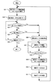
次に、第1の実施形態に係るネットワークカメラの動作について、図3に示すフローチャートを参照しながら説明する。 Next, the operation of the network camera according to the first embodiment will be described with reference to the flowchart shown in FIG.
本実施形態に係るネットワークカメラが監視撮影を開始すると、先ず、制御部101は切換部104をカメラ102に接続し、更にカメラ102に第1の電源105の供給を開始して、監視画像の撮影を開始する(ステップS1)。
When the network camera according to the present embodiment starts monitoring shooting, first, the
カメラ102により撮影され信号処理部115から出力された画像データは、動き検出部109及び符号化部108に送られ、動き検出部109は動き検出の処理を開始し、符号化部108は画像データのJPEG圧縮を開始する(ステップS2)。また、撮影が開始されると(ステップS1)、メモリ110内にリングバッファ領域が確保され、符号化部108によってJPEG圧縮されたデータがリングバッファ領域に順次書き込まれていく。なお、リングバッファ領域には、信号処理部115から出力された画像を1分間分蓄積可能な容量が確保され、リングバッファ領域の最後までデータを書き込むと、先頭に戻ってデータを上書きしていく。
The image data shot by the
カメラ102を用いた撮影が行われている間、制御部101は外部センサからセンサ入力検出部112へのトリガ入力があるか否かを判定し(ステップS3)、外部センサからのトリガ入力がない場合は、更に動き検出部109からの動き検出に基づくトリガ入力があるか否かを判定する(ステップS4)。
While photographing using the
そして、動き検出に基づくトリガ入力もない場合、制御部101は撮影動作の終了判定を行い(ステップS5)、撮影終了でなければ、再びステップS3の外部センサからのトリガ入力判定処理を行う。ステップS5において、制御部101は、例えば、操作部(図示せず)から操作者がネットワークカメラの撮影終了のための操作を行った場合、インターネット経由で遠隔地の通信端末から撮影終了のための操作メッセージを受信した場合、又は、予め操作者がネットワークカメラに設定した終了時間が経過した場合に、撮影動作の終了と判定する。
If there is no trigger input based on motion detection, the
外部センサからのトリガ入力があった場合、又は動き検出部109から動き検出トリガが入力された場合、制御部101は、カメラ102の撮影を停止させると共に(ステップS6)、第1の電源105の供給を停止する。更に、制御部101は、切換部104の接続をカメラ103に切り換え、第2の電源106をカメラ103に供給し、カメラ103が撮影を開始する(ステップS7)。
When there is a trigger input from an external sensor, or when a motion detection trigger is input from the
カメラ103により撮影され信号処理部118から出力された画像データは、予め操作者が設定した画像サイズに解像度変換部107によって解像度変換され、更に符号化部108によってJPEG圧縮され、予め設定された時間のMotionJPEGファイルとしてメモリ110に蓄積される。
The image data photographed by the
そして、カメラ103による撮影を開始してから、予め設定された時間だけ経過すると(ステップS8)、撮影動作を停止して(ステップS9)、撮影データの合成処理を行う(ステップS10)。撮影データの合成処理(ステップS10)では、先ず、制御部101が、リングバッファ領域に蓄積されているカメラ102が撮影した1分間分の撮影画像データを読み出し、符号化部108がJPEG方式で復号化する。次に、解像度変換部107が、復号化されたデータをカメラ103による撮影に設定された画像サイズと同じサイズに変換する。次いで、符号化部108が、サイズの変換が行なわれたデータをJPEG符号化し、制御部101がメモリ110に蓄積する。そして、このメモリ110に蓄積されたデータに、カメラ103による撮影で取得した撮影データを合成し、1つの連続したMotionJPEGの撮影データのファイルにする。
Then, when a preset time has elapsed since the start of shooting by the camera 103 (step S8), the shooting operation is stopped (step S9), and shooting data composition processing is performed (step S10). In the photographic data composition process (step S10), first, the
このような合成処理(ステップS10)を行った後、制御部101は、合成処理により得られたファイルを、例えば、通信部111を介して遠隔地の通信端末に電子メールの添付ファイルとして添付して送信する(ステップS11)。
After performing such synthesis processing (step S10), the
これらのステップS6〜S11の処理が終了すると、再びカメラ102による撮影(ステップS1)に戻り、トリガ入力の待機状態として、トリガ検出の判定処理S3〜S5を繰り返す。 When the processes in steps S6 to S11 are completed, the process returns to the shooting by the camera 102 (step S1) again, and the trigger detection determination processes S3 to S5 are repeated as a trigger input standby state.
このような第1の実施形態では、センサ入力が検出されるか、又は動きが検出されるまでの待機状態の間は、低消費電力のカメラ102が動作し、高解像度で高消費電力のカメラ103は動作していない。そして、センサ入力が検出されるか、又は動きが検出されて初めてカメラ103が動作する。従って、待機中の消費電力を低減することができる。
In the first embodiment, the low-
(第2の実施形態)
次に、本発明の第2の実施形態について説明する。近年、1つのCCDで解像度の異なる画素読み出しが可能な間引きモード付CCDがある。そこで、第1の実施形態では、2個のカメラ102及び103を用いて第1及び第2の撮影手段としているのに対し、第2の実施形態では、このような間引きモード付CCDを用いて、1つのカメラで第1及び第2の撮影手段を実現する。図5は、本発明の第2の実施形態に係るネットワークカメラ(撮影装置)の構成を示すブロック図である。
(Second Embodiment)
Next, a second embodiment of the present invention will be described. In recent years, there is a CCD with a thinning mode that enables pixel readout with different resolutions with one CCD. Therefore, in the first embodiment, two
図5において、500はネットワークカメラ本体、501は制御部、502はカメラ部、503は切換部、504は解像度変換部、505は符号化部、506は動き検出部、507はメモリ、508はPHS通信部、509はセンサ入力検出部、510はレンズ、511は間引きモード付きCCD(第1及び第2の撮影手段)、512は信号処理部、513はレンズのフォーカス機構駆動用のモータ、514は間引きモードで読み出したCCD信号、515は全撮像素子を読み出したCCD信号、516はモータ駆動信号、517はアンテナ、518はPHSの基地局、519はPHS通信網、520アクセスポイント、521はインターネットを、夫々示している。 In FIG. 5, 500 is a network camera body, 501 is a control unit, 502 is a camera unit, 503 is a switching unit, 504 is a resolution conversion unit, 505 is an encoding unit, 506 is a motion detection unit, 507 is a memory, and 508 is a PHS. A communication unit, 509 is a sensor input detection unit, 510 is a lens, 511 is a CCD with a thinning mode (first and second photographing means), 512 is a signal processing unit, 513 is a motor for driving a lens focusing mechanism, and 514 is CCD signal read in thinning mode, 515 CCD signal read from all image sensors, 516 motor drive signal, 517 antenna, 518 PHS base station, 519 PHS communication network, 520 access point, 521 Internet , Respectively.
ここで、解像度の異なる読み出しが可能な間引きモード付CCDについて、図4を参照しながら説明する。図4は、水平ラインを1/8に間引く間引きモード付CCDの各撮像素子の配置を示す模式図である。 Here, a CCD with a thinning mode capable of reading with different resolutions will be described with reference to FIG. FIG. 4 is a schematic diagram showing the arrangement of each image sensor of a CCD with a thinning mode that thins out horizontal lines to 1/8.
図4の上から、第1ライン目の撮像素子列、第2ライン目の撮像素子列、第3ライン目の撮像素子列、・・・と順次撮像素子が並んで配置されており、通常のフレーム読み出し時には、これら全ての撮像素子の電荷がライン毎に読み出される。 From the top of FIG. 4, the first image pickup device row, the second line image pickup device row, the third line image pickup device row,... At the time of frame reading, the charges of all these image sensors are read for each line.
一方、間引きモード時の読み出しは、先ず、第1ライン目の撮像素子列の電荷が読み出され、次に、第9ライン目の撮像素子列の電荷が読み出され、その後、第(8n+1)ライン目(nは自然数)の撮像素子列の電荷が順次読み出される。 On the other hand, in the readout in the thinning mode, first, the charge of the image sensor array on the first line is read, then the charge of the image sensor array on the ninth line is read, and then (8n + 1) th. The charges in the image sensor array on the line (n is a natural number) are sequentially read out.
このようにラインを間引いて読み出すことで、同じ読み出しクロックで1フレームの全撮像素子から信号を読み出す場合と比べて、1フレームの撮像素子から信号を読み出す時間が短縮されるので、結果として、1フレームを読み出すために必要な消費電力が低減される。更に、間引きモード時には、使用する撮像素子数が少なくなるので、CCDからの読み出し電荷をデータ処理する信号処理部512の処理負荷も軽減され、信号処理部512の消費電力も低減される。
By thinning out the lines in this way and reading out signals from all image sensors of one frame with the same readout clock, the time for reading out signals from the image sensor of one frame is shortened. The power consumption required to read the frame is reduced. Further, in the thinning mode, since the number of image sensors to be used is reduced, the processing load of the
このようなCCDの間引きモードでは、CCDから読み出される水平方向のライン数が間引かれているが、垂直方向の撮像素子の信号は全て読み出されており、CCD出力の後段に接続されている信号処理部512で垂直方向の画素を加算平均して間引きし、水平方向の間引き率と同じ間引き率で垂直方向の画素を生成する。
In such a CCD thinning mode, the number of horizontal lines read out from the CCD is thinned out, but all signals from the vertical image sensor are read out and connected to the subsequent stage of CCD output. The
本実施形態には、上述のような間引きモードを備えたCCD511が設けられているのである。
In this embodiment, the
PHS通信部508で使用するPHSとは、Personal Handyphone Systemの略称であり、携帯電話と同様、公衆無線通信システムの一種である。
The PHS used in the
CCD511から読み出す信号は、間引きモードでも全画素モードでも電気的に同一の配線を経由して信号処理部512に入力されるが、図4では、概念の説明のため、別バスとして間引きモードのCCD信号514と全画素モードのCCD信号515とを区別して示している。
A signal read from the
信号処理部512は、CCD511が間引きモードで動作しているときは、CCD511から出力された画素信号をAD変換し、更に176×144画素の画像サイズの色信号Yと色差信号Cr及びCbとに変換する。また、信号処理部512は、CCD511が通常の全画素読み出しモードで動作しているときは、CCD511から出力された画素信号をAD変換し、更に1600×1200画素の画像サイズの色信号Yと色差信号Cr及びCbとに変換する。
When the
切換部503は、制御部501によって制御される概念的な切換手段であって、CCD511から出力される間引きモード時の画素信号と、通常の全画素読み出しモード時の画素信号のいずれかを制御部501が選択する機能を示している。実際には、前述のように、信号処理部512から出力される信号の電気的な配線は1つである。
The
解像度変換部504は、信号処理部512から出力された画像信号のフレームサイズを変換する機能を備えている。解像度変換部504は、例えば、信号処理部512から出力された176×144画素の画像データ又は1600×1200画素の画像データを、QCIFサイズの176×144画素、CIFサイズの352×288画素、又は、VGAの640×480画素、1024×768画素若しくは1600×1200画素のいずれかのサイズの画像データに変換する。
The
解像度変換部504は、符号化部505によって復号化された画像データに対しても、上記と同様の解像度変換処理を行うことができる。
The
符号化部505、動き検出部506及びセンサ入力検出部509は、夫々第1の実施形態における符号化部108、動き検出部109及びセンサ部112と同様の処理動作を行う。
The
PHS通信部508は、前述したPHS通信網に接続する無線通信処理部で、携帯電話と同様に、1台ずつに特定な加入者番号を備え、PHS通信網519は加入者番号情報に従ってPHS通信網への接続許可及び課金を制御する。
The
そして、本実施形態に係るネットワークカメラ500は、PHS通信部508でPHS通信網519に接続し、インターネット521に接続するためのアクセスポイント520との通信路を確立することで、インターネット521との接続が可能となる。
The
次に、第2の実施形態に係るネットワークカメラの動作について、図6に示すフローチャートを参照しながら説明する。 Next, the operation of the network camera according to the second embodiment will be described with reference to the flowchart shown in FIG.
本実施形態に係るネットワークカメラが監視撮影を開始すると、先ず、制御部501は切換部503を間引きモードのパスに接続し、更にカメラ502に電源(図示せず)の供給を開始して、監視画像の撮影を開始する(ステップS21)。
When the network camera according to the present embodiment starts monitoring shooting, first, the
カメラ502により撮影され信号処理部512から出力された画像データは、動き検出部506及び符号化部505に送られ、動き検出部506は動き検出の処理を開始し、符号化部505は画像データのJPEG圧縮を開始する(ステップS22)。また、撮影が開始されると(ステップS21)、メモリ507内にリングバッファ領域が確保され、符号化部505によってJPEG圧縮されたデータがリングバッファ領域に順次書き込まれていく。なお、リングバッファ領域には、信号処理部512から出力された画像を1分間分蓄積可能な容量が確保され、リングバッファ領域の最後までデータを書き込むと、先頭に戻ってデータを上書きしていく。
The image data shot by the
また、間引きモードの撮影が開始されると、制御部501はレンズ510のフォーカスが2mになるようにモータ513を駆動して固定し、間引きモードでの撮影中は、モータ駆動を停止してカメラ502での消費電力を抑制する。
In addition, when shooting in the thinning mode is started, the
また、間引きモードでの撮影が行われている間、制御部501は外部センサからセンサ入力検出部509へのトリガ入力があるか否かを判定し(ステップS23)、外部センサからのトリガ入力がない場合は、更に動き検出部506からの動き検出に基づくトリガ入力があるか否かを判定する(ステップS24)。
Further, while photographing in the thinning mode is performed, the
そして、動き検出に基づくトリガ入力もない場合、制御部501は撮影動作の終了判定を行い(ステップS25)、撮影終了でなければ、再びステップS23の外部センサからのトリガ入力判定処理を行う。ステップS25において、制御部501は、例えば、操作部(図示せず)から操作者がネットワークカメラの撮影終了のための操作を行った場合、インターネット経由で遠隔地の通信端末から撮影終了のための操作メッセージを受信した場合、又は、予め操作者がネットワークカメラに設定した終了時間が経過した場合に、撮影動作の終了と判定する。
If there is no trigger input based on motion detection, the
外部センサからのトリガ入力があった場合、又は動き検出部506から動き検出トリガが入力された場合、制御部501は、間引きモードの撮影を停止させると共に(ステップS26)、切換部503の接続を通常モードに切替えて撮影を開始する(ステップS27)。
When there is a trigger input from an external sensor or when a motion detection trigger is input from the
通常モードの撮影が開始されると、制御部501はフォーカス機構駆動用のモータ513の制御を行い、通常モード撮影が行われている間、オートフォーカス機能を作動させる。
When the normal mode shooting is started, the
その後、通常モードで撮影され信号処理部512から出力された画像データは、予め操作者が設定した画像サイズに解像度変換部504によって解像度変換され、更に符号化部505によってJPEG圧縮され、予め設定された時間のMotionJPEGファイルとしてメモリ507に蓄積される。
Thereafter, the image data captured in the normal mode and output from the
そして、通常モードによる撮影を開始してから、予め設定された時間だけ経過すると(ステップS28)、通常モードの撮影を停止すると共に、フォーカスを2mに設定した後フォーカス機構駆動用モータの動作を停止して(ステップS29)、撮影データの合成処理を行う(ステップS30)。撮影データの合成処理(ステップS30)では、先ず、制御部501が、リングバッファ領域に蓄積されている間引きモードで撮影した1分間分の撮影画像データを読み出し、符号化部505がJPEG方式で復号化する。次に、解像度変換部504が、復号化されたデータを通常モードの撮影に設定された画像サイズと同じサイズに変換する。次いで、符号化部505が、サイズの変換が行なわれたデータをJPEG符号化し、制御部501がメモリ507に蓄積する。そして、このメモリ507に蓄積されたデータに、通常モードで撮影した撮影データを合成し、1つの連続したMotionJPEGの撮影データのファイルにする。
Then, when a preset time has elapsed since the start of shooting in the normal mode (step S28), the shooting in the normal mode is stopped and the focus mechanism driving motor is stopped after the focus is set to 2 m. Then (step S29), the photographing data composition processing is performed (step S30). In the shooting data composition processing (step S30), first, the
このような合成処理(ステップS30)を行った後、制御部501は、合成処理により得られたファイルを、例えば、PHS通信部508を介してインターネット上の通信端末に電子メールの添付ファイルとして添付して送信する(ステップS31)。
After performing such a synthesis process (step S30), the
これらのステップS26〜S31の処理が終了すると、再び間引きモードによる撮影(ステップS21)に戻り、トリガ入力の待機状態として、トリガ検出の判定処理S23〜S25を繰り返す。 When the processes of steps S26 to S31 are completed, the process returns to the imaging in the thinning mode (step S21) again, and the trigger detection determination processes S23 to S25 are repeated as a trigger input standby state.
このような第2の実施形態によっても、第1の実施形態と同様の効果を得ることができる。また、内蔵するカメラが1台であるため、機械的な構造をより簡素にすることができる。 Also by such 2nd Embodiment, the effect similar to 1st Embodiment can be acquired. Further, since there is one built-in camera, the mechanical structure can be further simplified.
なお、第1及び第2の実施形態では、トリガ発生後の第2の撮影手段による撮影を予め設定された時間経過した後に終了させているが、動き検出部が動きを検出している間は、経過時間に拘わらず、撮影を継続するようにしてもよい。 In the first and second embodiments, the shooting by the second shooting unit after the trigger is generated is terminated after a preset time has elapsed, while the motion detection unit detects the motion. The shooting may be continued regardless of the elapsed time.
また、動き検出部による動き検出の方法は、上記の実施形態のものに限定されるものではなく、他の方法により動き検出を行ってもよい。また、撮影手段の撮像素子はCCDに限定されず、例えば、CMOS撮像素子であってもよいし、その他の撮像素子であってもよい。更に、符号化部による圧縮方式はJPEG以外の静止画圧縮方式であってもよく、例えばMPEG4、MPEG2等の動画符号化方式であってもよい。また、インターネット等のネットワークとの接続方式も特に限定されない。 Further, the method of motion detection by the motion detection unit is not limited to that of the above embodiment, and motion detection may be performed by other methods. Further, the image pickup device of the photographing unit is not limited to the CCD, and may be, for example, a CMOS image pickup device or other image pickup device. Furthermore, the compression method by the encoding unit may be a still image compression method other than JPEG, for example, a moving image encoding method such as MPEG4 or MPEG2. Further, the connection method with a network such as the Internet is not particularly limited.
本発明の実施形態は、例えばコンピュータがプログラムを実行することによって実現することができる。また、プログラムをコンピュータに供給するための手段、例えばかかるプログラムを記録したCD−ROM等のコンピュータ読み取り可能な記録媒体又はかかるプログラムを伝送するインターネット等の伝送媒体も本発明の実施形態として適用することができる。また、上記のプログラムも本発明の実施形態として適用することができる。上記のプログラム、記録媒体、伝送媒体及びプログラムプロダクトは、本発明の範疇に含まれる。 The embodiment of the present invention can be realized by, for example, a computer executing a program. Also, means for supplying a program to a computer, for example, a computer-readable recording medium such as a CD-ROM recording such a program, or a transmission medium such as the Internet for transmitting such a program is also applied as an embodiment of the present invention. Can do. The above program can also be applied as an embodiment of the present invention. The above program, recording medium, transmission medium, and program product are included in the scope of the present invention.
101、501:制御部
102:第1のカメラ
103:第2のカメラ
109、506:動き検出部
110、507:メモリ
112、509:センサ入力検出部
114:第1のCCD
115:第1の信号処理部
117:第2のCCD
118:第2の信号処理部
502:カメラ
511:CCD
512:信号処理部
101, 501: Control unit 102: First camera 103:
115: First signal processing unit 117: Second CCD
118: Second signal processing unit 502: Camera 511: CCD
512: Signal processing unit
Claims (8)
前記第1の撮影手段よりも高い解像度で画像を撮影する第2の撮影手段と、
予め設定された条件が満たされたか否かの判定を行う条件判定手段と、
を有し、
前記条件判定手段が前記条件が満たされたと判定するまでは前記第1の撮影手段で画像を撮影し、
前記条件判定手段が前記条件が満たされたと判定した後は前記第2の撮影手段で画像を撮影することを特徴とする撮影装置。 A first photographing means for photographing an image;
A second photographing means for photographing an image at a higher resolution than the first photographing means;
Condition determination means for determining whether or not a preset condition is satisfied;
Have
Until the condition determination unit determines that the condition is satisfied, the first imaging unit captures an image,
An imaging apparatus characterized in that after the condition determining means determines that the condition is satisfied, the second imaging means captures an image.
前記状態変化検出手段が状態変化を検出するまでは前記第1の撮影手段で画像を撮影し、
前記状態変化検出手段が状態変化を検出した後は前記第2の撮影手段で画像を撮影することを特徴とする請求項1に記載の撮影装置。 As the condition determining means, there is a state change detecting means for detecting a state change of an image taken by the first image,
Until the state change detecting means detects the state change, the first photographing means takes an image,
The imaging apparatus according to claim 1, wherein after the state change detection unit detects a state change, the second imaging unit captures an image.
前記入力変化検出手段が前記入力信号の変化を検出するまでは前記第1の撮影手段で画像を撮影し、
前記入力変化検出手段が前記入力信号の変化を検出した後は前記第2の撮影手段で画像を撮影することを特徴とする請求項1に記載の撮影装置。 As the condition determination means, it has an input change detection means for detecting a change in an input signal from the outside,
Until the input change detecting means detects a change in the input signal, the first photographing means captures an image,
The imaging apparatus according to claim 1, wherein after the input change detection unit detects a change in the input signal, the second imaging unit captures an image.
前記第1の画像が撮影している画像の状態変化を検出する状態変化検出手段と、
外部からの入力信号の変化を検出する入力変化検出手段と、
を有し、
前記入力変化検出手段が前記入力信号の変化を検出するか、又は前記入力変化検出手段が前記入力信号の変化を検出するまでは前記第1の撮影手段で画像を撮影し、
前記入力変化検出手段が前記入力信号の変化を検出するか、又は前記入力変化検出手段が前記入力信号の変化を検出した後は前記第2の撮影手段で画像を撮影することを特徴とする請求項1に記載の撮影装置。 As the condition determining means,
State change detecting means for detecting a state change of an image captured by the first image;
An input change detecting means for detecting a change in an input signal from the outside;
Have
Until the input change detection means detects a change in the input signal or until the input change detection means detects a change in the input signal, the first photographing means takes an image,
The input change detection unit detects a change in the input signal, or the second change shooting unit captures an image after the input change detection unit detects a change in the input signal. Item 2. The photographing apparatus according to Item 1.
前記条件判定手段が前記条件が満たされたと判定した後は前記第2の撮影手段で撮影した画像のデータを記録し、
前記条件判定手段が前記条件が満たされたと判定してから予め定められた時間が経過した後に、
前記第1の撮影手段で撮影した画像のデータのうち、前記条件判定手段が前記条件が満たされたと判定した時から予め定められた時間だけ前の時刻までのデータと、前記第2の撮影手段で撮影した画像のデータと、を結合して1つの蓄積画像を生成することを特徴とする請求項1乃至4のいずれか1項に記載の撮影装置。 Until the condition determination unit determines that the condition is satisfied, the image data captured by the first imaging unit is recorded,
After the condition determining means determines that the condition is satisfied, it records the image data captured by the second imaging means,
After a predetermined time has elapsed since the condition determining means determined that the condition was satisfied,
Of the data of the image photographed by the first photographing means, the data from the time when the condition judging means judges that the condition is satisfied to the time before a predetermined time, and the second photographing means The image capturing apparatus according to any one of claims 1 to 4, wherein the data of the image captured in step (1) is combined to generate one accumulated image.
予め設定された条件が満たされたか否かの判定を行う条件判定ステップと、
前記条件が満たされるまでは前記第1の撮影手段で画像を撮影させ、前記条件が満たされた後は前記第2の撮影手段で画像を撮影させる撮影切り換えステップと、
を有することを特徴とする撮影装置の制御方法。 A method for controlling the operation of a photographing apparatus having a first photographing means for photographing an image and a second photographing means for photographing an image with a higher resolution than the first photographing means,
A condition determination step for determining whether or not a preset condition is satisfied;
A shooting switching step of shooting an image with the first shooting means until the condition is satisfied, and shooting an image with the second shooting means after the condition is satisfied;
A method for controlling an imaging apparatus, comprising:
コンピュータに、
予め設定された条件が満たされたか否かの判定を行う条件判定手順と、
前記条件判定手段が前記条件が満たされたと判定するまでは前記第1の撮影手段で画像を撮影させ、前記条件判定手段が前記条件が満たされたと判定した後は前記第2の撮影手段で画像を撮影させる撮影切り換え手順と、
を実行させることを特徴とするプログラム。 A program for controlling the operation of a photographing apparatus having a first photographing means for photographing an image and a second photographing means for photographing an image with a higher resolution than the first photographing means,
On the computer,
A condition determination procedure for determining whether or not a preset condition is satisfied;
Until the condition determining unit determines that the condition is satisfied, the first image capturing unit captures an image. After the condition determining unit determines that the condition is satisfied, the second image capturing unit captures an image. A shooting switching procedure for shooting
A program characterized by having executed.
前記プログラムは、コンピュータに、
予め設定された条件が満たされたか否かの判定を行う条件判定手順と、
前記条件判定手段が前記条件が満たされたと判定するまでは前記第1の撮影手段で画像を撮影させ、前記条件判定手段が前記条件が満たされたと判定した後は前記第2の撮影手段で画像を撮影させる撮影切り換え手順と、
を実行させるためのプログラムであることを特徴とするコンピュータ読み取り可能な記録媒体。
A computer-readable recording of a program for controlling the operation of an imaging apparatus having a first imaging unit for imaging an image and a second imaging unit for imaging an image at a higher resolution than the first imaging unit A possible recording medium,
The program is stored in a computer.
A condition determination procedure for determining whether or not a preset condition is satisfied;
Until the condition determining unit determines that the condition is satisfied, the first image capturing unit captures an image. After the condition determining unit determines that the condition is satisfied, the second image capturing unit captures an image. A shooting switching procedure for shooting
A computer-readable recording medium characterized by being a program for executing
Priority Applications (1)
| Application Number | Priority Date | Filing Date | Title |
|---|---|---|---|
| JP2004099208A JP2005286770A (en) | 2004-03-30 | 2004-03-30 | Imaging device and its control method |
Applications Claiming Priority (1)
| Application Number | Priority Date | Filing Date | Title |
|---|---|---|---|
| JP2004099208A JP2005286770A (en) | 2004-03-30 | 2004-03-30 | Imaging device and its control method |
Publications (2)
| Publication Number | Publication Date |
|---|---|
| JP2005286770A true JP2005286770A (en) | 2005-10-13 |
| JP2005286770A5 JP2005286770A5 (en) | 2007-05-24 |
Family
ID=35184683
Family Applications (1)
| Application Number | Title | Priority Date | Filing Date |
|---|---|---|---|
| JP2004099208A Withdrawn JP2005286770A (en) | 2004-03-30 | 2004-03-30 | Imaging device and its control method |
Country Status (1)
| Country | Link |
|---|---|
| JP (1) | JP2005286770A (en) |
Cited By (9)
| Publication number | Priority date | Publication date | Assignee | Title |
|---|---|---|---|---|
| JP2007318262A (en) * | 2006-05-23 | 2007-12-06 | Sanyo Electric Co Ltd | Imaging apparatus |
| JP2008271349A (en) * | 2007-04-24 | 2008-11-06 | Hitachi Ltd | Monitoring record playback system |
| DE102011003392A1 (en) | 2011-01-31 | 2012-08-02 | Fraunhofer-Gesellschaft zur Förderung der angewandten Forschung e.V. | Video recording system and method for video recording |
| CN104410785A (en) * | 2014-11-17 | 2015-03-11 | 联想(北京)有限公司 | An information processing method and electronic device |
| CN104601888A (en) * | 2015-01-19 | 2015-05-06 | 联想(北京)有限公司 | Control method and electronic equipment |
| CN106161916A (en) * | 2015-04-08 | 2016-11-23 | 联想(北京)有限公司 | A kind of image-pickup method and electronic equipment |
| CN108024056A (en) * | 2017-11-30 | 2018-05-11 | 广东欧珀移动通信有限公司 | Imaging method and device based on dual camera |
| WO2018126671A1 (en) * | 2017-01-04 | 2018-07-12 | 中兴通讯股份有限公司 | Intelligent photographing method and apparatus, and intelligent terminal |
| WO2018176214A1 (en) * | 2017-03-28 | 2018-10-04 | 杭州如道科技有限公司 | Split high-resolution network camera |
-
2004
- 2004-03-30 JP JP2004099208A patent/JP2005286770A/en not_active Withdrawn
Cited By (13)
| Publication number | Priority date | Publication date | Assignee | Title |
|---|---|---|---|---|
| JP2007318262A (en) * | 2006-05-23 | 2007-12-06 | Sanyo Electric Co Ltd | Imaging apparatus |
| JP2008271349A (en) * | 2007-04-24 | 2008-11-06 | Hitachi Ltd | Monitoring record playback system |
| DE102011003392A1 (en) | 2011-01-31 | 2012-08-02 | Fraunhofer-Gesellschaft zur Förderung der angewandten Forschung e.V. | Video recording system and method for video recording |
| CN104410785B (en) * | 2014-11-17 | 2019-01-15 | 联想(北京)有限公司 | A kind of information processing method and electronic equipment |
| CN104410785A (en) * | 2014-11-17 | 2015-03-11 | 联想(北京)有限公司 | An information processing method and electronic device |
| CN104601888A (en) * | 2015-01-19 | 2015-05-06 | 联想(北京)有限公司 | Control method and electronic equipment |
| CN106161916A (en) * | 2015-04-08 | 2016-11-23 | 联想(北京)有限公司 | A kind of image-pickup method and electronic equipment |
| CN106161916B (en) * | 2015-04-08 | 2019-10-29 | 联想(北京)有限公司 | A kind of image-pickup method and electronic equipment |
| WO2018126671A1 (en) * | 2017-01-04 | 2018-07-12 | 中兴通讯股份有限公司 | Intelligent photographing method and apparatus, and intelligent terminal |
| WO2018176214A1 (en) * | 2017-03-28 | 2018-10-04 | 杭州如道科技有限公司 | Split high-resolution network camera |
| CN108024056A (en) * | 2017-11-30 | 2018-05-11 | 广东欧珀移动通信有限公司 | Imaging method and device based on dual camera |
| CN108024056B (en) * | 2017-11-30 | 2019-10-29 | Oppo广东移动通信有限公司 | Imaging method and device based on dual camera |
| US10742860B2 (en) | 2017-11-30 | 2020-08-11 | Guangdong Oppo Mobile Telecommunications Corp., Ltd. | Method and device for double-camera-based imaging |
Similar Documents
| Publication | Publication Date | Title |
|---|---|---|
| JP6240642B2 (en) | Method and apparatus for providing image of image capturing apparatus | |
| JP4525561B2 (en) | Imaging apparatus, image processing method, and program | |
| JP3839526B2 (en) | Digital camera | |
| US20130258136A1 (en) | Image processing apparatus and method of camera device | |
| US20100321530A1 (en) | Apparatus and method for reducing shutter lag of a digital camera | |
| JP2006325150A (en) | Method, system and apparatus for imaging | |
| JP2006253768A (en) | Digital camera | |
| JP4856712B2 (en) | Surveillance video storage system | |
| KR101611531B1 (en) | Camera apparatus and method for providing recorded image | |
| KR100770835B1 (en) | Image data processing system and it's method | |
| JP2005286770A (en) | Imaging device and its control method | |
| WO2011024361A1 (en) | Network camera and video distribution system | |
| JP4337541B2 (en) | Camera device, monitoring system, and camera device control method | |
| US7705890B2 (en) | Apparatus and method for photographing an image in a wireless terminal | |
| JP5024331B2 (en) | Video camera and information transmission method | |
| JP2007228119A (en) | Imaging apparatus, image processing method, and program | |
| JP5223974B2 (en) | Video camera and control method thereof | |
| JP2006101227A (en) | Imaging apparatus and imaging system | |
| JP4306555B2 (en) | Video camera | |
| JP4465655B2 (en) | Video camera and information transmission method | |
| JP2003174640A (en) | Image photographing system, photographing apparatus, and photographing controller | |
| JP2005295247A (en) | Network camera | |
| JP2001036793A (en) | Video camera | |
| JP2003110924A (en) | Electronic camera | |
| JP2009135997A (en) | Video camera and control method thereof |
Legal Events
| Date | Code | Title | Description |
|---|---|---|---|
| A521 | Request for written amendment filed |
Free format text: JAPANESE INTERMEDIATE CODE: A523 Effective date: 20070327 |
|
| A621 | Written request for application examination |
Free format text: JAPANESE INTERMEDIATE CODE: A621 Effective date: 20070327 |
|
| A761 | Written withdrawal of application |
Free format text: JAPANESE INTERMEDIATE CODE: A761 Effective date: 20071203 |