JP2005285254A - Recording method of optical disk, and optical disk - Google Patents
Recording method of optical disk, and optical disk Download PDFInfo
- Publication number
- JP2005285254A JP2005285254A JP2004099616A JP2004099616A JP2005285254A JP 2005285254 A JP2005285254 A JP 2005285254A JP 2004099616 A JP2004099616 A JP 2004099616A JP 2004099616 A JP2004099616 A JP 2004099616A JP 2005285254 A JP2005285254 A JP 2005285254A
- Authority
- JP
- Japan
- Prior art keywords
- recording
- test
- area
- layer
- recording layer
- Prior art date
- Legal status (The legal status is an assumption and is not a legal conclusion. Google has not performed a legal analysis and makes no representation as to the accuracy of the status listed.)
- Pending
Links
Images


Classifications
-
- G—PHYSICS
- G11—INFORMATION STORAGE
- G11B—INFORMATION STORAGE BASED ON RELATIVE MOVEMENT BETWEEN RECORD CARRIER AND TRANSDUCER
- G11B7/00—Recording or reproducing by optical means, e.g. recording using a thermal beam of optical radiation by modifying optical properties or the physical structure, reproducing using an optical beam at lower power by sensing optical properties; Record carriers therefor
- G11B7/004—Recording, reproducing or erasing methods; Read, write or erase circuits therefor
- G11B7/0045—Recording
-
- G—PHYSICS
- G11—INFORMATION STORAGE
- G11B—INFORMATION STORAGE BASED ON RELATIVE MOVEMENT BETWEEN RECORD CARRIER AND TRANSDUCER
- G11B7/00—Recording or reproducing by optical means, e.g. recording using a thermal beam of optical radiation by modifying optical properties or the physical structure, reproducing using an optical beam at lower power by sensing optical properties; Record carriers therefor
- G11B7/12—Heads, e.g. forming of the optical beam spot or modulation of the optical beam
- G11B7/125—Optical beam sources therefor, e.g. laser control circuitry specially adapted for optical storage devices; Modulators, e.g. means for controlling the size or intensity of optical spots or optical traces
- G11B7/126—Circuits, methods or arrangements for laser control or stabilisation
- G11B7/1267—Power calibration
-
- G—PHYSICS
- G11—INFORMATION STORAGE
- G11B—INFORMATION STORAGE BASED ON RELATIVE MOVEMENT BETWEEN RECORD CARRIER AND TRANSDUCER
- G11B7/00—Recording or reproducing by optical means, e.g. recording using a thermal beam of optical radiation by modifying optical properties or the physical structure, reproducing using an optical beam at lower power by sensing optical properties; Record carriers therefor
- G11B7/007—Arrangement of the information on the record carrier, e.g. form of tracks, actual track shape, e.g. wobbled, or cross-section, e.g. v-shaped; Sequential information structures, e.g. sectoring or header formats within a track
- G11B7/00736—Auxiliary data, e.g. lead-in, lead-out, Power Calibration Area [PCA], Burst Cutting Area [BCA], control information
-
- G—PHYSICS
- G11—INFORMATION STORAGE
- G11B—INFORMATION STORAGE BASED ON RELATIVE MOVEMENT BETWEEN RECORD CARRIER AND TRANSDUCER
- G11B7/00—Recording or reproducing by optical means, e.g. recording using a thermal beam of optical radiation by modifying optical properties or the physical structure, reproducing using an optical beam at lower power by sensing optical properties; Record carriers therefor
- G11B7/24—Record carriers characterised by shape, structure or physical properties, or by the selection of the material
- G11B7/2403—Layers; Shape, structure or physical properties thereof
- G11B7/24035—Recording layers
- G11B7/24038—Multiple laminated recording layers
Abstract
Description
本発明は、光ディスクの記録方法及び光ディスクに関する。本発明は、特に複数の記録層を有する光ディスクの記録方法に関し、特に各記録層に於ける最適記録パワーを決定するためのテストデータの記録に関する。本発明はまた、上記記録方法で記録に用いられる光ディスク及び上記の記録方法で記録が行われた光ディスクに関する。 The present invention relates to an optical disc recording method and an optical disc. The present invention relates to a recording method for an optical disc having a plurality of recording layers, and more particularly to recording test data for determining an optimum recording power in each recording layer. The present invention also relates to an optical disc used for recording by the recording method and an optical disc recorded by the recording method.
従来の複数の記録層を有する光ディスクの記録方法においては、各記録層にテスト記録を行う際、テスト記録領域を互いに隣接する記録層間で厚さ方向に重なり合う位置に形成していた。そして、隣接する記録層の影響を考慮せずに各記録層毎に最適記録パワーを決定していた。その結果、隣接する層の影響により、決定された最適記録パワーが真値から若干ずれる場合があった。 In the conventional recording method of an optical disc having a plurality of recording layers, when performing test recording on each recording layer, the test recording area is formed at a position overlapping in the thickness direction between adjacent recording layers. Then, the optimum recording power is determined for each recording layer without considering the influence of the adjacent recording layers. As a result, the determined optimum recording power may deviate slightly from the true value due to the influence of adjacent layers.
この改善策として、情報(ユーザデータ)を記録する層以外の記録層、特に手前側(光ピックアップが設けられた側)に位置する記録層のテスト領域の使用状況を確認した後に、上記情報を記録する層のテスト記録を行う方法が提案された(例えば、特許文献1参照)。 As an improvement measure, after confirming the usage of the test area of the recording layer other than the layer for recording information (user data), particularly the recording layer located on the front side (side where the optical pickup is provided), the above information is A method of performing test recording of a recording layer has been proposed (see, for example, Patent Document 1).
しかし、上記特許文献1に記載された方法では、一つの記録層のテスト記録を行う際に、他の記録層のテスト記録領域の使用状況を確認するので、記録を開始するまでに長い時間を要すると言う問題があった。
本発明は、記録を開始するまでの時間を短くすることを目的とする。
However, in the method described in Patent Document 1, when performing test recording of one recording layer, the usage status of the test recording area of the other recording layer is confirmed, so a long time is required until recording is started. There was a problem that it was necessary.
An object of the present invention is to shorten the time until recording is started.
本発明は、
3層以上の記録層を有する光ディスクの記録方法において、
記録層の各々にユーザデータを記録する際の最適記録パワーを決定するためテストデータを記録し、再生し、再生結果を評価することにより前記最適記録パワーを求める工程を有し、
前記テストデータの記録によってテスト記録領域を形成するに当たり、奇数番目の記録層のテスト記録領域と偶数番目の記録層の前記テストデータが記録されるテスト記録領域とが互いに光ディスクの厚さ方向に重ならないようにし、奇数番目の記録層の前記テスト記録領域を互いに厚さ方向に整列させ、偶数番目の記録層の前記テスト記録領域を互いに厚さ方向に整列させる
ことを特徴とする光ディスクの記録方法を提供する。
The present invention
In a recording method of an optical disc having three or more recording layers,
Recording test data to determine the optimum recording power when recording user data on each of the recording layers, reproducing, and evaluating the reproduction result to obtain the optimum recording power,
In forming the test recording area by recording the test data, the test recording area of the odd-numbered recording layer and the test recording area of the even-numbered recording layer on which the test data is recorded overlap each other in the thickness direction of the optical disc. The test recording areas of the odd-numbered recording layers are aligned with each other in the thickness direction, and the test recording areas of the even-numbered recording layers are aligned with each other in the thickness direction. I will provide a.
このような記録方法によれば、互いに隣接する層間ではテスト記録領域が重ならないため、テスト記録時に隣接する記録層の使用状況を調査する必要がない。従って、記録を開始するまでの時間を短くすることができる。また、上記テスト記録領域の配置が、偶数番目の記録層用の配置と、奇数番目の記録層用の配置の2種類だけに統一されているので、一部に再生専用領域を備えた光ディスクなどの場合にその製造工程を簡単にすることができると言う効果がある。また、テスト記録を行う記録再生装置がコンピュータプログラムで動作する制御手段を有する場合、プログラムによる処理も奇数番目の記録層用と偶数番目の記録層用の2種類だけで対応可能であるので、プログラムを簡単にすることができる。 According to such a recording method, the test recording areas do not overlap between layers adjacent to each other, so that it is not necessary to investigate the use status of the adjacent recording layers during test recording. Therefore, it is possible to shorten the time until recording is started. Further, the arrangement of the test recording area is unified to only two types, that is, the arrangement for the even-numbered recording layer and the arrangement for the odd-numbered recording layer. In this case, the manufacturing process can be simplified. Further, when the recording / reproducing apparatus for performing test recording has a control means that operates by a computer program, the program can handle only two types of processing for the odd-numbered recording layer and for the even-numbered recording layer. Can be easy.
以下、図面を参照して本発明の実施の形態を説明する。
実施の形態1.
図1はこの発明の実施の形態1の記録方法によりテストデータが記録された光ディスクを示す概略平面図、図2は図1のII−II線に沿う概略断面図であり、図1における光ディスク上の各層のテスト記録領域の位置関係を示す概略断面図である。
Embodiments of the present invention will be described below with reference to the drawings.
Embodiment 1 FIG.
FIG. 1 is a schematic plan view showing an optical disk on which test data is recorded by the recording method according to Embodiment 1 of the present invention. FIG. 2 is a schematic cross-sectional view taken along the line II-II in FIG. It is a schematic sectional drawing which shows the positional relationship of the test recording area | region of each layer.
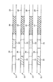
図1及び図2に示す光ディスク1には記録層が4層、即ち表面(光ピックアップに対向する側)に近い側から順に、第1、第2、第3、第4の記録層11、12、13、14が形成されている。第1、第2、第3、第4の記録層11、12、13、14には、それぞれの記録層に対する最適記録パワーを決定するためにテストデータが記録され、この記録によりテスト記録領域21、22、23、24が形成されている。
The optical disc 1 shown in FIGS. 1 and 2 has four recording layers, that is, first, second, third, and
表面側(図2で下側、即ち、後述の光ピックアップが設けられる側)から数えて奇数番目の記録層(以下、単に「奇数層」と言うことがある)、即ち第1及び第3の記録層11、13においては、互いに厚さ方向に整列した位置、即ち始点も終点も厚さ方向に整列するようにテスト記録領域21、23が形成され、偶数番目の記録層(以下、単に「偶数層」と言うことがある)、即ち第2及び第4の記録層12、14においては、互いに厚さ方向に整列した位置、即ち始点も終点も厚さ方向に整列するようにテスト記録領域22、24が形成されている。
また、奇数層のテスト記録領域21、23と偶数層のテスト記録領域22、24とは互いに重ならないように配置されている。
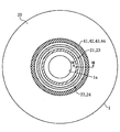
さらに、図1に示したように、奇数層のテスト記録領域と偶数層のテスト記録領域が共に光ディスクの最内周付近、即ち最内周縁1aの近傍に形成されている。
An odd-numbered recording layer (hereinafter sometimes simply referred to as “odd layer”) counted from the front side (the lower side in FIG. 2, that is, the side where an optical pickup described later) is provided, that is, the first and third In the
The odd-numbered
Further, as shown in FIG. 1, both the odd-numbered test recording area and the even-numbered test recording area are formed in the vicinity of the innermost periphery of the optical disk, that is, in the vicinity of the innermost periphery 1a.
テスト記録領域21、22、23、24に対向する領域(対向領域)、即ちディスクの厚さ方向に整列し、隣接する記録層内に位置する領域31、32,33、34は、光記録装置による記録をしない領域(非記録領域)とされている。言換えると、非記録領域31乃至34とテスト記録領域11乃至14とが互いに対向するようにテスト記録領域11乃至14の位置が定められている。非記録領域は例えば再生専用領域である。この再生専用領域は、例えばピットで構成されたものであり、例えばディスクの記録条件、例えばライトストラテジ推奨値、推奨亜シンメトリ値、波長推奨値などが記録されており、通常、テスト記録に先立ちこの再生専用領域に記録された上記のデータが読取られ、これに基づいてテスト記録の条件が定められる。
対向領域を再生専用領域とする場合には、ディスクの製造に当たっては、上記のようなテスト記録領域21乃至24の配置(形成予定位置)を考慮して、テスト記録領域21乃至24に対向することになる位置に再生専用領域を形成する。
テスト記録領域21乃至24と非記録領域31乃至34の間の領域30は、例えば管理データの記録のための領域として用いられる。
非記録領域31乃至34、管理データの記録のための領域30、及びテスト記録領域21乃至24以外の大部分が記録可能又は追記可能なユーザデータ領域20である。
The areas (opposite areas) facing the
When the opposite area is set as a read-only area, the disk should be opposed to the
An
Most of the areas other than the
図3は、光ディスクの記録に用いられる光記録装置を示す概略図である。
図示のように、この光記録装置は、光ディスク1の選択された記録層(11乃至14のいずれか)にレーザビームを照射するとともにその反射光を受光する光ピックアップ52と、光ピックアップ52のレーザ54にレーザ駆動信号を供給するレーザ駆動回路55と、光ピックアップ52に対物レンズ駆動信号を供給するサーボ制御回路56と、レーザ駆動回路55及びサーボ制御回路56を制御する中央制御回路58とを備えている。
FIG. 3 is a schematic diagram showing an optical recording apparatus used for recording on an optical disc.
As shown in the figure, this optical recording apparatus irradiates a selected recording layer (any one of 11 to 14) of the optical disc 1 with a laser beam and receives the reflected light, and a laser of the
光ピックアップ52は、光ディスク1に情報を記録したり再生したりするためのレーザ光を出射するレーザ(例えば半導体レーザ)54のほか、コリメートレンズ61と、レーザ54からのレーザ光を通過させて記ディスク1に照射し、光ディスク1からの反射光を所定の方向に反射するビームスプリッタ62と、対物レンズ63と、検出レンズ64と、反射された反射光を光電変換する光検出器65とを有する。
サーボ制御回路56は、光検出器65の出力に基いて、光ピックアップ52の対物レンズ63を駆動してトラッキング制御及びフォーカス制御を行なう。
レーザ駆動回路55は、レーザ54に供給する電流レベルを調整することにより、レーザ54が出射するレーザ光のパワーを制御する。
The
The
The
上記の光記録装置はさらに、テストパターン発生回路66と、光検出器65により検出された情報を含む信号を再生する再生回路67と、再生回路67から出力される再生信号のジッタを検出するジッタ検出回路68とを有する。
The optical recording apparatus further includes a test
書き込み、読み出しに際し、サーボ制御回路56によるフォーカス制御により、所望の記録層が選択される。即ち、所望の記録層にフォーカス(合焦)するように制御が行われる。
At the time of writing and reading, a desired recording layer is selected by focus control by the
テストデータの記録時には、テストパターン発生回路66からテストパターンがレーザ駆動回路55に出力される。レーザ駆動回路55は、中央制御回路58により記録パワーが指示され、この指示された光パワーに相当するテストパターンの電流をレーザ54に供給する。
レーザ54より出射されたテストパターンの電流に対応するレーザ光は、コリメートレンズ61、ビームスプリッタ62及び対物レンズ63を通過し光ディスク1の、フォーカス制御により選択された記録層(11、12、13、14のいずれか)に照射され、当該記録層にテストパターンに対応したテストデータが記録される。
When recording the test data, the test
The laser light corresponding to the current of the test pattern emitted from the
記録されたテストデータの再生に際しては、レーザ駆動回路55は、中央制御回路58により再生時のパワーが指示され、この再生パワーに相当する電流をレーザ54に供給する。レーザ54より出射されたレーザ光はコリメートレンズ61、ビームスプリッタ62、対物レンズ63を通過し、光ディスク1の選択された記録層(11、12、13、14のいずれか)に集光照射される。
当該選択された記録層からの反射光は対物レンズ63を通過し、ビームスプリッタ62で反射され、検出レンズ64を通過して光検出器65で受光され、光電変換される。光検出器65からの検出信号は、サーボ制御回路56及び再生回路67へ出力される。
サーボ制御回路56は、検出信号に基いてトラッキング制御及びフォーカス制御を行なう。
再生回路67は、検出信号に対し、復調、エラー訂正などの処理を行い、再生信号を出力する。再生回路67からの再生信号は、ジッタ検出回路68に供給され、ジッタが検出される。
When the recorded test data is reproduced, the
The reflected light from the selected recording layer passes through the
The
The
中央制御回路58は、例えばCPU(中央処理ユニット)58aと、該CPUの動作のためのプログラムを格納したプログラムメモリ58bと、データを記憶するデータメモリ58cとを備えたもので構成される。プログラムメモリ58bに格納されたプログラムには、以下に説明する動作を制御するためのプログラムが含まれる。
The
上記の光記録装置は、ユーザデータの記録のみならず、テストデータの記録をも行い得るものである。以下、上記のような光記録装置を用いて行われるテスト記録について説明する。 The above optical recording apparatus can record not only user data but also test data. Hereinafter, test recording performed using the optical recording apparatus as described above will be described.
テスト記録は、各記録層へのユーザデータの記録に先立って行われるものであり、各記録層の一部をテスト記録領域と指定して行われる。テスト記録領域の指定は、テスト記録領域が図1及び図2に示したような位置関係となるように行われる。 Test recording is performed prior to recording of user data on each recording layer, and is performed by designating a part of each recording layer as a test recording area. The test recording area is specified so that the test recording area has a positional relationship as shown in FIGS.
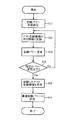
以下、図4を参照して記録の手順を説明する。
最初に、第1の記録層11に記録を行うものとして説明する。
まず、記録を行う記録層、例えば第1の記録層11へ合焦点(光スポット)を移動する(S1)。これは、中央制御回路58からサーボ制御回路56にフォーカス制御の目標(追従対象)となる記録層を指定する情報を与え、サーボ制御回路56がこれに従って対物レンズ63をディスクの記録面に垂直な方向に移動させることによりなされる。
次に、その記録層に設けられたテスト記録領域、例えばテスト記録領域21に合焦点を移動する(S2)。これは、中央制御回路58からサーボ制御回路56にシーク動作及びトラッキングの目標となるトラックを指定する情報(トラックアドレス)を与え、サーボ制御回路56がこれに従って対物レンズ63をディスクの記録面に平行な方向に移動させ、さらにはセクタアドレスに基づいて指定されたセクタを検出することによりなされる。
次にそのテスト記録領域21にテストデータを記録し、その信号を再生することにより最適記録パワーを決定する(S3)。決定された最適記録パワーを表す情報は、中央制御回路58内のデータメモリ58cに記憶される。
本願では、ステップ1からステップS3までの処理を単に「テスト記録」と言うことが
そして、その後、上記データメモリ58cに記憶された最適記録パワーを用いて当該記録層上のユーザデータ領域20にユーザデータの記録を行う(S4)。
Hereinafter, the recording procedure will be described with reference to FIG.
First, description will be made assuming that recording is performed on the
First, the focal point (light spot) is moved to a recording layer for recording, for example, the first recording layer 11 (S1). This gives the
Next, the focal point is moved to a test recording area provided in the recording layer, for example, the test recording area 21 (S2). This is because the
Next, test data is recorded in the
In the present application, the processing from step 1 to step S3 is simply referred to as “test recording”. Thereafter, the
他の記録層、即ち第2乃至第4の記録層12乃至14についてもステップS1乃至S4と同様に、テスト記録(ステップS1乃至S3)を行った後にユーザデータの記録(ステップS4)が行われる。一つの記録層へのユーザデータの記録(ステップS4)が終わる前に、他の記録層に対するテスト記録(ステップS1乃至S3)を行うようにしても良い。
例えば、第1、第2、第3、第4の記録層の順に記録を行う場合には、第1の記録層11へのユーザデータの記録が終わる前に、例えば第1の記録層11へのユーザデータの記録の合間に、第2の記録層12に対するテスト記録を行っても良い。同様に、第2の記録層12へのユーザデータの記録が終わる前に、例えば第1又は第2の記録層11又は12へのユーザデータの記録の合間に、第3の記録層13に対するテスト記録を行っても良い。同様に、第3の記録層13へのユーザデータの記録が終わる前に、例えばユーザデータの記録の合間に、第4の記録層14に対するテスト記録を行っても良い。
但し、最適記録パワーに影響を与える記録条件は時々刻々変化するので、その観点からすると、各記録層に対するテスト記録と、その記録層に対するユーザデータの記録開始までの時間は短い方が良く、各記録層に対するユーザデータの記録開始の直前に、その記録層に対するテスト記録を行うのが望ましい。
For other recording layers, that is, the second to fourth recording layers 12 to 14, user data is recorded (step S 4) after performing test recording (steps S 1 to S 3) as in steps S 1 to S 4. . Before the recording of user data on one recording layer (step S4) is completed, test recording (steps S1 to S3) on another recording layer may be performed.
For example, when recording is performed in the order of the first, second, third, and fourth recording layers, before the user data is recorded on the
However, since the recording conditions that affect the optimum recording power change from moment to moment, from that point of view, it is better that the test recording for each recording layer and the time to start recording user data for that recording layer are shorter. It is desirable to perform test recording on the recording layer immediately before the start of recording of user data on the recording layer.
第1乃至第4の記録層においてテストデータを記録するテスト記録領域は、図1及び図2を参照して説明したような配置となるように定められる。これは例えば、中央制御回路58でテストデータの記録を行う領域をトラックアドレス及びセクタアドレスで指定する際に、これらの領域が図1及び図2に示すような配置となるようにトラックアドレス及びセクタアドレスを定めることにより行われる。
Test recording areas for recording test data in the first to fourth recording layers are determined so as to be arranged as described with reference to FIGS. For example, when the
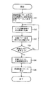
図5は、図4のステップS3の処理、即ちテスト記録領域へのテストデータの記録、再生及び最適記録パワーの決定の処理の詳細を示す。
図示のように、まず、そのテスト記録領域にテストデータを記録する(S11乃至S14)。次に、記録した信号を再生する(S15)。そして、再生した信号に基づいて最適記録パワーを決定する(S16)。
FIG. 5 shows details of the process of step S3 of FIG. 4, that is, the process of recording and reproducing test data in the test recording area and determining the optimum recording power.
As shown in the figure, first, test data is recorded in the test recording area (S11 to S14). Next, the recorded signal is reproduced (S15). Then, the optimum recording power is determined based on the reproduced signal (S16).
テスト記録領域へのテストデータの記録に当たっては、テスト記録領域に対し記録を行いながら記録パワーを段階的に変更する。例えば図6に示すように、段階的に減少させる。そのために最初に記録パワーを初期値(Pi)に設定し(S11)、テスト記録領域(テストデータを記録すべき領域)のうちの、まだテストデータが記録されていない部分(空き領域)のうちの所定の長さの部分を指定して、そこにテストデータを記録し(S12)、記録パワーを変更し、例えば所定の区分幅(決定の分解能乃至ステップ)ΔPだけ減少させる(S13)。そして、記録パワーの変更が所定回数に達していないことを確認して(S15),ステップS12に戻り、変更後の記録パワーでテスト記録領域のうちの空き領域のうちの所定の長さの部分を再び指定して、そこにテストデータを記録する(S12)。記録パワーの変更が所定回数に達したときは(S14)、ステップS15に進む。ステップS12における空き領域のうちの所定の長さの部分の指定は、空き領域に属するセクタのアドレスを指定することにより行われる。 When recording test data in the test recording area, the recording power is changed stepwise while recording in the test recording area. For example, as shown in FIG. For this purpose, first, the recording power is set to the initial value (Pi) (S11), and the portion of the test recording area (the area where the test data is to be recorded) where the test data is not yet recorded (the empty area) The test data is recorded there (S12), the recording power is changed, and for example, a predetermined section width (determination resolution or step) ΔP is decreased (S13). Then, it is confirmed that the recording power change has not reached the predetermined number of times (S15), the process returns to step S12, and the recording power after the change is a part of the predetermined length in the empty area of the test recording area. Is designated again, and test data is recorded there (S12). When the recording power change has reached the predetermined number of times (S14), the process proceeds to step S15. The designation of a predetermined length portion of the free area in step S12 is performed by designating the address of a sector belonging to the free area.
なお、ステップS14では、記録パワーの変更が所定回数に達したかどうかの判定を行う代わりに、記録パワーが所定値に達した(所定の最終値まで下がった)かどうかの判定を行うこととしても良い。 In step S14, instead of determining whether or not the recording power change has reached a predetermined number of times, it is determined whether or not the recording power has reached a predetermined value (decreased to a predetermined final value). Also good.
上記の段階的記録パワーの段階的変更の初期値は、ディスクの製造上のバラツキや記録条件(温度など)の如何を問わず、最適記録パワーが存在し得ると考えられる範囲(最大範囲)R1の上限(最大値)Pomaxであり、記録パワーの段階的変更の最終値は上記最大範囲の下限(最小値)Pominである。 The initial value of the gradual change of the gradual recording power is a range (maximum range) R1 in which the optimum recording power can be present regardless of disc manufacturing variations and recording conditions (temperature, etc.). The final value of the stepwise change in recording power is the lower limit (minimum value) Pomin of the maximum range.
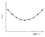
ステップS15では、記録されたテストデータを再生し、図7に示したように記録パワーと再生信号品質(例えばジッタ)の関係を求め、最も再生信号品質が良くなる記録パワー(ジッタの場合には、ジッタが最小になる記録パワー)を最適記録パワーとして求める(S16)。 In step S15, the recorded test data is reproduced, the relationship between the recording power and the reproduction signal quality (for example, jitter) is obtained as shown in FIG. 7, and the recording power (in the case of jitter is the best) for the reproduction signal quality. The recording power that minimizes jitter) is obtained as the optimum recording power (S16).
記録パワーとジッタとの関係を求める代わりに、記録パワーと再生信号振幅の関係に基づいて最適の記録パワーを求めても良い。実際の光ディスク装置においてはテスト記録領域の容量が限られていることや、最適記録パワーとジッタの関係を求めるには、時間を要するためである。さらに、記録パワーとアシンメトリ値との関係に基づいて、最適記録パワーを求めても良い。このような場合には、図3のジッタ検出回路68の代わりに、再生信号振幅検出回路、アシンメトリ値検出回路を設ける。
Instead of obtaining the relationship between the recording power and the jitter, the optimum recording power may be obtained based on the relationship between the recording power and the reproduction signal amplitude. This is because in an actual optical disc apparatus, the capacity of the test recording area is limited and it takes time to obtain the relationship between the optimum recording power and jitter. Furthermore, the optimum recording power may be obtained based on the relationship between the recording power and the asymmetry value. In such a case, a reproduction signal amplitude detection circuit and an asymmetry value detection circuit are provided instead of the
本実施の形態では、上記のように、隣接した記録層間では、テスト記録領域が互いにディスクの厚さ方向に重ならないように配置している。その理由は以下の通りである。即ち、テスト記録領域においては記録パワーが最適値と想定される値よりも小さい値から大きい値まで変化させて記録を行うため、高記録パワーでの記録も行われる。その記録パワーは光ディスク装置に依存して自由に決定され、規定することも困難であるため、テスト記録領域に対向する領域、即ち隣接する記録層の厚さ方向に互いに整列した領域に影響を及ぼす可能性が高い。そこで、このような影響を避けるため、隣接する記録層間では、テスト記録領域が互いに厚さ方向に重ならないようにした。
例えば、図8に示すように、例えば第3の記録層13に対して記録パワーを照射する際に、手前側、即ち光ピックアップ52の設けられた側にある第2の記録層12に対してもある程度の記録パワーが与えられることとなる。その影響の度合い記録層間の間隔により異なり、間隔が大きいほど光スポット径が大きくなり、エネルギー密度が小さくなり、受ける影響も小さくなるが、隣接する記録層(第2の記録層12)ではエネルギー密度もかなり大きく影響を無視できない。
In the present embodiment, as described above, the test recording areas are arranged so as not to overlap each other in the thickness direction of the disk between adjacent recording layers. The reason is as follows. That is, in the test recording area, recording is performed by changing the recording power from a value smaller than a value that is assumed to be the optimum value to a larger value, so that recording with a high recording power is also performed. Since the recording power is freely determined depending on the optical disk device and is difficult to define, it affects the area facing the test recording area, that is, the area aligned with each other in the thickness direction of the adjacent recording layer. Probability is high. Therefore, in order to avoid such influence, the test recording areas are not overlapped in the thickness direction between adjacent recording layers.
For example, as shown in FIG. 8, when the recording power is irradiated to the
一方、間に別の記録層が介在している記録層相互間、例えば第1の記録層11と第3の記録層13の間では、テスト記録領域同士が互いに厚さ方向に整列するようにしているが、その理由は以下の通りである。
まず、間に別の記録層が介在している記録層間では、上記のような、1つの記録層に記録を行うときの他の記録層への影響が小さい。例えば、図8において、合焦位置にある第3の記録層13から、隣接する第2の記録層12で隔てられた第1の記録層11への影響は、第2の記録層12への影響に比べて格段に小さく、無視できる程度である。これは、影響の度合いは、記録層間の距離の二乗に比例して低下するからである。
On the other hand, between the recording layers in which another recording layer is interposed, for example, between the
First, in the recording layer in which another recording layer is interposed, the influence on the other recording layer when recording on one recording layer as described above is small. For example, in FIG. 8, the influence on the
また、熱の拡散路を考慮しても、記録層は金属膜や色素等の比較的熱伝導率が大きい材料で構成されており、図8に矢印D1乃至D4で示すようにそれぞれの記録層に沿った熱拡散があり、そのうち、合焦位置にある第3の記録層13における熱拡散D3、それに隣接する第2及び第4の記録層12、14における熱拡散D2、D4のため、第1の記録層11に達する熱はかなり小さくなる。
Even when the heat diffusion path is taken into consideration, the recording layer is made of a material having a relatively high thermal conductivity such as a metal film or a dye, and each recording layer is shown by arrows D1 to D4 in FIG. Among them, the thermal diffusion D3 in the
3層以上の記録可能光ディスクにおいてはすべての記録層の記録領域が互いに重なり合わないようにすることも考えられるが、それには以下の問題がある。例えば第3の記録層13のテスト記録領域23の配置方法として、テスト記録領域23を第1の記録層11のテスト記録領域21及び第2の記録層12のテスト記録領域22の双方と重ならない更に異なる位置に配置する場合には、それらのテスト記録領域に対向する領域が増え、このような対向領域は通常のユーザデータの記録には適さないので、記録領域の利用効率が下がる。
また、例えば、再生専用領域とテスト記録領域とが対向するような配置にする場合などには、各記録層のディスク構造(再生専用領域の配置)が記録層ごとに異なることになり、ディスクの製造工程が複雑となる。さらにテスト記録やユーザデータの記録を行う場合のアドレス指定のための記録再生装置のプログラムが複雑となる。
In a recordable optical disc having three or more layers, it can be considered that the recording areas of all the recording layers do not overlap each other, but this has the following problems. For example, as a method for arranging the
In addition, for example, when the read-only area and the test recording area are arranged to face each other, the disk structure of each recording layer (arrangement of the read-only area) differs for each recording layer. The manufacturing process becomes complicated. Furthermore, the program of the recording / reproducing apparatus for address designation when performing test recording or user data recording becomes complicated.
それに対して、本実施の形態においては、例えば第3の記録層13のテスト記録領域23が第1の記録層11のテスト記録領域21と厚さ方向に整列した位置に配置されており、第3のテスト記録領域23に対応した位置に新たに対向領域を追加する必要がない。また、第3の記録層13内部の配置は第1の記録層11と同様とすることが可能で、ディスクの製造工程や記録再生装置のプログラムが簡単となる。
On the other hand, in the present embodiment, for example, the
また、第4の記録層14のテスト記録領域24が第2の記録層12のテスト記録領域22と厚さ方向に整列した位置に配置されており、第4のテスト記録領域24に対応した位置に新たに対向領域を追加する必要がない。また、第4の記録層14内部の配置は第2の記録層12と同様とすることが可能で、ディスクの製造工程や記録再生装置のプログラムが簡単となる。
Further, the
本実施の形態1では記録層が4層ある場合について示したが、3層や5層以上の記録層を有するディスクの場合も同様に、奇数層のテスト記録領域を互いに厚さ方向に整列した位置に形成し、偶数層のテスト記録領域を互いに厚さ方向に整列した位置に形成すれば良い。 In the first embodiment, the case where there are four recording layers has been described. Similarly, in the case of a disc having three or more recording layers, the test recording areas of odd layers are aligned in the thickness direction. The test recording areas of even layers may be formed at positions aligned in the thickness direction.
さらに、上記のように、非記録領域31乃至34とテスト記録領域11乃至14とが互いに対向するようにテスト記録領域11乃至14の位置を定めることにより以下の効果が得られる。即ち、互いに隣接する層間で、テスト記録領域と重なり合うと、テスト記録領域と対向する領域が、テスト記録の影響を受けて、後にその領域にテスト記録を行う際、正しいテスト記録が行えなくなる可能性がある。そこで、記録パワーの影響を受けない非記録領域、例えば再生専用領域等がテスト記録領域に対向するような配置にすることにより上記の問題を解決することができる。
Further, as described above, the following effects can be obtained by determining the positions of the
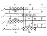
なお、上記の例では、再生専用領域が、テスト記録領域の対向領域に一致しているが、再生専用領域がテスト記録領域に対向する領域以外の領域をも占めるように構成されていても良い。そのような構造の一例を図9及び図10に示す。図9は、図1と同様の、ただし、ディスクの中心部を拡大して示す平面図、図10は、図2と同様の、図9のX−X線に沿う概略断面図である。 In the above example, the read-only area coincides with the area facing the test recording area, but the read-only area may also occupy an area other than the area facing the test recording area. . An example of such a structure is shown in FIGS. 9 is a plan view similar to FIG. 1 except that the center of the disk is enlarged, and FIG. 10 is a schematic cross-sectional view taken along the line XX of FIG.
図9及び図10の光ディスクは、図1及び図2の光ディスクと同様である。しかし、奇数番目の記録層11,13の再生専用領域41、43が互いに厚さ方向に整列した位置に形成され、偶数番目の記録層12、14の再生専用領域42、44が互いに厚さ方向に整列した位置に形成され、奇数番目の記録層11、13における再生専用領域41、43の一部41a、43aと偶数番目の記録層における再生専用領域42、44の少なくとも一部42a、44aとが光ディスクの厚さ方向に互いに重ならないように形成されている。
そして、奇数番目の記録層11、13における再生専用領域41、43のうちの上記一部41a、43aの一部41b、43bに対向する位置に、偶数番目の記録層12、14におけるテスト記録領域22、24が形成され、偶数番目の記録層12、14における再生専用領域42、44のうちの上記一部42a、44aの一部42b、44bに対向する位置に、奇数番目の記録層11、13におけるテスト記録領域21、23が形成されている。
なお、奇数番目の記録層11、13における再生専用領域41、43のうちの上記一部41a、43aの全体に対向する位置に、偶数番目の記録層12、14におけるテスト記録領域22、24が形成され、偶数番目の記録層12、14における再生専用領域42、44のうちの上記一部42a、44aの全体に対向する位置に、奇数番目の記録層11、13におけるテスト記録領域21、23が形成されるようにしても良い。
The optical discs in FIGS. 9 and 10 are the same as the optical discs in FIGS. However, the read-
Then, the test recording areas in the even-numbered recording layers 12 and 14 are located at positions facing the
Note that the
図9及び図10に示される光ディスクを形成するには、最初に図9及び図10に示すように、再生専用領域41乃至44が形成された光ディスクを用意する。次に、それぞれの記録層に対し、上記したような手順でテスト記録を行うことにより、それぞれの記録層にテスト記録領域21乃至24を、図9及び図10に示す位置に形成する。
In order to form the optical disk shown in FIGS. 9 and 10, first, as shown in FIGS. 9 and 10, an optical disk having read-
なおまた、図1及び図2に示した例では、テスト記録領域21乃至24に対向する非記録領域31乃至34が再生専用領域であるが、再生専用領域以外の非記録領域としても良い。テスト領域に対向する領域が再生専用領域であると、テスト記録領域への記録や再生が、再生専用領域のピットの影響を受けるおそれがあるが、再生専用領域をテスト領域に対向する領域以外の領域に配置し、テスト領域に対向する領域を、再生専用領域以外の非記録領域とすることでそのような問題を解決することができる。そのような記録領域の配置の一例を、図11及び図12に示す。図11は、図1と同様の平面図、図12は、図2と同様の、図11のXII−XII線に沿う概略断面図である。
In the example shown in FIGS. 1 and 2, the
図11及び図12の光ディスクは、図1及び図2の光ディスクと同様である。しかし、テスト記録領域21乃至24に対向する領域31乃至34が再生専用領域以外の非記録領域であり、テスト記録領域21乃至24及び対向領域31乃至34の外側で、これらに隣接した位置に再生専用領域41乃至44が形成されている。
The optical discs in FIGS. 11 and 12 are the same as the optical discs in FIGS. However, the
図9及び図10の光ディスクや、図11及び図12の光ディスクの場合、記録装置は、各記録層(11乃至14のいずれか)のテスト記録に先立って、同じ記録層の再生専用領域(41乃至44のいずれか)から記録条件などを読み出し、その後で、光ピックアップの合焦点をテスト領域に移して、テスト記録を行う。その際、再生専用領域から読み出された記録条件などにより、テスト記録のための記録条件、少なくともその初期値を設定する。
上記のように、記録条件などを記録した再生専用領域がテスト記録領域に隣接ないし近接している配置とすれば、記録条件などを読み出す処理を行った後テストデータを記録領域までの合焦点の移動が少なくて済み、テスト記録に要する時間が短くて済むと言う利点がある。
In the case of the optical discs shown in FIGS. 9 and 10 and the optical discs shown in FIGS. 11 and 12, the recording apparatus performs the read-only area (41) of the same recording layer prior to the test recording of each recording layer (any one of 11 to 14). The recording conditions are read out from any one of (44) to 44), and then the focal point of the optical pickup is moved to the test area to perform test recording. At that time, the recording condition for test recording, at least its initial value, is set according to the recording condition read from the read-only area.
As described above, if the read-only area in which the recording conditions and the like are recorded is arranged adjacent to or close to the test recording area, the test data is recorded at the focal point up to the recording area after performing the process of reading the recording conditions and the like. There is an advantage that less movement is required and the time required for test recording is short.
実施の形態2.
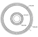
図13はこの発明の実施の形態2の記録方法で記録された光ディスクを示す概略平面図である。図13に示す光ディスク2は、図1及び図2の光ディスク1と同様に、記録層が4層、即ち表面に近い側から順に第1、第2、第3、第4の記録層11、12、13、14が形成されている。第1乃至第4の記録層11、12、13、14には、それぞれの記録層に対する最適記録パワーを決定するためのテスト記録領域21、22、23、24が設けられている。
Embodiment 2. FIG.
FIG. 13 is a schematic plan view showing an optical disk recorded by the recording method according to Embodiment 2 of the present invention. The optical disc 2 shown in FIG. 13 has four recording layers, that is, the first, second, third, and fourth recording layers 11 and 12 in order from the side closer to the surface, similarly to the optical disc 1 of FIGS. , 13 and 14 are formed. The first to fourth recording layers 11, 12, 13, and 14 are provided with
実施の形態1においては、奇数層と偶数層のテスト記録領域を共に光ディスク1の最内周付近、即ち最内周縁1aの近傍に配置していたが、実施の形態2においては、奇数層11、13のテスト領域21、23が最内周付近、即ち最内周縁1aの近傍に位置するのに対して偶数層12、14のテスト領域22、24が最外周付近、即ち最外周縁1bの近傍に配置されている。
In the first embodiment, the odd-numbered and even-numbered test recording areas are both arranged in the vicinity of the innermost periphery of the optical disc 1, that is, in the vicinity of the innermost peripheral edge 1a. , 13 are located in the vicinity of the innermost periphery, that is, in the vicinity of the innermost peripheral edge 1a, whereas the
このような配置とした場合の利点は以下の通りである。即ち、例えば第1の記録層11では、テスト記録領域21を最内周付近に形成することしているので、第1の記録層11の記録は最内周側から始まり、最内周付近のテスト記録領域でテスト記録を行い、その後、内周側から外周側に向かう順序でユーザデータの記録を行い、最外周側に達したときに第1の記録層11の記録が終わる。
なお、内周側でのテスト記録に当たり、事前にその外側であって隣接する位置にある再生専用領域に合焦点を移して記録条件情報などを読みこんだりするため、合焦点が若干内側に向かって移動したりするが、これは小さな(径方向の移動量が少ない)動きであり、このような動きがあったとしても、全体としては「内周側から外周側へ記録が進む」に該当すると言える。
次に第2の記録層12の記録を開始するには、合焦点を第1の記録層11から第2の記録層12に移動させる必要がある。このとき、第2の記録層12のテスト記録領域22を最内周付近に形成する場合には、合焦点を最外周側から最内周付近に移動させる必要があり、そのためのアクセス時間が掛かる。一方、本実施の形態のように、テスト記録領域22を最外周付近に形成する場合には、そのような第2の記録層12上での移動(テスト記録領域22に到達するまでの移動)の必要がなく、第1の記録層11の記録が終わった時点で最外周側にある合焦点を第1の記録層11から第2の記録層に移動させ、最外周側のテスト記録領域21でテスト記録を行って、その後最外周側から内周側に向かう順序でユーザデータの記録を行えば良い。従って、テスト記録のための時間を短縮することができる。
同様に、第2の記録層12の記録(テスト記録、及びユーザデータの記録)を全て完了し、合焦点がディスクの最内周側にあるとき、合焦点を第2の記録層12から第3の記録層13に移動させ、第3の記録層13への記録を始める場合、テスト記録領域23を最内周付近に形成することとするので、第3の記録層13上での移動の必要がなくなり、テスト記録のための時間を短縮することができる。
同様に、第3の記録層13の記録(テスト記録、及びユーザデータの記録)を全て完了し、合焦点がディスクの最外周側にあるとき、合焦点を第3の記録層13から第4の記録層14に移動させ、第4の記録層14への記録を始める場合、テスト記録領域24を最外周付近に形成することとするので、第4の記録層14上での移動の必要がなくなり、テスト記録のための時間を短縮することができる。
このように第1及び第3の記録層11、13、即ち奇数層のテスト記録領域21、23を最内周付近に形成し、第2及び第4の記録層、即ち偶数層のテスト記録領域22、24を最外周付近に形成することでテスト記録のための時間を短縮することができる。
The advantages of such an arrangement are as follows. That is, for example, in the
In addition, when performing test recording on the inner circumference side, the focus is shifted inward slightly in order to read the recording condition information and the like by moving the focus to a read-only area located outside and adjacent to it in advance. However, this is a small movement (with a small amount of movement in the radial direction), and even if there is such a movement, the whole corresponds to “recording advances from the inner circumference side to the outer circumference side”. I can say that.
Next, in order to start recording on the
Similarly, when all recording (test recording and user data recording) of the
Similarly, when all the recording (test recording and user data recording) of the
Thus, the first and third recording layers 11 and 13, that is, the odd-numbered
なお、上記のようにする代わりに、第1及び第3の記録層11、13、即ち奇数層のテスト記録領域21、23を最外周付近に形成し、第2及び第4の記録層、即ち偶数層のテスト記録領域22、24を最内周付近に形成することとしても良く、その場合も同様の効果が得られる。
Instead of the above, the first and third recording layers 11 and 13, that is, odd-numbered
各記録領域を利用してテスト記録を行う手順や、各記録層に対応して最適記録パワーを決定する手順は実施の形態1と同様である。 The procedure for performing test recording using each recording area and the procedure for determining the optimum recording power corresponding to each recording layer are the same as in the first embodiment.
実施の形態3.
図14はこの発明の実施の形態3の記録方法で記録された光ディスクを示す概略平面図である。図14に示す光ディスク2は、図1及び図2の光ディスク1や、図13の光ディスクと同様に、記録層が4層、即ち表面に近い側から順に第1、第2、第3、第4の記録層11、12、13、14が形成されている。図1及び図2の光ディスク1や図13の光ディスク2と異なるのは、各層においてテスト記録領域が最内周付近、即ち最内周縁1aの近傍と最外周付近、即ち最外周縁1bの近傍の双方に配置されていることである。具体的には、第1の記録層11は最内周付近にテスト記録領域21Aを有するとともに、最外周付近にテスト記録領域21Bを有する。同様に、第2、第3、第4の記録層12、13、14はそれぞれ最内周付近にテスト記録領域22A、23A、24Aを有するとともに、最外周付近にテスト記録領域22B、23B、24Bを有する。
Embodiment 3 FIG.
FIG. 14 is a schematic plan view showing an optical disk recorded by the recording method according to Embodiment 3 of the present invention. The optical disk 2 shown in FIG. 14 has four recording layers, that is, the first, second, third, and fourth layers in order from the side closer to the surface, like the optical disk 1 of FIGS. 1 and 2 and the optical disk of FIG. Recording layers 11, 12, 13, and 14 are formed. 1 and FIG. 2 and the optical disc 2 of FIG. 13 are different from each other in that each layer has a test recording area in the vicinity of the innermost periphery, that is, in the vicinity of the innermost periphery 1a and in the vicinity of the outermost periphery, that is, in the vicinity of the
このように各層において、最内周付近と最外周付近の双方にテスト記録領域を設けることの利点は以下の通りである。即ち、ディスクの記録を高速で行う場合、同じ線速度を得るためには最内周では最外周の倍近い回転数でディスクを回転させる必要があり、ディスクモータの使用限界を超える場合が多い。また、ディスクの記録を高速で行う場合、内周側と外周側とでは条件がかなり異なるため、最内周付近のテスト記録領域でテスト記録を行うことにより求められた最適記録パワーを外周側でのユーザデータの記録に用いると適切でない場合がある。また、最外周付近のテスト記録領域でテスト記録を行うことにより求められた最適記録パワーを内周側でのユーザデータの記録に用いると適切でない場合がある。そこで、図14に示すように、最内周付近と最外周付近の双方にテスト記録領域を設け、最内周付近のテスト記録領域でテスト記録を行うことにより求められた最適記録パワーと最外周付近のテスト記録領域でテスト記録を行うことにより求められた最適記録パワーの双方を用い、さらにユーザデータが記録される径方向上の位置に基づいて、その記録位置における最適記録パワーを決定することで、上記の問題を解決することができる。例えば、最内周付近のテスト記録領域でテスト記録を行うことにより求められた最適記録パワーを、内周側、即ち所定の径方向上の位置、例えば中間位置よりも内周側でのユーザデータの記録に利用し、最外周付近のテスト記録領域でテスト記録を行うことにより求められた最適記録パワーを外周側、即ち所定の径方向上の位置、例えば中間位置よりも外周側でのユーザデータの記録に利用することとする。或いは、ユーザデータの記録位置(半径方向上の位置)に応じて、最内周付近のテスト記録領域でテスト記録を行うことにより求められた最適記録パワーと最外周付近のテスト記録領域でテスト記録を行うことにより求められた最適記録パワーを加重平均することにより得られた記録パワーを用いてその記録位置におけるユーザデータの記録を行うこととしても良い。 As described above, in each layer, the advantages of providing the test recording areas near both the innermost periphery and the outermost periphery are as follows. That is, when recording a disk at a high speed, in order to obtain the same linear velocity, it is necessary to rotate the disk at the innermost circumference at a rotational speed close to twice the outermost circumference, which often exceeds the use limit of the disk motor. Also, when performing disc recording at high speed, the conditions on the inner and outer circumference sides are quite different, so the optimum recording power obtained by performing test recording in the test recording area near the innermost circumference is on the outer circumference side. If it is used for recording user data, it may not be appropriate. Moreover, it may not be appropriate to use the optimum recording power obtained by performing test recording in the test recording area near the outermost periphery for recording user data on the inner periphery. Therefore, as shown in FIG. 14, the optimum recording power and the outermost circumference obtained by providing test recording areas near both the innermost circumference and the outermost circumference, and performing test recording in the test recording area near the innermost circumference. Using both the optimum recording power obtained by performing test recording in a nearby test recording area, and determining the optimum recording power at that recording position based on the radial position where user data is recorded Thus, the above problem can be solved. For example, the optimum recording power obtained by performing the test recording in the test recording area near the innermost circumference is set to the user data on the inner circumference side, that is, a position in a predetermined radial direction, for example, the inner circumference side from the intermediate position. The optimum recording power obtained by performing test recording in the test recording area near the outermost periphery is used for recording of the user data on the outer peripheral side, that is, at a position in a predetermined radial direction, for example, on the outer peripheral side from the intermediate position. It will be used for recording. Alternatively, the optimum recording power obtained by performing the test recording in the test recording area near the innermost circumference and the test recording in the test recording area near the outermost circumference according to the user data recording position (position in the radial direction). The user data may be recorded at the recording position by using the recording power obtained by weighted averaging the optimum recording power obtained by performing the above.
実施の形態4.
上記の実施の形態1に関連して、テスト記録の手順について説明したが、実施の形態1のような手順の代わりに、以下のような異なる手順でテスト記録を行うことができる。
即ち、実施の形態1では、各層に対するテスト記録を一連の動作で行い、また、テストデータの記録における記録パワーの変更(図5のステップS13)における区分幅を、最適記録パワーを十分な精度で行うのに必要な値に設定しているが、上記の処理を複数の段階に分けて行っても良い。
Embodiment 4 FIG.
Although the test recording procedure has been described in relation to the first embodiment, the test recording can be performed by the following different procedure instead of the procedure as in the first embodiment.
That is, in the first embodiment, test recording for each layer is performed by a series of operations, and the segment width in changing the recording power in recording the test data (step S13 in FIG. 5) is set to the optimum recording power with sufficient accuracy. Although it is set to a value necessary for performing, the above processing may be performed in a plurality of stages.
以下に、2段階に分けて行う場合について説明する。この場合、最初の段階はいわば粗調整であり、テスト記録領域に、第1の所定の区分幅ずつ互いに異なる複数の値の記録パワーでテストデータの記録を行ない、記録されたテストデータを再生し、再生結果を評価することにより最適記録パワーの概略値を求める。第2の段階は、いわば微調整であり、テスト記録領域に、上記第1の所定の区分幅よりも小さい第2の所定幅ずつ互いに異なり、かつ上記最適記録パワーの概略値に近い範囲内の、複数の値の記録パワーでテストデータの記録を行ない、記録されたテストデータを再生し、再生結果を評価することにより、上記最適記録パワーのより正確な値を求める。
例えば、粗調整においては、ディスクの製造パラツキや記録条件(温度など)の如何を問わず、最適記録パワーが存在し得ると考えられる範囲(最大範囲)の全体に亘って比較的大きな区分幅(ステップ)を用いて記録パワーを変化させ、用いられている記録条件下で用いられているディスクの個々の層に関して最適記録パワーの概略値に近い範囲、即ち最適記録パワーが含まれると判断される範囲を求める。微調整においては、上記の最適記録パワーが含まれると判断される範囲中で比較的小さな区分幅(ステップ)を用いて記録パワーを変化させ、最適記録パワーを求める。
Hereinafter, a case where the process is performed in two stages will be described. In this case, the first stage is so-called coarse adjustment, and test data is recorded in the test recording area with recording powers of a plurality of values different from each other by the first predetermined section width, and the recorded test data is reproduced. The approximate value of the optimum recording power is obtained by evaluating the reproduction result. The second stage is so-called fine adjustment, and the test recording area is different from each other by a second predetermined width smaller than the first predetermined segment width and is within a range close to the approximate value of the optimum recording power. The test data is recorded with a plurality of values of recording power, the recorded test data is reproduced, and the reproduction result is evaluated to obtain a more accurate value of the optimum recording power.
For example, in coarse adjustment, a relatively large segment width (maximum range) over which the optimum recording power can be present (maximum range) regardless of disc manufacturing variation and recording conditions (temperature, etc.) Step) is used to change the recording power, and it is determined that the optimum recording power is included in the range close to the approximate value of the optimum recording power for each layer of the disc used under the recording conditions used. Find the range. In the fine adjustment, the optimum recording power is obtained by changing the recording power using a relatively small section width (step) within the range where the optimum recording power is determined to be included.
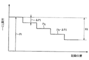
例えば、粗調整においては、上記の最大範囲R1にわたり、図15及び図16に示すように、比較的大きいステップΔP1で記録パワーを段階的に変更して記録パワーPqと記録パワー(Pq−ΔP1)までの範囲に最適値Poが含まれるとの判断をする。微調整においては、図17及び図18に示すように、記録パワーPqから記録パワー(Pq−ΔP1)までの範囲において、ステップΔP1より小さなステップΔP2で記録パワーを段階的に変更して、最適値Poを求める。 For example, in coarse adjustment, as shown in FIGS. 15 and 16, over the maximum range R1, the recording power is changed stepwise in a relatively large step ΔP1, and the recording power Pq and the recording power (Pq−ΔP1) It is determined that the optimum value Po is included in the range up to. In the fine adjustment, as shown in FIGS. 17 and 18, the recording power is changed stepwise at a step ΔP2 smaller than the step ΔP1 in the range from the recording power Pq to the recording power (Pq−ΔP1), and the optimum value is obtained. Find Po.
上記のこれらの処理をフローチャートで表せば図19及び図20のごとくである。このうち、粗調整を示す図19の処理は、概して図5と同じであり、ステップS21乃至S27がそれぞれステップS11乃至S17に対応するが、ステップS23における記録パワーの変更における区分幅(ステップ)がステップS13の区分幅よりも大きい。また、ステップS26においては、ステップS16のような最適記録パワーの決定が行われるのではなく、「最適記録パワーが含まれる範囲を求める」という処理が行われる。 These processes described above are represented by flowcharts as shown in FIGS. Among these, the process of FIG. 19 showing the rough adjustment is generally the same as FIG. 5 and steps S21 to S27 correspond to steps S11 to S17, respectively, but the segment width (step) in the change of the recording power in step S23 is the same. It is larger than the segment width in step S13. In step S26, the optimum recording power is not determined as in step S16, but a process of “determining a range including the optimum recording power” is performed.
微調整を示す図20の処理は、概して図5と同じであり、ステップS31乃至S37がそれぞれステップS11乃至S17に対応するが、ステップS31の記録パワー初期設定における初期値が、ステップS26で求められた範囲の上限に設定される。また、ステップS34の所定のパワー変更が完了したかどうかの判定ステップにおいては、記録パワーがステップS26で求められた範囲の下限に達したかどうかの判定が行われる。 The process of FIG. 20 showing fine adjustment is generally the same as that of FIG. 5, and steps S31 to S37 correspond to steps S11 to S17, respectively, but the initial value in the recording power initial setting of step S31 is obtained in step S26. Set to the upper limit of the range. Further, in the step of determining whether or not the predetermined power change in step S34 is completed, it is determined whether or not the recording power has reached the lower limit of the range obtained in step S26.
また、上記のように2段階に分ける場合、粗調整が終わったら、直ちに微調整を行うこととしても良く、粗調整の後、別の処理を行い、その後微調整を行っても良い。
例えば、ディスクが複数の記録層、例えば2つの記録層を有し、その内の一つの記録層(第1の記録層)にユーザデータの記録を行い、その後他の記録層(第2の記録層)に対するユーザデータの記録を行う場合、第1の記録層におけるユーザデータの記録の開始前に、第1の記録層に対するテスト記録と、第2の記録層に対するテスト記録のうちの上記した第1の段階(粗調整)を行ない、第1の記録層に対するユーザデータの記録が終わってから第2の記録層に対するユーザデータの記録の開始前に上記した第2の段階の処理(微調整)を行うこととしても良い。
Further, in the case of dividing into two stages as described above, fine adjustment may be performed immediately after the coarse adjustment is completed, or another process may be performed after the coarse adjustment, and then the fine adjustment may be performed.
For example, a disc has a plurality of recording layers, for example, two recording layers, and user data is recorded on one of the recording layers (first recording layer), and then the other recording layer (second recording layer). When the user data is recorded on the first recording layer, before the start of the recording of the user data on the first recording layer, the above-mentioned first of the test recording on the first recording layer and the test recording on the second recording layer are performed. Step 1 (coarse adjustment) is performed, and after the user data is recorded on the first recording layer, the above-described second step processing (fine adjustment) is started before the start of user data recording on the second recording layer. It is also good to do.
第1の記録層と第2の記録層に跨って連続記録を行う場合などには、第1の記録層に対するユーザデータの記録が終わってから第2の記録層に対するユーザデータの記録の開始までの時間は短いことが望まれ、一方、記録条件(温度など)は時々刻々変化するので、微調整は各記録層に対するユーザデータの記録の開始直前に行うことが望ましいが、上記の手順とすることで、上記の二つの要求に応えることができる。 When performing continuous recording across the first recording layer and the second recording layer, etc., from the end of user data recording to the first recording layer to the start of user data recording to the second recording layer However, since the recording conditions (temperature, etc.) change from moment to moment, fine adjustment is preferably performed immediately before the start of user data recording on each recording layer. Thus, the above two requirements can be met.
上記の手順において、第2の記録層に対する第1段階の処理(粗調整)を、第1の記録層に対するテスト記録の前に行っても良く、第1の記録層に対するテスト記録の後に行っても良い。また、第1の記録層に対するテスト記録を、2段階に分けて行っても良く、図5を参照して説明したように1段階で行っても良い。
さらにまた、第1の記録層に対するユーザデータの記録が途中で中断される場合であって、その中断時間が第2の記録層に対するテスト記録の第1段階の処理(粗調整)を行うのに十分な長さを有する場合、その中断時間中に第2の記録層に対する粗調整を行うこととしても良い。要するに、第1の記録層に対するユーザデータの記録の終了の前に第2の記録層に対する粗調整を行っておけば、第1の記録層へのユーザデータの記録の終了と第2の記録層へのユーザデータの記録の開始前には第2の記録層に対する微調整のみを行えば良いので、時間を短縮することができる。
In the above procedure, the first stage processing (coarse adjustment) for the second recording layer may be performed before the test recording for the first recording layer, or after the test recording for the first recording layer. Also good. Further, the test recording for the first recording layer may be performed in two stages, or may be performed in one stage as described with reference to FIG.
Furthermore, the recording of user data on the first recording layer is interrupted halfway, and the interruption time is used to perform the first stage processing (coarse adjustment) of the test recording on the second recording layer. If the length is sufficient, rough adjustment may be performed on the second recording layer during the interruption time. In short, if the rough adjustment is performed on the second recording layer before the end of the recording of the user data on the first recording layer, the end of the recording of the user data on the first recording layer and the second recording layer are performed. Since it is only necessary to make fine adjustments to the second recording layer before starting the recording of user data on the recording medium, the time can be shortened.
実施の形態5.
実施の形態1では、各記録層に対するユーザデータの記録に先立って、当該記録層に対するテスト記録を行っているが、このようにする代わりに、複数の記録層、例えばディスクのすべての記録層に対してテスト記録(S1乃至S3)を行った後、それらの記録層に対するユーザデータの記録(S4)を開始することとしても良い。
この場合、一つの記録層にテストデータを記録し(図5のステップS11ないしS14)、再生して(S15)、最適記録パワーを決定(S16)した後、別の記録層へのテストデータの記録(S11乃至S14)を行っても良く、複数の記録層にテストデータの記録(S11乃至S14)を行った後、それらの複数の記録層から順にテストデータを再生し(S15)、それぞれの記録層のための最適記録パワーの決定(S16)を行うようにしても良い。
Embodiment 5 FIG.
In the first embodiment, prior to recording user data on each recording layer, test recording on the recording layer is performed. Instead of doing this, a plurality of recording layers, for example, all recording layers of a disc are recorded. On the other hand, after performing test recording (S1 to S3), user data recording (S4) on those recording layers may be started.
In this case, test data is recorded on one recording layer (steps S11 to S14 in FIG. 5), reproduced (S15), the optimum recording power is determined (S16), and then the test data is transferred to another recording layer. Recording (S11 to S14) may be performed. After recording test data on a plurality of recording layers (S11 to S14), test data is reproduced in order from the plurality of recording layers (S15). The optimum recording power for the recording layer may be determined (S16).
このように複数の記録層に対してテスト記録を行った後、それらの記録層に対するユーザデータの記録を開始することとすれば、一つの記録層(第1の記録層)と別の記録層(第2の記録層)に跨って連続記録を行う場合などには、第1の記録層に対するユーザデータの記録が終わった後、(テスト記録を行う必要がないので、)直ちに第2の記録層に対するユーザデータの記録を開始することができるという利点がある。 If test recording is performed on a plurality of recording layers in this manner and then recording of user data on these recording layers is started, one recording layer (first recording layer) and another recording layer are recorded. In the case where continuous recording is performed across the (second recording layer), the second recording is immediately performed after the recording of user data on the first recording layer is completed (since it is not necessary to perform test recording). There is an advantage that recording of user data to the layer can be started.
各記録層に対するユーザデータの記録に先立って当該記録層に対するテスト記録を行うか、上記のように複数の記録層に対するユーザデータの記録に先立って当該複数の記録層のすべてに対するテスト記録を行うかを選択可能にすることもできる。例えば、記録装置に選択のための操作入力手段を設けておき、ユーザが操作入力手段の操作により選択するように構成することができる。ユーザは例えば複数の記録層に跨ると判断される記録を行う場合には、操作入力手段を操作して、複数の記録層に対するテスト記録を行わせる。 Whether test recording is performed on the recording layer prior to recording user data on each recording layer, or test recording is performed on all of the plurality of recording layers prior to recording user data on the plurality of recording layers as described above. Can also be made selectable. For example, an operation input unit for selection may be provided in the recording apparatus so that the user can select by operating the operation input unit. For example, when performing recording that is determined to extend over a plurality of recording layers, the user operates the operation input unit to perform test recording on the plurality of recording layers.
なお、上記のように複数の記録層に対するユーザデータの記録に先立って当該複数の記録層のすべてに対するテスト記録を行う場合には、図1及び図2に示すようにすべての記録層のテスト記録領域をディスクの最内周付近に集中して形成したり、或いは逆にすべての記録層のテスト記録領域をディスクの最外周付近に集中して形成することにより、合焦点を最内周付近又は最外周付近に位置させたままで、記録層間の移動のみを行えば良く、テスト記録時間を短縮することができるという効果が得られる。 When test recording is performed on all of the plurality of recording layers prior to recording of user data on the plurality of recording layers as described above, test recording on all the recording layers is performed as shown in FIGS. By concentrating and forming the area near the innermost circumference of the disk, or conversely, forming the test recording areas of all recording layers near the outermost circumference of the disk, It is only necessary to move between the recording layers while being positioned in the vicinity of the outermost periphery, and the effect of shortening the test recording time can be obtained.
実施の形態6.
以上の実施の形態で、各記録層に対するテスト記録を当該記録層へのユーザデータの記録の開始前に行い、決定された最適記録パワーを用いてその記録層へのユーザデータの記録を行うことを説明したが、これは必ずしも、その記録層の全体にわたって同じ記録パワーを用いることを意味せず、各記録層に対するユーザデータの記録の途中で、温度の変化などを検出してそれに基く補正をかけることとしても良い。
また、各記録層に対するユーザデータの記録の途中で、例えばユーザデータの記録が中断されたときに、テスト記録を行い、新たに決定された最適記録パワーを用いてそれ以降のユーザデータの記録を行なうこととしても良い。
この際、前にテスト記録を行ってからの所定値以上の温度の変化や所定値以上の時間の経過を条件として、上記した各記録層に対するテスト記録を行うようにしても良い。
Embodiment 6 FIG.
In the above embodiment, test recording for each recording layer is performed before the start of recording of user data on the recording layer, and user data is recorded on the recording layer using the determined optimum recording power. However, this does not necessarily mean that the same recording power is used for the entire recording layer, and during the recording of user data for each recording layer, a change in temperature is detected and a correction based on that is detected. It is also good to hang.
Also, during the recording of user data to each recording layer, for example, when the recording of user data is interrupted, test recording is performed, and subsequent user data recording is performed using the newly determined optimum recording power. It is good to do.
At this time, the test recording may be performed on each of the recording layers described above on the condition that a temperature change equal to or higher than a predetermined value or a lapse of time equal to or longer than a predetermined value since the previous test recording is performed.
実施の形態7.
さらに、実施の形態6で説明したように、複数の記録層、例えばディスクのすべての記録層に対してテスト記録(S1乃至S3)を行った後、それらの記録層に対するユーザデータの記録(S4)を開始する場合に、実施の形態6で説明したように、一つの記録層に対するユーザデータの記録の途中で、例えばユーザデータの記録が中断されたときに、テスト記録を行い、新たに決定された最適記録パワーを用いて上記一つの記録層に対するそれ以降のユーザデータの記録を行った場合であって、上記一つの記録層の記録が終わって別の記録層へのユーザデータの記録を開始する際には、上記一つの記録層に対するユーザデータの記録の終了時に用いていた記録パワーと、最初に複数の記録層に対するテスト記録を行った結果得られたそれぞれの記録層に対する最適記録パワー相互間の比を用いて、上記別の記録層へのユーザデータの記録を開始するようにしても良い。
Embodiment 7 FIG.
Further, as described in the sixth embodiment, test recording (S1 to S3) is performed on a plurality of recording layers, for example, all the recording layers of the disc, and then user data is recorded on those recording layers (S4). ) Is started, as described in the sixth embodiment, during the recording of user data on one recording layer, for example, when the recording of user data is interrupted, a test recording is performed and a new determination is made. When the user data is recorded on the one recording layer using the optimum recording power, the user data is recorded on another recording layer after the recording on the one recording layer is completed. When starting, the recording power used at the end of the recording of user data on the one recording layer and the results obtained by performing test recording on a plurality of recording layers first. Using the ratio between the optimum recording power mutual respect of the recording layer, it may start recording of user data to the another recording layer.
例えば、第1及び第2の記録層に対するユーザデータの記録の開始前に第1及び第2の記録層に対するテスト記録を行った結果、第1の記録層の最適記録パワーがPo1a、第2の記録層の最適記録パワーがPo2aと決定された場合、第1の記録層に対するユーザデータの記録は記録パワーPo1aを用いて開始されるが、途中で記録が中断され、再度テスト記録を行った結果、最適記録パワーがPo1bと決定され、それを用いて第1の記録層のそれ以降の記録が行われた場合、第1の記録層へのユーザデータの記録の終了時に用いられていた最適記録パワーはPo1bである。また、最初に複数の記録層に対するテスト記録を行った結果得られたそれぞれの記録層に対する最適記録パワー相互間の比はPo2a/Po1aである。これらを用いて、
Po2b=Po1b×(Po2a/Po1a)
の計算を行い、求められたPo2bを第2の記録層に対する最適記録パワーとして第2の記録層に対するユーザデータの記録を開始する。
For example, as a result of performing test recording on the first and second recording layers before the start of user data recording on the first and second recording layers, the optimum recording power of the first recording layer is Po1a, When the optimum recording power of the recording layer is determined to be Po2a, the recording of the user data to the first recording layer is started using the recording power Po1a, but the recording is interrupted and the test recording is performed again. When the optimum recording power is determined as Po1b and the subsequent recording of the first recording layer is performed using the optimum recording power, the optimum recording used at the end of the recording of the user data on the first recording layer is performed. The power is Po1b. Further, the ratio between the optimum recording powers for the respective recording layers obtained as a result of the test recording for the plurality of recording layers is Po2a / Po1a. Using these,
Po2b = Po1b × (Po2a / Po1a)
And the recording of user data on the second recording layer is started with the determined Po2b as the optimum recording power for the second recording layer.
こうすることで、第1の記録層と第2の記録層に跨って連続記録を行う場合などには、第1の記録層に対するユーザデータの記録が終わった後、(テスト記録を行う必要がないので、)直ちに第2の記録層に対するユーザデータの記録を開始することができるという利点がある。 In this way, when continuous recording is performed across the first recording layer and the second recording layer, etc., after the recording of user data on the first recording layer is finished, it is necessary to perform test recording. There is an advantage that it is possible to immediately start recording user data on the second recording layer.
さらに、一つの記録層に対するユーザデータの記録の途中における中断時間が比較的長く、1つの記録層及び次に記録に用いられる別の記録層に対するテスト記録を行うのに十分な長さを有する場合、上記の一つの記録層及び上記別の記録層に対するテスト記録を再度行っておき、一つの記録層に対するユーザデータの記録の途中における中断時間が比較的短く、二つの記録層に対するテスト記録を行うには不十分で、かつ上記一つの記録層に対するテスト記録を行うには十分である場合には、上記一つの記録層のみに対するテスト記録を再度行っておき、上記一つの記録層に対するユーザデータの記録の終了時に用いていた記録パワーと、上記一つの記録層と別の記録層の双方に対して同時にかつ最後に行ったテスト記録を行った結果得られたそれぞれの記録層に対する最適記録パワー相互間の比を用いて、上記別の記録層へのユーザデータの記録を開始するようにしても良い。 Furthermore, the interruption time in the middle of the recording of user data for one recording layer is relatively long and the recording time is long enough to perform test recording for one recording layer and another recording layer used for recording next. Test recording is performed again on the one recording layer and the other recording layer, and the interruption time during the recording of user data on one recording layer is relatively short, and test recording is performed on two recording layers. If it is not sufficient for test recording on the one recording layer, test recording on only the one recording layer is performed again, and user data on the one recording layer is recorded again. Obtained as a result of performing the last test recording simultaneously on the recording power used at the end of recording and both the one recording layer and the other recording layer. By using the ratio between the optimum recording power cross for each recording layer, it may start recording of user data to the another recording layer.
この場合も、上記した態様での記録を行うかどうかを、ユーザが操作入力手段の操作により選択するように構成することができる。 Also in this case, it can be configured such that the user selects whether to perform recording in the above-described manner by operating the operation input means.
1,2 光ディスク、 11〜14 記録層、 20 ユーザデータ領域、 21〜24 テスト記録領域、 30 管理領域、 31〜34 非記録領域、 41〜44 再生専用領域、 52 光ピックアップ、 55 レーザ駆動回路、 56 サーボ制御回路、 58 中央制御回路、 66 テストパターン発生回路、 67 再生回路、 68 ジッタ検出回路。
1, 2 optical discs, 11-14 recording layers, 20 user data areas, 21-24 test recording areas, 30 management areas, 31-34 non-recording areas, 41-44 read-only areas, 52 optical pickups, 55 laser drive circuits, 56 servo control circuit, 58 central control circuit, 66 test pattern generation circuit, 67 reproduction circuit, 68 jitter detection circuit.
Claims (20)
記録層の各々にユーザデータを記録する際の最適記録パワーを決定するためテストデータを記録し、再生し、再生結果を評価することにより前記最適記録パワーを求める工程を有し、
前記テストデータの記録によってテスト記録領域を形成するに当たり、奇数番目の記録層のテスト記録領域と偶数番目の記録層の前記テストデータが記録されるテスト記録領域とが互いに光ディスクの厚さ方向に重ならないようにし、奇数番目の記録層の前記テスト記録領域を互いに厚さ方向に整列させ、偶数番目の記録層の前記テスト記録領域を互いに厚さ方向に整列させる
ことを特徴とする光ディスクの記録方法。 In a recording method of an optical disc having three or more recording layers,
Recording test data to determine the optimum recording power when recording user data on each of the recording layers, reproducing, and evaluating the reproduction result to obtain the optimum recording power,
In forming the test recording area by recording the test data, the test recording area of the odd-numbered recording layer and the test recording area of the even-numbered recording layer on which the test data is recorded overlap each other in the thickness direction of the optical disc. The test recording areas of the odd-numbered recording layers are aligned with each other in the thickness direction, and the test recording areas of the even-numbered recording layers are aligned with each other in the thickness direction. .
奇数番目の記録層と偶数番目の記録層の前記テスト記録領域が互いに光ディスクの厚さ方向に重ならない位置に形成され、奇数番目の記録層の前記テスト記録領域が互いに厚さ方向に整列した位置に形成され、偶数番目の記録層の前記テスト記録領域が互いに厚さ方向に整列した位置に形成されたことを特徴とする光ディスク。 In an optical disc having three or more recording layers and in which a test recording area is formed by recording test data for determining optimum recording power when recording user data in each recording layer,
The test recording areas of the odd-numbered recording layer and the even-numbered recording layer are formed at positions where they do not overlap with each other in the thickness direction of the optical disc, and the test recording areas of the odd-numbered recording layer are aligned with each other in the thickness direction An optical disc, wherein the test recording areas of the even-numbered recording layers are formed at positions aligned with each other in the thickness direction.
それぞれの記録層に再生専用領域を有し、それぞれの記録層にユーザデータを記録する際の最適記録パワーを決定するためのテストデータの記録によりテスト記録領域が形成される光ディスクにおいて、
奇数番目の記録層の前記再生専用領域が互いに厚さ方向に整列した位置に形成され、偶数番目の記録層の前記再生専用領域が互いに厚さ方向に整列した位置に形成され、奇数番目の記録層における再生専用領域の少なくとも一部と偶数番目の記録層における再生専用領域の少なくとも一部とが光ディスクの厚さ方向に互いに重ならないように形成されたことを特徴とする光ディスク。 Having three or more recording layers,
In an optical disc that has a read-only area in each recording layer and in which a test recording area is formed by recording test data for determining the optimum recording power when recording user data in each recording layer,
The read-only areas of the odd-numbered recording layers are formed at positions aligned with each other in the thickness direction, and the read-only areas of the even-numbered recording layers are formed at positions aligned with each other in the thickness direction. An optical disc, wherein at least a part of the read-only area in the layer and at least a part of the read-only area in the even-numbered recording layer are formed so as not to overlap each other in the thickness direction of the optical disk.
偶数番目の記録層における前記再生専用領域のうちの前記一部の一部または全体に対向する位置に、奇数番目の記録層における前記テスト記録領域が形成される
ことを特徴とする請求項11に記載の光ディスク。 The test recording area in the even-numbered recording layer is formed at a position facing part or all of the part of the read-only area in the odd-numbered recording layer,
The test recording area in the odd-numbered recording layer is formed at a position facing a part or all of the part of the read-only area in the even-numbered recording layer. The optical disc described.
記録層にユーザデータを記録する際の最適記録パワーを決定するためテストデータを記録し、再生し、再生結果を評価することにより前記最適記録パワーを求める工程を有し、
前記テストデータを、記録層の最内周付近と最外周付近の双方に記録してそれぞれについて最適記録パワーを求め、
前記ユーザデータの記録に当たり、前記最内周付近について求めた最適記録パワーと、前記最外周付近について求めた最適記録パワーと、ユーザデータが記録される半径方向上の位置とに基づいて、当該記録位置におけるユーザデータの記録のための最適記録パワーを決定することを特徴とする光ディスクの記録方法。 In a recording method of an optical disc having a recording layer,
Recording the test data to determine the optimum recording power when recording the user data on the recording layer, reproducing, and evaluating the reproduction result to obtain the optimum recording power,
The test data is recorded both near the innermost circumference and near the outermost circumference of the recording layer to determine the optimum recording power for each,
When recording the user data, based on the optimum recording power obtained for the vicinity of the innermost circumference, the optimum recording power obtained for the vicinity of the outermost circumference, and the position in the radial direction where the user data is recorded. An optical disk recording method, comprising: determining an optimum recording power for recording user data at a position.
記録層のテスト記録領域に、前記第1の所定の区分幅よりも小さい第2の所定幅ずつ互いに異なり、かつ前記最適記録パワーの概略値に近い範囲内の、複数の値の記録パワーでテストデータの記録を行ない、記録されたテストデータを再生し、再生結果を評価することにより、前記最適記録パワーのより正確な値を求める第2の工程と、
前記最適記録パワーのより正確な値に基づいて、ユーザデータの記録を行う第3の工程と
を有する光ディスクの記録方法。 Optimum recording is performed by recording test data in the test recording area of the recording layer with a plurality of different values of recording power for each first predetermined section width, reproducing the recorded test data, and evaluating the reproduction result. A first step of determining an approximate power value;
The test is performed with a plurality of values of recording power in the test recording area of the recording layer that are different from each other by a second predetermined width smaller than the first predetermined section width and close to the approximate value of the optimum recording power. A second step of recording data, reproducing the recorded test data, and evaluating the reproduction result to obtain a more accurate value of the optimum recording power;
And a third step of recording user data based on a more accurate value of the optimum recording power.
前記第1の記録層へのユーザデータの記録の後に前記第2の記録層へのユーザデータの記録を行う場合に、
前記第1の記録層へのユーザデータの終了前に前記第2の記録層に対して前記第1の工程を行い、
前記第1の記録層へのユーザデータの記録の終了の後であって前記第2の記録層へのユーザデータの記録の開始の前に、前記第2の記録層に対して前記第2の工程を行う
ことを特徴とする請求項17に記載の記録方法。 The optical disc has at least a first recording layer and a second recording layer;
When recording user data on the second recording layer after recording user data on the first recording layer,
Performing the first step on the second recording layer before the end of user data to the first recording layer;
After the end of user data recording on the first recording layer and before the start of user data recording on the second recording layer, the second recording layer The recording method according to claim 17, wherein a step is performed.
記録層にテストデータを記録し、再生し、再生結果を評価することにより前記最適記録パワーを決定する工程を有し、
前記複数の記録層へのユーザデータの記録の開始前に、前記複数の記録層に対する、前記テストデータの記録、再生、及び再生結果に基づく前記最適記録パワーの決定の処理を行うことを特徴とする
光ディスクの記録方法。 In a recording method of an optical disc having a plurality of recording layers,
Recording and reproducing test data on the recording layer, and determining the optimum recording power by evaluating the reproduction result,
Before starting the recording of user data on the plurality of recording layers, the process of recording and reproducing the test data on the plurality of recording layers and determining the optimum recording power based on the reproduction result is performed. Yes Optical disc recording method.
記録層にテストデータを記録し、再生し、再生結果を評価することにより前記最適記録パワーを決定する工程を有し、
前記第1の記録層へのユーザデータの記録の後に前記第2の記録層へのユーザデータの記録を行う場合に、
前記第1の記録層へのユーザデータの記録の終了の前に、前記第1及び第2の記録層に対するテストデータの記録から最適記録パワーの決定までの処理を同時に行って、前記第1及び第2の記録層のための最適記録パワーを決定し、
その後第1の記録層に対するテストデータの記録から最適記録パワーの決定までの処理を行って前記第2の記録層のための新たな最適記録パワーを決定し、
前記新たな最適記録パワーを決定した後は、前記第1の記録層に対するそれ以降のユーザデータの記録を前記新たな最適記録パワーを用いて行い、
前記第1の記録層に対するユーザデータの記録の終了時に用いていた記録パワーと、それ以前に同時に行った前記第1及び第2の記録層に対するテストデータの記録から最適記録パワーの決定までの処理を行った結果得られたそれぞれの記録層に対する最適記録パワー相互間の比を用いて、前記第2の記録層へのユーザデータの記録を開始することを特徴とする光ディスクの記録方法。 In a recording method of an optical disc having at least first and second recording layers,
Recording and reproducing test data on the recording layer, and determining the optimum recording power by evaluating the reproduction result,
When recording user data on the second recording layer after recording user data on the first recording layer,
Before the end of the recording of user data on the first recording layer, the processing from the recording of test data to the first and second recording layers until the determination of the optimum recording power is performed simultaneously, Determining the optimum recording power for the second recording layer;
Thereafter, the process from recording test data to the first recording layer to determining the optimum recording power is performed to determine a new optimum recording power for the second recording layer,
After determining the new optimum recording power, the subsequent recording of the user data to the first recording layer is performed using the new optimum recording power,
Recording power used at the end of user data recording on the first recording layer and processing from recording test data to the first and second recording layers performed before that to determination of optimum recording power And recording the user data on the second recording layer by using the ratio between the optimum recording powers for the respective recording layers obtained as a result of the recording.
Priority Applications (11)
| Application Number | Priority Date | Filing Date | Title |
|---|---|---|---|
| JP2004099616A JP2005285254A (en) | 2004-03-30 | 2004-03-30 | Recording method of optical disk, and optical disk |
| PCT/JP2004/012089 WO2005101381A1 (en) | 2004-03-30 | 2004-08-24 | Optical disc recording method and optical disc |
| EP19161383.5A EP3522162A2 (en) | 2004-03-30 | 2004-08-24 | Optical disc recording method and optical disc |
| KR1020077021027A KR100800905B1 (en) | 2004-03-30 | 2004-08-24 | Optical disc recording method |
| US10/587,913 US7660217B2 (en) | 2004-03-30 | 2004-08-24 | Optical disc recording method and optical disc |
| EP04772050.3A EP1732066B1 (en) | 2004-03-30 | 2004-08-24 | Optical disc recording method and optical disc |
| EP08012207.0A EP1978511B1 (en) | 2004-03-30 | 2004-08-24 | Optical disc recording method and optical disc |
| KR1020067020038A KR100800906B1 (en) | 2004-03-30 | 2004-08-24 | Optical disc recording method and optical disc |
| TW093127628A TWI277073B (en) | 2004-03-30 | 2004-09-13 | Method for recording in optical disk, and optical disk |
| US12/182,735 US7969840B2 (en) | 2004-03-30 | 2008-07-30 | Recording method for optimizing an optimal recording power |
| US12/501,845 US8004943B2 (en) | 2004-03-30 | 2009-07-13 | Optical disc recording method and optical disc having multiple layers with non-overlapping test recording areas in adjacent layers |
Applications Claiming Priority (1)
| Application Number | Priority Date | Filing Date | Title |
|---|---|---|---|
| JP2004099616A JP2005285254A (en) | 2004-03-30 | 2004-03-30 | Recording method of optical disk, and optical disk |
Related Child Applications (1)
| Application Number | Title | Priority Date | Filing Date |
|---|---|---|---|
| JP2006118928A Division JP4361543B2 (en) | 2006-04-24 | 2006-04-24 | optical disk |
Publications (1)
| Publication Number | Publication Date |
|---|---|
| JP2005285254A true JP2005285254A (en) | 2005-10-13 |
Family
ID=35150218
Family Applications (1)
| Application Number | Title | Priority Date | Filing Date |
|---|---|---|---|
| JP2004099616A Pending JP2005285254A (en) | 2004-03-30 | 2004-03-30 | Recording method of optical disk, and optical disk |
Country Status (6)
| Country | Link |
|---|---|
| US (3) | US7660217B2 (en) |
| EP (3) | EP1978511B1 (en) |
| JP (1) | JP2005285254A (en) |
| KR (2) | KR100800906B1 (en) |
| TW (1) | TWI277073B (en) |
| WO (1) | WO2005101381A1 (en) |
Cited By (5)
| Publication number | Priority date | Publication date | Assignee | Title |
|---|---|---|---|---|
| WO2006028115A1 (en) * | 2004-09-09 | 2006-03-16 | Pioneer Corporation | Information recording medium, information recording device and method, and computer program |
| JP2010009685A (en) * | 2008-06-27 | 2010-01-14 | Sony Corp | Multilayer optical recording medium, recording apparatus, method for adjusting recording laser power |
| WO2010035444A1 (en) * | 2008-09-29 | 2010-04-01 | パナソニック株式会社 | Information recording medium, recording method, and reproducing method |
| WO2010052820A1 (en) * | 2008-11-04 | 2010-05-14 | パナソニック株式会社 | Information recording medium, recording method, and reproducing method |
| US7872956B2 (en) | 2005-01-12 | 2011-01-18 | Victor Company Of Japan, Ltd. | Optical-disc drive apparatus and method of deciding optimum recording powers of laser beam |
Families Citing this family (13)
| Publication number | Priority date | Publication date | Assignee | Title |
|---|---|---|---|---|
| WO2002023542A1 (en) * | 2000-09-13 | 2002-03-21 | Matsushita Electric Industrial Co., Ltd. | Optical information recording medium and optical information recording method, optical information recording device |
| US7518962B2 (en) | 2003-06-28 | 2009-04-14 | Samsung Electronics Co., Ltd. | Method of recording and/or reproducing data with respect to a multi-layer information storage medium having optimal power control areas |
| MY141026A (en) | 2003-06-28 | 2010-02-25 | Samsung Electronics Co Ltd | Information storage medium |
| JP2005285254A (en) * | 2004-03-30 | 2005-10-13 | Mitsubishi Electric Corp | Recording method of optical disk, and optical disk |
| KR20060082513A (en) * | 2005-01-12 | 2006-07-19 | 엘지전자 주식회사 | Recording mdium, method and apparatus for recording data on the recording medium |
| KR20070003511A (en) * | 2005-06-30 | 2007-01-05 | 엘지전자 주식회사 | Recording medium and method and apparatus recording/reproducing data to/from the recording medium |
| JP4919790B2 (en) | 2006-12-15 | 2012-04-18 | シャープ株式会社 | Wavelength control method, hologram information processing apparatus, and hologram recording medium |
| JP4810519B2 (en) * | 2007-09-14 | 2011-11-09 | 株式会社リコー | Multilayer write-once optical recording medium, recording method therefor, and recording apparatus |
| US8125725B1 (en) | 2007-10-15 | 2012-02-28 | Marvell International Ltd. | Recording medium and recording apparatus for using test data recorded in a blank zone to refine data recording |
| JP4381456B2 (en) * | 2008-03-26 | 2009-12-09 | 株式会社東芝 | Optical disc apparatus and optical disc recording / reproducing method |
| BRPI0907851B1 (en) * | 2008-08-07 | 2020-10-13 | Panasonic intellectual property Management co., Ltd | information recording means and information recording device |
| EP2398018B1 (en) | 2009-02-13 | 2019-04-03 | Samsung Electronics Co., Ltd. | Information storage medium and recording/reproducing device |
| JP6035840B2 (en) * | 2012-04-23 | 2016-11-30 | ソニー株式会社 | Recording apparatus, recording method, and recording medium |
Family Cites Families (31)
| Publication number | Priority date | Publication date | Assignee | Title |
|---|---|---|---|---|
| JPH05225571A (en) * | 1992-02-14 | 1993-09-03 | Sony Corp | Device and method for recording optical disk |
| JP3551662B2 (en) | 1996-10-23 | 2004-08-11 | 日本ビクター株式会社 | Optical disk reproducing apparatus and method of optimizing reproduction signal of optical disk reproducing apparatus |
| JPH113550A (en) | 1997-06-12 | 1999-01-06 | Nikon Corp | Information recording and reproducing device |
| JPH11232681A (en) * | 1998-02-13 | 1999-08-27 | Fujitsu Ltd | Optical information storage device |
| KR100288783B1 (en) * | 1998-09-18 | 2001-05-02 | 구자홍 | Detecting and storing recording optical power of optical recording medium, apparatus and method for controlling recording optical power using same |
| JP2000195054A (en) * | 1998-12-24 | 2000-07-14 | Ricoh Co Ltd | Optical information-recording/reproducing apparatus |
| ATE441178T1 (en) * | 1999-01-08 | 2009-09-15 | Koninkl Philips Electronics Nv | METHOD FOR DETERMINING LASER WRITE AND OVERWRITE POWER, AND RECORDING DEVICE WITH DEVICE FOR THESE METHOD |
| JP3720624B2 (en) | 1999-04-26 | 2005-11-30 | 株式会社リコー | Optical disc recording / reproducing apparatus and optimum recording power value determination method for optical disc |
| JP2001307326A (en) * | 2000-04-20 | 2001-11-02 | Teac Corp | Optical disk recorder |
| WO2002023542A1 (en) * | 2000-09-13 | 2002-03-21 | Matsushita Electric Industrial Co., Ltd. | Optical information recording medium and optical information recording method, optical information recording device |
| JP2002117542A (en) * | 2000-10-05 | 2002-04-19 | Pioneer Electronic Corp | Multi-layer rotary recording medium, and its recording/ reproducing method and recording/reproducing device |
| JP2002197653A (en) * | 2000-12-22 | 2002-07-12 | Sharp Corp | Optical disk device and method of regulating laser power of optical disk device |
| KR100438828B1 (en) | 2001-11-08 | 2004-07-05 | 삼성전자주식회사 | Micro-electrical detector on-chip |
| JP2003168216A (en) * | 2001-11-29 | 2003-06-13 | Sony Corp | Optical recording medium, and device and method for recording on the same |
| KR101121972B1 (en) * | 2002-01-22 | 2012-03-13 | 파나소닉 주식회사 | Multi-layered information recording medium, recording method, and reproduction method |
| JP2003288759A (en) * | 2002-01-22 | 2003-10-10 | Matsushita Electric Ind Co Ltd | Multi-layer information recording medium, recording apparatus, and recording method |
| JP4101666B2 (en) * | 2002-01-22 | 2008-06-18 | 松下電器産業株式会社 | Information recording medium, recording apparatus, reproducing apparatus, recording method, reproducing method |
| JP3867962B2 (en) | 2002-03-05 | 2007-01-17 | 株式会社リコー | Recording condition determining program, recording medium, recording condition determining method, and information recording apparatus |
| JP3956743B2 (en) * | 2002-04-01 | 2007-08-08 | ティアック株式会社 | Optical disk device |
| JP4295474B2 (en) | 2002-05-24 | 2009-07-15 | ソニー株式会社 | Disk recording medium, disk drive device, and disk manufacturing method |
| JP2004063035A (en) * | 2002-07-31 | 2004-02-26 | Nec Corp | Power calibration method and system for optical disk |
| JP4322105B2 (en) | 2002-12-20 | 2009-08-26 | 三菱化学メディア株式会社 | Recording method and recording apparatus for optical recording medium |
| JP2004206803A (en) * | 2002-12-25 | 2004-07-22 | Teac Corp | Optical disk device |
| JP2004295940A (en) * | 2003-03-25 | 2004-10-21 | Ricoh Co Ltd | Trial writing control method, optical recording medium, device and program for recording optical information, and storage medium |
| JP2004335052A (en) * | 2003-05-12 | 2004-11-25 | Ricoh Co Ltd | Signal adjustment method, position control method, program, recording medium, and optical disk device |
| BRPI0407244A (en) | 2003-06-12 | 2006-01-31 | Samsung Electronics Co Ltd | Information storage media, multilayer information storage media, apparatus for writing data to an information storage media including a plurality of information storage layers having individually a power optimization control area, method of data recording for an information storage medium including a plurality of information storage layers that individually have a power optimization control area |
| KR100677108B1 (en) * | 2003-06-12 | 2007-02-01 | 삼성전자주식회사 | Information storage medium |
| US7286454B2 (en) * | 2003-06-30 | 2007-10-23 | Samsung Electronics Co., Ltd. | Information storage medium |
| JP4319521B2 (en) * | 2003-10-31 | 2009-08-26 | パイオニア株式会社 | Optical recording apparatus and aberration correction method |
| JP2005228410A (en) * | 2004-02-13 | 2005-08-25 | Pioneer Electronic Corp | Information recording apparatus and method, and computer program |
| JP2005285254A (en) * | 2004-03-30 | 2005-10-13 | Mitsubishi Electric Corp | Recording method of optical disk, and optical disk |
-
2004
- 2004-03-30 JP JP2004099616A patent/JP2005285254A/en active Pending
- 2004-08-24 US US10/587,913 patent/US7660217B2/en not_active Expired - Fee Related
- 2004-08-24 EP EP08012207.0A patent/EP1978511B1/en not_active Expired - Fee Related
- 2004-08-24 WO PCT/JP2004/012089 patent/WO2005101381A1/en not_active Application Discontinuation
- 2004-08-24 EP EP04772050.3A patent/EP1732066B1/en not_active Expired - Fee Related
- 2004-08-24 KR KR1020067020038A patent/KR100800906B1/en active IP Right Grant
- 2004-08-24 EP EP19161383.5A patent/EP3522162A2/en not_active Withdrawn
- 2004-08-24 KR KR1020077021027A patent/KR100800905B1/en active IP Right Grant
- 2004-09-13 TW TW093127628A patent/TWI277073B/en not_active IP Right Cessation
-
2008
- 2008-07-30 US US12/182,735 patent/US7969840B2/en not_active Expired - Fee Related
-
2009
- 2009-07-13 US US12/501,845 patent/US8004943B2/en not_active Expired - Fee Related
Cited By (7)
| Publication number | Priority date | Publication date | Assignee | Title |
|---|---|---|---|---|
| WO2006028115A1 (en) * | 2004-09-09 | 2006-03-16 | Pioneer Corporation | Information recording medium, information recording device and method, and computer program |
| US7872956B2 (en) | 2005-01-12 | 2011-01-18 | Victor Company Of Japan, Ltd. | Optical-disc drive apparatus and method of deciding optimum recording powers of laser beam |
| JP2010009685A (en) * | 2008-06-27 | 2010-01-14 | Sony Corp | Multilayer optical recording medium, recording apparatus, method for adjusting recording laser power |
| WO2010035444A1 (en) * | 2008-09-29 | 2010-04-01 | パナソニック株式会社 | Information recording medium, recording method, and reproducing method |
| JPWO2010035444A1 (en) * | 2008-09-29 | 2012-02-16 | パナソニック株式会社 | Information recording medium, recording method and reproducing method |
| US8218414B2 (en) | 2008-09-29 | 2012-07-10 | Panasonic Corporation | Information recording medium, recording method, and reproducing method |
| WO2010052820A1 (en) * | 2008-11-04 | 2010-05-14 | パナソニック株式会社 | Information recording medium, recording method, and reproducing method |
Also Published As
| Publication number | Publication date |
|---|---|
| EP1732066A1 (en) | 2006-12-13 |
| EP1978511A3 (en) | 2009-07-22 |
| US8004943B2 (en) | 2011-08-23 |
| EP1978511A2 (en) | 2008-10-08 |
| KR100800906B1 (en) | 2008-02-04 |
| KR20070102624A (en) | 2007-10-18 |
| US7660217B2 (en) | 2010-02-09 |
| TWI277073B (en) | 2007-03-21 |
| US20100014401A1 (en) | 2010-01-21 |
| WO2005101381A1 (en) | 2005-10-27 |
| EP1978511B1 (en) | 2019-05-29 |
| EP3522162A2 (en) | 2019-08-07 |
| US7969840B2 (en) | 2011-06-28 |
| KR20070005650A (en) | 2007-01-10 |
| KR100800905B1 (en) | 2008-02-04 |
| US20080291798A1 (en) | 2008-11-27 |
| TW200532671A (en) | 2005-10-01 |
| EP1732066A4 (en) | 2008-04-30 |
| US20070159942A1 (en) | 2007-07-12 |
| EP1732066B1 (en) | 2019-05-22 |
Similar Documents
| Publication | Publication Date | Title |
|---|---|---|
| US7969840B2 (en) | Recording method for optimizing an optimal recording power | |
| JP4424211B2 (en) | Information recording medium recording method and recording apparatus | |
| JP2003022532A (en) | Optical information recording medium and method and device for optical information recording | |
| JP4200335B2 (en) | Information recording medium, and information recording apparatus and method | |
| JP4361543B2 (en) | optical disk | |
| US20050276212A1 (en) | Information record medium, and information record apparatus and method | |
| JP2008516367A (en) | Optical record carrier | |
| JP2005011404A (en) | Optical recording medium, recording device, and recording method | |
| JP5375986B2 (en) | Information recording medium recording method, information recording medium recording apparatus, and information recording medium reproducing method | |
| WO2010073727A1 (en) | Method for inspecting optical information recording medium, method for manufacturing optical information recording medium, apparatus for inspecting optical information recording medium, apparatus for recording information on optical information recording medium, and optical information recording medium | |
| KR100759910B1 (en) | Information recording medium and information recording device and method | |
| JP5496226B2 (en) | Optical drive device | |
| JP2009054233A (en) | Method for adjusting optical disk focus position, and optical disk unit using the same method | |
| JP2011003267A (en) | Optical information-recording medium | |
| JP2007179656A (en) | Information recording and reproducing device and recording condition adjusting method | |
| JP2006323978A (en) | Information recording/reproducing method, and information recording/reproducing device | |
| JP2011159376A (en) | Optical drive device | |
| JP2007042261A (en) | Device and method for optimizing recording pulse, and computer program | |
| WO2005122160A1 (en) | Information recording medium and information recording device and method |
Legal Events
| Date | Code | Title | Description |
|---|---|---|---|
| A131 | Notification of reasons for refusal |
Free format text: JAPANESE INTERMEDIATE CODE: A131 Effective date: 20071127 |
|
| A521 | Request for written amendment filed |
Free format text: JAPANESE INTERMEDIATE CODE: A523 Effective date: 20080123 |
|
| A131 | Notification of reasons for refusal |
Free format text: JAPANESE INTERMEDIATE CODE: A131 Effective date: 20080311 |
|
| A521 | Request for written amendment filed |
Free format text: JAPANESE INTERMEDIATE CODE: A523 Effective date: 20080508 |
|
| A02 | Decision of refusal |
Free format text: JAPANESE INTERMEDIATE CODE: A02 Effective date: 20090512 |