JP2005269645A - High-quality gradient correction linear interpolation for demosaic processing of color image - Google Patents
High-quality gradient correction linear interpolation for demosaic processing of color image Download PDFInfo
- Publication number
- JP2005269645A JP2005269645A JP2005072857A JP2005072857A JP2005269645A JP 2005269645 A JP2005269645 A JP 2005269645A JP 2005072857 A JP2005072857 A JP 2005072857A JP 2005072857 A JP2005072857 A JP 2005072857A JP 2005269645 A JP2005269645 A JP 2005269645A
- Authority
- JP
- Japan
- Prior art keywords
- color
- gradient
- pixel
- interpolation
- value
- Prior art date
- Legal status (The legal status is an assumption and is not a legal conclusion. Google has not performed a legal analysis and makes no representation as to the accuracy of the status listed.)
- Granted
Links
- 238000012937 correction Methods 0.000 title claims abstract description 205
- 238000012545 processing Methods 0.000 title abstract description 19
- 238000000034 method Methods 0.000 claims abstract description 214
- 238000004364 calculation method Methods 0.000 claims abstract description 32
- 230000008569 process Effects 0.000 claims description 17
- 239000003086 colorant Substances 0.000 claims description 8
- 239000011159 matrix material Substances 0.000 claims description 3
- 238000010586 diagram Methods 0.000 description 27
- 238000013459 approach Methods 0.000 description 12
- 230000003287 optical effect Effects 0.000 description 9
- 238000004891 communication Methods 0.000 description 7
- 230000006872 improvement Effects 0.000 description 7
- 238000001914 filtration Methods 0.000 description 6
- 238000005070 sampling Methods 0.000 description 6
- 230000008859 change Effects 0.000 description 5
- 230000002093 peripheral effect Effects 0.000 description 4
- 230000004044 response Effects 0.000 description 4
- 239000000758 substrate Substances 0.000 description 4
- 238000013461 design Methods 0.000 description 3
- 230000005055 memory storage Effects 0.000 description 3
- 230000006855 networking Effects 0.000 description 3
- 230000009467 reduction Effects 0.000 description 3
- 230000003044 adaptive effect Effects 0.000 description 2
- 230000000694 effects Effects 0.000 description 2
- 239000007787 solid Substances 0.000 description 2
- 230000000007 visual effect Effects 0.000 description 2
- 229930091051 Arenine Natural products 0.000 description 1
- 238000003491 array Methods 0.000 description 1
- 230000008901 benefit Effects 0.000 description 1
- 230000000295 complement effect Effects 0.000 description 1
- 238000000354 decomposition reaction Methods 0.000 description 1
- 230000007423 decrease Effects 0.000 description 1
- 230000007812 deficiency Effects 0.000 description 1
- 230000002950 deficient Effects 0.000 description 1
- 238000001514 detection method Methods 0.000 description 1
- 238000005516 engineering process Methods 0.000 description 1
- 230000002708 enhancing effect Effects 0.000 description 1
- 230000007717 exclusion Effects 0.000 description 1
- 238000007667 floating Methods 0.000 description 1
- 230000006870 function Effects 0.000 description 1
- 238000009499 grossing Methods 0.000 description 1
- 238000003384 imaging method Methods 0.000 description 1
- 238000005259 measurement Methods 0.000 description 1
- 230000007246 mechanism Effects 0.000 description 1
- 229910044991 metal oxide Inorganic materials 0.000 description 1
- 150000004706 metal oxides Chemical class 0.000 description 1
- 238000012986 modification Methods 0.000 description 1
- 230000004048 modification Effects 0.000 description 1
- 229920001690 polydopamine Polymers 0.000 description 1
- 238000011084 recovery Methods 0.000 description 1
- 239000004065 semiconductor Substances 0.000 description 1
- 238000012360 testing method Methods 0.000 description 1
- 238000012546 transfer Methods 0.000 description 1
- 230000007723 transport mechanism Effects 0.000 description 1
Images


Classifications
-
- G—PHYSICS
- G06—COMPUTING; CALCULATING OR COUNTING
- G06T—IMAGE DATA PROCESSING OR GENERATION, IN GENERAL
- G06T3/00—Geometric image transformations in the plane of the image
- G06T3/40—Scaling of whole images or parts thereof, e.g. expanding or contracting
- G06T3/4015—Image demosaicing, e.g. colour filter arrays [CFA] or Bayer patterns
-
- H—ELECTRICITY
- H04—ELECTRIC COMMUNICATION TECHNIQUE
- H04N—PICTORIAL COMMUNICATION, e.g. TELEVISION
- H04N23/00—Cameras or camera modules comprising electronic image sensors; Control thereof
- H04N23/10—Cameras or camera modules comprising electronic image sensors; Control thereof for generating image signals from different wavelengths
- H04N23/12—Cameras or camera modules comprising electronic image sensors; Control thereof for generating image signals from different wavelengths with one sensor only
Landscapes
- Engineering & Computer Science (AREA)
- Physics & Mathematics (AREA)
- General Physics & Mathematics (AREA)
- Theoretical Computer Science (AREA)
- Multimedia (AREA)
- Signal Processing (AREA)
- Color Television Image Signal Generators (AREA)
- Facsimile Image Signal Circuits (AREA)
- Image Processing (AREA)
- Color Image Communication Systems (AREA)
Abstract
Description
本発明は、一般に、デジタル・カラー画像の処理に関し、より詳細には、補正項と補間値との線形結合により画像内の1つのピクセルの欠落しているピクセル色の高品質の推定値を得る方法およびシステムに関する。 The present invention relates generally to the processing of digital color images, and more particularly, to obtain a high quality estimate of the missing pixel color of one pixel in the image by a linear combination of correction terms and interpolated values. It relates to a method and a system.
消費者へのデジタル・カメラの普及は着実に拡大し続けている。その理由の1つは、デジタル・カメラのコストが、下落し続け、今や平均的消費者の手の十分届く範囲になり、伝統的なフィルム写真よりもデジタル・カメラを好む消費者が増えてきていることである。コストを抑えるため、多くの一般大衆向けデジタル・カラー・カメラは、シングル・センサ・デジタル・カメラ(single-sensor digital cameras)である。その名が示すように、シングル・センサ・デジタル・カメラでは、カラー画像内の各ピクセルの色情報を取り込むために、イメージ・センサとして1つのみが使用される。イメージ・センサは、通常、電荷結合素子(CCD)または相補型金属酸化膜半導体(CMOS)であり、一体となってカラー画像のピクセルを表すセンサ・アレイの一部である。 The spread of digital cameras to consumers continues to expand steadily. One reason for this is that the cost of digital cameras continues to decline, is now well within the reach of the average consumer, and an increasing number of consumers prefer digital cameras over traditional film photography. It is that you are. In order to keep costs down, many consumer digital color cameras are single-sensor digital cameras. As the name implies, in a single sensor digital camera, only one image sensor is used to capture color information for each pixel in the color image. The image sensor is typically a charge coupled device (CCD) or complementary metal oxide semiconductor (CMOS) and is part of a sensor array that together represents the pixels of the color image.
それぞれのイメージ・センサは、所定のピクセルの単一の色に関する情報のみを生成することができる。しかし、カラー画像は、3つの別々の単色画像を組み合わせることにより表される。カラー画像を表示するためには、赤色、青色、および緑色(RGB)の値すべてが各ピクセルで必要である。理想的な(そして高価な)カメラ・システムでは、センサ・アレイ内の各ピクセルは、それぞれ赤色、緑色、または青色のピクセルカラーを測定する3つのイメージ・センサを備える。しかし、シングル・センサ・デジタル・カメラでは、所定の1つのピクセルでは、単一の赤色、青色、または緑色の値のみを決定できる。他の2つの欠落している色を得るためには、画像内の周囲のピクセルから欠落している色を推定または補間するための手法を使用しなければならない。このような種類の推定および補間法は、「デモザイク処理(demosaicing)」と呼ばれる。 Each image sensor can only generate information about a single color of a given pixel. However, a color image is represented by combining three separate monochromatic images. In order to display a color image, all red, blue, and green (RGB) values are required for each pixel. In an ideal (and expensive) camera system, each pixel in the sensor array comprises three image sensors that measure red, green, or blue pixel colors, respectively. However, with a single sensor digital camera, only a single red, blue, or green value can be determined for a given pixel. To obtain the other two missing colors, a technique for estimating or interpolating the missing color from surrounding pixels in the image must be used. This type of estimation and interpolation method is called “demosaicing”.
「デモザイク処理」の用語は、カラー・フィルタ・アレイ(color filter array)(CFA)が、イメージ・センサの前のところに使用され、CFAがモザイク・パターンとして配の縦列される事実から派生した用語である。このモザイク・パターンは、画像内の複数のピクセルのそれぞれについて色値を1つだけ持つ。フル・カラー画像を得るには、モザイク・パターンは「デモザイク処理」されなければならない。したがって、デモザイク処理は、モザイク・パターンCFAを使用して取り込まれた画像を補間により元に戻し完全なRGB値をすべてのピクセルに関連付けられるようにする手法である。 The term “demosaicing” is derived from the fact that a color filter array (CFA) is used in front of the image sensor and the CFA is cascaded as a mosaic pattern. It is. This mosaic pattern has only one color value for each of a plurality of pixels in the image. To obtain a full color image, the mosaic pattern must be “demosaiced”. Therefore, demosaicing is a technique in which an image captured using the mosaic pattern CFA is restored by interpolation so that complete RGB values can be associated with all pixels.
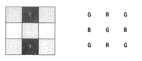
より具体的には、シングル・センサ・デジタル・カメラは、光路内でCFAの後に置かれているイメージ・センサ・アレイを使用して画像を取り込む。最も一般的なモザイクCFAはベイヤー・モザイク・パターン(Bayer mosaic pattern)と呼ばれる。ベイヤー・モザイク・パターン(またはベイヤー・フィルタ)は図1に示されている。ピクセルの2×2の集まり毎に、対角線で向かい合う2つのピクセルは、緑色フィルタを持ち、他の2つのピクセルは赤色と青色のフィルタを備える。緑色(G)は、人間に対して多くの輝度情報を伝達するため、そのサンプリング・レートは、赤色(R)および青色(B)の輝度の2倍である(例えば、特許文献1参照)。ベイヤー・フィルタが開示されている。 More specifically, a single sensor digital camera captures an image using an image sensor array that is placed after the CFA in the optical path. The most common mosaic CFA is called the Bayer mosaic pattern. The Bayer mosaic pattern (or Bayer filter) is shown in FIG. For each 2 × 2 collection of pixels, the two pixels facing diagonally have a green filter, and the other two pixels have red and blue filters. Since green (G) transmits a lot of luminance information to humans, its sampling rate is twice that of red (R) and blue (B) (see, for example, Patent Document 1). A Bayer filter is disclosed.
使用可能なデモザイク処理手法は多数ある。最も単純なデモザイク処理手法の1つは、双線形補間(bilinear interpolation)である。一般に、双線形補間は、3つの色平面を使用し、3つの色平面は、対称双線形補間(symmetric bilinear interpolation)を使用して独立して補間される。この補間では、補間される色と同じ色を持つ、ピクセルの最も近傍のピクセルを使用する。詳細には、図1を再び参照すると、双線形補間では、ピクセル位置(i,j)に対する緑色値g(i,j)で、そこが赤色または青色ピクセルと成っている緑色値g(i,j)は、以下の式で近隣の緑色値の平均をとることにより計算される。 There are many demosaicing techniques that can be used. One of the simplest demosaicing techniques is bilinear interpolation. In general, bilinear interpolation uses three color planes, and the three color planes are interpolated independently using symmetric bilinear interpolation. This interpolation uses the pixel closest to the pixel that has the same color as the interpolated color. Specifically, referring again to FIG. 1, in bilinear interpolation, a green value g (i, j) for a pixel location (i, j), which is a red or blue pixel. j) is calculated by taking the average of the neighboring green values in the following equation:

式(1)は、図1の「+」のマークの付いているピクセル(「現在ピクセル」ともいう)での緑色値を、「・」のマークの付いている観察された緑色値の平均として推定することに対応する。現在ピクセルは赤色を有し、したがって、緑色および青色の値は補間される必要があることに留意されたい。画像境界においては、その画像の範囲内に入るピクセルのみが含まれ、分数部(scaling)は調整される。 Equation (1) calculates the green value at the pixel marked “+” in FIG. 1 (also referred to as “current pixel”) as the average of the observed green values marked with “•”. Corresponds to the estimation. Note that the current pixel has a red color, so the green and blue values need to be interpolated. At the image boundary, only pixels that fall within the range of the image are included, and the scaling is adjusted.
双線形補間を使用して所定のピクセルで欠落している色の補間を行う方法は、図2A〜Hに図形で示されている。図2A〜Hに示されているように、双線形手法では、通常、小さなサポート領域(region of support)を使用する。このサポート領域は、それらの値が所定のピクセルの補間に関して考慮される近傍ピクセルからなるサイズである。図2A〜Hに示されているように、後述の双線形補間法に対するサポート領域は、通常、3×3ピクセルのサポート領域である。サポート領域のこの小さな部分を使用することで、メモリ使用量および計算複雑度を最小限に抑えられる。 A method of interpolating missing colors at a given pixel using bilinear interpolation is illustrated graphically in FIGS. As shown in FIGS. 2A-H, bilinear approaches typically use a small region of support. This support area is a size consisting of neighboring pixels whose values are considered for interpolation of a given pixel. As shown in FIGS. 2A-H, the support area for bilinear interpolation described below is typically a 3 × 3 pixel support area. By using this small portion of the support area, memory usage and computational complexity can be minimized.
図2Aおよび2Bを参照すると、所定のピクセルで緑色値を求めるための式(1)の双線形補間法が例示されている。図2Aで、赤色ピクセルにおける緑色値は、赤色ピクセルの近隣の緑色ピクセルを使用することにより求められる。これらの近隣緑色ピクセルは、図2Aではマーク「1」が記されている。同様に、図2Bでは、青色ピクセルにおける緑色値は、青色ピクセルの近隣の緑色ピクセルを使用することにより求められる。ここでも、この緑色ピクセルはマーク「1」が記される。 Referring to FIGS. 2A and 2B, the bilinear interpolation method of equation (1) for determining the green value at a given pixel is illustrated. In FIG. 2A, the green value at the red pixel is determined by using the green pixel adjacent to the red pixel. These neighboring green pixels are marked with a mark “1” in FIG. 2A. Similarly, in FIG. 2B, the green value at the blue pixel is determined by using the green pixel adjacent to the blue pixel. Again, this green pixel is marked with the mark “1”.
欠落している赤色(R)または青色(B)を求めるために、やはり式(1)を適用する。しかし、今度は、対角線クロスパターンが使用される。ただし、除外は、緑色ピクセルとなるピクセル位置(i,j)については、補間された赤色値は、すぐ近くに2つの赤色ピクセルのみがあるので、2つの赤色近隣ピクセルのみの平均をとって出力されることである。青色値を求めることについても、同じことが言える。式(1)の計算が簡単になるほかに、その出力値は入力値の同じダイナミックレンジを持つことが保証され、したがって出力値に対するオーバーフロー検出および制御ロジックは必要ないことに留意されたい。 Equation (1) is again applied to determine the missing red (R) or blue (B). However, this time a diagonal cross pattern is used. However, the exclusion is that for pixel position (i, j) that is a green pixel, the interpolated red value has only two red pixels in the immediate vicinity, so only the average of the two red neighboring pixels is output. It is to be done. The same is true for determining the blue value. Note that, besides simplifying the calculation of equation (1), its output value is guaranteed to have the same dynamic range of the input value, and thus no overflow detection and control logic is required for the output value.
より詳細には、図2C〜Eは、所定のピクセルの赤色値を求めるための式(1)の双線形補間法を例示している。特に、図2Cでは、2つの赤色近隣ピクセルを使用することにより赤色の横行および青色の縦列の緑色ピクセルのところの赤色値が求められる。同様に、図2Dでは、赤色の縦列内の2つの赤色近隣ピクセルを使用することにより青色の横行および赤色の縦列の緑色ピクセルのところの赤色値が求められる。図2Eでは、青色ピクセルのところの赤色値は、4つの近隣赤色ピクセルを使用することにより求められる。図2C〜Eでは、双線形補間法で使用される近隣赤色ピクセルのそれぞれに対しマーク「1」が付けられる。 More specifically, FIGS. 2C-E illustrate the bilinear interpolation method of Equation (1) for determining the red value of a given pixel. In particular, in FIG. 2C, the red value at the green pixel in the red row and blue column is determined by using two red neighbors. Similarly, in FIG. 2D, the red value at the green pixel in the blue row and red column is determined by using two red neighbors in the red column. In FIG. 2E, the red value at the blue pixel is determined by using four neighboring red pixels. In FIGS. 2C-E, a mark “1” is attached to each of the neighboring red pixels used in bilinear interpolation.
同様に、図2F〜Hは、所定のピクセルで青色値を求めるための式(1)の双線形補間法を例示している。特に、図2Fでは、2つの青色近隣ピクセルを使用することにより青色の横行および赤色の縦列の緑色ピクセルのところの青色値が求められる。図2Gでは、青色の縦列内の2つの赤色近隣ピクセルを使用することにより赤色の横行および青色の縦列の緑色ピクセルのところの青色値が求められる。図2Hでは、赤色ピクセルの青色値は、4つの近隣青色ピクセルを使用することにより求められる。図2F〜Hでは、双線形補間法で使用される近隣青色ピクセルのそれぞれに対しマーク「1」が付けられる。 Similarly, FIGS. 2F-H illustrate the bilinear interpolation method of Equation (1) for determining the blue value at a given pixel. In particular, in FIG. 2F, the blue value at the green pixel in the blue row and red column is determined by using two blue neighbors. In FIG. 2G, the blue value at the red row and the green pixel in the blue column is determined by using two red neighbors in the blue column. In FIG. 2H, the blue value of the red pixel is determined by using four neighboring blue pixels. In FIGS. 2F-H, a mark “1” is attached to each of the neighboring blue pixels used in bilinear interpolation.
しかし、上述の双線形補間法の問題の1つは、それらがカラー画像内に著しいアーティファクトが発生するという点にある。このことは、双線形補間ではRGB値間の統計的相関を考慮しないので、特に画像内のエッジおよびその他の高周波成分にわたって言える。例えば、図2Dおよび2Fを参照し、ピクセル強度値に急激な変化があり、したがって一番右の縦列内のすべてのピクセルが他のピクセルよりもかなり明るいと仮定する。すると、(図2Fの)中央のピクセルの補間された青色値は、いくぶん明るくなり、それは、右の隣接する青色が非常に明るいからである。しかし、(図2Dの)同じピクセルの補間された赤色値は、明るくならない、それは、2つの隣接する赤色があまり明るくないからである。したがって、この場合、補間された明るい青色ピクセルおよびそれほど明るくない補間された赤色ピクセルがあり、過剰な青色および不足する赤色は、補間されたピクセル色をシアン寄りに着色させることになり、カラーフリンジのアーティファクトを生じさせる。そのため、双線形補間法は高速で、あまり計算量を必要とせず、実装しやすいが、著しいアーティファクト(主にボケとカラーフリンジ)が発生するため出力される画像品質が低いという点で悪評が高い。 However, one of the problems with the above-described bilinear interpolation methods is that they cause significant artifacts in the color image. This is especially true across edges and other high frequency components in the image because bilinear interpolation does not consider the statistical correlation between RGB values. For example, referring to FIGS. 2D and 2F, assume that there is an abrupt change in pixel intensity values, so that all pixels in the rightmost column are significantly brighter than the other pixels. The interpolated blue value of the center pixel (in FIG. 2F) is then somewhat brighter because the right adjacent blue color is very bright. However, the interpolated red value of the same pixel (of FIG. 2D) does not become bright because two adjacent reds are not so bright. So in this case there are interpolated bright blue pixels and less bright interpolated red pixels, and the excess blue and the deficient red will cause the interpolated pixel color to be colored closer to cyan, and the color fringe Create artifacts. For this reason, the bilinear interpolation method is fast, does not require much calculation, and is easy to implement, but it is notorious for its low output image quality due to significant artifacts (mainly blurring and color fringes). .
多少複雑度に成っても、RGB値間の相関を考慮する補間法がベターである。ある一群の補間法では、改良された線形フィルタを使用することによりそのような補正を考慮している(例えば、非特許文献1参照)。他の一群の補間法では、非線形フィルタを使用することによりそのような補正を考慮している。それらの非線形フィルタは、本質的に、補間平滑化を画像のアクティビティやエッジの量(measure of image activity or edginess)に合わせて適合される(例えば、非特許文献2および非特許文献3参照)。
An interpolation method that takes into account the correlation between RGB values is better, even if it is somewhat complicated. A group of interpolation methods consider such correction by using an improved linear filter (see, for example, Non-Patent Document 1). Another group of interpolation methods considers such corrections by using non-linear filters. These non-linear filters are essentially adapted to interpolate smoothing according to image activity or edge (measure of image activity or edginess) (see, for example,
RGBチャネル間の相関性を利用することは、非線形補間法においてデモザイク処理のパフォーマンスを高めることの背後にある主要な考え方である。特に、輝度/クロミナンス分解では、クロミナンス成分は複数のピクセルにまたがってあまり変化がないと仮定されている。色相一定方式(例えば、特許文献2参照)では、緑色チャネルは双線形補間され、その後、R/GおよびB/Gの比として定義される一定の色相を維持するように、赤色および青色チャネルが補間される。しかし、Freemanによるこの手法の1つの問題点は、これらの比を計算するコストをかけても、この手法は、なお目につくアーティファクトを生じさせる、ということにある。さらに、補間の計算で複雑な演算(除算および乗算など)を使用するため、計算の複雑度、処理のオーバーヘッド、および実装コストが大幅に増大する。 Utilizing the correlation between RGB channels is the main idea behind enhancing the performance of demosaicing in nonlinear interpolation. In particular, in luminance / chrominance decomposition, it is assumed that the chrominance component does not change much across multiple pixels. In a constant hue scheme (see, for example, Patent Document 2), the green channel is bilinearly interpolated and then the red and blue channels are maintained so as to maintain a constant hue defined as the ratio of R / G and B / G. Interpolated. However, one problem with this Freeman approach is that, even at the cost of calculating these ratios, this approach still produces noticeable artifacts. In addition, the use of complex operations (such as division and multiplication) in interpolation calculations greatly increases computational complexity, processing overhead, and implementation costs.
非線形補間法の結果を改善するには、双線形補間された緑色ピクセルから開始し、その後、中央値フィルタ(median filters)を色差R−GおよびB−Gの補間された値に適用する、ことによって得られる。パフォーマンスの改善は、グラディエントに基づく非線形手法(gradient-based nonlinear techniques)を使用して得ることができ、これは、通常、エッジ方向を推定し、補間式を調整して、フィルタリングが、エッジ方向を横切るのではなくそれにそって優先的に実行されるように補間する(例えば、特許文献3参照)。特許文献3のLarocheおよびPrescottの手法は、赤色および青色の両方のチャネルを使用して、緑色チャネルを補間してエッジ方向を決定しており、緑色チャネルに対する式(1)の中の項に与える不均等な重み付けを決定している。その後、色差R−GおよびB−Gを補間する。ある手法では、一次と二次の両方のピクセル差を考慮することによりLarocheおよびPrescottの手法の改善を行っている(例えば、非特許文献4参照)。しかし、これらのグラディエント手法(gradient techniques)では、単にグラディエントを計算し、これを、使用すべき補間法を選択するために使用しているだけである。 To improve the result of the non-linear interpolation method, start with bilinearly interpolated green pixels, and then apply median filters to the interpolated values of the color differences RG and BG Obtained by. Performance improvements can be obtained using gradient-based nonlinear techniques, which typically estimate the edge direction, adjust the interpolation formula, and filter the edge direction. Interpolation is performed so as to be performed preferentially along the line instead of crossing (see, for example, Patent Document 3). The method of Laroche and Prescott in US Pat. No. 6,057,049 uses both red and blue channels to interpolate the green channel to determine the edge direction and gives the term in equation (1) for the green channel Unequal weights are determined. Thereafter, the color differences RG and BG are interpolated. In one method, the Laroche and Prescott methods are improved by considering both the primary and secondary pixel differences (see, for example, Non-Patent Document 4). However, these gradient techniques simply calculate the gradient and use it to select the interpolation method to be used.
可変する数のグラディエントを使用することを考慮することによる上述の手法の改善が開示されている(例えば、非特許文献5参照)。ソフト・デシジョン・ルール(soft decision rules)を使用して水平方向および垂直方向からの補間結果を組み合わせる、さらに単純であるが、効率のよいアルゴリズムが論文に開示されている(例えば、非特許文献6参照)。 Improvements to the above approach by considering using a variable number of gradients are disclosed (see, for example, Non-Patent Document 5). A simpler but more efficient algorithm that combines the results of interpolation from the horizontal and vertical directions using soft decision rules has been disclosed in the paper (eg, Non-Patent Document 6). reference).
反復法であれば、青色および赤色の補間からの結果を使用して緑色の補間を補正すること、またその逆の操作を使用することで、さらに改善を行うことができる。これは論文(例えば、非特許文献7参照)で説明されている手法の基礎である。非特許文献7のKimmelの方式では、補間ステップは、色相一定法とグラディエントに基づく方法の組み合わせに基づいている。反復射影に基づく手法は、論文(例えば、非特許文献8参照)に提示されている。非特許文献8のGunturkの手法は、ポピュラーな標準的テスト画像群に対しこれまでで最もパフォーマンスがよい。しかし、Gunturkの手法に問題の1つは、複雑度が非常に高くなるという点にある(1入力ピクセルあたり480回程度の演算)。 If iterative, further improvements can be made by correcting the green interpolation using the results from the blue and red interpolations, and vice versa. This is the basis of the method described in the paper (for example, refer nonpatent literature 7). In Kimmel's method of Non-Patent Document 7, the interpolation step is based on a combination of a constant hue method and a gradient-based method. A method based on iterative projection is presented in a paper (for example, see Non-Patent Document 8). The Gunturk method of Non-Patent Document 8 has the best performance so far for popular standard test images. However, one of the problems with Gunturk's method is that the complexity becomes very high (about 480 operations per input pixel).
上述の非線形補間法では、通常、双線形補間法で使用されるより大きなサポート領域を使用する。例えば、5×5ピクセルのサポート領域は、これらの非線形手法では典型的なものである。5×5のサポート領域であれば、RGB値同士の間のよい相関が得られ、高品質の画像が出力される。サポート領域が小さいほど、画質は大きく低下し、サポート領域が大きいほど、より多くのメモリを必要とし、計算の複雑度が大幅に増大する。 The nonlinear interpolation method described above typically uses a larger support area than that used in bilinear interpolation. For example, a 5 × 5 pixel support area is typical for these nonlinear approaches. In the case of a 5 × 5 support area, a good correlation between RGB values is obtained, and a high-quality image is output. The smaller the support area, the lower the image quality. The larger the support area, the more memory is required and the computational complexity increases significantly.
したがって、必要なのは、双線形補間法の単純さとスピードを保ったまま、非線形補間法などのより複雑度の高い手法の高品質画像を出力する、カラー画像をデモザイクする補間法である。さらに必要なのは、パフォーマンスを改善するためにRGB値の間の相関を考慮する高品質補間法である。さらに必要なのは、グラディエントを計算することによりこの補正を考慮し、この計算されたグラディエントを、補間法を選択するためだけに使用するのではなく、直接補正項として使用する補間法である。さらに必要なのは、品質改善のため双線形手法よりも広い範囲のサポート領域(このサポート領域は非線形手法で使用されているサポート領域に匹敵する)を使用する補間法である。さらに必要なのは、スピードを上げ、計算の複雑度を回避し、安価な実装を可能にするために補間を計算するときに単純数学的演算(加算など)だけがあればよい補間法である。 Therefore, what is needed is an interpolation method for demosaicing a color image that outputs a high quality image of a higher complexity method such as a nonlinear interpolation method while maintaining the simplicity and speed of the bilinear interpolation method. What is further needed is a high quality interpolation method that considers the correlation between RGB values to improve performance. What is further needed is an interpolation method that takes this correction into account by calculating the gradient and uses the calculated gradient as a correction term directly rather than just for selecting an interpolation method. What is further needed is an interpolation method that uses a wider range of support than the bilinear approach for quality improvement (this support area is comparable to the support area used in the nonlinear approach). What is further needed is an interpolation method that only requires simple mathematical operations (such as addition) when calculating interpolation to increase speed, avoid computational complexity, and allow for an inexpensive implementation.
本明細書で開示されている本発明は、デジタル・カラー画像をデモザイクするための高品質な線形補間の方法およびシステムを含む。本発明は、実装が簡単で、コスト効率の高い高品質補間を実現することにより、現在の補間法の上述の不備を克服する。つまり、本明細書で開示されているグラディエント補正線形補間の方法およびシステムは、現在のピクセルからの色情報を使用して補正項を取得する。次に、この補正項と従来技術の補間との線形結合を作り、現在のピクセルの位置における欠落色の推定を改善する。本グラディエント補正線形補間の方法およびシステムは、優れたパフォーマンスを持ち、現在の従来技術による線形デモザイク手法よりも複雑度が低い。さらに、本グラディエント補正線形補間の方法およびシステムは、さらに大きな複雑度を持つ多くの従来技術の非線形デモザイク手法に勝るパフォーマンスを発揮する。 The invention disclosed herein includes high quality linear interpolation methods and systems for demosaicing digital color images. The present invention overcomes the above deficiencies of current interpolation methods by realizing high quality interpolation that is simple to implement and cost effective. That is, the gradient-corrected linear interpolation method and system disclosed herein uses color information from the current pixel to obtain a correction term. Next, a linear combination of this correction term and prior art interpolation is made to improve the estimation of missing colors at the current pixel location. The gradient-corrected linear interpolation method and system has superior performance and is less complex than current prior art linear demosaicing techniques. In addition, the gradient-corrected linear interpolation method and system outperform many prior art nonlinear demosaicing techniques with greater complexity.
本グラディエント補正線形補間の方法およびシステムは、デジタル・カメラにより取り込まれたカラー画像を処理することができる。表示に先立って、この画像は、グラディエント補正線形補間の方法およびシステムを使用してデモザイク処理が行われる。それとは別に、取り込まれたデジタル・カラー画像を圧縮モザイク形式でコンピューティング・デバイスに格納することもできる。コンピューティング・デバイス上のアプリケーションからその画像にアクセスする必要がある場合、そのアプリケーションは、通常、適切なアプリケーション・プログラミング・インターフェース(API)を呼び出してその圧縮解除されたデータを取得する。ほとんどのアプリケーションでは、データがRGB形式であることを予期しているため、画像データが要求側アプリケーションに送られる前にデモザイク処理が実行されなければならない。 The gradient-corrected linear interpolation method and system can process color images captured by a digital camera. Prior to display, the image is demosaiced using gradient-corrected linear interpolation methods and systems. Alternatively, the captured digital color image can be stored on the computing device in a compressed mosaic format. When it is necessary to access the image from an application on the computing device, the application typically calls the appropriate application programming interface (API) to obtain the decompressed data. Since most applications expect the data to be in RGB format, demosaicing must be performed before the image data is sent to the requesting application.
グラディエント補正線形補間法は、補間で所望の色が使用される場合に、現在の色を持つ現在のピクセルの位置における所望の色の補間値を計算することを含む。次に、現在の色を使用して補正項が計算される。次に、この補正項と補間値との線形結合を作り、現在のピクセルの位置における所望の色の補正された補間値を得る。計算を簡素化し、計算資源をそのままで使用するために、この補間は従来技術の双線形補間(「背景技術」で説明したような補間)であるのが好ましい。しかし、この補間は、実質的に、線形補間および非線形補間を含む、使用可能な従来技術のデモザイク処理手法のいずれでもよい。 Gradient-corrected linear interpolation involves calculating an interpolated value of the desired color at the current pixel location with the current color when the desired color is used in the interpolation. Next, a correction term is calculated using the current color. Next, a linear combination of this correction term and the interpolated value is made to obtain a corrected interpolated value of the desired color at the current pixel location. In order to simplify the calculation and use the computational resources as is, this interpolation is preferably prior art bilinear interpolation (interpolation as described in “Background”). However, this interpolation can be virtually any of the available prior art demosaicing techniques, including linear and non-linear interpolation.
補正項は、現在のピクセルの現在の色から計算で求められたグラディエント補正項であるのが好ましい。例えば、現在のピクセルが、図2Cおよび2Dに示されているように、そのピクセルについて緑色値を決定できる、緑色ピクセルの位置における赤色値が所望される画像センサを備えるものと仮定する。グラディエント補正線形補間法では、そのピクセルの位置の緑色値および近隣の緑色ピクセルの値を使用することにより緑色ピクセルの位置のグラディエントを計算する。その後、そのグラディエント値の固定部分(ゲイン係数で制御されるのが好ましい)を、補間された赤色値(好ましくは、双線形補間赤色値)に加える。いくつかの従来技術のデモザイク処理手法ではグラディエントを計算するが、そのグラディエントは、補間の計算を制御するために使用される。他方、本明細書で開示されているグラディエント補正線形補間法では、グラディエントを補正後として直接使用する。つまり、いくつかの従来技術のデモザイク処理手法では、グラディエントを計算し、そのグラディエントをグラディエントに基づいて補間法を選択するために使用するが、一方、グラディエント補正線形補間法では、そのグラディエントを直接、従来技術のデモザイク処理手法により得られた値に直接作用させて補正するために、使用して使用する。 The correction term is preferably a gradient correction term calculated from the current color of the current pixel. For example, assume that the current pixel comprises an image sensor where a red value at the location of the green pixel is desired, as can be determined for that pixel, as shown in FIGS. 2C and 2D. In gradient-corrected linear interpolation, the gradient of the green pixel position is calculated by using the green value of that pixel position and the values of neighboring green pixels. Thereafter, a fixed portion of the gradient value (preferably controlled by a gain factor) is added to the interpolated red value (preferably a bilinearly interpolated red value). Some prior art demosaicing techniques calculate a gradient, which is used to control the interpolation calculation. On the other hand, in the gradient-corrected linear interpolation method disclosed in this specification, the gradient is directly used as corrected. That is, some prior art demosaicing techniques compute a gradient and use that gradient to select an interpolation method based on the gradient, while gradient-corrected linear interpolation uses the gradient directly, Used to correct by directly acting on the value obtained by the prior art demosaicing method.
グラディエント補正項は、補間値に線形に結合される。グラディエント補正項を補間値に加えて、所望の色の推定値を改善するのが好ましい。グラディエントを使用する従来技術のデモザイク処理手法では、通常、非線形フィルタ、「if」文、および除算など、グラディエントに基づく複雑な演算子を計算し、使用する。グラディエント補正線形補間法では、線形演算を使用してグラディエント補正項と補間値との線形結合を作ることにより計算を簡素化するが、その線形演算は、加算であるのが好ましい。 The gradient correction term is linearly coupled to the interpolated value. Preferably, a gradient correction term is added to the interpolated value to improve the desired color estimate. Prior art demosaicing techniques that use gradients typically compute and use complex operators based on gradients, such as non-linear filters, “if” statements, and division. In the gradient correction linear interpolation method, the calculation is simplified by creating a linear combination of the gradient correction term and the interpolation value using a linear operation, and the linear operation is preferably addition.
グラディエント補正線形補間法は、さらに、グラディエント補正ゲインをグラディエント補正項に適用することも含む。このグラディエント補正ゲインは、補間値に適用されるグラディエント補正の量に影響を及ぼす。例えば、グラディエント補正ゲインが0.8であれば、グラディエント補正の80%のみが、補間値に線形に結合される。グラディエント補正ゲインは、いろいろな方法で選択できる。最適なグラディエント補正ゲインは、平均平方誤差を最小値にすることによって算出される。この最適値の近似は、整数演算、非除算演算、またはその両方を使っての計算を可能にする。グラディエント補正は、カラー画像センサの特性またはデジタル・カメラ・システム全体の特性に基づいて選択することもできる。さらに、グラディエント補正ゲインは、必要ならば、カラー画像の統計量に基づいて、画像内で変えることも可能である。それらの統計量は、画像の大域的統計量、画像の局所的統計量、またはその両方を含むことができる。 The gradient-corrected linear interpolation method further includes applying a gradient correction gain to the gradient correction term. This gradient correction gain affects the amount of gradient correction applied to the interpolated value. For example, if the gradient correction gain is 0.8, only 80% of the gradient correction is linearly coupled to the interpolated value. The gradient correction gain can be selected in various ways. The optimum gradient correction gain is calculated by minimizing the mean square error. This approximation of optimal values allows computations using integer arithmetic, non-division arithmetic, or both. The gradient correction can also be selected based on the characteristics of the color image sensor or the characteristics of the entire digital camera system. Furthermore, the gradient correction gain can be varied in the image based on the color image statistics, if necessary. Those statistics may include global statistics of the image, local statistics of the image, or both.
グラディエント補正線形補間法は、サポート領域を、現在のピクセルを直に囲むピクセル近傍のサイズとして定義することを含む。そこで、現在の色を持つ現在のピクセルに最も近いピクセルを含むようにサポート領域を選択し、そのサポート領域を使用して、補間値および補正項を計算する。サポート領域は、現在のピクセルを中心とする5×5ピクセル領域を含むのが好ましい。それとは別に、サポート領域は5×5ピクセル領域より広くてもよい。複数のサポート領域があってもよい。例えば、第1のサポート領域を使用して、補間値を計算し、第2のサポート領域を使用して、補正項を計算するようにすることができる。 Gradient-corrected linear interpolation involves defining the support area as the size of the pixel neighborhood that immediately surrounds the current pixel. Therefore, the support area is selected so as to include the pixel closest to the current pixel having the current color, and the interpolation value and the correction term are calculated using the support area. The support area preferably includes a 5 × 5 pixel area centered on the current pixel. Alternatively, the support area may be wider than the 5 × 5 pixel area. There may be multiple support areas. For example, a first support region can be used to calculate an interpolation value, and a second support region can be used to calculate a correction term.
グラディエント補正線形補間システムでは、上述の方法を使用して、素早く、単純で、効率のよい方法により、所定のピクセルの位置の欠落色の高品質補間値を出力する。グラディエント補正線形補間システムは、現在の色を持つ現在のピクセルを選択する現在のピクセル・セレクタ、および現在のピクセルの位置で欠落し、所望される色値の第1の補間値を計算する補間モジュールを備える。グラディエント補正線形補間システムは、さらに、補間値に対する補正項を計算する補正項モジュール、および補間値と補正項の線形結合を作り、現在のピクセル位置の所望の(または欠落している)色値を取得する線形結合モジュールも備える。 A gradient-corrected linear interpolation system uses the method described above to output a high quality interpolated value of missing colors at a given pixel location in a quick, simple and efficient manner. A gradient-corrected linear interpolation system includes a current pixel selector that selects a current pixel having a current color, and an interpolation module that is missing at the current pixel location and calculates a first interpolation value of a desired color value Is provided. The gradient-corrected linear interpolation system further creates a correction term module that calculates a correction term for the interpolated value, and a linear combination of the interpolated value and the correction term to obtain the desired (or missing) color value at the current pixel position. A linear combination module is also provided.
補正項計算モジュールは、さらに、適用される補正の量を選択するグラディエント補正セレクタも含む。さらに、補正項計算モジュールは、現在のピクセルを中心とするサポート領域を定義するサポート領域モジュール、および現在のピクセルを使用してグラディエント補正を計算するグラディエント補正モジュールをも含む。さらに、補正項計算モジュールは、調整されたグラディエント補正が出力されるように、計算されたグラディエント補正にゲインを適用するグラディエント補正ゲイン適用モジュールも含む。 The correction term calculation module further includes a gradient correction selector that selects the amount of correction to be applied. In addition, the correction term calculation module also includes a support area module that defines a support area centered on the current pixel, and a gradient correction module that calculates a gradient correction using the current pixel. The correction term calculation module also includes a gradient correction gain application module that applies a gain to the calculated gradient correction so that the adjusted gradient correction is output.
本発明は、本発明の態様を例示する以下の図面および添付図面を参照することにより理解を深めることができる。他の特徴および利点は、本発明の原理を例により説明している、付属の図面とともに、以下の詳細な説明を読むと明らかになる。 The present invention can be better understood with reference to the following drawings and attached drawings that illustrate embodiments of the invention. Other features and advantages will become apparent from the following detailed description, taken in conjunction with the accompanying drawings, illustrating by way of example the principles of the invention.
そこで、全体として類似の参照番号が対応するパーツを表す図面を参照することにする。 Accordingly, reference will be made to the drawings representing parts corresponding to like reference numbers as a whole.
本発明の以下の説明では、本発明の一部をなし、本発明を実施できる具体的実施形態が図で示されている、付属の図面を参照する。他の実施形態を利用し、本発明の範囲および精神から逸脱することなく構造上の変更を加えることができることは理解されるであろう。 In the following description of the invention, reference is made to the accompanying drawings, which form a part hereof, and in which are shown by way of illustration specific embodiments in which the invention may be practiced. It will be understood that other embodiments may be utilized and structural changes may be made without departing from the scope and spirit of the invention.
I.はじめに
ほとんどすべての現在のデジタル・カメラはカラー画像内の各ピクセルに対し単一のセンサを使用する。その結果、ピクセル毎に、赤色、緑色、および青色の3色(RGB)のうちの1つのみが取り込まれる。しかし、カラー画像を出力するには、すべてのピクセルでそれぞれのRGB色値が必要である。したがって、カメラは、「デモザイク処理」と呼ばれる手法を使用して、すべてのピクセルのところの欠落色値を生成する。
I. Introduction Almost all current digital cameras use a single sensor for each pixel in a color image. As a result, only one of the three colors (RGB) of red, green, and blue is captured for each pixel. However, to output a color image, each pixel needs its own RGB color value. Thus, the camera uses a technique called “demosaicing” to generate missing color values at every pixel.
残念ながら、欠落しているRGBデータを補間する手法は、複雑度と品質との間で二律背反にある。例えば、双線形補間法では、単純な計算演算、線形演算子、および小さなサポート領域(3×3サポート領域など)を使用する。これにより、双線形補間法は高速で、計算量があまり多くなく、実装しやすいものとなる。しかし、これらの双線形手法は、さらに、カラー画像に著しいアーティファクトを発生し、そのため、画質が著しく劣化する場合がある。他方では、いくつかの非線形補間法では、顕著に改善された画質が得られるが、速度が著しく低く、大きな処理能力を使用し、複雑な計算演算を使用し、また実装しにくい。 Unfortunately, the method of interpolating the missing RGB data is a tradeoff between complexity and quality. For example, bilinear interpolation uses simple computational operations, linear operators, and small support areas (such as 3 × 3 support areas). As a result, the bilinear interpolation method is fast, does not require much calculation, and is easy to implement. However, these bilinear approaches also generate significant artifacts in the color image, which can significantly degrade image quality. On the other hand, some non-linear interpolation methods provide significantly improved image quality, but are significantly slower, use large processing power, use complex computational operations and are difficult to implement.
本明細書で開示されているグラディエント補正線形補間の方法およびシステムは、カラー画像のデモザイク処理を行う新しい補間法を備える。この方法およびシステムでは、現在の手法により計算された補間値を使用し、(所定のピクセルのところの所望の色のグラディエントなどの)補正項を計算し、補間値と補正項との線形に結合する。この方法およびシステムは、低負荷の演算子(加算およびシフトなど)で固定した線形演算を実行することにより、計算の複雑度を最小限度に抑える。さらに、グラディエントを単に補間方法を選択する手段としてではなく、補正項として直接使用することにより、グラディエント補正線形補間の方法およびシステムは、複雑なプログラミング(実行速度を遅くする多数の「if」文など)の必要性を回避し、その結果として実装を簡素化する。このグラディエント補正線形補間ではRGB値間の相関を考慮するので画質は向上する。グラディエント補正線形補間の方法およびシステムは、さらに、非線形手法と同様に、より大きなサポート領域を利用して、欠落色値の推定値を改善する。 The gradient-corrected linear interpolation method and system disclosed herein comprises a new interpolation method that performs demosaicing of color images. This method and system uses the interpolated values calculated by the current method, calculates correction terms (such as the desired color gradient at a given pixel), and linearly combines the interpolated values and the correction terms To do. This method and system minimizes computational complexity by performing fixed linear operations with low-load operators (such as addition and shift). Further, by using the gradient directly as a correction term rather than simply as a means of selecting an interpolation method, the gradient-corrected linear interpolation method and system can be used for complex programming (such as a number of “if” statements that slow down execution). ), And as a result, simplify the implementation. This gradient-corrected linear interpolation improves the image quality because the correlation between RGB values is taken into account. The gradient-corrected linear interpolation method and system further utilizes a larger support area to improve the estimated missing color value, similar to the non-linear approach.
グラディエント補正線形補間の方法およびシステムを使用すると、双線形補間法と比べたときに、ピーク信号対雑音比(PSNR)は5.5dB以上改善され、いくつかの現在の線形補間法と比べたときには赤色(R)および青色(B)の補間値は約0.7dB改善される。グラディエント補正線形補間の方法およびシステムは、さらに、線形処理によるアーティファクトの混入もなく、および大幅な計算複雑度の低減の点で、ほとんどの非線形補間法より性能が優れている。 Using gradient-corrected linear interpolation methods and systems, the peak signal-to-noise ratio (PSNR) is improved by over 5.5 dB when compared to bilinear interpolation, and when compared to some current linear interpolation methods. The red (R) and blue (B) interpolation values are improved by about 0.7 dB. The gradient-corrected linear interpolation method and system further outperform most non-linear interpolation methods in that there is no artifacts due to linear processing and a significant reduction in computational complexity.
II.概要
図3Aおよび3Bは、本明細書で開示されているグラディエント補正線形補間のシステムおよび方法の2つの実施例を説明するブロック図である。図3Aおよび3Bは、単に、グラディエント補正線形補間のシステムおよび方法を実装し、使用できるようにする複数の方法のうちの2つにすぎないことに留意されたい。
II. Overview FIGS. 3A and 3B are block diagrams illustrating two embodiments of the gradient-corrected linear interpolation system and method disclosed herein. It should be noted that FIGS. 3A and 3B are merely two of a number of methods that allow a gradient-corrected linear interpolation system and method to be implemented and used.
図3Aを参照すると、第1の実施例では、グラディエント補正線形補間システム300は、デジタル・カメラ・システム310内に常駐する。一般に、グラディエント補正線形補間システム300では、グラディエント補正線形補間法を使用して、イメージ・センサ・アレイ315から取り出した画像データを処理し、各ピクセル320に対する欠落色値を出力する。より具体的には、図3Aに示されているように、グラディエント補正線形補間システム300は、イメージ・センサ・アレイ315を備えるデジタル・カメラ・システム310の一部である。アレイ315は、複数のイメージ・センサ(図3Aでは円で示されている)からなり、それぞれのイメージ・センサは単一の色値を決定することができる。
Referring to FIG. 3A, in the first embodiment, the gradient corrected
イメージ・センサ・アレイ315は、センサ基板330、カラー・フィルタ・アレイ(CFA)340、およびマイクロ・レンズ・アレイ350を備える。マイクロ・レンズ・アレイ350は、CFA 340の上に配置され、さらに、図3Aおよび3Bで点線により示されているように、基板330の上に配置される。取り込まれる画像(image)(図に示されていない)から出た光は、デジタル・カメラ・システム310内に入る(矢印355で示されているように)。マイクロ・レンズ・アレイ350の目的は、入射光355の焦点を(単一イメージ・センサで表されている)各ピクセル上に合わせることである。CFA 340は、各ピクセルの色応答を変更する。センサ基板330は、特定の色の入射光(CFA 340により示されているように)を取り込み、電気信号を発生する。このようにして、イメージ・センサ・アレイ315は、イメージ・センサ・アレイ315内に配列されている赤色、緑色、および青色のセンサにより入射光355のサンプリングを行う。
The
イメージ・センサ・アレイ315内の各ピクセルは、赤色、緑色、または青色センサの出力である。したがって、センサ出力は、イメージ・センサ・アレイ315内の各ピクセルに対する単一の色値に対応するそれぞれのセンサからの電気的信号である。出力は、生(raw)のモザイク・パターンのピクセル・データ360である。上述のように、フル・カラー画像を表示するために、赤色、緑色、および青色に対する色情報がピクセル毎に取得されなければならない。これは、モザイク・パターンのピクセル・データ360内の欠落色値を、デモザイク処理する、つまり補間することにより達成される。
Each pixel in the
グラディエント補正線形補間システム300は、新規性のあるデモザイク処理手法を使用して、欠落色値の高品質推定値を補間する。グラディエント補正線形補間システム300は、デジタル・カメラ・システム310上に配置されている処理デバイス370上に常駐する。後述のように、グラディエント補正線形補間システム300は、グラディエント補正線形補間法を使用して、イメージ・センサ・アレイ315内の各ピクセル320のところの欠落色値を取得する。
The gradient-corrected
そこで図3Bを参照すると、第2の実施例では、グラディエント補正線形補間システム300は、コンピューティング・デバイス380内に常駐する。生(raw)のモザイク・パターンのピクセル・データ360が、デジタル・カメラ・システム310からコンピューティング・デバイス380に送られる。このピクセル・データ360は、通常、インターフェース接続385を介してコンピューティング・デバイス380に送られ、このインターフェースはUSBインターフェース、IEEE 1394インターフェース、Bluetooth(R)インターフェース、またはデジタル・カメラ・システム310からコンピューティング・デバイス380に生のピクセル・データ360を搬送するのに適しているその他のインターフェースとすることができる。後述のように、グラディエント補正線形補間システム300は、グラディエント補正線形補間法を使用して、各ピクセル390のところの欠落色値を取得し、コンピューティング・デバイス380により使用できるようにする。
Referring now to FIG. 3B, in a second embodiment, the gradient-corrected
III.動作の概要
図3に示され、そこで使用されるグラディエント補正線形補間システム300および方法の動作について説明する。図4は、図3に示されているグラディエント補正線形補間システムの一般的な動作を説明する一般的な流れ図である。グラディエント補正線形補間法は、まず、カラー画像から現在のピクセルを入力することから始まる(ボックス400)。現在のピクセルは、関連付けられた現在の色を持つ。つまり、現在の色は、現在のピクセルのイメージ・センサがフィルタ処理されて受け取る色である。次に、現在のピクセルの所望の色について補間値が計算される(ボックス410)。つまり、現在のピクセルのところの欠落色は、補間されるか、または推定される。例えば、現在の色が緑色であれば、所望の色は赤色かまたは青色である。この補間は、従来技術の補間法であり、線形、双線形、非線形、双三次、およびランチョス補間法を含む、上述の補間法のいずれかを使用する。好ましい実施形態では、双線形補間法が使用される。さらに、補間値を計算するために、所望の色が使用される。所望の色の近隣ピクセルは、一般に、補間値を計算する際に使用される。
III. Operational Overview The operation of the gradient-corrected
その後、補正項が計算される(ボックス420)。この計算は、現在のピクセルの現在の色を使用して実行される。現在のピクセルは、通常、補正項を計算する際に、現在の色を持つ現在のピクセルの近隣ピクセルとともに使用される。好ましい実施形態では、補正項はグラディエント補正であり、後述のように、現在のピクセルのグラディエントを計算することにより求められる。 A correction term is then calculated (box 420). This calculation is performed using the current color of the current pixel. The current pixel is typically used along with the neighboring pixels of the current pixel with the current color when calculating the correction term. In the preferred embodiment, the correction term is a gradient correction and is determined by calculating the gradient of the current pixel, as described below.
グラディエント補正線形補間の方法およびシステムは、エッジに、クロミナンス成分よりもかなり強い輝度がある、新しい基準を備える。したがって、赤色ピクセルのところの緑色値の補間値を計算する場合、その場所の赤色値を捨てることはない。捨てるのではなく、本発明では、この貴重な情報を使用して補正項を計算する。対照的に、従来技術の補間法ではこの情報を捨ててしまう。本実施例では、その赤色値は、近隣の赤色値に対し従来技術の補間法を使用して補間された値と比較される。その赤色値がその推定値と異なる場合、そのピクセルのところに鋭い輝度変化があることを意味している可能性がある。そこで、本発明では、補正項の少なくとも一部を加えることにより補間された緑色値を(推定された輝度変化に対応して)補正する。そのような比較は、グラディエントに基づく補正項により暗黙のうちに実行され、したがって、「if」文または条件付き分岐ロジックは必要ない。 The gradient-corrected linear interpolation method and system provides a new criterion where the edges have a much stronger brightness than the chrominance component. Therefore, when calculating the interpolated value of the green value at the red pixel, the red value at that location is not discarded. Rather than discarding, the present invention uses this valuable information to calculate the correction term. In contrast, prior art interpolation methods discard this information. In this embodiment, the red value is compared to a value interpolated using a prior art interpolation method for neighboring red values. If the red value is different from the estimated value, it may mean that there is a sharp luminance change at the pixel. Therefore, in the present invention, the interpolated green value is corrected (corresponding to the estimated luminance change) by adding at least a part of the correction term. Such a comparison is performed implicitly by a gradient-based correction term, and thus no “if” statements or conditional branching logic is required.
最終的に、補間値と補正項との線形に結合され、現在のピクセルの所望の色の補正された補間値を得る(ボックス430)。好ましい実施形態では、補間値および補正項を足し合わせて、補正された補間値を得る。さらに、グラディエント補正ゲインをグラディエント補正項に適用し、補間値に線形に結合されるグラディエント補正値の量(または部分または割合)を決定することができる。後述のように、このグラディエント補正ゲインは、さまざまな手法を用いて選択できる。 Finally, the interpolated value and the correction term are linearly combined to obtain a corrected interpolated value of the desired color of the current pixel (box 430). In a preferred embodiment, the interpolated value and the correction term are added to obtain a corrected interpolated value. In addition, the gradient correction gain can be applied to the gradient correction term to determine the amount (or portion or percentage) of the gradient correction value that is linearly coupled to the interpolated value. As will be described later, this gradient correction gain can be selected using various methods.
従来技術の補間法と異なり、補正線形補間法で、例えば、赤色ピクセル位置での緑色値の補間値について補正項を計算する場合、その位置での赤色値は破棄されない。現在の色(赤色)は貴重な情報である。破棄するのではなく、グラディエント補正線形補間法では、その赤色値を、最も近い赤色サンプルについて補間値(または推定値)と比較する。その赤色値がその推定結果と異なる場合、現在のピクセルのところに鋭い輝度変化があることを示している可能性がある。したがって、グラディエント補正線形補間法では、補正項の少なくとも一部を補間値に線形に結合することにより、現在のピクセル(この実施例では緑色を有する)での従来技術による補間値を補正する。その場合、補正された値はこの推定された輝度を表す。 Unlike the interpolation method of the prior art, when the correction term is calculated for the interpolation value of the green value at the red pixel position by the correction linear interpolation method, the red value at that position is not discarded. The current color (red) is valuable information. Rather than discarding, gradient-corrected linear interpolation compares its red value with the interpolated value (or estimated value) for the closest red sample. If the red value is different from the estimation result, it may indicate that there is a sharp luminance change at the current pixel. Thus, with gradient-corrected linear interpolation, at least a portion of the correction term is linearly coupled to the interpolated value to correct the interpolated value according to the prior art at the current pixel (which has a green color in this embodiment). In that case, the corrected value represents this estimated luminance.
IV.動作の詳細および稼働実施例
図5は、グラディエント補正計算プロセスを例示する一般的な流れ図である。特に、グラディエント補正ゲインが決定される(ボックス500)。後述のように、ゲインは、さまざまな方法で決定することができる。次に、サポート領域は、カラー画像内の現在のピクセルを中心に定義される(ボックス510)。このサポート領域は、現在のピクセルなどの、所定のピクセルに関連付けられた各計算に関して色値が考慮される近傍のピクセルから成るサイズとして定義される。これらの計算は、補間値を計算すること、および補正項(グラディエントなど)を計算することを含む。
IV. Operational Details and Working Example FIG. 5 is a general flow diagram illustrating the gradient correction calculation process. In particular, a gradient correction gain is determined (box 500). As described below, the gain can be determined in various ways. A support area is then defined around the current pixel in the color image (box 510). This support area is defined as the size of neighboring pixels, such as the current pixel, for which color values are considered for each calculation associated with a given pixel. These calculations include calculating an interpolated value and calculating a correction term (such as a gradient).
次に、グラディエント補正が計算される(ボックス520)。このグラディエントは、現在のピクセル(現在の色を持つ)およびこれもまた現在の色を持つサポート領域内のピクセルを使用して計算される。その後、グラディエント補正ゲインがグラディエント補正に適用される(ボックス530)。グラディエント補正ゲインはそれぞれ、特定の補間パターンに関連付けられることに留意されたい。補正にこのゲインを適用することは、グラディエント補正がどれだけ補間値の補正に使用されるかを決定する。最後に、調整されたグラディエント補正値が出力される(ボックス540)。この調整されたグラディエント補正値が、補間値だけの品質を向上させるために、補間値に線形に結合される。 Next, a gradient correction is calculated (box 520). This gradient is calculated using the current pixel (with the current color) and the pixel in the support area that also has the current color. A gradient correction gain is then applied to the gradient correction (box 530). Note that each gradient correction gain is associated with a particular interpolation pattern. Applying this gain to the correction determines how much gradient correction is used to correct the interpolated value. Finally, the adjusted gradient correction value is output (box 540). This adjusted gradient correction value is linearly combined with the interpolated value to improve the quality of the interpolated value alone.
本明細書で開示されているグラディエント補正線形補間の方法およびシステムをより完全に理解できるようにするため、例示的な実施例の動作の詳細を説明する。この実施例は、グラディエント補正線形補間の方法およびシステムを実装できる唯一の方法であることに留意されたい。 In order to provide a more complete understanding of the gradient-corrected linear interpolation method and system disclosed herein, details of the operation of the exemplary embodiments are described. Note that this example is the only way in which a gradient-corrected linear interpolation method and system can be implemented.
グラディエント補正
以下の公式は、グラディエント補正を使用してピクセル位置で補正された補間値を与えることを示す。グラディエント補正線形補間の方法およびシステムの詳細を例示するために、補間は、双線形補間法で示されている。しかし、他のタイプの補間法も使用できることに留意されたい。
Gradient correction The following formula shows that gradient correction is used to give an interpolated value corrected at the pixel location. To illustrate the details of the gradient-corrected linear interpolation method and system, the interpolation is shown with bilinear interpolation. However, it should be noted that other types of interpolation methods can be used.
詳細には、赤色ピクセル(R)位置で緑色値(G)を補間するために、以下の式が使用される。 Specifically, to interpolate the green value (G) at the red pixel (R) location, the following equation is used:
![]()
![]()
ここで、 here,
![]()
![]()
は、グラディエント補正線形補間値であり、 Is the gradient-corrected linear interpolation value,
![]()
![]()
は、双線形補間値であり、
α
は、その特定の補間パターンに対するグラディエント補正ゲインであり、
ΔR(i,j)
は、そのピクセル位置での赤色(R)のグラディエントであり、これは、計算式
Is a bilinear interpolation value,
α
Is the gradient correction gain for that particular interpolation pattern,
Δ R (i, j)
Is the red (R) gradient at that pixel location,
で求められる。 Is required.
したがって、グラディエント補正線形補間の方法およびシステムでは、双線形補間推定値を、式(3)の単純な公式により推定される、そのピクセル位置での知られている色に対するグラディエントΔRの大きさにより、補正する。グラディエント補正ゲインαは、そのような補正の強さを制御する。要するに、グラディエント補正線形補間の方法およびシステムは、ゲインパラメータにより適用される補正の大きさを制御する、グラディエント補正双線形補間の手法である。 Thus, the method and system of the gradient corrected linear interpolation, bilinear interpolation estimate is estimated by a simple formula of the formula (3), the magnitude of the gradient delta R for the color that is known at that pixel location ,to correct. The gradient correction gain α controls the strength of such correction. In short, the gradient-corrected linear interpolation method and system is a gradient-corrected bilinear interpolation technique that controls the amount of correction applied by the gain parameter.
青色(B)ピクセルのところの緑色(G)を補間するには、同じ公式を使用するが、ΔB(i,j)により補正される。緑色(G)ピクセルのところの赤色(R)を補間するには、以下の公式を使用する。 To interpolate the green color (G) at the blue (B) pixel, the same formula is used, but corrected by Δ B (i, j). To interpolate the red color (R) at the green (G) pixel, use the following formula:
![]()
![]()
ここで、ΔG(i,j)は、後述のように、9点サポート領域により決定される。 Here, Δ G (i, j) is determined by the nine-point support area, as will be described later.
青色(B)ピクセルのところの赤色(R)を補間するには、以下の公式を使用する。 To interpolate the red color (R) at the blue (B) pixel, use the following formula:
![]()
![]()
ただし、γB(i,j)は、これも後述のように、5点サポート領域上で計算される。 However, γ B (i, j) is also calculated on the five-point support area, as will be described later.
青色(B)を補間する公式も、対称性により、同様である。 The formula for interpolating blue (B) is similar due to symmetry.
グラディエント補正ゲイン
グラディエント補正ゲインに対する適切な値を決定するために(α、β、およびγ、上述のように補間パターンのそれぞれについて1つずつ)、Wiener手法が使用されている。つまり、平均平方誤差補間が最小になる値が計算される。この計算は、通常の画像データ集合から計算された二次統計量を使用して実行されている。次に、最適なWiener係数を1/2の小さな累乗の整数倍で近似している。最適なゲイン値の最終的な値は、α=1/2、β=5/8、およびγ=3/4となる。{α,β,γ}の値から、それぞれの補間の場合の等価な線形有限インパルス応答(FIR)フィルタ係数を計算できる。その結果得られた係数の値により、フィルタは、5×5サポート領域に対する最適なWienerフィルタにきわめて近くなる(平均平方誤差に関して5%以内)。
Gradient correction gain The Wiener approach is used to determine appropriate values for the gradient correction gain (α, β, and γ, one for each of the interpolation patterns as described above). That is, the value that minimizes the mean square error interpolation is calculated. This calculation is performed using secondary statistics calculated from a normal image data set. Next, the optimal Wiener coefficient is approximated by an integral multiple of a small power of 1/2. The final values of the optimum gain values are α = 1/2, β = 5/8, and γ = 3/4. From the values of {α, β, γ}, the equivalent linear finite impulse response (FIR) filter coefficients for each interpolation can be calculated. The resulting coefficient value makes the filter very close to the optimal Wiener filter for a 5 × 5 support area (within 5% for mean square error).
したがって、意味のある範囲で低い平均平方補間誤差を持つ実用的線形フィルタを設計する唯一の方法は、より大きなサポート領域を使用することであると考えられる。これにより、計算の複雑度および必要なメモリ量が増えるだけでなく、画像内のエッジ周辺にリンギングのアーティファクトも生じる。計算の複雑度を評価する方法の1つに、5×5サポート領域内でゼロでないフィルタ係数の個数を数える方法がある。例えば、緑色(G)チャネルに対し9個のゼロでない係数があり、赤色(R)および青色(B)チャネルに対してそれぞれ平均13個である(例えば、非特許文献1参照)。それと対照的に、グラディエント補正線形補間の方法およびシステムは、複雑度が少し低い、つまり、Gチャネルに対しては9個の係数、RおよびBチャネルに対してはそれぞれ11個の係数である。
Therefore, the only way to design a practical linear filter with a low mean square interpolation error in a meaningful range is thought to be to use a larger support area. This not only increases computational complexity and the amount of memory required, but also creates ringing artifacts around the edges in the image. One method for evaluating the computational complexity is to count the number of non-zero filter coefficients within a 5 × 5 support area. For example, there are nine non-zero coefficients for the green (G) channel, and an average of 13 for each of the red (R) and blue (B) channels (see
図6A〜Dは、緑色値を求めるためのグラディエント補正線形補間法を例示する詳細図である。図6Aでは、赤色ピクセル600のところの緑色値が求められる。パラメータ「a」は、後述のように、a=2αによりグラディエント補正ゲインαに関係することに留意されたい。図6Aに示されているように、補間(双線形補間など)は、赤色ピクセル600の回りの緑色ピクセルを使用して実行される。さらに、グラディエント補正は、赤色ピクセル600の周りの赤色ピクセルだけでなくその赤色ピクセル600自体をも使用して計算される。
6A to 6D are detailed views illustrating a gradient correction linear interpolation method for obtaining a green value. In FIG. 6A, the green value at the
図6Bは、図6Aに示されているような、赤色ピクセルのところの緑色値を求めるための5×5サポート領域を例示する詳細図である。特に、図6Bに示されている5×5サポート領域に対するグラディエント補正線形補間法は以下のステップを含む。 FIG. 6B is a detailed diagram illustrating a 5 × 5 support area for determining the green value at the red pixel, as shown in FIG. 6A. In particular, the gradient-corrected linear interpolation method for the 5 × 5 support region shown in FIG. 6B includes the following steps.
1.緑色の双線形補間から始める。 1. Start with green bilinear interpolation.
![]()
![]()
2.赤色グラディエントを計算する。 2. Calculate the red gradient.
![]()
![]()
3.補正を適用する。 3. Apply corrections.
![]()
![]()
ここで、αは「補正ゲイン」であり、0<α<1である。αの標準値=1/2。 Here, α is a “correction gain”, and 0 <α <1. Standard value of α = ½.
上述の公式は、一般的なFIRフィルタに似た公式 The above formula is similar to a typical FIR filter
に組み合わせることができ、ここで、パラメータaはa=2αによりゲインαに直接関連付けられており、したがって、α=1/2については、a=1となることに注意されたい。この形態では、最終的な推定された緑色(G)値は、加算とシフト演算のみを使用して、示されている緑色値および赤色値の線形結合として計算することができることは明らかである(2および4による乗算は、1桁および2桁の左シフトでそれぞれ実行でき、また8による除算は、3桁の右シフトで実行できるからである)。 Note that the parameter a is directly related to the gain α by a = 2α, so that for α = 1/2, a = 1. In this form, it is clear that the final estimated green (G) value can be calculated as a linear combination of the indicated green and red values using only addition and shift operations ( (Multiplication by 2 and 4 can be performed with a 1-digit and 2-digit left shift, respectively, and division by 8 can be performed with a 3-digit right shift).
図6Cでは、青色ピクセル610のところの緑色値が求められる。図6Cに示されているように、補間(双線形補間など)は、青色ピクセル610の周りの緑色ピクセルを使用して実行される。さらに、グラディエント補正は、青色ピクセル610の周りの青色ピクセルだけでなくその青色ピクセル610自体をも使用して計算される。
In FIG. 6C, the green value at the
図6Dは、図6Cに示されているような、青色ピクセルのところの緑色値を求めるための5×5サポート領域を例示する詳細図である。特に、図6Cに示されている5×5サポート領域に対するグラディエント補正線形補間法は以下のステップを含む。 FIG. 6D is a detailed diagram illustrating a 5 × 5 support area for determining the green value at the blue pixel, as shown in FIG. 6C. In particular, the gradient-corrected linear interpolation method for the 5 × 5 support region shown in FIG. 6C includes the following steps.
1.緑色の双線形補間から始める。 1. Start with green bilinear interpolation.
![]()
![]()
2.青色グラディエントを計算する。 2. Calculate the blue gradient.
![]()
![]()
3.補正を適用する。 3. Apply corrections.
![]()
![]()
ここで、αは「補正ゲイン」であり、0<α<1である。αの標準値=1/2である。 Here, α is a “correction gain”, and 0 <α <1. The standard value of α is ½.
前述のように、上述の公式は、一般的なFIRフィルタに似た公式 As mentioned above, the above formula is similar to a general FIR filter.
に組み合わせることができるが、ここでもまた、パラメータaはa=2αによりゲインαに直接関連付けられており、したがって、α=1/2については、a=1となる。ここでもまた、上述のフィルタ演算は、加算とシフトのみを使って効率よく計算できる。 Here again, the parameter a is directly related to the gain α by a = 2α, so that for α = 1/2, a = 1. Again, the filter operations described above can be efficiently calculated using only addition and shift.
図7A〜Eは、赤色値を求めるためのグラディエント補正線形補間法を例示する詳細図である。図7Aでは、緑色ピクセル700のところの赤色値が求められる。緑色ピクセル700は、赤色の横行および青色の縦列に配置される。パラメータ「b」は、後述のように、b=(8/5)βによりグラディエント補正ゲインβに関係することに留意されたい。図7Aに示されているように、補間(双線形補間など)は、緑色ピクセル700に隣接する左右の2つの赤色ピクセルを使用して実行される。さらに、グラディエント補正は、緑色ピクセル700の周りの緑色ピクセルだけでなくその緑色ピクセル700自体をも使用して計算される。
7A-E are detailed views illustrating a gradient-corrected linear interpolation method for obtaining a red value. In FIG. 7A, the red value at the
図7Bは、図7Aに示されているような、緑色ピクセルのところの赤色値を求めるための5×5サポート領域を例示する詳細図である。特に、図7Aに示されている5×5サポート領域に対するグラディエント補正線形補間法は以下のステップを含む。 FIG. 7B is a detailed diagram illustrating a 5 × 5 support area for determining the red value at the green pixel, as shown in FIG. 7A. In particular, the gradient-corrected linear interpolation method for the 5 × 5 support region shown in FIG. 7A includes the following steps.
1.赤色の双線形補間から始める。 1. Start with a red bilinear interpolation.
![]()
![]()
2.緑色グラディエントを計算する。 2. Calculate the green gradient.
![]()
![]()
3.補正を適用する。 3. Apply corrections.
![]()
![]()
ここで、βは「補正ゲイン」であり、0<β<1である。標準値はβ=5/8である。 Here, β is a “correction gain”, and 0 <β <1. The standard value is β = 5/8.
上述の公式は、一般的なFIRフィルタに似た公式 The above formula is similar to a typical FIR filter
に組み合わせることができるが、ただし、パラメータbはb=(8/5)βによりゲインβに直接関連付けられており、したがって、β=5/8については、b=1となることに注意されたい。この形態では、最終的な推定された赤色(R)値は、加算とシフト演算のみを使用して、示されている赤色値および緑色値の線形結合として計算することができることは明らかである(例えば、5による乗算は、2桁の左シフトと加算とで実行できる)。 Note that the parameter b is directly related to the gain β by b = (8/5) β, so that for β = 5/8, b = 1. . In this form, it is clear that the final estimated red (R) value can be calculated as a linear combination of the indicated red and green values using only addition and shift operations ( For example, multiplication by 5 can be performed with a two-digit left shift and addition).
図7Cでは、緑色ピクセル710のところの赤色値が求められる。しかし、この場合、緑色ピクセル710は、青色の横行および赤色の縦列に配置される。図7Cに示されているように、補間(双線形補間など)は、緑色ピクセル710に隣接する上下の2つの赤色ピクセルを使用して実行される。図7Aおよび7Bに示されている状況と同様に、グラディエント補正は、緑色ピクセル710の周りの緑色ピクセルだけでなくその緑色ピクセル710自体をも使用して計算される。
In FIG. 7C, the red value at the
図7Dでは、青色ピクセル720のところの赤色値が求められる。パラメータ「c」は、後述のように、c=2γによりグラディエント補正ゲインγに関係することに留意されたい。図7Dに示されているように、補間(双線形補間など)は、青色ピクセル720に隣接する4つの赤色ピクセルを使用して実行される。さらに、グラディエント補正は、青色ピクセル720の周りの青色ピクセルだけでなくその青色ピクセル720自体をも使用して計算される。
In FIG. 7D, the red value at the
図7Eは、図7Dに示されているような、青色ピクセルのところの赤色値を求めるための5×5サポート領域を例示する詳細図である。特に、図7Dに示されている5×5サポート領域に対するグラディエント補正線形補間法は以下のステップを含む。 FIG. 7E is a detailed diagram illustrating a 5 × 5 support area for determining the red value at the blue pixel, as shown in FIG. 7D. In particular, the gradient-corrected linear interpolation method for the 5 × 5 support region shown in FIG. 7D includes the following steps.
1.赤色の双線形補間から始める。 1. Start with a red bilinear interpolation.
![]()
![]()
2.青色グラディエントを計算する。 2. Calculate the blue gradient.
![]()
![]()
3.補正を適用する。 3. Apply corrections.
![]()
![]()
ただし、γは「補正ゲイン」であり、0<γ<1である。標準値はγ=3/4である。 However, γ is a “correction gain”, and 0 <γ <1. The standard value is γ = 3/4.
上述の公式は、一般的なFIRフィルタに似た公式 The above formula is similar to a typical FIR filter
に組み合わせることができるが、ただし、パラメータcはc=2γによりゲインγに直接関連付けられており、したがって、γ=3/4については、c=3/2となることに注意されたい。この形態では、最終的な推定された赤色(R)値は、加算とシフト演算のみを使用して、示されている赤色値および青色値の線形結合として計算することができることは明らかである(例えば、3/2による乗算は、1桁の右シフトと加算とで実行できる)。 Note that the parameter c is directly related to the gain γ by c = 2γ, so that for γ = 3/4, c = 3/2. In this form, it is clear that the final estimated red (R) value can be calculated as a linear combination of the indicated red and blue values using only addition and shift operations ( For example, multiplication by 3/2 can be performed with a single digit right shift and addition).
図8A〜Eは、青色値を求めるためのグラディエント補正線形補間法を例示する詳細図である。図8Aでは、緑色ピクセル800のところの青色値が求められる。緑色ピクセル800は、青色の横行および赤色の縦列に配置される。パラメータ「b」は、上述のように、b=(8/5)βによりグラディエント補正ゲインβに関係することに留意されたい。図8Aに示されているように、補間(双線形補間など)は、緑色ピクセル800に隣接する左右の2つの青色ピクセルを使用して実行される。さらに、グラディエント補正は、緑色ピクセル800の周りの8個の緑色ピクセルだけでなくその緑色ピクセル800自体をも使用して計算される。
8A-E are detailed views illustrating a gradient-corrected linear interpolation method for obtaining a blue value. In FIG. 8A, the blue value at the
図8Bは、図8Aに示されているような、緑色ピクセルのところの青色値を求めるための5×5サポート領域を例示する詳細図である。特に、図8Aに示されている5×5サポート領域に対するグラディエント補正線形補間法は以下のステップを含む。 FIG. 8B is a detailed diagram illustrating a 5 × 5 support area for determining the blue value at the green pixel, as shown in FIG. 8A. In particular, the gradient-corrected linear interpolation method for the 5 × 5 support region shown in FIG. 8A includes the following steps.
1.青色の双線形補間から始める。 1. Start with blue bilinear interpolation.
![]()
![]()
2.緑色グラディエントを計算する。 2. Calculate the green gradient.
![]()
![]()
3.補正を適用する。 3. Apply corrections.
![]()
![]()
ここで、βは「補正ゲイン」であり、0<β<1である。標準値はβ=5/8である。 Here, β is a “correction gain”, and 0 <β <1. The standard value is β = 5/8.
上述の公式は、一般的なFIRフィルタに似た公式 The above formula is similar to a typical FIR filter
に組み合わせることができるが、ただし、上述のように、パラメータbはb=(8/5)βによりゲインβに直接関連付けられており、したがって、β=5/8については、b=1となることに注意されたい。 However, as described above, the parameter b is directly related to the gain β by b = (8/5) β, so that for β = 5/8, b = 1. Please note that.
図8Cでは、緑色ピクセル810のところの青色値が求められる。しかし、この場合、緑色ピクセル810は、赤色の横行および青色の縦列に配置される。図8Cに示されているように、補間(双線形補間など)は、緑色ピクセル810に隣接する上下の2つの青色ピクセルを使用して実行される。図8Aおよび8Bに示されている状況と同様に、グラディエント補正は、緑色ピクセル810の周りの8個の緑色ピクセルだけでなくその緑色ピクセル810自体をも使用して計算される。
In FIG. 8C, the blue value at the
図8Dでは、赤色ピクセル820のところの青色値が求められる。パラメータ「c」は、上述のように、c=2γによりグラディエント補正ゲインγに関係することに留意されたい。図8Dに示されているように、補間(双線形補間など)は、赤色ピクセル820に隣接する4つの青色ピクセルを使用して実行される。さらに、グラディエント補正は、赤色ピクセル820の周りの4つの赤色ピクセルだけでなくその赤色ピクセル820自体をも使用して計算される。
In FIG. 8D, the blue value at the
図8Eは、図8Dに示されているような、赤色ピクセルのところの青色値を求めるための5×5サポート領域を例示する詳細図である。特に、図8Dに示されている5×5サポート領域に対するグラディエント補正線形補間法は以下のステップを含む。 FIG. 8E is a detailed diagram illustrating a 5 × 5 support area for determining the blue value at the red pixel, as shown in FIG. 8D. In particular, the gradient-corrected linear interpolation method for the 5 × 5 support region shown in FIG. 8D includes the following steps.
1.青色の双線形補間から始める。 1. Start with blue bilinear interpolation.
![]()
![]()
2.赤色グラディエントを計算する。 2. Calculate the red gradient.
![]()
![]()
3.補正を適用する。 3. Apply corrections.
![]()
![]()
ここで、γは「補正ゲイン」であり、0<γ<1である。標準値はγ=3/4である。 Here, γ is a “correction gain”, and 0 <γ <1. The standard value is γ = 3/4.
上述の公式は、一般的なFIRフィルタに似た公式 The above formula is similar to a typical FIR filter
に組み合わせることができるが、ただし、パラメータcはc=2γによりゲインγに直接関連付けられており、したがって、γ=3/4については、c=3/2となることに注意されたい。この形態では、最終的な推定された赤色(R)値は、上述のように、加算とシフト演算のみを使用して、示されている青色値および赤色値の線形結合として計算することができることは明らかである。 Note that the parameter c is directly related to the gain γ by c = 2γ, so that for γ = 3/4, c = 3/2. In this form, the final estimated red (R) value can be calculated as a linear combination of the indicated blue and red values using only addition and shift operations, as described above. Is clear.
補間パターンは3種類あり、したがって、3種類のグラディエント補正ゲイン(α,β,γ)があることに留意されたい。これらのゲインは、いろいろな方法で選択できる。1つの方法は、最適なゲイン値を使用することである。一般に、これらの最適値は、α=1/2、β=5/8、およびγ=3/4である。最適なゲイン値の差は、異なるパターンを見たときの相関における差によるものである。 It should be noted that there are three types of interpolation patterns, and therefore there are three types of gradient correction gains (α, β, γ). These gains can be selected in various ways. One way is to use an optimal gain value. In general, these optimum values are α = 1/2, β = 5/8, and γ = 3/4. The optimum gain value difference is due to the difference in correlation when different patterns are viewed.
実際は、最適ゲイン値は、それぞれ、正確に1/2、5/8、および3/4ではない。これらは近い数値であるが、実装の目的のために、分母が2の累乗の有理数となる最も近い数で近似されている。これにより、演算が簡単になり、浮動小数点演算の必要がなくなり、したがって、計算の複雑度が大幅に減じる。8による除算は、単に、右に3ビットだけシフトするにすぎないため、整数演算で計算を実行できる。したがって、ゲインに関するこの特定の選択は、計算を、除算を使わずに整数演算で実行することを確実にすることに関連付ける。 In practice, the optimal gain values are not exactly 1/2, 5/8, and 3/4, respectively. These are close numbers, but for implementation purposes, the denominator is approximated by the nearest number that is a rational power of two. This simplifies the operation and eliminates the need for floating point operations, thus greatly reducing the computational complexity. Since division by 8 simply shifts 3 bits to the right, the calculation can be performed with integer arithmetic. Thus, this particular choice for gain relates to ensuring that the calculation is performed with integer arithmetic without division.
ゲインを選ぶもう1つの方法は、デジタル・カメラ・メーカに依存する。ほとんどのデジタル・カメラのレンズは、通常、何らかの光学的ロー・パス・フィルタ処理(つまりぼかし)を実行する。これは、デモザイク処理を行うとある程度カラーフリンジが生じ、したがってセンサに当たる前に画像を少しぼかせば、デモザイク処理によって生じるフリンジが低減されることをメーカ側が知っているからである。 Another way to select the gain depends on the digital camera manufacturer. Most digital camera lenses typically perform some optical low-pass filtering (ie, blurring). This is because, when the demosaic process is performed, a color fringe is generated to some extent, and therefore, if the image is slightly blurred before hitting the sensor, the manufacturer knows that the fringe generated by the demosaic process is reduced.
メーカはそれぞれ、専用のカラー・マトリックスを使用する(ベイヤー・マトリックスであっても、多くの場合、異なる種類のカラー・フィルタ処理機能を使用する)。つまり、周波数応答は、メーカが異なれば少し異なって見えるということである。例えば、第1のメーカのフィルタでは、別のメーカのフィルタと比べて、青色と赤色との相関が小さい場合がある。それぞれの異なるメーカのカメラに対し周波数応答および相関統計量が与えられた場合、それらの統計量に基づいてゲインを微調整することができる。さらに、それらのゲインは、整数演算を実行し除算を実行しない値など、より単純な値に再近似することも可能である。 Each manufacturer uses a dedicated color matrix (even a Bayer matrix often uses different types of color filtering functions). In other words, the frequency response looks a little different for different manufacturers. For example, the first manufacturer's filter may have a small correlation between blue and red compared to another manufacturer's filter. When frequency responses and correlation statistics are given to cameras from different manufacturers, the gain can be fine-tuned based on those statistics. Furthermore, these gains can be re-approximate to simpler values, such as values that perform integer arithmetic and do not perform division.
ゲインは、さらに、適応方式で選択することもできる。適応ゲイン選択では、ゲインは画像の統計量に基づいて変更させる。それらの統計量は大域的である場合も局所的である場合もある。大域的画像統計量は、全体としての画像に基づく。局所的画像統計量は、画像全体だけではなく、画像内の特定の領域にも基づく。そのような統計量から、よりよいチャネル間相関値を計算することができ、したがって、対応する新しい最適なWienerフィルタゲインを決定することが可能である。大域的および局所的画像統計量の計算も、Wienerフィルタ処理も、当業ではよく知られているので、これ以上詳しく説明しない。 The gain can also be selected in an adaptive manner. In adaptive gain selection, the gain is changed based on image statistics. Those statistics may be global or local. Global image statistics are based on the image as a whole. Local image statistics are based not only on the entire image, but also on specific regions within the image. From such statistics, a better inter-channel correlation value can be calculated and thus a corresponding new optimal Wiener filter gain can be determined. Both global and local image statistic calculations and Wiener filtering are well known in the art and will not be described in further detail.
パフォーマンス
グラディエント補正線形補間の方法およびシステムを、他のさまざまな種類の補間法と比較した。この比較は、よく知られているパブリック・ドメインに置かれているKodakイメージセットを使用し、ベイヤー・サンプリング・アレイをシミュレートし(単に、ピクセル毎にRGB値のそれぞれのただ1つのみを保持するだけ)、その後、さまざまな補間アルゴリズムを適用して実行された。このサブ・サンプリングのアプローチは、実際には、通常慎重なレンズ設計を用いてわずかな量のロー・パス・フィルタ処理を効果的に実行してベイヤー・パターン・サブ・サンプリングによるエイリアシングを低減する、典型的なデジタル・カメラとは、実際的に異なる。しかし、上述のすべての引用論文では、ロー・パス・フィルタ処理なしでサブ・サンプリングだけを実行しており、結果を比較することができるように、同じことを行った。さらに、すべての補間法は、少量のガウス・ローパス・フィルタ処理でテストしてから、ベイヤー・サブ・サンプリングを行ったが、これらの方法の相対的パフォーマンスは、フィルタ処理を行おうと行うまいと、おおよそ同じであった。グラディエント補正線形補間の方法およびシステムは、双線形補間法に比べてピーク信号対雑音比(PSNR)が改善していることを示した。さらに、Freemanbの補間法を除き、ほとんどの方式では、5dBを超える改善が得られる。平均すると、グラディエント補正線形補間の方法およびシステムは、他のほとんどの補間法よりも優れている。
Performance Gradient-corrected linear interpolation methods and systems were compared with various other types of interpolation methods. This comparison uses a well-known public domain Kodak image set to simulate a Bayer sampling array (simply keeps only one of each RGB value per pixel) Just) and then performed by applying various interpolation algorithms. This sub-sampling approach actually reduces the aliasing due to Bayer pattern sub-sampling by effectively performing a small amount of low-pass filtering, usually with careful lens design, It is practically different from typical digital cameras. However, in all the cited papers mentioned above, only sub-sampling was performed without low-pass filtering and the same was done so that the results could be compared. In addition, all interpolation methods were tested with a small amount of Gaussian low-pass filtering and then Bayer sub-sampling, but the relative performance of these methods, whether or not they were filtered, It was roughly the same. Gradient corrected linear interpolation methods and systems have shown improved peak signal-to-noise ratio (PSNR) compared to bilinear interpolation. In addition, with the exception of the Freemanb interpolation method, most schemes provide improvements over 5 dB. On average, gradient-corrected linear interpolation methods and systems are superior to most other interpolation methods.
PSNR測定のほかに、Kodakセット内の複数の画像のうちの1つを使用して視覚品質を検証した。グラディエント補正線形補間の方法およびシステムでは、複雑度はかなり低いが、良好な非線形法(例えば、非特許文献7参照)に類似した視覚品質が得られた。非特許文献1に説明されている補間法と比較すると、グラディエント補正線形補間の方法およびシステムでは、計算の複雑度がわずかに低減されている点で、低いPSNRに加えて、すこし少ない可視のカラーフリンジ歪みを生じた。
In addition to the PSNR measurement, visual quality was verified using one of multiple images in the Kodak set. The gradient-corrected linear interpolation method and system have a much lower complexity, but a visual quality similar to a good non-linear method (see, for example, Non-Patent Document 7). Compared to the interpolation method described in
グラディエント補正線形補間の方法およびシステムは、Winerの意味でほぼ最適であるが、実際的には、多くのより複雑な非線形補間法よりも優れている。最近導入された線形デモザイク処理手法と比較すると、グラディエント補正線形補間の方法およびシステムは、補間された画像の画質に0.5dBの改善を生じさせ、平均平方誤差に12%の低減を生じさせる。これは、緑色チャネルについて同じ品質であるが、赤色および青色チャネルについては約0.7dB改善しているからである。さらに、非特許文献1に説明されている手法と比較すると、グラディエント補正線形補間の方法およびシステムは、さらに、計算の複雑度に小規模の低減(おおよそ12%)をもたらしている。
Gradient-corrected linear interpolation methods and systems are nearly optimal in the Winner sense, but in practice are superior to many more complex non-linear interpolation methods. Compared to the recently introduced linear demosaicing technique, the gradient-corrected linear interpolation method and system produces a 0.5 dB improvement in the quality of the interpolated image and a 12% reduction in the mean square error. This is because the quality is the same for the green channel, but about 0.7 dB improvement for the red and blue channels. Furthermore, compared to the approach described in
V.動作環境例
グラディエント補正線形補間の方法およびシステムは、コンピューティング環境で、デジタル・カメラ・システム310またはコンピューティング・デバイス380に収容さられている処理デバイス370などのコンピューティング・デバイス上で動作するように設計されている。次に、グラディエント補正線形補間のおよびシステムが動作するコンピューティング環境について説明する。以下の説明は、グラディエント補正線形補間の方法およびシステムを実装できる適当なコンピューティング環境について簡潔に述べた一般的な説明である。
V. Example Operating Environment A method and system for gradient-corrected linear interpolation operates in a computing environment on a computing device, such as a
図9は、図3に示されているグラディエント補正線形補間の方法およびシステムを実装することが可能な適当なコンピューティング・システム環境の実施例の図である。コンピューティング・システム環境900は、適当なコンピューティング環境の一例にすぎず、本発明の用途または機能性の範囲に関する制限を示唆する意図はない。コンピューティング環境900は、動作環境例900に例示されている1つのコンポーネントまたはその組み合わせに関係する何らかの依存関係または要求条件を有するものと解釈すべきでない。
FIG. 9 is an illustration of an example of a suitable computing system environment capable of implementing the gradient-corrected linear interpolation method and system shown in FIG. The
グラディエント補正線形補間の方法およびシステムは、他の数多くの汎用または専用コンピューティング・システム環境または構成で動作する。グラディエント補正線形補間の方法およびシステムとともに使用するのに好適と思われるよく知られているコンピューティング・システム、環境、および/または構成の実施例として、限定はしないが、パーソナル・コンピュータ、サーバ・コンピュータ、ハンドヘルド、携帯電話およびPDAなどのラップトップまたはモバイル・コンピュータまたは通信デバイス、マルチ・プロセッサ・システム、マイクロ・プロセッサ・ベースのシステム、セットトップボックス、プログラム可能な家電製品、ネットワークPC、ミニ・コンピュータ、メインフレーム・コンピュータ、上記システムまたはデバイスを含む分散コンピューティング環境などがある。 The gradient-corrected linear interpolation method and system operate in many other general purpose or special purpose computing system environments or configurations. Examples of well-known computing systems, environments, and / or configurations that may be suitable for use with gradient-corrected linear interpolation methods and systems include, but are not limited to, personal computers, server computers Laptops or mobile computers or communication devices such as handhelds, mobile phones and PDAs, multi-processor systems, microprocessor-based systems, set-top boxes, programmable consumer electronics, network PCs, mini computers, Mainframe computers, distributed computing environments including such systems or devices, and the like.
グラディエント補正線形補間の方法およびシステムは、コンピュータによって実行される、プログラム・モジュールなどのコンピュータ実行可能命令の一般的コンテクストで説明することができる。一般に、プログラム・モジュールは、特定のタスクを実行する、または特定の抽象データ型を実装するルーチン、プログラム、オブジェクト、コンポーネント、データ構造などを含む。また、グラディエント補正線形補間の方法およびシステムは、通信ネットワークを通じてリンクされているリモート処理デバイスによりタスクが実行される分散コンピューティング環境で実施することもできる。分散コンピューティング環境では、プログラム・モジュールをメモリ記憶デバイスなどのローカルとリモートの両方のコンピュータ記憶媒体に配置できる。図9を参照すると、グラディエント補正線形補間の方法およびシステムを実装するシステムの実施例は、汎用コンピューティング・デバイスをコンピュータ910の形態で備えている。
The method and system of gradient-corrected linear interpolation can be described in the general context of computer-executable instructions, such as program modules, executed by a computer. Generally, program modules include routines, programs, objects, components, data structures, etc. that perform particular tasks or implement particular abstract data types. The gradient-corrected linear interpolation method and system may also be practiced in distributed computing environments where tasks are performed by remote processing devices that are linked through a communications network. In a distributed computing environment, program modules can be located in both local and remote computer storage media such as memory storage devices. With reference to FIG. 9, an example system that implements a gradient-corrected linear interpolation method and system comprises a general-purpose computing device in the form of a
コンピュータ910のコンポーネントは、限定はしないが、処理ユニット920、システム・メモリ930、およびシステム・メモリを含むさまざまなシステム・コンポーネントを処理ユニット920に結合するシステム・バス921などを備えることができる。システム・バス921には、メモリ・バスまたはメモリ・コントローラ、周辺機器バス、およびさまざまなバス・アーキテクチャを使用するローカル・バスを含む数種類のバス構造がありえる。例えば、このようなアーキテクチャとしては、Industry Standard Architecture(ISA)バス、Micro Channel Architecture(MCA)バス、Enhanced ISA(EISA)バス、Video Electronics Standards Association(VESA)ローカル・バス、およびMezzanineバスとも呼ばれるPeripheral Component Interconnect(PCI)バスがある。
The components of
コンピュータ910は通常、さまざまなコンピュータ可読媒体を含む。コンピュータ可読媒体は、コンピュータ910によってアクセスできる媒体であればどのような媒体でもよく、揮発性および不揮発性媒体、取り外し可能および取り外し不可能媒体を含む。例えば、コンピュータ可読媒体は、限定はしないが、コンピュータ記憶媒体および通信媒体を含むことができる。コンピュータ記憶媒体は、コンピュータ可読命令、データ構造体、プログラム・モジュール、またはその他のデータなどの情報を格納する方法または技術で実装される揮発性および不揮発性、取り外し可能および取り外し不可能媒体を含む。
コンピュータ記憶媒体としては、限定はしないが、RAM、ROM、EEPROM、フラッシュメモリまたはその他のメモリ技術、CD−ROM、デジタル多目的ディスク(DVD)またはその他の光ディスク記憶装置、磁気カセット、磁気テープ、磁気ディスク記憶装置またはその他の磁気記憶デバイス、または目的の情報を格納するために使用することができコンピュータ910によりアクセスできるその他の媒体がある。通信媒体は、通常、コンピュータ可読命令、データ構造体、プログラム・モジュール、または搬送波もしくはその他のトランスポート・メカニズムなどの変調データ信号によるその他のデータを具現するものであり、任意の情報配信媒体を含む。
Computer storage media include, but are not limited to, RAM, ROM, EEPROM, flash memory or other memory technology, CD-ROM, digital multipurpose disc (DVD) or other optical disc storage device, magnetic cassette, magnetic tape, magnetic disc There are storage devices or other magnetic storage devices or other media that can be used to store information of interest and that can be accessed by
「変調データ信号」という用語は、信号内の情報を符号化する方法によりその特性のうち1つまたは複数が設定または変更された信号を意味することに注意されたい。例えば、通信媒体としては、限定はしないが、有線ネットワークまたは直接配線接続などの有線媒体、ならびに、音響、RF、赤外線、およびその他の無線媒体などの無線媒体がある。上記のいずれの組み合わせもコンピュータ可読媒体の範囲に収まらなければならない。 Note that the term “modulated data signal” means a signal that has one or more of its characteristics set or changed in such a manner as to encode information in the signal. For example, communication media include, but are not limited to, wired media such as a wired network or direct wiring connection, and wireless media such as acoustic, RF, infrared, and other wireless media. Any combination of the above must fall within the scope of a computer readable medium.
システム・メモリ930は、読み取り専用メモリ(ROM)931およびランダム・アクセス・メモリ(RAM)932などの揮発性および/または不揮発性メモリの形態のコンピュータ記憶媒体を備える。起動時などにコンピュータ910内の要素間の情報転送を助ける基本ルーチンを含む基本入出力システム933(BIOS)は、通常、ROM 931に格納される。通常、RAM 932は、処理ユニット920に直接アクセス可能な、かつ/または処理ユニット920によって現在操作されているデータおよび/またはプログラム・モジュールを格納する。例えば、図9は、オペレーティング・システム934、アプリケーション・プログラム935、その他のプログラム・モジュール936、およびプログラム・データ937を例示している。
The
コンピュータ910はさらに、その他の取り外し可能/取り外し不可能な揮発性/不揮発性コンピュータ記憶媒体を備えることもできる。例えば、図9は、取り外し不可能な不揮発性磁気媒体の読み書きを行うハードディスク・ドライブ941、取り外し可能な不揮発性磁気ディスク952の読み書きを行う磁気ディスク・ドライブ951、およびCD−ROMまたはその他の光媒体などの取り外し可能な不揮発性光ディスク956の読み書きを行う光ディスク・ドライブ955を例示している。
The
動作環境の実施例で使用できる他の取り外し可能/取り外し不可能な揮発性/不揮発性コンピュータ記憶媒体としては、磁気テープ・カセット、フラッシュ・メモリ・カード、デジタル多目的ディスク、デジタル・ビデオ・テープ、ソリッド・ステートRAM、ソリッド・ステートROMなどがある。ハードディスク・ドライブ941は、通常、インターフェース940などの取り外し不可能なメモリ・インターフェースを介してシステム・バス921に接続され、磁気ディスク・ドライブ951および光ディスク・ドライブ955は、通常、インターフェース950などの取り外し可能なメモリ・インターフェースによりシステム・バス921に接続される。
Other removable / non-removable volatile / nonvolatile computer storage media that can be used in the operating environment embodiments include magnetic tape cassettes, flash memory cards, digital multipurpose disks, digital video tapes, solids -State RAM, solid state ROM, etc.
図9に例示されている上記のドライブおよび関連コンピュータ記憶媒体は、コンピュータ910用のコンピュータ可読命令、データ構造体、プログラム・モジュール、およびその他のデータを格納する機能を備える。例えば、図9では、ハードディスク・ドライブ941は、オペレーティング・システム944、アプリケーション・プログラム945、その他のプログラム・モジュール946、およびプログラム・データ947を格納するものとして例示されている。これらのコンポーネントは、オペレーティング・システム934、アプリケーション・プログラム935、その他のプログラム・モジュール936、およびプログラム・データ937と同じである場合もあれば異なる場合もあることに注意されたい。オペレーティング・システム944、アプリケーション・プログラム945、その他のプログラム・モジュール946、およびプログラム・データ947に対しては、ここで、異なる番号を割り当てて、最低でも、それが異なるコピーであることを示している。ユーザは、キーボード962、およびマウス、トラック・ボール、またはタッチ・パッドと一般に呼ばれるポインティング・デバイス961などの入力デバイスを介してコンピュータ910にコマンドおよび情報を入力できる。
The above-described drives and associated computer storage media illustrated in FIG. 9 provide the ability to store computer-readable instructions, data structures, program modules, and other data for
他の入力デバイス(図に示されていない)としては、マイク、ジョイスティック、ゲーム・パッド、衛星放送受信アンテナ、スキャナ、ラジオ受信機、またはテレビまたは放送ビデオ受信機などがある。これらの入力デバイスおよびその他の入力デバイスは、システム・バス921に結合されているユーザ入力インターフェース960を介して処理ユニット920に接続されることが多いが、例えば、パラレルポート、ゲームポート、またはユニバーサル・シリアル・バス(USB)などの他のインターフェースおよびバス構造により接続されることもできる。モニタ991またはその他の種類の表示デバイスも、ビデオ・インターフェース990などのインターフェースを介してシステム・バス921に接続される。モニタのほかに、コンピュータはさらにスピーカ997およびプリンタ996などの他の周辺出力デバイスも備えることができ、これらは出力周辺インターフェース995を介して接続することができる。
Other input devices (not shown) include a microphone, joystick, game pad, satellite dish, scanner, radio receiver, or television or broadcast video receiver. These and other input devices are often connected to the
コンピュータ910は、リモート・コンピュータ980などの1つまたは複数のリモート・コンピュータへの論理接続を使用してネットワーク接続環境で動作することができる。リモート・コンピュータ980は、パーソナル・コンピュータ、サーバ、ルータ、ネットワークPC、ピア・デバイス、またはその他の共通ネットワーク・ノードでもよく、通常は、コンピュータ910に関係する上述の要素の多くまたはすべてを含むが、メモリ記憶デバイス981だけが図9に例示されている。図9に示されている論理接続は、ローカル・エリア・ネットワーク(LAN)971とワイド・エリア・ネットワーク(WAN)973を含むが、他のネットワークを含むこともできる。このようなネットワーキング環境は、オフィス、企業全体にわたるコンピュータ・ネットワーク、イントラネット、およびインターネットでは一般的なものである。
LANネットワーキング環境で使用される場合、コンピュータ910はネットワーク・インターフェースまたはアダプタ970を介してLAN 971に接続される。WANネットワーキング環境で使用される場合、コンピュータ910は、通常、モデム972またはインターネットなどのWAN 973上で通信を確立するためのその他の手段を備える。モデム972は、内蔵でも外付けでもよいが、ユーザ入力インターフェース960またはその他の適切なメカニズムを介してシステム・バス921に接続することができる。ネットワーク接続環境では、コンピュータ910またはその一部に関して示されているプログラム・モジュールは、リモート・メモリ記憶デバイスに格納することができる。例えば、限定はしないが、図9には、リモート・アプリケーション・プログラム985がメモリ・デバイス981に置かれているように例示されている。図に示されているネットワーク接続は実施例であり、コンピュータ間の通信リンクを確立するのに他の手段が使用可能であることは理解されるであろう。
When used in a LAN networking environment, the
VI.システム・コンポーネント
図3Aおよび3Bに示されているグラディエント補正線形補間システムは多数のプログラム・モジュールを備え、これらのモジュールによりシステム300は単純で効率的な方法によりピクセルの欠落色の高品質の補間を高速に行うことができる。図10は、図3に示されているグラディエント補正線形補間システム300の詳細を例示するブロック図である。そこで、システム300に含まれるプログラム・モジュールについて説明する。
VI. System Components The gradient-corrected linear interpolation system shown in FIGS. 3A and 3B includes a number of program modules that allow
図10を参照すると、一般に、グラディエント補正線形補間システム300は、イメージ・センサ・アレイ315により出力される生のモザイク・パターンのピクセル・データ360を含む色情報を入力し、その情報を処理し、各ピクセル320に対する1つまたは複数の欠落色値を出力する。より具体的には、グラディエント補正線形補間システム300は、カラー画像を表すイメージ・センサ・アレイから現在の色を持つ現在のピクセルを選択する現在のピクセル・セレクタ1000を備える。補間モジュール1010は、その現在のピクセルのところで欠落していて、あることが望まれている色値の第1の補間を計算する。補間では、サポート領域とともに所望の色を持つピクセルを使用する。
Referring to FIG. 10, generally, the gradient-corrected
グラディエント補正線形補間システム300は、さらに、補間値に対する補正項を計算する補正項モジュール1020も備える。補正項は、現在のピクセルの色を持つサポート領域内のピクセルのグラディエントから計算されるのが好ましい。補間値および補正項の計算後、線形結合モジュール1030は、補間値と補正項との線形結合を作り、現在のピクセル320のところの所望の(または欠落している)色値を取得する。補間値および補正項を足し合わせて、現在のピクセル320のところの所望の(または欠落している)色値を推定する正しい補間値を得る。
The gradient-corrected
図11は、図10に示されている補正項計算モジュール1020の詳細を例示するブロック図である。一般に、現在のピクセル1100のところの所望の色の補間値が補正項計算モジュール1020に入力され、補正項が計算され、そしてグラディエント調整補正が出力される(1110)。
FIG. 11 is a block diagram illustrating details of the correction
特に、補正項計算モジュール1020は、適用される補正の量を選択するグラディエント補正セレクタ1120を含む。サポート領域モジュール1130は、現在のピクセルの周りにサポート領域を定義する。サポート領域は、現在のピクセルを中心とする5×5ピクセル領域であるのが好ましい。
In particular, the correction
補正項計算モジュール1020は、さらに、現在のピクセルを使用してグラディエント補正を計算するグラディエント補正モジュール1140も含む。さらに、モジュール1140は、現在の色、つまり現在のピクセルと同じ色のサポート領域内のピクセルを使用する。グラディエント補正ゲイン適用モジュール1150は、ゲインを計算されたグラディエント補正に適用し、調整済みグラディエント補正が出力される(1110)ようにする。
The correction
本発明の前記の説明は、例示および説明を目的として提示された。この説明は網羅的であることを意図しておらず、また本発明を開示した正確な形態だけに限る意図もない。上記の教示に照らして、多数の修正形態および変更形態が可能である。本発明の範囲は、本発明のこの詳細な説明によってではなく、むしろ付属の請求項によって制限されるものとする。 The foregoing description of the present invention has been presented for purposes of illustration and description. This description is not intended to be exhaustive or to limit the invention to the precise form disclosed. Many modifications and variations are possible in light of the above teaching. It is intended that the scope of the invention be limited not by this detailed description of the invention, but rather by the appended claims.
300 グラディエント補正線形補間システム
310 デジタル・カメラ・システム
320 各ピクセルの欠落色値
330 センサ基板
340 カラー・フィルタ・アレイ
350 マイクロ・レンズ・アレイ
360 生(RAW)のモザイク・パターンのピクセル・データ
370 処理デバイス
385 インターフェース接続
380 コンピューティング・デバイス
390 各ピクセルの欠落色値
900 コンピューティング・システム環境
910 コンピュータ
920 処理ユニット
921 システム・バス
930 システム・メモリ
934 オペレーティング・システム
935 アプリケーション・プログラム
936 その他のプログラム・モジュール
937 プログラム・データ
940 取り外し不可能不揮発性メモリ・インターフェース
941 ハードディスク・ドライブ
944 オペレーティング・システム
945 アプリケーション・プログラム
946 その他のプログラム・モジュール
947 プログラム・データ
950 取り外し可能不揮発性メモリ・インターフェース
951 磁気ディスク・ドライブ
952 磁気ディスク
955 光ディスク・ドライブ
956 光ディスク
960 ユーザ入力インターフェース
961 マウス
962 キーボード
970 ネットワーク・インターフェース
971 ローカル・エリア・ネットワーク
972 モデム
973 ワイド・エリア・ネットワーク
980 リモート・コンピュータ
985 リモート・アプリケーション・プログラム
990 ビデオ・インターフェース
991 モニタ
995 出力周辺機器インターフェース
996 プリンタ
997 スピーカ
1000 現在のピクセル・セレクタ
1010 補間モジュール
1020 補正項計算モジュール
1030 線形結合モジュール
1100 現在のピクセルのところの所望の色の補間
1020 補正項計算モジュール
1120 グラディエント補正ゲインセレクタ
1130 サポート領域モジュール
1140 グラディエント補正モジュール
1150 グラディエント補正ゲイン適用モジュール
1110 グラディエント補正を調整する
300 Gradient Correction
Claims (40)
前記所望の色を使用して前記現在のピクセルのところの前記所望の色の補間値を計算すること、
前記現在の色を使用して補正項を計算すること、および
前記補間値と前記補正項とを線形に結合して、前記現在のピクセルのところの前記所望の色の補正された補間値を得ること
を備えることを特徴とする方法。 A method of interpolating a desired color at a current pixel with a current color in a color image,
Calculating an interpolation value of the desired color at the current pixel using the desired color;
Calculating a correction term using the current color, and linearly combining the interpolation value and the correction term to obtain a corrected interpolation value of the desired color at the current pixel; A method characterized by comprising:
前記所望の色を持つピクセルを使用して前記現在のピクセルのところの前記所望の色の第1の補間値を計算すること、
前記第1の色を持つピクセルを使用してグラディエント補正を計算すること、および
前記第1の補間値と前記グラディエント補正とを線形に結合して、前記現在のピクセルのところの前記所望の色のグラディエント補正された補間値を得ること
を備えることを特徴とするコンピュータにより実装される方法。 A computer implemented method for interpolating a desired color at a current pixel having a first color in an image sensor, comprising:
Calculating a first interpolated value of the desired color at the current pixel using the pixel having the desired color;
Calculating a gradient correction using a pixel having the first color, and linearly combining the first interpolated value and the gradient correction for the desired color at the current pixel. Obtaining a gradient-corrected interpolation value. A computer-implemented method comprising:
サポート領域を、その値が所定のピクセルに関連付けられた計算に関して考慮される近傍ピクセルからなるサイズとして定義すること、
前記第1の色を持つ前記現在のピクセルに最も近いピクセルを含むように前記サポート領域を選択すること、および
前記サポート領域を使用して前記第1の補間値および前記グラディエント補正を計算することを備えることを特徴とする請求項9に記載のコンピュータにより実装される方法。 further,
Defining the support region as the size of neighboring pixels whose values are considered for calculations associated with a given pixel;
Selecting the support region to include pixels closest to the current pixel having the first color, and calculating the first interpolated value and the gradient correction using the support region. The computer-implemented method of claim 9, comprising:
第1のサポート領域を使用して前記第1の補間値を計算すること、および
第2のサポート領域を使用して前記グラディエント補正を計算すること
を備えることを特徴とする請求項16に記載のコンピュータにより実装される方法。 further,
The method of claim 16, comprising: calculating the first interpolation value using a first support region; and calculating the gradient correction using a second support region. A computer-implemented method.
前記現在のピクセルのところの欠落色に基づき第1の補間法を使用して欠落色推定値を決定すること、
前記現在の色に基づきグラディエント補正を計算すること、
前記グラディエント補正にグラディエント補正ゲインを掛けて、調整済みグラディエント補正を得ること、および
前記欠落色推定値と前記調整済みグラディエント補正とを線形に結合して、前記欠落RGBデータの少なくとも一部に対応する線形補正欠落色推定値を得ることを備えることを特徴とする補間する方法。 A method of interpolating missing red-blue-green (RGB) data at a current pixel with a current color in a color image sensor, comprising:
Determining a missing color estimate using a first interpolation method based on the missing color at the current pixel;
Calculating a gradient correction based on the current color;
Multiplying the gradient correction by a gradient correction gain to obtain an adjusted gradient correction, and linearly combining the missing color estimate and the adjusted gradient correction to correspond to at least a portion of the missing RGB data Obtaining a linearly corrected missing color estimate, comprising an interpolation method.
前記現在のピクセルを中心とする第1のサポート領域を定義すること、
前記欠落色を持つ前記第1のサポート領域内のピクセルを使用する補間法を使用することにより前記欠落色を補間して第1の欠落色推定値を得ること、
前記現在のピクセルを中心とする第2のサポート領域を定義すること、
前記現在のピクセルおよび前記第1の色を持つ前記第2のサポート領域内のピクセルを使用してグラディエント補正を計算すること、
使用される前記グラディエント補正の割合を表すグラディエント補正ゲインを前記グラディエント補正に適用すること、および
前記第1の欠落色推定値と前記グラディエント補正とを線形に結合して、前記欠落色のグラディエント補正された推定値を得ること
を備えることを特徴とするプロセス。 A process of linearly interpolating a missing color of a current pixel having a first color in a color image retrieved by a digital camera system comprising an image sensor,
Defining a first support area centered on the current pixel;
Interpolating the missing color by using an interpolation method using pixels in the first support region having the missing color to obtain a first missing color estimate.
Defining a second support region centered on the current pixel;
Calculating a gradient correction using the current pixel and a pixel in the second support region having the first color;
Applying a gradient correction gain representing the percentage of the gradient correction used to the gradient correction, and linearly combining the first missing color estimate and the gradient correction, the gradient correction of the missing color is performed. A process characterized by comprising obtaining an estimated value.
前記カラー画像の大域的統計量を測定すること、および
前記の大域的統計量に基づいて前記グラディエント補正ゲインを変更させること
を備えることを特徴とする請求項29に記載のプロセス。 further,
30. The process of claim 29, comprising measuring a global statistic of the color image, and changing the gradient correction gain based on the global statistic.
前記カラー画像内のそれぞれの領域について局所的統計量を測定すること、および
前記の局所的統計量に基づいて前記グラディエント補正ゲインを変更させること
を備えることを特徴とする請求項29に記載のプロセス。 further,
30. The process of claim 29, comprising: measuring a local statistic for each region in the color image; and changing the gradient correction gain based on the local statistic. .
前記欠落色値の補間値を計算する補間モジュール、
前記補間値に対する補正項を計算する補正項計算モジュール、および
前記補間値と補正項とを線形に結合して、前記所定のピクセルのところの前記欠落色に対する補正された補間値を出力する線形結合モジュール
を備えることを特徴とするグラディエント補正線形補間システム。 A gradient-corrected linear interpolation system that interpolates missing colors at a given pixel with the current color in a color image,
An interpolation module for calculating an interpolation value of the missing color value;
A correction term calculation module for calculating a correction term for the interpolation value, and a linear combination for linearly combining the interpolation value and the correction term to output a corrected interpolation value for the missing color at the predetermined pixel A gradient-corrected linear interpolation system comprising a module.
38. The gradient correction module of claim 37, further comprising a gradient correction module that calculates a gradient correction using the predetermined pixel and a pixel in a support region having the current color. Gradient corrected linear interpolation system.
Applications Claiming Priority (1)
| Application Number | Priority Date | Filing Date | Title |
|---|---|---|---|
| US10/801,450 US7502505B2 (en) | 2004-03-15 | 2004-03-15 | High-quality gradient-corrected linear interpolation for demosaicing of color images |
Publications (2)
| Publication Number | Publication Date |
|---|---|
| JP2005269645A true JP2005269645A (en) | 2005-09-29 |
| JP4520886B2 JP4520886B2 (en) | 2010-08-11 |
Family
ID=34838885
Family Applications (1)
| Application Number | Title | Priority Date | Filing Date |
|---|---|---|---|
| JP2005072857A Expired - Fee Related JP4520886B2 (en) | 2004-03-15 | 2005-03-15 | High-quality gradient-corrected linear interpolation for demosaicing color images |
Country Status (5)
| Country | Link |
|---|---|
| US (2) | US7502505B2 (en) |
| EP (1) | EP1577833A1 (en) |
| JP (1) | JP4520886B2 (en) |
| KR (1) | KR101143147B1 (en) |
| CN (1) | CN100571402C (en) |
Cited By (16)
| Publication number | Priority date | Publication date | Assignee | Title |
|---|---|---|---|---|
| US8000563B2 (en) | 2006-08-31 | 2011-08-16 | Dai Nippon Printing Co., Ltd. | Interpolation device |
| KR101337383B1 (en) | 2007-12-24 | 2013-12-06 | 삼성전자주식회사 | Mobile terminal and method for editing image thereof |
| US8872946B2 (en) | 2012-05-31 | 2014-10-28 | Apple Inc. | Systems and methods for raw image processing |
| US8917336B2 (en) | 2012-05-31 | 2014-12-23 | Apple Inc. | Image signal processing involving geometric distortion correction |
| US8953882B2 (en) | 2012-05-31 | 2015-02-10 | Apple Inc. | Systems and methods for determining noise statistics of image data |
| US9014504B2 (en) | 2012-05-31 | 2015-04-21 | Apple Inc. | Systems and methods for highlight recovery in an image signal processor |
| US9025867B2 (en) | 2012-05-31 | 2015-05-05 | Apple Inc. | Systems and methods for YCC image processing |
| US9031319B2 (en) | 2012-05-31 | 2015-05-12 | Apple Inc. | Systems and methods for luma sharpening |
| US9077943B2 (en) | 2012-05-31 | 2015-07-07 | Apple Inc. | Local image statistics collection |
| US9105078B2 (en) | 2012-05-31 | 2015-08-11 | Apple Inc. | Systems and methods for local tone mapping |
| JP2015149628A (en) * | 2014-02-06 | 2015-08-20 | 株式会社東芝 | Image processing apparatus, image processing method, and imaging apparatus |
| US9131196B2 (en) | 2012-05-31 | 2015-09-08 | Apple Inc. | Systems and methods for defective pixel correction with neighboring pixels |
| US9142012B2 (en) | 2012-05-31 | 2015-09-22 | Apple Inc. | Systems and methods for chroma noise reduction |
| JP2016503624A (en) * | 2012-11-22 | 2016-02-04 | 華為技術有限公司Huawei Technologies Co.,Ltd. | Image processing method and apparatus, and imaging device |
| US9332239B2 (en) | 2012-05-31 | 2016-05-03 | Apple Inc. | Systems and methods for RGB image processing |
| US11089247B2 (en) | 2012-05-31 | 2021-08-10 | Apple Inc. | Systems and method for reducing fixed pattern noise in image data |
Families Citing this family (130)
| Publication number | Priority date | Publication date | Assignee | Title |
|---|---|---|---|---|
| US8471852B1 (en) | 2003-05-30 | 2013-06-25 | Nvidia Corporation | Method and system for tessellation of subdivision surfaces |
| KR20050062709A (en) * | 2003-12-22 | 2005-06-27 | 삼성전자주식회사 | Apparatus for digital image processing and method thereof |
| US8165389B2 (en) * | 2004-03-15 | 2012-04-24 | Microsoft Corp. | Adaptive interpolation with artifact reduction of images |
| US20050249429A1 (en) * | 2004-04-22 | 2005-11-10 | Fuji Photo Film Co., Ltd. | Method, apparatus, and program for image processing |
| US7817869B2 (en) * | 2004-05-07 | 2010-10-19 | Sony Corporation | Variable support robust transform for multiple description coding |
| JP4534594B2 (en) * | 2004-05-19 | 2010-09-01 | ソニー株式会社 | Image processing apparatus, image processing method, program for image processing method, and recording medium recording program for image processing method |
| US7568628B2 (en) | 2005-03-11 | 2009-08-04 | Hand Held Products, Inc. | Bar code reading device with global electronic shutter control |
| US7770799B2 (en) | 2005-06-03 | 2010-08-10 | Hand Held Products, Inc. | Optical reader having reduced specular reflection read failures |
| KR100765751B1 (en) * | 2005-06-08 | 2007-10-15 | 삼성전자주식회사 | Method and apparatus for interpolation of interlaced CMYG color format |
| KR100782812B1 (en) * | 2005-06-15 | 2007-12-06 | 삼성전자주식회사 | Method and apparatus for edge adaptive color interpolation |
| CN100414964C (en) * | 2005-08-10 | 2008-08-27 | 展讯通信(上海)有限公司 | Color filter lens array interpolation method |
| US20070092144A1 (en) * | 2005-08-17 | 2007-04-26 | Chuanyong Bai | Random data resampling for medical imaging |
| DE102005038940B4 (en) * | 2005-08-17 | 2007-08-30 | Siemens Ag | Method for filtering tomographic 3D representations after reconstruction of volume data |
| WO2007038099A2 (en) * | 2005-09-21 | 2007-04-05 | Plain Sight Systems | Multispectral imaging and non-linear filtering of vector valued data |
| EP1791340A3 (en) * | 2005-10-07 | 2007-07-25 | Seiko Epson Corporation | Printer and image processing apparatus for printing raw data |
| US8571346B2 (en) | 2005-10-26 | 2013-10-29 | Nvidia Corporation | Methods and devices for defective pixel detection |
| US7885458B1 (en) | 2005-10-27 | 2011-02-08 | Nvidia Corporation | Illuminant estimation using gamut mapping and scene classification |
| US7750956B2 (en) | 2005-11-09 | 2010-07-06 | Nvidia Corporation | Using a graphics processing unit to correct video and audio data |
| US8588542B1 (en) | 2005-12-13 | 2013-11-19 | Nvidia Corporation | Configurable and compact pixel processing apparatus |
| US20070133902A1 (en) * | 2005-12-13 | 2007-06-14 | Portalplayer, Inc. | Method and circuit for integrated de-mosaicing and downscaling preferably with edge adaptive interpolation and color correlation to reduce aliasing artifacts |
| US8005297B2 (en) * | 2006-01-18 | 2011-08-23 | Qualcomm Incorporated | Method and apparatus for adaptive and self-calibrated sensor green channel gain balancing |
| US7706609B2 (en) * | 2006-01-30 | 2010-04-27 | Microsoft Corporation | Bayesian demosaicing using a two-color image |
| US8098964B2 (en) * | 2006-02-06 | 2012-01-17 | Microsoft Corp. | Raw image processing |
| US8737832B1 (en) | 2006-02-10 | 2014-05-27 | Nvidia Corporation | Flicker band automated detection system and method |
| US7646910B1 (en) * | 2006-04-19 | 2010-01-12 | Ambarella, Inc. | Digital video camera non-integer-ratio Bayer domain scaler |
| KR100780932B1 (en) * | 2006-05-30 | 2007-11-30 | 엠텍비젼 주식회사 | Color interpolation method and device |
| DE102006028735B4 (en) * | 2006-06-20 | 2009-04-09 | Sci-Worx Gmbh | Device for interpolating and filtering digital image data |
| JP4735978B2 (en) * | 2006-07-21 | 2011-07-27 | ソニー株式会社 | Image processing apparatus, image processing method, and program |
| US8160381B2 (en) | 2006-08-30 | 2012-04-17 | Micron Technology, Inc. | Method and apparatus for image noise reduction using noise models |
| US8594441B1 (en) | 2006-09-12 | 2013-11-26 | Nvidia Corporation | Compressing image-based data using luminance |
| KR100818447B1 (en) * | 2006-09-22 | 2008-04-01 | 삼성전기주식회사 | Method of interpolating color detected using color filter |
| US8144984B2 (en) * | 2006-12-08 | 2012-03-27 | Canon Kabushiki Kaisha | Image processing apparatus, image processing method, and program for color fringing estimation and compensation |
| JP4284628B2 (en) * | 2006-12-15 | 2009-06-24 | ソニー株式会社 | IMAGING DEVICE, IMAGE PROCESSING DEVICE, IMAGE PROCESSING METHOD, PROGRAM FOR IMAGE PROCESSING METHOD, AND RECORDING MEDIUM CONTAINING PROGRAM FOR IMAGE PROCESSING METHOD |
| JP4966035B2 (en) | 2007-01-26 | 2012-07-04 | 株式会社東芝 | Solid-state imaging device |
| US20080193037A1 (en) * | 2007-02-09 | 2008-08-14 | The Hong Kong University Of Science And Technology | Demosaicking methods and apparatus |
| US7920751B2 (en) * | 2007-03-16 | 2011-04-05 | General Electric Company | Adaptive gradient weighting technique for detector bad cell correction |
| US8723969B2 (en) | 2007-03-20 | 2014-05-13 | Nvidia Corporation | Compensating for undesirable camera shakes during video capture |
| US20080253652A1 (en) * | 2007-04-10 | 2008-10-16 | Aricent Inc. | Method of demosaicing a digital mosaiced image |
| US8564687B2 (en) * | 2007-05-07 | 2013-10-22 | Nvidia Corporation | Efficient determination of an illuminant of a scene |
| US7889921B2 (en) * | 2007-05-23 | 2011-02-15 | Eastman Kodak Company | Noise reduced color image using panchromatic image |
| US8698917B2 (en) * | 2007-06-04 | 2014-04-15 | Nvidia Corporation | Reducing computational complexity in determining an illuminant of a scene |
| JP5041886B2 (en) * | 2007-06-13 | 2012-10-03 | オリンパス株式会社 | Image processing apparatus, image processing program, and image processing method |
| US7961983B2 (en) * | 2007-07-18 | 2011-06-14 | Microsoft Corporation | Generating gigapixel images |
| US8724895B2 (en) * | 2007-07-23 | 2014-05-13 | Nvidia Corporation | Techniques for reducing color artifacts in digital images |
| US7825965B2 (en) * | 2007-09-07 | 2010-11-02 | Seiko Epson Corporation | Method and apparatus for interpolating missing colors in a color filter array |
| RU2010117612A (en) * | 2007-10-05 | 2011-11-10 | Нокиа Корпорейшн (Fi) | VIDEO ENCODING DIRECTED ADAPTIVE INTERPOLING FILTERS |
| US20090092338A1 (en) * | 2007-10-05 | 2009-04-09 | Jeffrey Matthew Achong | Method And Apparatus For Determining The Direction of Color Dependency Interpolating In Order To Generate Missing Colors In A Color Filter Array |
| US8570634B2 (en) | 2007-10-11 | 2013-10-29 | Nvidia Corporation | Image processing of an incoming light field using a spatial light modulator |
| US9177368B2 (en) | 2007-12-17 | 2015-11-03 | Nvidia Corporation | Image distortion correction |
| US8780128B2 (en) | 2007-12-17 | 2014-07-15 | Nvidia Corporation | Contiguously packed data |
| US8035704B2 (en) * | 2008-01-03 | 2011-10-11 | Aptina Imaging Corporation | Method and apparatus for processing a digital image having defective pixels |
| WO2009089127A1 (en) * | 2008-01-04 | 2009-07-16 | 3M Innovative Properties Company | Image signatures for use in motion-based three-dimensional reconstruction |
| WO2009098619A2 (en) * | 2008-02-07 | 2009-08-13 | Nxp B.V. | Method and device for reconstructing a color image |
| US8698908B2 (en) | 2008-02-11 | 2014-04-15 | Nvidia Corporation | Efficient method for reducing noise and blur in a composite still image from a rolling shutter camera |
| US9379156B2 (en) | 2008-04-10 | 2016-06-28 | Nvidia Corporation | Per-channel image intensity correction |
| US10123050B2 (en) | 2008-07-11 | 2018-11-06 | Qualcomm Incorporated | Filtering video data using a plurality of filters |
| JP5256899B2 (en) * | 2008-07-18 | 2013-08-07 | セイコーエプソン株式会社 | Image correction apparatus, image correction method, projector and projection system |
| KR101515957B1 (en) * | 2008-09-08 | 2015-05-04 | 삼성전자주식회사 | Color interpolation device and color interpolation method |
| US8373718B2 (en) | 2008-12-10 | 2013-02-12 | Nvidia Corporation | Method and system for color enhancement with color volume adjustment and variable shift along luminance axis |
| CN101515987B (en) * | 2008-12-30 | 2012-04-25 | 中国资源卫星应用中心 | Method for radiometric correction of remote sensing image taken by rotary scan multiple parallel-scan infrared camera |
| CN101465001B (en) * | 2008-12-31 | 2011-04-13 | 昆山锐芯微电子有限公司 | Method for detecting image edge based on Bayer RGB |
| US8571312B2 (en) * | 2009-01-16 | 2013-10-29 | Samsung Electronics Co., Ltd. | Image interpolation method and apparatus using pattern characteristics of color filter array |
| WO2010088465A1 (en) * | 2009-02-02 | 2010-08-05 | Gentex Corporation | Improved digital image processing and systems incorporating the same |
| CN101621698B (en) * | 2009-03-10 | 2013-08-07 | 北京中星微电子有限公司 | Method and device for processing color image |
| TW201035909A (en) * | 2009-03-25 | 2010-10-01 | Altek Corp | Compensation method for removing image noise |
| US8749662B2 (en) | 2009-04-16 | 2014-06-10 | Nvidia Corporation | System and method for lens shading image correction |
| US8610650B2 (en) * | 2009-05-20 | 2013-12-17 | Dialog Semiconductor Gmbh | Advanced multi line addressing |
| US8644640B2 (en) * | 2009-05-27 | 2014-02-04 | Microsoft Corporation | Purple fringing artifact reduction within a digital image with guidance from a green channel |
| US8463035B2 (en) * | 2009-05-28 | 2013-06-11 | Gentex Corporation | Digital image processing for calculating a missing color value |
| AU2009212881B2 (en) * | 2009-08-31 | 2012-06-14 | Canon Kabushiki Kaisha | Efficient radial gradient fills |
| US8593483B2 (en) * | 2009-10-20 | 2013-11-26 | Apple Inc. | Temporal filtering techniques for image signal processing |
| US8638342B2 (en) * | 2009-10-20 | 2014-01-28 | Apple Inc. | System and method for demosaicing image data using weighted gradients |
| US8698918B2 (en) | 2009-10-27 | 2014-04-15 | Nvidia Corporation | Automatic white balancing for photography |
| US8738678B2 (en) | 2009-10-29 | 2014-05-27 | Raytheon Company | Methods and systems for determining an enhanced rank order value of a data set |
| US8416986B2 (en) * | 2009-10-29 | 2013-04-09 | Raytheon Company | Methods and systems for processing data using non-linear slope compensation |
| US8249395B2 (en) * | 2010-03-05 | 2012-08-21 | Intel Corporation | System, method, and computer program product for picture resizing |
| US8477261B2 (en) * | 2010-05-26 | 2013-07-02 | Microsoft Corporation | Shadow elimination in the backlight for a 3-D display |
| KR101157997B1 (en) * | 2010-08-19 | 2012-06-25 | 주식회사 엘지생명과학 | System for signal detection of specimen using magnetic resistance sensor |
| EP2574216B1 (en) * | 2010-09-28 | 2015-11-25 | Max-Planck-Gesellschaft zur Förderung der Wissenschaften e.V. | Method and device for recovering a digital image from a sequence of observed digital images |
| US8471932B2 (en) | 2010-09-30 | 2013-06-25 | Apple Inc. | Spatial filtering for image signal processing |
| SI2860980T1 (en) | 2010-09-30 | 2017-08-31 | Samsung Electronics Co., Ltd | Method for interpolating images by using a smoothing interpolation filter |
| CN101977328B (en) * | 2010-11-09 | 2012-09-12 | 杭州爱威芯科技有限公司 | Color complementary mode based color interpolation method |
| JP5665508B2 (en) * | 2010-11-30 | 2015-02-04 | キヤノン株式会社 | Image processing apparatus and method, program, and storage medium |
| US8698885B2 (en) * | 2011-02-14 | 2014-04-15 | Intuitive Surgical Operations, Inc. | Methods and apparatus for demosaicing images with highly correlated color channels |
| JP5631769B2 (en) * | 2011-02-17 | 2014-11-26 | 株式会社東芝 | Image processing device |
| JP2012239103A (en) * | 2011-05-13 | 2012-12-06 | Sony Corp | Image processing device, image processing method, and program |
| US9769430B1 (en) | 2011-06-23 | 2017-09-19 | Gentex Corporation | Imager system with median filter and method thereof |
| TW201305965A (en) * | 2011-07-18 | 2013-02-01 | Novatek Microelectronics Corp | Image processing method |
| CN102254301B (en) * | 2011-07-22 | 2013-01-23 | 西安电子科技大学 | Demosaicing method for CFA (color filter array) images based on edge-direction interpolation |
| TWI464704B (en) * | 2011-08-22 | 2014-12-11 | Novatek Microelectronics Corp | Color information interpolation method |
| CN102957916B (en) * | 2011-08-24 | 2015-01-07 | 联咏科技股份有限公司 | Color information interpolating method |
| CN104115211B (en) | 2012-02-14 | 2017-09-22 | 金泰克斯公司 | High dynamic range imaging system |
| CN102630018B (en) * | 2012-03-27 | 2014-07-23 | 上海算芯微电子有限公司 | Method and device for demosaicking |
| US8817120B2 (en) | 2012-05-31 | 2014-08-26 | Apple Inc. | Systems and methods for collecting fixed pattern noise statistics of image data |
| US20140010479A1 (en) * | 2012-07-09 | 2014-01-09 | Samsung Electro-Mechanics Co., Ltd. | Bilinear interpolation circuit for image and method thereof |
| US9798698B2 (en) | 2012-08-13 | 2017-10-24 | Nvidia Corporation | System and method for multi-color dilu preconditioner |
| US9508318B2 (en) | 2012-09-13 | 2016-11-29 | Nvidia Corporation | Dynamic color profile management for electronic devices |
| US9207759B1 (en) | 2012-10-08 | 2015-12-08 | Edge3 Technologies, Inc. | Method and apparatus for generating depth map from monochrome microlens and imager arrays |
| US9307213B2 (en) | 2012-11-05 | 2016-04-05 | Nvidia Corporation | Robust selection and weighting for gray patch automatic white balancing |
| CN104871206A (en) * | 2012-12-19 | 2015-08-26 | 马维尔国际贸易有限公司 | Systems and methods for adaptive scaling of digital images |
| CN103152540B (en) * | 2013-03-11 | 2016-01-20 | 深圳创维-Rgb电子有限公司 | Resolution conversion method and device, ultra-high-definition television |
| US9224362B2 (en) | 2013-03-14 | 2015-12-29 | Microsoft Technology Licensing, Llc | Monochromatic edge geometry reconstruction through achromatic guidance |
| US9113025B2 (en) | 2013-03-15 | 2015-08-18 | Samsung Electronics Co., Ltd. | Image signal processor circuits and methods for correcting crosstalk artifacts |
| US9870598B2 (en) | 2013-04-26 | 2018-01-16 | Nvidia Corporation | Low complexity adaptive filtering for mobile captures |
| US9826208B2 (en) | 2013-06-26 | 2017-11-21 | Nvidia Corporation | Method and system for generating weights for use in white balancing an image |
| US9756222B2 (en) | 2013-06-26 | 2017-09-05 | Nvidia Corporation | Method and system for performing white balancing operations on captured images |
| US10210599B2 (en) | 2013-08-09 | 2019-02-19 | Intuitive Surgical Operations, Inc. | Efficient image demosaicing and local contrast enhancement |
| RU2557261C2 (en) * | 2013-08-20 | 2015-07-20 | Федеральное государственное образовательное бюджетное учреждение высшего профессионального образования Московский технический университет связи и информатики (ФГОБУ ВПО МТУСИ) | Method and apparatus for generating image signals in standard and high definition digital television systems |
| US9013611B1 (en) * | 2013-09-06 | 2015-04-21 | Xilinx, Inc. | Method and device for generating a digital image based upon a selected set of chrominance groups |
| US20150363912A1 (en) * | 2014-06-12 | 2015-12-17 | Samsung Electronics Co., Ltd. | Rgbw demosaic method by combining rgb chrominance with w luminance |
| CN104038746B (en) * | 2014-06-12 | 2016-06-08 | 北京英泰智软件技术发展有限公司 | A kind of BAYER form view data interpolation method |
| WO2016041133A1 (en) * | 2014-09-15 | 2016-03-24 | SZ DJI Technology Co., Ltd. | System and method for image demosaicing |
| KR102224851B1 (en) | 2014-12-11 | 2021-03-08 | 삼성전자주식회사 | Image Processing Device and Image Processing System performing sub-pixel interpolation |
| US9870600B2 (en) * | 2015-01-06 | 2018-01-16 | The Regents Of The University Of California | Raw sensor image and video de-hazing and atmospheric light analysis methods and systems |
| US9530237B2 (en) | 2015-04-02 | 2016-12-27 | Apple Inc. | Interpolation circuitry and techniques for graphics processing |
| US9582853B1 (en) * | 2015-08-03 | 2017-02-28 | Intel Corporation | Method and system of demosaicing bayer-type image data for image processing |
| US10366471B2 (en) | 2015-12-02 | 2019-07-30 | Texas Instruments Incorporated | Universal and adaptive de-mosaicing (CFA) system |
| US10878533B2 (en) | 2016-01-21 | 2020-12-29 | Sony Mobile Communications Inc. | Method and device for demosaicing of color images |
| WO2017131618A1 (en) * | 2016-01-25 | 2017-08-03 | Hewlett-Packard Development Company, L.P. | Interpolating pixel values |
| DE102016112968B4 (en) * | 2016-07-14 | 2018-06-14 | Basler Ag | Determination of color values for pixels at intermediate positions |
| EP3417758A1 (en) | 2017-06-19 | 2018-12-26 | Ambu A/S | A method for processing image data using a non-linear scaling model and a medical visual aid system |
| CN109285113B (en) * | 2017-07-21 | 2022-11-22 | 北京遥感设备研究所 | Improved color image interpolation method based on gradient |
| JP7081200B2 (en) * | 2018-02-22 | 2022-06-07 | セイコーエプソン株式会社 | Image display device and control method of image display device |
| US10572974B2 (en) * | 2018-04-11 | 2020-02-25 | Omnivision Technologies, Inc. | Image demosaicer and method |
| US11748852B2 (en) * | 2018-06-27 | 2023-09-05 | Mitsubishi Electric Corporation | Pixel interpolation device and pixel interpolation method, and image processing device, and program and recording medium |
| KR102600681B1 (en) | 2019-03-26 | 2023-11-13 | 삼성전자주식회사 | Tetracell image sensor preforming binning |
| US11640645B2 (en) | 2019-10-25 | 2023-05-02 | Samsung Electronics Co., Ltd. | Apparatus and method of acquiring image by employing color separation lens array |
| CN114868394A (en) * | 2020-06-30 | 2022-08-05 | 谷歌有限责任公司 | Gradient predictor for image compression |
| CN112218062B (en) * | 2020-10-12 | 2022-04-22 | Oppo广东移动通信有限公司 | Image scaling device, electronic device, image scaling method and image processing chip |
| CN116347186A (en) * | 2021-12-15 | 2023-06-27 | 超威半导体(上海)有限公司 | Apparatus and method for image demosaicing |
Citations (2)
| Publication number | Priority date | Publication date | Assignee | Title |
|---|---|---|---|---|
| JPH0759098A (en) * | 1993-06-30 | 1995-03-03 | Eastman Kodak Co | Adaptive interpolation device of full-color image by using brightness gradation |
| WO2002075654A2 (en) * | 2001-03-20 | 2002-09-26 | Hewlett-Packard Company | System and method for asymmetrically demosaicing raw data images using color discontinuity equalization |
Family Cites Families (14)
| Publication number | Priority date | Publication date | Assignee | Title |
|---|---|---|---|---|
| US3971065A (en) * | 1975-03-05 | 1976-07-20 | Eastman Kodak Company | Color imaging array |
| US4724395A (en) * | 1985-08-05 | 1988-02-09 | Polaroid Corporation | Median filter for reconstructing missing color samples |
| WO1994006099A1 (en) * | 1992-09-01 | 1994-03-17 | Apple Computer, Inc. | Improved vector quantization |
| US5373322A (en) * | 1993-06-30 | 1994-12-13 | Eastman Kodak Company | Apparatus and method for adaptively interpolating a full color image utilizing chrominance gradients |
| US5629734A (en) * | 1995-03-17 | 1997-05-13 | Eastman Kodak Company | Adaptive color plan interpolation in single sensor color electronic camera |
| US5506619A (en) * | 1995-03-17 | 1996-04-09 | Eastman Kodak Company | Adaptive color plan interpolation in single sensor color electronic camera |
| US5805217A (en) * | 1996-06-14 | 1998-09-08 | Iterated Systems, Inc. | Method and system for interpolating missing picture elements in a single color component array obtained from a single color sensor |
| JP4361991B2 (en) * | 1999-08-20 | 2009-11-11 | メディア・テック・ユーエスエイ・インコーポレーテッド | Image processing device |
| JP2004350319A (en) | 1999-10-14 | 2004-12-09 | Hitachi Kokusai Electric Inc | Image signal processing method, image signal processing apparatus using the method, and recording medium with program code representing procedures of the method recorded thereon |
| US6873658B2 (en) * | 1999-12-20 | 2005-03-29 | Texas Instruments Incorporated | Digital still camera system and method |
| US6781626B1 (en) * | 2000-01-13 | 2004-08-24 | Biomorphic Vlsi, Inc. | System and method of color interpolation |
| US6771828B1 (en) * | 2000-03-03 | 2004-08-03 | Microsoft Corporation | System and method for progessively transform coding digital data |
| US6847396B1 (en) * | 2000-04-26 | 2005-01-25 | Sunplus Technology Co., Ltd. | Interpolation method for producing full color images in using a single-chip color sensor |
| US7236191B2 (en) * | 2003-04-30 | 2007-06-26 | Nokia Corporation | Method and system for image processing with pixel interpolation using second order gradients |
-
2004
- 2004-03-15 US US10/801,450 patent/US7502505B2/en active Active
-
2005
- 2005-01-29 US US11/046,324 patent/US7643676B2/en active Active
- 2005-03-14 EP EP05101957A patent/EP1577833A1/en not_active Withdrawn
- 2005-03-15 KR KR1020050021417A patent/KR101143147B1/en active IP Right Grant
- 2005-03-15 JP JP2005072857A patent/JP4520886B2/en not_active Expired - Fee Related
- 2005-03-15 CN CNB2005100559295A patent/CN100571402C/en not_active Expired - Fee Related
Patent Citations (2)
| Publication number | Priority date | Publication date | Assignee | Title |
|---|---|---|---|---|
| JPH0759098A (en) * | 1993-06-30 | 1995-03-03 | Eastman Kodak Co | Adaptive interpolation device of full-color image by using brightness gradation |
| WO2002075654A2 (en) * | 2001-03-20 | 2002-09-26 | Hewlett-Packard Company | System and method for asymmetrically demosaicing raw data images using color discontinuity equalization |
Cited By (22)
| Publication number | Priority date | Publication date | Assignee | Title |
|---|---|---|---|---|
| US8000563B2 (en) | 2006-08-31 | 2011-08-16 | Dai Nippon Printing Co., Ltd. | Interpolation device |
| KR101337383B1 (en) | 2007-12-24 | 2013-12-06 | 삼성전자주식회사 | Mobile terminal and method for editing image thereof |
| US9332239B2 (en) | 2012-05-31 | 2016-05-03 | Apple Inc. | Systems and methods for RGB image processing |
| US9131196B2 (en) | 2012-05-31 | 2015-09-08 | Apple Inc. | Systems and methods for defective pixel correction with neighboring pixels |
| US8953882B2 (en) | 2012-05-31 | 2015-02-10 | Apple Inc. | Systems and methods for determining noise statistics of image data |
| US9014504B2 (en) | 2012-05-31 | 2015-04-21 | Apple Inc. | Systems and methods for highlight recovery in an image signal processor |
| US9025867B2 (en) | 2012-05-31 | 2015-05-05 | Apple Inc. | Systems and methods for YCC image processing |
| US9031319B2 (en) | 2012-05-31 | 2015-05-12 | Apple Inc. | Systems and methods for luma sharpening |
| US9077943B2 (en) | 2012-05-31 | 2015-07-07 | Apple Inc. | Local image statistics collection |
| US9105078B2 (en) | 2012-05-31 | 2015-08-11 | Apple Inc. | Systems and methods for local tone mapping |
| US11689826B2 (en) | 2012-05-31 | 2023-06-27 | Apple Inc. | Systems and method for reducing fixed pattern noise in image data |
| US8917336B2 (en) | 2012-05-31 | 2014-12-23 | Apple Inc. | Image signal processing involving geometric distortion correction |
| US9142012B2 (en) | 2012-05-31 | 2015-09-22 | Apple Inc. | Systems and methods for chroma noise reduction |
| US11089247B2 (en) | 2012-05-31 | 2021-08-10 | Apple Inc. | Systems and method for reducing fixed pattern noise in image data |
| US9317930B2 (en) | 2012-05-31 | 2016-04-19 | Apple Inc. | Systems and methods for statistics collection using pixel mask |
| US8872946B2 (en) | 2012-05-31 | 2014-10-28 | Apple Inc. | Systems and methods for raw image processing |
| US9342858B2 (en) | 2012-05-31 | 2016-05-17 | Apple Inc. | Systems and methods for statistics collection using clipped pixel tracking |
| US9710896B2 (en) | 2012-05-31 | 2017-07-18 | Apple Inc. | Systems and methods for chroma noise reduction |
| US9743057B2 (en) | 2012-05-31 | 2017-08-22 | Apple Inc. | Systems and methods for lens shading correction |
| US9741099B2 (en) | 2012-05-31 | 2017-08-22 | Apple Inc. | Systems and methods for local tone mapping |
| JP2016503624A (en) * | 2012-11-22 | 2016-02-04 | 華為技術有限公司Huawei Technologies Co.,Ltd. | Image processing method and apparatus, and imaging device |
| JP2015149628A (en) * | 2014-02-06 | 2015-08-20 | 株式会社東芝 | Image processing apparatus, image processing method, and imaging apparatus |
Also Published As
| Publication number | Publication date |
|---|---|
| CN100571402C (en) | 2009-12-16 |
| KR101143147B1 (en) | 2012-05-24 |
| EP1577833A1 (en) | 2005-09-21 |
| KR20060043650A (en) | 2006-05-15 |
| US20050201616A1 (en) | 2005-09-15 |
| US7643676B2 (en) | 2010-01-05 |
| US7502505B2 (en) | 2009-03-10 |
| US20050200733A1 (en) | 2005-09-15 |
| CN1722852A (en) | 2006-01-18 |
| JP4520886B2 (en) | 2010-08-11 |
Similar Documents
| Publication | Publication Date | Title |
|---|---|---|
| JP4520886B2 (en) | High-quality gradient-corrected linear interpolation for demosaicing color images | |
| JP4527172B2 (en) | Bayesian demosaicing method using two-color image | |
| TWI430654B (en) | Temporal filtering techniques for image signal processing | |
| US8165389B2 (en) | Adaptive interpolation with artifact reduction of images | |
| US8203633B2 (en) | Four-channel color filter array pattern | |
| US8125546B2 (en) | Color filter array pattern having four-channels | |
| US8237831B2 (en) | Four-channel color filter array interpolation | |
| US8253832B2 (en) | Interpolation for four-channel color filter array | |
| TWI454153B (en) | System and method for demosaicing image data using weighted gradients | |
| JP4184802B2 (en) | System and method for asymmetric demosaicing a raw data image using color discontinuity equalization | |
| TWI425831B (en) | System and method for detecting and correcting defective pixels in an image sensor | |
| JP4946581B2 (en) | Image processing device | |
| JP2006222961A (en) | Method for reducing aliasing of electronic image | |
| JP2013055623A (en) | Image processing apparatus, image processing method, information recording medium, and program | |
| JP4725520B2 (en) | Image processing device, non-imaging color signal calculation device, and image processing method | |
| US20070035634A1 (en) | System and method for reduction of chroma aliasing and noise in a color-matrixed sensor | |
| JP5484015B2 (en) | Imaging apparatus, imaging method, and program | |
| KR101327790B1 (en) | Image interpolation method and apparatus | |
| JP2013055622A (en) | Image processing apparatus, image processing method, information recording medium, and program | |
| JP2004153753A (en) | Apparatus and method for interpolating image picked up by single plate color digital camera |
Legal Events
| Date | Code | Title | Description |
|---|---|---|---|
| A621 | Written request for application examination |
Free format text: JAPANESE INTERMEDIATE CODE: A621 Effective date: 20080307 |
|
| RD03 | Notification of appointment of power of attorney |
Free format text: JAPANESE INTERMEDIATE CODE: A7423 Effective date: 20090901 |
|
| RD04 | Notification of resignation of power of attorney |
Free format text: JAPANESE INTERMEDIATE CODE: A7424 Effective date: 20091008 |
|
| A131 | Notification of reasons for refusal |
Free format text: JAPANESE INTERMEDIATE CODE: A131 Effective date: 20091225 |
|
| A521 | Request for written amendment filed |
Free format text: JAPANESE INTERMEDIATE CODE: A523 Effective date: 20100305 |
|
| TRDD | Decision of grant or rejection written | ||
| A01 | Written decision to grant a patent or to grant a registration (utility model) |
Free format text: JAPANESE INTERMEDIATE CODE: A01 Effective date: 20100507 |
|
| A01 | Written decision to grant a patent or to grant a registration (utility model) |
Free format text: JAPANESE INTERMEDIATE CODE: A01 |
|
| A61 | First payment of annual fees (during grant procedure) |
Free format text: JAPANESE INTERMEDIATE CODE: A61 Effective date: 20100521 |
|
| FPAY | Renewal fee payment (event date is renewal date of database) |
Free format text: PAYMENT UNTIL: 20130528 Year of fee payment: 3 |
|
| R150 | Certificate of patent or registration of utility model |
Free format text: JAPANESE INTERMEDIATE CODE: R150 |
|
| LAPS | Cancellation because of no payment of annual fees |