JP2005267602A - Further fine and efficient write protection for disk volume - Google Patents
Further fine and efficient write protection for disk volume Download PDFInfo
- Publication number
- JP2005267602A JP2005267602A JP2004307581A JP2004307581A JP2005267602A JP 2005267602 A JP2005267602 A JP 2005267602A JP 2004307581 A JP2004307581 A JP 2004307581A JP 2004307581 A JP2004307581 A JP 2004307581A JP 2005267602 A JP2005267602 A JP 2005267602A
- Authority
- JP
- Japan
- Prior art keywords
- volume
- storage system
- write
- storage
- offset
- Prior art date
- Legal status (The legal status is an assumption and is not a legal conclusion. Google has not performed a legal analysis and makes no representation as to the accuracy of the status listed.)
- Withdrawn
Links
Images


Classifications
-
- G—PHYSICS
- G06—COMPUTING; CALCULATING OR COUNTING
- G06F—ELECTRIC DIGITAL DATA PROCESSING
- G06F3/00—Input arrangements for transferring data to be processed into a form capable of being handled by the computer; Output arrangements for transferring data from processing unit to output unit, e.g. interface arrangements
- G06F3/06—Digital input from, or digital output to, record carriers, e.g. RAID, emulated record carriers or networked record carriers
- G06F3/0601—Interfaces specially adapted for storage systems
- G06F3/0628—Interfaces specially adapted for storage systems making use of a particular technique
- G06F3/0629—Configuration or reconfiguration of storage systems
- G06F3/0637—Permissions
-
- G—PHYSICS
- G06—COMPUTING; CALCULATING OR COUNTING
- G06F—ELECTRIC DIGITAL DATA PROCESSING
- G06F21/00—Security arrangements for protecting computers, components thereof, programs or data against unauthorised activity
- G06F21/70—Protecting specific internal or peripheral components, in which the protection of a component leads to protection of the entire computer
- G06F21/78—Protecting specific internal or peripheral components, in which the protection of a component leads to protection of the entire computer to assure secure storage of data
- G06F21/80—Protecting specific internal or peripheral components, in which the protection of a component leads to protection of the entire computer to assure secure storage of data in storage media based on magnetic or optical technology, e.g. disks with sectors
- G06F21/805—Protecting specific internal or peripheral components, in which the protection of a component leads to protection of the entire computer to assure secure storage of data in storage media based on magnetic or optical technology, e.g. disks with sectors using a security table for the storage sub-system
-
- G—PHYSICS
- G06—COMPUTING; CALCULATING OR COUNTING
- G06F—ELECTRIC DIGITAL DATA PROCESSING
- G06F3/00—Input arrangements for transferring data to be processed into a form capable of being handled by the computer; Output arrangements for transferring data from processing unit to output unit, e.g. interface arrangements
- G06F3/06—Digital input from, or digital output to, record carriers, e.g. RAID, emulated record carriers or networked record carriers
- G06F3/0601—Interfaces specially adapted for storage systems
- G06F3/0602—Interfaces specially adapted for storage systems specifically adapted to achieve a particular effect
- G06F3/062—Securing storage systems
- G06F3/0623—Securing storage systems in relation to content
-
- G—PHYSICS
- G06—COMPUTING; CALCULATING OR COUNTING
- G06F—ELECTRIC DIGITAL DATA PROCESSING
- G06F3/00—Input arrangements for transferring data to be processed into a form capable of being handled by the computer; Output arrangements for transferring data from processing unit to output unit, e.g. interface arrangements
- G06F3/06—Digital input from, or digital output to, record carriers, e.g. RAID, emulated record carriers or networked record carriers
- G06F3/0601—Interfaces specially adapted for storage systems
- G06F3/0668—Interfaces specially adapted for storage systems adopting a particular infrastructure
- G06F3/0671—In-line storage system
- G06F3/0683—Plurality of storage devices
- G06F3/0689—Disk arrays, e.g. RAID, JBOD
Landscapes
- Engineering & Computer Science (AREA)
- Theoretical Computer Science (AREA)
- Physics & Mathematics (AREA)
- General Engineering & Computer Science (AREA)
- General Physics & Mathematics (AREA)
- Computer Security & Cryptography (AREA)
- Human Computer Interaction (AREA)
- Computer Hardware Design (AREA)
- Software Systems (AREA)
- Information Retrieval, Db Structures And Fs Structures Therefor (AREA)
- Storage Device Security (AREA)
Abstract
Description
本発明は一般にストレージシステムの長期データをアーカイブする技術に関する。より具体的には、本発明は、書き込みポインタ又は書き込み保護領域を管理することにより、ディスクボリュームのデータを保護するストレージシステム及び方法に関する。 The present invention generally relates to technology for archiving long-term data in a storage system. More specifically, the present invention relates to a storage system and method for protecting data of a disk volume by managing a write pointer or a write protection area.
従来、長期データのアーカイブはWORM(Write Once Read Many)ストレージ媒体で行われてきた。近年長期データのアーカイブの必要性が増してきている。この必要性は、例えば種々の規則の成立によって一層深刻になってきている。これらの規則には例えばSEC(Securities and Exchange Act:米国証券取引所法)やFDA(Food and Drug Administration:米国食品医薬品局)法によるCFR(Code of Federal Regulations:米国連邦規則集)第21編第11章に定められるような規則が挙げられる。これらの規則は規制を受ける会社がデータを長期間保存するように求めている。このような規則の重要な要素は、データが保存期間中に変更されてはならないことである。従って、データはWORMストレージ媒体に保存される必要がある。 Conventionally, long-term data archiving has been performed on WORM (Write Once Read Many) storage media. In recent years, the need for long-term data archiving has increased. This need has become even more serious with the establishment of various rules, for example. These regulations include, for example, SEC (Securities and Exchange Act) and FDA (Food and Drug Administration) Act CFR (Code of Federal Regulations) There are rules as defined in Chapter 11. These rules require regulated companies to store data for long periods of time. An important element of such rules is that the data must not be changed during the retention period. Therefore, the data needs to be stored on a WORM storage medium.
LDEV(Logical Device:論理デバイス)保護のディスクサブシステムはWORM機能を有している。この機能により、あるボリュームが書き込み保護されるように設定されると、誰もこのボリュームに対してデータを書き込んだり保存データを変更することができない。規則によって求められる期間が満了後はデータを保存する必要がないので、LDEV保護ではボリュームに対して保存期間を規定する。保存期間の満了後はユーザはこのボリュームにデータを書き込んだり変更することが可能になる。ストレージシステムはこの目的のために内部タイマーを有している。 A disk subsystem protected by LDEV (Logical Device) has a WORM function. With this function, when a volume is set to be write-protected, no one can write data to the volume or change stored data. Since it is not necessary to store data after the period required by the rule expires, LDEV protection defines a storage period for the volume. After the storage period expires, the user can write or change data in this volume. The storage system has an internal timer for this purpose.
しかしながら、ある規則ではWORMの設定が世界中の誰からも変更されないような厳格なWORMの実装を求めている。同様に、そのような厳格なWORMの実装では、保存期間やストレージシステムの内部タイマーが変更できないことを求めている。 However, some rules require a strict implementation of WORM that does not change the WORM settings from anyone in the world. Similarly, such strict implementation of WORM requires that the retention period and the internal timer of the storage system cannot be changed.
更に、LDEVは書き込み保護領域のきめ細かさを考慮していない。特に、LDEV保護はボリュームレベルでデータを保護するので、時として実用的でない。典型的なボリュームサイズは数ギガバイトである。一方ユーザがアーカイブしようとする典型的なファイルサイズは数千メガバイトである。その結果、ボリュームが多数のファイルで満たされるまで、ボリュームは書き込み保護状態に設定できないことになる。この期間中、ボリュームのファイルには書き込み保護が行われない。 Further, LDEV does not consider the fineness of the write protection area. In particular, LDEV protection is sometimes impractical because it protects data at the volume level. A typical volume size is a few gigabytes. On the other hand, a typical file size that a user wants to archive is several thousand megabytes. As a result, the volume cannot be set to the write protected state until the volume is filled with a large number of files. During this period, the volume files are not write protected.
更に、データ構造のサイズが大きいと問題になる。ディスクアレイには多数のディスクブロックが存在するので、ストレージシステムがディスクブロックレベルで書き込み保護を行うと、書き込み保護されたディスクブロック及びこれらの書き込み保護されたディスクブロックに対する保護期間を追跡するデータ構造のサイズは非常に大きなものになってしまう。時として、データ構造のサイズはストレージシステムのメモリを大量に必要とし、これによりストレージシステムのコストを増大させることになる。 Furthermore, a large data structure is a problem. Since a disk array has a large number of disk blocks, when a storage system performs write protection at the disk block level, a data structure that tracks the write-protected disk blocks and the protection period for these write-protected disk blocks. The size will be very large. Sometimes the size of the data structure requires a large amount of storage system memory, which increases the cost of the storage system.
本発明は、書き込みポインタ又は書き込み保護領域を管理することにより、ディスクボリュームのデータを保護するための装置、方法及びシステムを提供する。 The present invention provides an apparatus, method and system for protecting data of a disk volume by managing a write pointer or a write protected area.
より具体的には、本発明は、各WORM使用可能なボリュームに対して次回書き込みポインタを管理するための装置、方法及びシステムを提供する。本発明によれば、次回書き込みポインタは、ホストがボリュームのどのディスクブロック番号にデータを書き込むことができるかを指示する。次回書き込みポインタによって指示されたディスクブロックが既に書き込み済みの場合、次回書き込みポインタは、ホストによってデータが未だ書き込まれていない次のディスクブロックを指示するように値が増やされる。更に本発明によれば、書き込み要求によって指示されたディスクブロック番号が、次回書き込みポインタによって指示されたディスクブロック番号よりも小さい場合、ホストの書き込み要求はストレージシステムによって無視されるか又はエラーメッセージが返送される。 More specifically, the present invention provides an apparatus, method and system for managing the next write pointer for each WORM usable volume. In accordance with the present invention, the next write pointer indicates to which disk block number of the volume the host can write data. If the disk block indicated by the next write pointer has already been written, the next write pointer is incremented by the host to indicate the next disk block for which data has not yet been written. Further in accordance with the present invention, if the disk block number indicated by the write request is less than the disk block number indicated by the next write pointer, the host write request is ignored by the storage system or an error message is returned. Is done.
本発明は、書き込み保護領域を管理するための別の装置、方法及びシステムも提供する。本発明によれば、書き込み保護領域は、ストレージシステムのボリュームID、ボリュームの保護領域の先頭オフセット及び末尾オフセットを用いて特定される。本発明によって、ホストの書き込み要求は、この書き込み要求によって指示されたオフセットが書き込み保護領域の一つの中にある場合には、ストレージシステムにより無視されるか又はエラーメッセージが返送される。更に本発明によって、二以上の書き込み保護領域は、これらの領域がボリューム上で連続した領域である場合は、一つの書き込み保護領域に結合される。そのような結合が行われる場合、結合される書き込み保護領域中の最長保存期間が結合した書き込み保護領域の保存期間に選ばれる。 The present invention also provides another apparatus, method and system for managing write protected areas. According to the present invention, the write protection area is specified by using the volume ID of the storage system, the head offset and the tail offset of the volume protection area. According to the present invention, the host write request is ignored by the storage system or an error message is returned if the offset indicated by the write request is in one of the write protected areas. Further, according to the present invention, two or more write protection areas are combined into one write protection area when these areas are continuous areas on the volume. When such a combination is performed, the longest storage period in the combined write protection area is selected as the storage period of the combined write protection area.
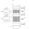
本発明は、以下に詳細に述べるように、各WORM使用可能なボリュームに対して次回書き込みポインタを管理するための装置、方法及びシステムを提供する。本発明によれば、図8に示すように、次回書き込みポインタ801はホストがボリューム802のどのディスクブロック番号にデータを書き込むことができるかを指示する。次回書き込みポインタ801によって指示されたディスクブロックが既に書き込み済み(読み出し専用領域803)の場合、次回書き込みポインタ801は、ホストによってデータが未だ書き込まれていない次のディスクブロック(読み出し及び書き込み領域804)を指示するように値が増やされる。更に本発明によれば書き込み要求によって指示されたディスクブロック番号が次回書き込みポインタ801によって指示されたディスクブロック番号よりも小さい場合、ホストの書き込み要求はストレージシステムによって無視されるか又はエラーメッセージが返送される。
The present invention provides an apparatus, method and system for managing the next write pointer for each WORM-enabled volume, as will be described in detail below. According to the present invention, as shown in FIG. 8, the
本発明は書き込み保護領域を管理するための別の装置、方法及びシステムも提供する。本発明によれば図9に示すように、書き込み保護領域901a、901bは、ストレージシステムのボリュームID、ボリューム903の書き込み保護領域901a、901bの先頭オフセット902a、902b及び末尾オフセット904a、904bを用いて特定される。本発明によってホストの書き込み要求は、この書き込み要求によって指示されたオフセットが読み出し及び書き込み領域905a、905b、905cでなく書き込み保護領域901a、901bの一つの中にある場合には、ストレージシステムにより無視されるか又はエラーメッセージが返送される。
The present invention also provides another apparatus, method and system for managing write protected areas. According to the present invention, as shown in FIG. 9, the
更に本発明によって二以上の書き込み保護領域は、これらの領域がボリューム上で連続した領域である場合は、一つの書き込み保護領域に結合される。そのような結合が行われる場合、結合される書き込み保護領域中の最長保存期間が結合した書き込み保護領域の保存期間に選ばれる。
本発明は以下に述べる種々の実施例を提供する。しかしながら、本発明はここで述べる実施例に限定されるものでなく、当業者に知られているか、当業者が知ることになるであろう他の実施例に拡張できることに注意願いたい。
Further, according to the present invention, two or more write protection areas are combined into one write protection area when these areas are continuous areas on the volume. When such a combination is performed, the longest storage period in the combined write protection area is selected as the storage period of the combined write protection area.
The present invention provides various embodiments described below. However, it should be noted that the present invention is not limited to the embodiments described herein, but can be extended to other embodiments known to those skilled in the art or that will be known to those skilled in the art.
本発明の第一の実施例として、図1に示すようにストレージシステム104、ホスト101aと101b、及び管理コンソール102を含むシステム構成が与えられる。
As a first embodiment of the present invention, a system configuration including a
ストレージシステムは、データが保存され取り出されるストレージ媒体上に展開される複数のボリューム109a、109b、109c、ストレージシステム104とホスト101a、101bとを接続するインタフェース105、ストレージシステム104を制御するディスクコントローラ106、一時的にデータを保存するキャッシュメモリ107、期間を計る内部タイマー110と、ボリュームがWORM使用可能かどうかに関する情報を保存するWORM構成テーブル108を含む。WORM構成テーブル108の詳細は以下に述べられる。
The storage system includes a plurality of
ディスクコントローラはインタフェース105を経由してホスト101a、101bのI/O要求を受信し、この要求を処理する。ディスクコントローラはキャッシュメモリ107とボリューム109a、109b、109cにアクセスする。キャッシュメモリ107はボリューム109a、109b、109cのデータ中のある部分をキャッシュしてアクセスを高速化している。内部タイマー110は相対時間を計り、それ自体ではその値を変更できない。
The disk controller receives the I / O request of the
ホスト101a、101bはアプリケーションを実行し、アプリケーションの要求に応じてリンク103a、103bを経由してストレージシステム内のボリューム109a、109b、109cに対してデータの読み出し/書き込みを行う。一般的にホスト101a、101bとストレージシステム104との間のリンク103a、103bにはFibreチャネル、FICON、SCSI、Ethernet(Ethernetは登録商標です)が用いられる。しかしながら、他のタイプのリンクも使用可能である。
The
管理コンソール102はリンク103cを経由してストレージシステム104と結合され、ストレージシステム104のWORM構成テーブル108の構成を含む管理機能を提供する。
The
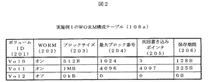
WORM構成テーブルの第一の実施例108aは、図2に示すようにストレージシステム104の各ボリュームに対して種々のエントリーを含んでいる。特に、WORM構成テーブルのエントリーは次回書き込みポインタを使用してボリュームの複数の領域のうちどれが書き込み保護されているかを示す。エントリーとして以下が挙げられる。
The first embodiment 108a of the WORM configuration table includes various entries for each volume of the
1)ボリュームID(201)。 1) Volume ID (201).
2)ボリュームがWORM使用可能かどうかを示すON/OFF表示(202)。 2) ON / OFF display (202) indicating whether the volume is WORM usable.
3)データが書き込み保護されているブロックのサイズの表示(203)。 3) Display of the size of the block in which the data is write protected (203).
4)ブロックの最大番号の表示(204)。(即ちボリューム容量はブロックサイズとブロックの最大番号の積に等しい。)
5)次回書き込みポインタ(205)。次回書き込みポインタはブロック番号を有しており、ホストが次回書き込みポインタによって指示されるブロック番号とボリュームの最大ブロック番号の間でデータを読み出し及び書き込むことができることを示す。一方ホストはブロック番号の始め即ち“0”と、次回書き込みポインタによって指示されるブロック番号マイナス1との間にはいかなるデータも書き込むことができない。図8は上述のように次回書き込みポインタを使用する例を示している。“Vol0”と名づけられたボリュームは0から1024までのディスクブロックを有しており、次回書き込みポインタは“3”を表示している。従ってブロック0とブロック2の間の領域は読み出し専用領域で、他の領域は読み出し及び書き込み領域となる。
4) Display of the maximum number of blocks (204). (That is, the volume capacity is equal to the product of the block size and the maximum block number.)
5) Next write pointer (205). The next write pointer has a block number, indicating that the host can read and write data between the block number indicated by the next write pointer and the maximum block number of the volume. On the other hand, the host cannot write any data between the beginning of the block number, that is, “0”, and the block number minus 1 indicated by the next write pointer. FIG. 8 shows an example in which the next write pointer is used as described above. The volume named “Vol0” has disk blocks from 0 to 1024, and the next write pointer displays “3”. Therefore, the area between
6)保存期間(206)。この期間はボリュームがデータで満たされた後、即ち次回書き込みポインタが最大ブロック番号プラス1を指示した後に、どの程度の期間ボリュームのデータを書き込み保護する必要があるかを示す。保存期間の値は一日に1ずつ減らされる。ストレージシステムは一日が過ぎたかどうかを判定するために内部タイマーを使用する。もし一層きめ細かな保存が求められる場合は、時間又は分、秒が単位として用いられ得る。 6) Storage period (206). This period indicates how long the volume data needs to be write protected after the volume is filled with data, that is, after the next write pointer indicates the maximum block number plus one. The retention period value is reduced by one per day. The storage system uses an internal timer to determine if the day has passed. If more detailed storage is required, hours or minutes and seconds can be used as units.
管理コンソール102とホスト101a、101bはWORM構成テーブル108aを構成することができる。ディスクコントローラはそれらが以下を構成することを可能にする。
The
1)指定されたボリュームに対するエントリーがWORM構成テーブルに存在しない場合のみ、このボリュームに対する新たなエントリーを生成する。 1) Create a new entry for this volume only if no entry for the specified volume exists in the WORM configuration table.
2)エントリーがWORM使用可能でない場合のみエントリーをWORM使用可能にする。 2) Make an entry WORM-enabled only if the entry is not WORM-enabled.
3)エントリーの保存期間が0の場合のみエントリーを削除する。 3) An entry is deleted only when the entry retention period is zero.
4)WORM構成テーブルのエントリーを読み出す。 4) Read an entry in the WORM configuration table.
図4は本発明によるWORM構成テーブルの第一の実施例108aを用いた書き込み要求処理の手順の第一の実施例を示すフローチャートである。具体的には図4のフローチャートは、ディスクコントローラ106がホスト101a、101bの書き込み要求を受信した場合にディスクコントローラ106が実行するプロセスを示す。
FIG. 4 is a flowchart showing a first embodiment of the write request processing procedure using the first embodiment 108a of the WORM configuration table according to the present invention. Specifically, the flowchart of FIG. 4 shows a process executed by the
書き込み要求を受信時、ディスクコントローラ106はWORM構成テーブル108aを用いて、書き込み要求が任意のWORM使用可能のボリュームに対するものであるかどうかをチェックする(ステップ401)。もし書き込み要求がWORM使用可能ボリュームに対するものであれば、プロセスはステップ402に進む。もし書き込み要求がWORM使用可能のボリュームに対するものでなければ、プロセスはステップ405に進む。ディスクコントローラ106は、書き込み要求によって指定されたオフセットがボリュームの次回書き込みポインタにより指示されたオフセットと等しい又はより大であるかどうかをチェックする(ステップ402)。もし書き込み要求によって指定されたオフセットがボリュームの次回書き込みポインタにより指示されたオフセットと等しい又はより大である場合は、プロセスはステップ403に進む。もし書き込み要求によって指定されたオフセットがボリュームの次回書き込みポインタにより指示されたオフセットより小の場合は、プロセスはステップ406に進む。ディスクコントローラ106は要求にあるデータを次回書き込みポインタにより指示されたディスクブロックに書き込む(ステップ403)。ディスクコントローラ106は次回書き込みポインタの値を1だけ増やし、この手順を終える(ステップ404)。ディスクコントローラ106は書き込み要求を処理してこの手順を終える(ステップ405)。ディスクコントローラ106は要求ホストにエラーメッセージを返送してこの手順を終える(ステップ406)。
When receiving a write request, the
図6は本発明によるWORM構成テーブルの第一の実施例108aを用いて保存期間を減少させる手順の第一の実施例を示すフローチャートである。 FIG. 6 is a flowchart showing a first embodiment of a procedure for reducing the retention period using the first embodiment 108a of the WORM configuration table according to the present invention.
本発明によればストレージシステム104の内部タイマー110は一日に一度ディスクコントローラ106に割り込みを送信する。このタイミングは1時間に一度、1分間に一度等のように変更可能である。あるいはディスクコントローラ106は前に内部タイマー110をチェックしてからどれくらい時間が経過したかを判定するために内部タイマー110をチェックする。ディスクコントローラ106が割り込みを受信するか一日が経過したかを問わずディスクコントローラ106は図6に示す手順を実行する。
According to the present invention, the
具体的には本発明によればディスクコントローラ106は、WORM構成テーブル108aの各エントリーに対して、次回書き込みポインタの値が最大ブロック番号よりも大きい(即ちボリュームがファイルによって満たされた)かどうかをチェックする(ステップ601)。もし次回書き込みポインタの値が最大ブロック番号よりも大きい場合にはプロセスはステップ602に進む。もしWORM構成テーブルにそのようなエントリーが存在しない場合はプロセスは手順を終了する。もし次回書き込みポインタの値が最大ブロック番号よりも大きい場合にはディスクコントローラ106は保存期間の値を一日だけ減少させる(ステップ602)。次いでディスクコントローラ106は、保存期間の値が0かどうかチェックする(ステップ603)。もし保存期間の値が0であればプロセスはステップ604に進む。もし保存期間の値が0でなければ、プロセスはステップ601に戻る。ステップ604で、ディスクコントローラ106はエントリーに対してWORM使用可能から不能に切り換える(即ちボリュームのデータに対する保存期間が満了したことになる)。その後プロセスはステップ601に戻る。
Specifically, according to the present invention, the
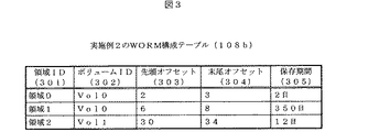
本発明の第二の実施例として、図1に示す第一の実施例と同様に、ストレージシステム104、ホスト101aと101b、及び管理コンソール102を含むシステム構成が与えられる。第一と第二の実施例間の相違の一つはWORM構成テーブルにある。第二の実施例は図3に示すWORM構成テーブル108bを備えており、この構成テーブルはストレージシステム104の各ボリュームに対する種々のエントリーを含んでいる。これらのエントリーとして以下が挙げられる。
As a second embodiment of the present invention, a system configuration including a
1)書き込み保護領域のIDを示す領域ID(301)。 1) Area ID (301) indicating the ID of the write protection area.
2)保護領域が含まれるボリュームID(302)。 2) Volume ID (302) including the protection area.
3)ボリュームの書き込み保護領域が開始するオフセットを示す先頭オフセット(303)。 3) A head offset (303) indicating an offset at which the write protection area of the volume starts.
4)ボリュームの書き込み保護領域が終了するオフセットを示す末尾オフセット(304)。 4) A tail offset (304) indicating an offset at which the write protection area of the volume ends.
5)書き込み保護領域にどれくらいの期間データを読み出し専用に維持しなければならないかを示す保存期間(305)。 5) A retention period (305) indicating how long data must be kept read-only in the write protected area.
図9はボリューム“Vol0”内の書き込み保護領域の例を示す。“領域0”と“領域1”の二つの領域が存在する。書き込み保護領域によって指定される任意の領域は書き込み不可である。他の領域は読み出し及び書き込み領域である。
FIG. 9 shows an example of the write protection area in the volume “Vol0”. There are two areas, “
管理コンソールとホストはWORM構成テーブル108bを構成することができる。ディスクコントローラ106は以下を構成することを可能にする。
The management console and the host can configure the WORM configuration table 108b. The
1)新たなエントリーとWORM構成テーブルのエントリー間にオフセットのオーバラップが存在しない場合のみ、新たな書き込み保護領域を生成する。 1) A new write protection area is generated only when there is no offset overlap between the new entry and the WORM configuration table entry.
2)新たな保存期間が現時点の保存期間よりも長期の場合のみ保存期間を延長する。 2) Extend the storage period only when the new storage period is longer than the current storage period.
3)エントリーの保存期間が0の場合のみエントリーを削除する。 3) An entry is deleted only when the entry retention period is zero.
4)WORM構成テーブルのエントリーを読み出す。 4) Read an entry in the WORM configuration table.
5)二以上の保護領域が連続している場合のみ、これらを一つの保護領域に結合する。これらの領域の最長保存期間が結合した書き込み保護領域に対して選ばれる。 5) Only when two or more protection areas are continuous, these are combined into one protection area. The longest storage period of these areas is chosen for the combined write protection area.
図5は本発明によるWORM構成テーブルの第二の実施例108bを用いた書き込み要求処理の手順の第二の実施例を示すフローチャートである。具体的には図5のフローチャートは、ディスクコントローラ106がホスト101a、101bの書き込み要求を受信した場合にディスクコントローラ106が実行するプロセスを示す。書き込み要求を受信時、ディスクコントローラ106はTopを含む一時的な値を設定する。ここでTop=書き込み要求で指定されたオフセット、Bottom=Top+書き込み要求にあるデータのサイズ、である(ステップ501)。ディスクコントローラ106は0よりも大きな保存期間を有するWORM構成テーブル108bの各書き込み保護領域に対して、書き込み要求が書き込み保護領域で指定されるボリュームに対するものであるかどうかをチェックする(ステップ502)。もし書き込み要求が書き込み保護領域で指定されるボリュームに対するものであれば、プロセスはステップ503に進む。もし書き込み要求が書き込み保護領域で指定されるボリュームに対するものでない場合は、プロセスはステップ504に進む。ディスクコントローラ106は、書き込み保護領域に対して次の条件のうち一つが満たされるかどうか(即ち書き込もうとする領域と書き込み保護領域の間にオーバラップが存在するか)をチェックする;(1)先頭オフセット≦Top≦末尾オフセット(2)先頭オフセット≦Bottom≦末尾オフセット(ステップ503)。書き込もうとする領域と書き込み保護領域との間にオーバラップが存在する場合には、プロセスはステップ505に進む。書き込もうとする領域と書き込み保護領域との間にオーバラップが存在しない場合には、プロセスはステップ502に進み、別の領域をチェックする。次いでディスクコントローラ106は書き込み要求を処理する(ステップ504)。ステップ505で、ディスクコントローラ106は要求ホストにエラーメッセージを返送する。
FIG. 5 is a flowchart showing a second embodiment of the write request processing procedure using the second embodiment 108b of the WORM configuration table according to the present invention. Specifically, the flowchart of FIG. 5 shows a process executed by the
図7は本発明によるWORM構成テーブルの第二の実施例108bを用いて保存期間を減少させる手順の第二の実施例を示すフローチャートである。 FIG. 7 is a flowchart showing a second embodiment of the procedure for reducing the retention period using the second embodiment 108b of the WORM configuration table according to the present invention.
本発明によればストレージシステム104の内部タイマー110は一日に一度ディスクコントローラ106に割り込みを送信する。このタイミングは1時間に一度、1分間に一度等のように変更可能である。あるいはディスクコントローラ106は前に内部タイマー110をチェックしてからどれくらい時間が経過したかを判定するために内部タイマー110をチェックする。ディスクコントローラ106が割り込みを受信するか一日が経過したかを問わずディスクコントローラ106は図7に示す手順を実行する。
According to the present invention, the
具体的には、本発明によれば、WORM構成テーブル108bの各エントリーに対して、ディスクコントローラ106はエントリーの保存期間の値が0よりも大きいかどうかをチェックする(ステップ701)。もしエントリーの保存期間の値が0よりも大きい場合には、プロセスはステップ702に進む。もしエントリーの保存期間の値が0より大きくない場合は、プロセスは手順を終了する。ステップ702で、ディスクコントローラ106は保存期間の値を一日だけ減少させる。
本発明は好適な実施例の観点から述べられてきたが、本発明の精神と範囲から逸脱することなく数多くの変形例が可能であることは明らかであろう。このようなすべての変形例は添付する特許請求の範囲に含まれるものと意図される。
Specifically, according to the present invention, for each entry in the WORM configuration table 108b, the
While the invention has been described in terms of a preferred embodiment, it will be apparent that many variations are possible without departing from the spirit and scope of the invention. All such modifications are intended to be included within the scope of the appended claims.
それぞれ本発明の開示の一部を構成する付随する図面と関連して読めば、実施例の詳細な説明及び特許請求の範囲によって、本発明に関して前述してきたことが理解でき、一層理解が明快になるであろう。前述及び以下の記述および図示は本発明の実施例を開示することに焦点を合わせているが、これは単に説明及び例示としてなされるものであり、本発明はこれらに限定されるものでないことを明快に理解願いたい。この意味に於いて以下に図面の簡単な説明を示す。 When read in conjunction with the accompanying drawings, each forming a part of the disclosure of the present invention, the detailed description of the embodiments and the claims can be understood and understood more clearly with respect to the present invention. It will be. The foregoing and following description and illustrations focus on disclosing examples of the present invention, but this is merely illustrative and exemplary and the present invention is not limited thereto. Please understand clearly. In this sense, the following is a brief description of the drawings.
101a ホストA
101b ホストB
102 管理コンソール
104 ストレージシステム
105 インタフェース
106 ディスクコントローラ
107 キャッシュメモリ
108 WORM構成テーブル
109a ボリューム“Vol0”
109b ボリューム“Vol1”
109c ボリューム“Vol2”
110 内部タイマー
201 ボリュームID、Vol0、Vol1、Vol2
202 WORM、オン、オン、オフ
203 ブロックサイズ、512B、1MB、0kB
204 最大ブロック番号
205 次回書き込みポインタ
206 保存期間、128日、325日、0日
101a Host A
101b Host B
102
109b Volume “Vol1”
109c Volume “Vol2”
110
202 WORM, ON, ON, OFF 203 Block size, 512B, 1MB, 0kB
204
Claims (17)
ストレージシステムを制御するディスクコントローラと、
次回書き込みポインタの使用により前記ボリュームの複数の領域のどれが書き込み保護されているかを表示する複数のエントリーを有するWORM(追記型)構成テーブルと、を有することを特徴とする、ストレージシステムのボリュームに保存されるデータを保護するためのストレージシステム。 A storage medium on which the volume is expanded; and
A disk controller to control the storage system;
A volume of the storage system, comprising: a WORM (write-once) configuration table having a plurality of entries indicating which of the plurality of areas of the volume is write-protected by use of a next write pointer A storage system for protecting stored data.
前記ボリュームのブロック番号は該ボリュームの第一のストレージ位置に対応して0で始まり、該ボリュームの最後のストレージ位置に到達するまで1ずつ増加する、
ことを特徴とする、請求項1のストレージシステム。 Each of the areas is a storage block of the volume that can be specified by a block number,
The block number of the volume starts with 0 corresponding to the first storage location of the volume and increases by 1 until the last storage location of the volume is reached,
The storage system according to claim 1, wherein:
前記次回書き込みポインタは該次回書き込みポインタの該ブロック番号よりも小さいブロック番号を有するブロックにデータを書き込むことができないことを示す、
ことを特徴とする、請求項5のストレージシステム。 The next write pointer has a block number of a storage location where data can be written,
The next write pointer indicates that data cannot be written to a block having a block number smaller than the block number of the next write pointer.
The storage system according to claim 5, wherein:
ストレージシステムを制御するディスクコントローラと、
各々が先頭オフセットと末尾オフセットを用いて定義される前記ボリュームの書き込み保護された領域を表示する複数のエントリーを有するWORM(追記型)構成テーブルと、
を有することを特徴とする、ストレージシステムのボリュームに保存されるデータを保護するためのストレージシステム。 A storage medium on which the volume is expanded; and
A disk controller to control the storage system;
A WORM (write-once) configuration table having a plurality of entries each displaying a write protected area of the volume defined using a head offset and a tail offset;
A storage system for protecting data stored in a volume of the storage system.
前記ボリュームの各ブロックはブロック番号で特定可能であり、
前記ボリュームのブロック番号は該ボリュームの第一のストレージ位置に対応して0で始まり、該ボリュームの最後のストレージ位置に到達するまで1ずつ増加すること、
を特徴とする、請求項11のストレージシステム。 The volume includes a plurality of blocks, and at least one of the blocks is included in each area.
Each block of the volume can be identified by a block number,
The block number of the volume starts at 0 corresponding to the first storage location of the volume and increments by 1 until the last storage location of the volume is reached;
The storage system according to claim 11, wherein:
前記先頭及び末尾オフセットの間のブロック番号に対応するブロックにはデータを書き込むことができない、
ことを特徴とする、請求項12のストレージシステム。 The head offset has a block number of the storage position where the write protection area starts, and the tail offset has a block number of the storage position at the end of the write protection area;
Data cannot be written to the block corresponding to the block number between the start and end offsets,
The storage system according to claim 12, wherein:
The disk controller, in response to a write request from a host, checks whether an offset specified by the write request is smaller than the head offset or larger than the tail offset. Item 12. The storage system according to Item 11.
Applications Claiming Priority (1)
| Application Number | Priority Date | Filing Date | Title |
|---|---|---|---|
| US10/800,737 US7162602B2 (en) | 2004-03-16 | 2004-03-16 | More granular and more efficient write protection for disk volumes |
Publications (2)
| Publication Number | Publication Date |
|---|---|
| JP2005267602A true JP2005267602A (en) | 2005-09-29 |
| JP2005267602A5 JP2005267602A5 (en) | 2007-10-18 |
Family
ID=34987708
Family Applications (1)
| Application Number | Title | Priority Date | Filing Date |
|---|---|---|---|
| JP2004307581A Withdrawn JP2005267602A (en) | 2004-03-16 | 2004-10-22 | Further fine and efficient write protection for disk volume |
Country Status (2)
| Country | Link |
|---|---|
| US (1) | US7162602B2 (en) |
| JP (1) | JP2005267602A (en) |
Cited By (5)
| Publication number | Priority date | Publication date | Assignee | Title |
|---|---|---|---|---|
| JP2007183703A (en) * | 2006-01-04 | 2007-07-19 | Hitachi Ltd | Storage device preventing falsification of data |
| US7571350B2 (en) | 2006-02-14 | 2009-08-04 | Hitachi, Ltd. | Storage system and recovery method thereof |
| US7685390B2 (en) | 2006-11-02 | 2010-03-23 | Hitachi, Ltd. | Storage system |
| US8046531B2 (en) | 2009-03-10 | 2011-10-25 | Hitachi, Ltd. | Storage apparatus, management apparatus, and method of controlling storage apparatus |
| KR20180040178A (en) * | 2016-10-11 | 2018-04-20 | 임장식 | Method for preventing real-time alteration of the data in WORM storage device based on hard disk or SSD |
Families Citing this family (12)
| Publication number | Priority date | Publication date | Assignee | Title |
|---|---|---|---|---|
| US7337360B2 (en) | 1999-10-19 | 2008-02-26 | Idocrase Investments Llc | Stored memory recovery system |
| US6594780B1 (en) | 1999-10-19 | 2003-07-15 | Inasoft, Inc. | Operating system and data protection |
| JP4624732B2 (en) * | 2003-07-16 | 2011-02-02 | パナソニック株式会社 | how to access |
| JP2006127106A (en) * | 2004-10-28 | 2006-05-18 | Hitachi Ltd | Storage system and its control method |
| GB0511919D0 (en) * | 2005-06-11 | 2005-07-20 | Ibm | Device permitting partial disabling of information retrievability on worm media |
| US7265928B2 (en) * | 2006-01-24 | 2007-09-04 | Imation Corp. | Data storage cartridge with worm write-protection |
| JP4800046B2 (en) * | 2006-01-31 | 2011-10-26 | 株式会社日立製作所 | Storage system |
| JP2008009485A (en) * | 2006-06-27 | 2008-01-17 | Fujitsu Ltd | Virtual storage controller and virtual storage control program |
| DE102006052173B4 (en) | 2006-11-02 | 2023-06-01 | Fast Lta Gmbh | Write protection method and apparatus for at least one random access memory device |
| US8413253B2 (en) * | 2009-12-30 | 2013-04-02 | Intel Corporation | Protecting persistent secondary platform storage against attack from malicious or unauthorized programs |
| CN102184143B (en) * | 2011-04-25 | 2013-08-14 | 深圳市江波龙电子有限公司 | Data protection method, device and system for storage device |
| US11086797B2 (en) * | 2014-10-31 | 2021-08-10 | Hewlett Packard Enterprise Development Lp | Systems and methods for restricting write access to non-volatile memory |
Family Cites Families (14)
| Publication number | Priority date | Publication date | Assignee | Title |
|---|---|---|---|---|
| US18878A (en) * | 1857-12-15 | Curtain-eixttjbe | ||
| US4974156A (en) * | 1988-05-05 | 1990-11-27 | International Business Machines | Multi-level peripheral data storage hierarchy with independent access to all levels of the hierarchy |
| EP0389399A3 (en) * | 1989-03-20 | 1993-01-20 | International Business Machines Corporation | Directory structure for worm optical media |
| US5491807A (en) * | 1989-03-20 | 1996-02-13 | International Business Machines Corporation | System and method for worm volume management of new and updated data files using variable threshold block addresses |
| US5247658A (en) | 1989-10-31 | 1993-09-21 | Microsoft Corporation | Method and system for traversing linked list record based upon write-once predetermined bit value of secondary pointers |
| US5043967A (en) * | 1990-08-20 | 1991-08-27 | International Business Machines Corporation | Structured data storage method and medium |
| US5321824A (en) * | 1991-04-22 | 1994-06-14 | International Business Machines Corporation | Accessing last recorded data in a continuation chain |
| US5790848A (en) * | 1995-02-03 | 1998-08-04 | Dex Information Systems, Inc. | Method and apparatus for data access and update in a shared file environment |
| US7392234B2 (en) * | 1999-05-18 | 2008-06-24 | Kom, Inc. | Method and system for electronic file lifecycle management |
| US6370534B1 (en) * | 1999-06-01 | 2002-04-09 | Pliant Technologies, Inc. | Blocking techniques for data storage |
| US6542971B1 (en) * | 2001-04-23 | 2003-04-01 | Nvidia Corporation | Memory access system and method employing an auxiliary buffer |
| US6912645B2 (en) | 2001-07-19 | 2005-06-28 | Lucent Technologies Inc. | Method and apparatus for archival data storage |
| JP4058322B2 (en) * | 2002-10-07 | 2008-03-05 | 株式会社ルネサステクノロジ | Memory card |
| US20040220959A1 (en) * | 2003-04-30 | 2004-11-04 | Rothman Michael A | Methods and apparatus to enable system configuration during operating system runtime |
-
2004
- 2004-03-16 US US10/800,737 patent/US7162602B2/en not_active Expired - Fee Related
- 2004-10-22 JP JP2004307581A patent/JP2005267602A/en not_active Withdrawn
Cited By (6)
| Publication number | Priority date | Publication date | Assignee | Title |
|---|---|---|---|---|
| JP2007183703A (en) * | 2006-01-04 | 2007-07-19 | Hitachi Ltd | Storage device preventing falsification of data |
| US7571350B2 (en) | 2006-02-14 | 2009-08-04 | Hitachi, Ltd. | Storage system and recovery method thereof |
| US7685390B2 (en) | 2006-11-02 | 2010-03-23 | Hitachi, Ltd. | Storage system |
| US8046531B2 (en) | 2009-03-10 | 2011-10-25 | Hitachi, Ltd. | Storage apparatus, management apparatus, and method of controlling storage apparatus |
| KR20180040178A (en) * | 2016-10-11 | 2018-04-20 | 임장식 | Method for preventing real-time alteration of the data in WORM storage device based on hard disk or SSD |
| KR101954421B1 (en) * | 2016-10-11 | 2019-03-06 | 임장식 | Method for preventing real-time alteration of the data in WORM storage device based on hard disk or SSD |
Also Published As
| Publication number | Publication date |
|---|---|
| US20050210211A1 (en) | 2005-09-22 |
| US7162602B2 (en) | 2007-01-09 |
Similar Documents
| Publication | Publication Date | Title |
|---|---|---|
| JP4486348B2 (en) | Disk array that suppresses drive operating time | |
| US20090100223A1 (en) | Storage control apparatus, data archive method for storage control apparatus, and storage system | |
| KR100962883B1 (en) | Method, system, and program for migrating source data to target data | |
| JP2005267602A (en) | Further fine and efficient write protection for disk volume | |
| US8635419B2 (en) | Methods for implementation of worm mode on a removable storage system | |
| JP4843604B2 (en) | Method and system for obtaining data storage device specific information from data storage device | |
| US20090157756A1 (en) | File System For Storing Files In Multiple Different Data Storage Media | |
| US6564307B1 (en) | Method, system, and program for logically erasing data | |
| US6205529B1 (en) | Method and apparatus for defragmenting a storage device using a copy function in the device control logic | |
| US6425050B1 (en) | Method, system, and program for performing read operations during a destage operation | |
| US7987328B2 (en) | Data archive system | |
| JP2006072789A (en) | Storage system and data management device of the same | |
| JP2008269331A (en) | Device driver | |
| JP2006004408A (en) | Data protection method of disk array system | |
| WO2007044250A2 (en) | Computer storage device providing implicit detection of block liveness | |
| US20180024742A1 (en) | Storage media performance management | |
| JP4713951B2 (en) | Virtual tape library system and virtual tape writing method | |
| JP2006338345A5 (en) | ||
| US6792517B1 (en) | Firmware controlled backup in disk drives | |
| US8688938B2 (en) | Data copying | |
| JP2005267599A (en) | Storage area network and data write protection in coexisting environment of network attached storage | |
| JP2005284816A (en) | Disk array system | |
| JPH08221210A (en) | Disk controller | |
| JP2005301862A (en) | Disk recording device, monitoring method and monitoring program of disk recording medium | |
| JPH08161123A (en) | Disk array device |
Legal Events
| Date | Code | Title | Description |
|---|---|---|---|
| RD04 | Notification of resignation of power of attorney |
Free format text: JAPANESE INTERMEDIATE CODE: A7424 Effective date: 20060425 |
|
| A521 | Request for written amendment filed |
Free format text: JAPANESE INTERMEDIATE CODE: A523 Effective date: 20070905 |
|
| A621 | Written request for application examination |
Free format text: JAPANESE INTERMEDIATE CODE: A621 Effective date: 20070905 |
|
| RD03 | Notification of appointment of power of attorney |
Free format text: JAPANESE INTERMEDIATE CODE: A7423 Effective date: 20070905 |
|
| RD04 | Notification of resignation of power of attorney |
Free format text: JAPANESE INTERMEDIATE CODE: A7424 Effective date: 20071003 |
|
| RD04 | Notification of resignation of power of attorney |
Free format text: JAPANESE INTERMEDIATE CODE: A7424 Effective date: 20090212 |
|
| A761 | Written withdrawal of application |
Free format text: JAPANESE INTERMEDIATE CODE: A761 Effective date: 20090527 |