JP2005247272A - Air bag apparatus - Google Patents
Air bag apparatus Download PDFInfo
- Publication number
- JP2005247272A JP2005247272A JP2004064555A JP2004064555A JP2005247272A JP 2005247272 A JP2005247272 A JP 2005247272A JP 2004064555 A JP2004064555 A JP 2004064555A JP 2004064555 A JP2004064555 A JP 2004064555A JP 2005247272 A JP2005247272 A JP 2005247272A
- Authority
- JP
- Japan
- Prior art keywords
- gas
- airbag
- inflator
- chamber
- air bag
- Prior art date
- Legal status (The legal status is an assumption and is not a legal conclusion. Google has not performed a legal analysis and makes no representation as to the accuracy of the status listed.)
- Withdrawn
Links
Images


Classifications
-
- B—PERFORMING OPERATIONS; TRANSPORTING
- B60—VEHICLES IN GENERAL
- B60R—VEHICLES, VEHICLE FITTINGS, OR VEHICLE PARTS, NOT OTHERWISE PROVIDED FOR
- B60R21/00—Arrangements or fittings on vehicles for protecting or preventing injuries to occupants or pedestrians in case of accidents or other traffic risks
- B60R21/02—Occupant safety arrangements or fittings, e.g. crash pads
- B60R21/16—Inflatable occupant restraints or confinements designed to inflate upon impact or impending impact, e.g. air bags
- B60R21/23—Inflatable members
- B60R21/231—Inflatable members characterised by their shape, construction or spatial configuration
- B60R21/233—Inflatable members characterised by their shape, construction or spatial configuration comprising a plurality of individual compartments; comprising two or more bag-like members, one within the other
-
- B—PERFORMING OPERATIONS; TRANSPORTING
- B60—VEHICLES IN GENERAL
- B60R—VEHICLES, VEHICLE FITTINGS, OR VEHICLE PARTS, NOT OTHERWISE PROVIDED FOR
- B60R21/00—Arrangements or fittings on vehicles for protecting or preventing injuries to occupants or pedestrians in case of accidents or other traffic risks
- B60R21/02—Occupant safety arrangements or fittings, e.g. crash pads
- B60R21/16—Inflatable occupant restraints or confinements designed to inflate upon impact or impending impact, e.g. air bags
- B60R21/26—Inflatable occupant restraints or confinements designed to inflate upon impact or impending impact, e.g. air bags characterised by the inflation fluid source or means to control inflation fluid flow
- B60R21/261—Inflatable occupant restraints or confinements designed to inflate upon impact or impending impact, e.g. air bags characterised by the inflation fluid source or means to control inflation fluid flow with means other than bag structure to diffuse or guide inflation fluid
-
- B—PERFORMING OPERATIONS; TRANSPORTING
- B60—VEHICLES IN GENERAL
- B60R—VEHICLES, VEHICLE FITTINGS, OR VEHICLE PARTS, NOT OTHERWISE PROVIDED FOR
- B60R21/00—Arrangements or fittings on vehicles for protecting or preventing injuries to occupants or pedestrians in case of accidents or other traffic risks
- B60R21/02—Occupant safety arrangements or fittings, e.g. crash pads
- B60R21/16—Inflatable occupant restraints or confinements designed to inflate upon impact or impending impact, e.g. air bags
- B60R21/23—Inflatable members
- B60R21/231—Inflatable members characterised by their shape, construction or spatial configuration
- B60R21/233—Inflatable members characterised by their shape, construction or spatial configuration comprising a plurality of individual compartments; comprising two or more bag-like members, one within the other
- B60R2021/23324—Inner walls crating separate compartments, e.g. communicating with vents
-
- B—PERFORMING OPERATIONS; TRANSPORTING
- B60—VEHICLES IN GENERAL
- B60R—VEHICLES, VEHICLE FITTINGS, OR VEHICLE PARTS, NOT OTHERWISE PROVIDED FOR
- B60R21/00—Arrangements or fittings on vehicles for protecting or preventing injuries to occupants or pedestrians in case of accidents or other traffic risks
- B60R21/02—Occupant safety arrangements or fittings, e.g. crash pads
- B60R21/16—Inflatable occupant restraints or confinements designed to inflate upon impact or impending impact, e.g. air bags
- B60R21/26—Inflatable occupant restraints or confinements designed to inflate upon impact or impending impact, e.g. air bags characterised by the inflation fluid source or means to control inflation fluid flow
- B60R2021/26058—Inflatable occupant restraints or confinements designed to inflate upon impact or impending impact, e.g. air bags characterised by the inflation fluid source or means to control inflation fluid flow using a combination of inflators
-
- B—PERFORMING OPERATIONS; TRANSPORTING
- B60—VEHICLES IN GENERAL
- B60R—VEHICLES, VEHICLE FITTINGS, OR VEHICLE PARTS, NOT OTHERWISE PROVIDED FOR
- B60R21/00—Arrangements or fittings on vehicles for protecting or preventing injuries to occupants or pedestrians in case of accidents or other traffic risks
- B60R21/02—Occupant safety arrangements or fittings, e.g. crash pads
- B60R21/16—Inflatable occupant restraints or confinements designed to inflate upon impact or impending impact, e.g. air bags
- B60R21/26—Inflatable occupant restraints or confinements designed to inflate upon impact or impending impact, e.g. air bags characterised by the inflation fluid source or means to control inflation fluid flow
- B60R21/263—Inflatable occupant restraints or confinements designed to inflate upon impact or impending impact, e.g. air bags characterised by the inflation fluid source or means to control inflation fluid flow using a variable source, e.g. plural stage or controlled output
- B60R2021/2633—Inflatable occupant restraints or confinements designed to inflate upon impact or impending impact, e.g. air bags characterised by the inflation fluid source or means to control inflation fluid flow using a variable source, e.g. plural stage or controlled output with a plurality of inflation levels
-
- B—PERFORMING OPERATIONS; TRANSPORTING
- B60—VEHICLES IN GENERAL
- B60R—VEHICLES, VEHICLE FITTINGS, OR VEHICLE PARTS, NOT OTHERWISE PROVIDED FOR
- B60R21/00—Arrangements or fittings on vehicles for protecting or preventing injuries to occupants or pedestrians in case of accidents or other traffic risks
- B60R21/02—Occupant safety arrangements or fittings, e.g. crash pads
- B60R21/16—Inflatable occupant restraints or confinements designed to inflate upon impact or impending impact, e.g. air bags
- B60R21/20—Arrangements for storing inflatable members in their non-use or deflated condition; Arrangement or mounting of air bag modules or components
- B60R21/217—Inflation fluid source retainers, e.g. reaction canisters; Connection of bags, covers, diffusers or inflation fluid sources therewith or together
Landscapes
- Engineering & Computer Science (AREA)
- Mechanical Engineering (AREA)
- Physics & Mathematics (AREA)
- Fluid Mechanics (AREA)
- Air Bags (AREA)
Abstract
Description
本発明は、自動車等に設置されるエアバッグ装置に関するものである。 The present invention relates to an airbag device installed in an automobile or the like.
自動車等に設置されるエアバッグ装置は、エアバッグと、このエアバッグを膨張させるインフレータとを有している。 An airbag device installed in an automobile or the like includes an airbag and an inflator that inflates the airbag.
車両の衝突がセンサによって検知されると、インフレータが作動し、インフレータから発生したガスによってエアバッグが膨張する。 When the collision of the vehicle is detected by the sensor, the inflator is activated and the airbag is inflated by the gas generated from the inflator.
特開平2−74440号公報には、運転席用エアバッグ内を区画用パネルによって中央の室と外周側の2室とに区画し、まず中央の室を膨張させ、次いで外周の室を膨張させるようにしたエアバッグが記載されている。この区画用のパネルにガス流通用の透口が設けられている。この区画用パネルは、エアバッグの後部側と前部側とをつないでおり、エアバッグが膨張時に前方に突出することを防止する機能を有している。 In Japanese Patent Laid-Open No. 2-74440, a driver's seat airbag is partitioned into a central chamber and two outer peripheral chambers by a partition panel, the central chamber is first inflated, and then the outer peripheral chamber is inflated. An airbag as described is described. The partition panel is provided with a gas distribution through hole. This partitioning panel connects the rear side and the front side of the airbag, and has a function of preventing the airbag from protruding forward when inflated.
米国特許6,254,121号には、これとは逆に、まず外周側の室を膨張させ、次いで中央の室を膨張させるよう構成した運転席用エアバッグ装置が記載されている。 U.S. Pat. No. 6,254,121, on the contrary, describes a driver's seat airbag apparatus configured to first inflate the outer peripheral chamber and then inflate the central chamber.
上記いずれのエアバッグ装置においても、インフレータは1個のみ設けられている。前者の特開平2−74440号では、インフレータは中央の室にガスを噴出させるよう設置されており、後者の米国特許6,254,121号では、インフレータは外周の室にガスを噴出させるように設置されている。
上記従来のエアバッグ装置は、中央の室及び外周の室の膨張する順番を制御することはできるが、各室の内圧を個別に制御することはできない。 The conventional airbag apparatus can control the order of expansion of the central chamber and the outer peripheral chamber, but cannot control the internal pressure of each chamber individually.
本発明は、複数の室を有するエアバッグを備えたエアバッグ装置;あるいは、複数のエアバッグを備えたエアバッグ装置において、各室又は各エアバッグの膨張する順番だけでなく、膨張時の内圧も個別に制御するよう構成することが可能なエアバッグ装置を提供することを目的とする。 The present invention relates to an airbag device including an airbag having a plurality of chambers; or, in an airbag device including a plurality of airbags, not only the order in which each chamber or each airbag is inflated, but also the internal pressure during inflation. It is another object of the present invention to provide an airbag device that can be individually controlled.
本発明(請求項1)のエアバッグ装置は、複数の室を有したエアバッグと、このエアバッグを膨張させるガス発生手段とを有するエアバッグ装置において、少なくとも一部の室へのガス発生手段からのガス供給が他の室へのガス発生手段からのガス供給と独立して制御可能であることを特徴とするものである。 An airbag apparatus of the present invention (Claim 1) is an airbag apparatus having an airbag having a plurality of chambers and a gas generating means for inflating the airbag, and a gas generating means for at least some of the chambers. The gas supply from can be controlled independently of the gas supply from the gas generating means to the other chambers.
請求項2のエアバッグ装置は、請求項1において、該ガス発生手段は複数の独立してガス発生動作可能なガス発生部を有したインフレータよりなり、各ガス発生部からのガスがそれぞれ別の室へ供給されることを特徴とするものである。 According to a second aspect of the present invention, there is provided an airbag device according to the first aspect, wherein the gas generating means comprises an inflator having a plurality of gas generating units capable of independently generating gas, and the gas from each gas generating unit is different. It is supplied to the chamber.
請求項3のエアバッグ装置は、請求項1において、該ガス発生手段は複数の独立してガス発生動作可能なインフレータよりなり、各インフレータからのガスがそれぞれ別の室へ供給されることを特徴とするものである。 According to a third aspect of the present invention, in the air bag apparatus according to the first aspect, the gas generating means comprises a plurality of inflators capable of independently generating gas, and the gas from each inflator is supplied to separate chambers. It is what.
本発明(請求項4)のエアバッグ装置は、複数のエアバッグと、各エアバッグを膨張させるガス発生手段とを有するエアバッグ装置であって、少なくとも一部のエアバッグへのガス発生手段からのガス供給が他のエアバッグへのガス発生手段からのガス供給と独立して制御可能であることを特徴とするものである。 The airbag device of the present invention (Claim 4) is an airbag device having a plurality of airbags and gas generating means for inflating each airbag, and includes at least a part of the gas generating means for the airbag. The gas supply can be controlled independently of the gas supply from the gas generating means to the other airbags.
請求項5のエアバッグ装置は、請求項4において、該ガス発生手段は複数の独立してガス発生動作可能なガス発生部を有したインフレータよりなり、各ガス発生部からのガスがそれぞれ別のエアバッグへ供給されることを特徴とするものである。 According to a fifth aspect of the present invention, there is provided an airbag device according to the fourth aspect, wherein the gas generating means comprises an inflator having a plurality of gas generating units capable of independently generating gas, and the gas from each gas generating unit is different. It is supplied to an airbag.
請求項6のエアバッグ装置は、請求項4において、該ガス発生手段として複数の独立してガス発生動作可能なインフレータよりなり、各インフレータからのガスがそれぞれ別のエアバッグへ供給されることを特徴とするものである。 The air bag device according to claim 6 is the air bag device according to claim 4, wherein the gas generating means includes a plurality of inflators capable of independently generating gas, and the gas from each inflator is supplied to a separate air bag. It is a feature.
請求項1のエアバッグ装置にあっては、エアバッグ内の複数の室のうちの少なくとも一部の室へのガス発生手段からのガス供給と他の室へのガス供給とがそれぞれ独立して制御可能であるので、各ガス発生手段の作動開始時期や出力を個別に制御することにより、エアバッグ内の各室が膨張する順番だけでなく、各室の膨張時の内圧も個別に制御することができる。 In the airbag device according to claim 1, the gas supply from the gas generation means to at least some of the plurality of chambers in the airbag and the gas supply to the other chambers are independent of each other. Since it is controllable, by controlling the operation start timing and output of each gas generating means individually, not only the order in which the chambers in the airbag are inflated, but also the internal pressure when each chamber is inflated is individually controlled. be able to.
請求項4のエアバッグ装置によると、複数のエアバッグが設けられている場合でも、そのうちの少なくとも一部のエアバッグへのガス発生手段からのガス供給が他のエアバッグへのガス供給と独立して制御可能であるので、各ガス発生手段の作動開始時期や出力を個別に制御することにより、各エアバッグが膨張する順番だけでなく、各エアバッグの膨張時の内圧も個別に制御することができる。 According to the airbag device of claim 4, even when a plurality of airbags are provided, the gas supply from the gas generating means to at least some of the airbags is independent of the gas supply to the other airbags. Therefore, by controlling the operation start timing and output of each gas generating means individually, not only the order in which each airbag is inflated, but also the internal pressure when each airbag is inflated is individually controlled. be able to.
本発明において、ガス発生手段は、複数の独立してガス発生動作可能なガス発生部を有したインフレータよりなり、各ガス発生部からのガスがそれぞれ別の室又はエアバッグへ供給されるよう構成されたものであってもよく、複数の独立してガス発生動作可能なインフレータよりなり、各インフレータからのガスがそれぞれ別の室又はエアバッグへ供給されるよう構成されたものであってもよい。 In the present invention, the gas generating means is composed of an inflator having a plurality of gas generating units capable of independently generating gas, and the gas from each gas generating unit is supplied to a separate chamber or airbag, respectively. It may be configured by a plurality of inflators capable of independently generating gas and configured to supply gas from each inflator to a separate chamber or airbag. .
ガス発生手段が複数の独立してガス発生動作可能なガス発生部を有したインフレータにより構成されている場合、1個のインフレータから複数の室又はエアバッグにそれぞれガス供給可能であるので、エアバッグ装置の構成部材点数が低減される。 When the gas generating means is constituted by an inflator having a plurality of gas generating units capable of independently generating gas, gas can be supplied from one inflator to each of a plurality of chambers or airbags. The number of components of the device is reduced.
また、ガス発生手段が複数の独立してガス発生動作可能なインフレータにより構成されている場合、各室又はエアバッグに対するインフレータの配置の自由度が高い。 In addition, when the gas generating means is constituted by a plurality of inflators capable of independently generating gas, the degree of freedom of arrangement of the inflator with respect to each chamber or airbag is high.
以下、図面を参照して本発明の実施の形態について説明する。 Embodiments of the present invention will be described below with reference to the drawings.
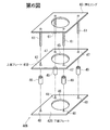
第1図は実施の形態に係るエアバッグ装置の縦断面図、第2図(a)はこのエアバッグ装置の制流部材(ガス流路形成部材)の分解斜視図、第2図(b)は該制流部材の組立後の斜視図、第3図はこのエアバッグ装置の分解斜視図である。 FIG. 1 is a longitudinal sectional view of an airbag device according to an embodiment, FIG. 2 (a) is an exploded perspective view of a flow restricting member (gas flow path forming member) of this airbag device, and FIG. 2 (b). FIG. 3 is a perspective view after assembly of the flow restricting member, and FIG. 3 is an exploded perspective view of the airbag device.
このエアバッグ装置1は、内部が第1室10A及び第2室10Bの2室に区画されたエアバッグ10と、該エアバッグ10を膨張させるインフレータ(ガス発生器)30と、該インフレータ30からのガスを該第1室10A及び第2室10Bに対し個別に流入させる制流部材(ガス流路形成部材)40と、該エアバッグ10、インフレータ30及び制流部材40が取り付けられたリテーナ50等を備えている。
The airbag device 1 includes an airbag 10 that is internally partitioned into two chambers, a first chamber 10A and a second chamber 10B, an inflator (gas generator) 30 that inflates the airbag 10, and an
この実施の形態では、該インフレータ30は、独立してガス発生動作可能な第1のガス発生部31及び第2のガス発生部32の2個のガス発生部を有しており、該制流部材40は、この第1のガス発生部31からのガスをエアバッグ10の第1室10Aに流入させ、第2のガス発生部32からのガスを第2室10Bに流入させうるよう構成されている。
In this embodiment, the
エアバッグ10は、第3図に示すように、それぞれ円形の織布よりなるフロントパネル11、リヤパネル12及びインナーパネル13を備えている。このフロントパネル11とリヤパネル12は同一直径のものであり、両者の外周縁部同士が糸等よりなるシーム14によって縫合されることにより、袋状のエアバッグ外殻が構成されている。この縫合部は、フロントパネル11及びリヤパネル12の外周に沿って周回した円環状となっている。
As shown in FIG. 3, the airbag 10 includes a
リヤパネル12には、インフレータ用開口15とベントホール16とが設けられている。このインフレータ用開口15はリヤパネル12の中央に配置されている。このインフレータ用開口15の周囲にはボルト挿通孔17が設けられている。
The rear panel 12 is provided with an inflator opening 15 and a
このエアバッグ10の内部に前記インナーパネル13が設けられている。このインナーパネル13はフロントパネル11及びリヤパネル12と略同心状に配置され、その外周縁部(エアバッグ10が膨張した状態にあっては、第1図に示す如くインナーパネル13の先端側の周縁部となる部分)が該フロントパネル11の中央部と周縁部との中間部に対し糸等よりなるシーム18によって縫合されている。この縫合部は、インナーパネル13の外周に沿って周回した円環形である。
The inner panel 13 is provided inside the airbag 10. The inner panel 13 is disposed substantially concentrically with the
このインナーパネル13の中央部(エアバッグ10が膨張した状態にあっては、第1図に示す如くインナーパネル13の後端側となる部分)には、該リヤパネル12のインフレータ用開口15と略同心状に配置されるインフレータ用開口19が設けられている。これらの開口15,19はほぼ同一直径となっている。また、このインナーパネル13の該開口19の周囲には、リヤパネル12のボルト挿通孔17と重なるボルト挿通孔20が設けられている。
The central portion of the inner panel 13 (the portion on the rear end side of the inner panel 13 as shown in FIG. 1 when the airbag 10 is inflated) is substantially the same as the inflator opening 15 of the rear panel 12. An inflator opening 19 arranged concentrically is provided. These
インナーパネル13には、その外周縁に比較的近接してインナーベントホール(通気孔)21が設けられている。 The inner panel 13 is provided with an inner vent hole (vent hole) 21 relatively close to the outer peripheral edge thereof.
このインナーパネル13のインフレータ用開口19の周縁部が押えリング60により制流部材40を介してリヤパネル12のインフレータ用開口15の周縁部と共にリテーナ50のインフレータ取付口51の周縁部に連結される。該押えリング60は、該インフレータ用開口19の周縁部に沿って周回する円環状の部材であり、その裏面(インフレータ用開口19の周縁部と重なる側の面)からは、前記の各ボルト挿通孔17,20に挿通されるスタッドボルト61が突設されている。なお、リテーナ50のインフレータ取付口51の周囲にも、このスタッドボルト61が挿通されるボルト挿通孔52が設けられている。
The peripheral edge portion of the
このインナーパネル13により、エアバッグ10の内部が中央の第1室10Aと、該第1室10Aを取り囲む第2室10Bとに区画される。第1室10Aはインナーパネル13の内側である。 The inner panel 13 divides the interior of the airbag 10 into a central first chamber 10A and a second chamber 10B surrounding the first chamber 10A. The first chamber 10 </ b> A is inside the inner panel 13.
制流部材40は、この実施の形態では、第2図(a),(b)に示すように、互いに所定の間隔をあけて対面配置された上面プレート41と下面プレート42とを有している。この実施の形態では、図示の通り、これらの上面プレート41及び下面プレート42はそれぞれ略正方形平板状となっている。該下面プレート42の1対の側辺からは、それぞれ、上面プレート41側に向って略直角に起立して該上面プレート41の下面に当接するスペーサとしての起立片43,43が立設されている。また、上面プレート41の1対の側辺からは、それぞれ、該起立片43,43の外向き面に重なる脚状片44,44が垂設されている。
In this embodiment, as shown in FIGS. 2 (a) and 2 (b), the
第2図(a)のように各脚状片44を各起立片43の外向き面に重ね合わせつつ上面プレート41を下面プレート42に被せ付けることにより、第2図(b)の如き略箱形の制流部材40が構成される。該上面プレート41と下面プレート42との間のスペースがガス流通空間となる。
As shown in FIG. 2 (a), each leg-
なお、この実施の形態では、各起立片43及び各脚状片44に、それぞれ、この制流部材40の内外を連通するガス流通用の窓孔43a,44aが設けられている。
In this embodiment, each standing
該上面プレート41及び下面プレート42の中央部には、それぞれ、前述のインナーパネル13及びリヤパネル12のインフレータ用開口19,15と同様のインフレータ用開口45,46が設けられている。これらの開口45,46は互いに同心状に配置されている。また、該開口45,46の周囲には、これらの開口45,46がそれぞれインナーパネル13及びリヤパネル12の開口19,15と同心状に配置されたときに前述の各ボルト挿通孔20,17と重なるボルト挿通孔47,48が設けられている。
インフレータ30は、この実施の形態では略円筒形状のものである。このインフレータ30の先端側には、筒軸方向に位置を異ならせて第1のガス発生部31と第2のガス発生部32とが設けられている。該第2のガス発生部32は、第1図における第1のガス発生部31の下段側に配置されている。これらの第1及び第2のガス発生部31,32の側周面には、それぞれガス噴出口31a,32aが設けられている。各ガス発生部31,32は、これらのガス噴出口31a,32aから放射状にガスを噴出する。
The inflator 30 has a substantially cylindrical shape in this embodiment. A first gas generation unit 31 and a second
このインフレータ30の筒軸方向の途中部分(該ガス発生部31,32よりも後端側)の側周面からは、インフレータ固定用のフランジ33が突設されている。該フランジ33には、ボルト挿通孔34(第3図)が設けられている。
A
このインフレータ30は、該先端側がリテーナ50のインフレータ取付口51内に嵌装される。該フランジ33は、リテーナ50の下面側において該インフレータ取付口51の周縁部に重ね合わされる。このフランジ33のボルト挿通孔34が該インフレータ取付口51の周囲のボルト挿通孔52と重なる。
The tip side of the inflator 30 is fitted into the
エアバッグ10をリテーナ50に取り付けるに当っては、制流部材40をインナーパネル13とリヤパネル12との間(即ち、第2室10B内)に配置し、該制流部材40の上面プレート41とインナーパネル13とのインフレータ用開口45,19同士及び該制流部材40の下面プレート42とリヤパネル12とのインフレータ用開口46,15同士をそれぞれ重ね合わせると共に、該リヤパネル12のインフレータ用開口15をリテーナ50のインフレータ取付口51に重ね合わせる。
In attaching the airbag 10 to the retainer 50, the
この際、該インフレータ取付口51内に嵌装されたインフレータ30の先端側はこれらの開口15,46,45,19に挿入され、第1図に示すように、その先頭の第1のガス発生部31が第1室10A内に配置されると共に、該第1のガス発生部31よりも下段の第2のガス発生部32が制流部材40内(即ち、第2室10Bの内部空間と連通する、上面プレート41と下面プレート42との間のスペース)に配置される。従って、このインフレータ30(第1及び第2のガス発生部31,32)がガス噴出作動した場合には、該第1のガス発生部31からのガスは、まず第1室10A内にのみ供給され、第2のガス発生部32からのガスは、該制流部材40を介してまず第2室10Bにのみ供給されるようになる。
At this time, the front end side of the inflator 30 fitted in the
次に、インナーパネル13の内側(第1室10A内)から押えリング60により該インナーパネル13のインフレータ用開口19の周縁部を制流部材40の上面プレート41に押え付けると共に、この制流部材40(下面プレート42)を介してリヤパネル12のインフレータ用開口15の周縁部をリテーナ50のインフレータ取付口51の周縁部に押え付ける。なお、この押えリング60を該インフレータ用開口19の周縁部に重ね合わせるに際し、この押えリング60のスタッドボルト61をボルト挿通孔20,47,48,17,52,34に通し、その先端にナット62を締め込むことにより、エアバッグ10(インナーパネル13、リヤパネル12)、制流部材40及びインフレータ30をリテーナ50に固定する。
Next, the peripheral portion of the
その後、エアバッグ10を折り畳み、このエアバッグ10の折り畳み体を覆うようにモジュールカバー53をリテーナ50に取り付けることにより、第1図のエアバッグ装置1が構成される。このエアバッグ装置1は、自動車のステアリングホイール(第1図ではリム部54のみ図示。)に設置される。
Thereafter, the airbag 10 is folded, and the
なお、このエアバッグ装置1には、車両衝突を検知してインフレータ30を作動させる制御装置(図示略)が設けられている。この制御装置は、自動車の運転席に着座した乗員の体重や体格、着座位置(ステアリングホイールからの距離)等に応じて、該インフレータ30の第1及び第2のガス発生部31,32の出力や作動開始時期をそれぞれ個別に調節する調節機能を有している。図示はしないが、このエアバッグ装置1が設置される自動車には、運転席に着座した乗員の体重や体格、着座位置(ステアリングホイールからの距離)等を検出する検出手段が設けられる。該制御装置は、この検出手段からの検出値に基づいて該第1及び第2のガス発生部31,32の出力や作動開始時期を調節する。
The airbag device 1 is provided with a control device (not shown) that activates the inflator 30 by detecting a vehicle collision. This control device outputs the outputs of the first and
このように構成されたエアバッグ装置1においては、車両衝突時等には、インフレータ30(第1のガス発生部31及び第2のガス発生部32)が作動してエアバッグ10内(第1室10A内及び第2室10B内)にガスが噴出する。エアバッグ10は、このガスにより膨張してモジュールカバー53を押し開き、車両室内に展開して運転席乗員を保護する。
In the airbag apparatus 1 configured as described above, the inflator 30 (the first gas generation unit 31 and the second gas generation unit 32) is activated and the interior of the airbag 10 (the first gas generation unit) in the event of a vehicle collision or the like. Gas is ejected into the chamber 10A and the second chamber 10B). The airbag 10 is inflated by this gas to push open the
このエアバッグ装置1にあっては、インフレータ30(第1のガス発生部31及び第2のガス発生部32)がガス噴出作動した場合、実質的に、該第1のガス発生部31からのガスはまずエアバッグ10の第1室10A内にのみ供給されて該第1室の膨張に寄与し、第2のガス発生部32からのガスはまず第2室10B内にのみ供給されて該第2室10Bの膨張に寄与する。従って、これらの第1及び第2のガス発生部31,32の出力や作動開始時期をそれぞれ個別に制御することにより、第1室10Aと第2室10Bとの膨張の順番(膨張開始時期や膨張完了時期)及び膨張時の内圧をそれぞれ個別に制御することができる。
In the airbag device 1, when the inflator 30 (the first gas generation unit 31 and the second gas generation unit 32) performs the gas ejection operation, the air bag device 1 is substantially free from the first gas generation unit 31. The gas is first supplied only into the first chamber 10A of the airbag 10 and contributes to the expansion of the first chamber, and the gas from the
例えば、乗員とステアリングホイール54との間隔が比較的小さい場合や、乗員の体重又は体格が比較的小さい場合などには、第1のガス発生部3の出力を低目に設定する。これにより、第1室10Aの内圧の上昇や乗員側への膨み出しが抑制され、該乗員を比較的ソフトに受け止めることができるようになる。このようにした場合でも、第2室10Bには第2のガス発生部32から十分にガスを供給することができるので、エアバッグ10全体を十分広範囲に膨張させることが可能である。
For example, when the distance between the occupant and the
また、乗員とステアリングホイール54との間隔が非常に大きい場合などには、第1のガス発生部31の出力を高目に設定すると共に、第2のガス発生部32の出力を低目に設定する。このようにした場合には、エアバッグ10の側方への膨張が抑制され、エアバッグ10全体が乗員に向って大きく膨み出すようになる。これにより、該乗員を比較的早期に且つしっかりと受け止めることが可能となる。
Further, when the distance between the occupant and the
なお、この実施の形態では、膨張したエアバッグ10に乗員がぶつかってきた場合、第1室10A及び第2室10Bの内部のガスはインナーベントホール21あるいはベントホール16を通って流出し、衝撃が吸収される。
In this embodiment, when an occupant hits the inflated airbag 10, the gas inside the first chamber 10A and the second chamber 10B flows out through the
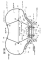
第4図は別の実施の形態に係るエアバッグ装置1Aの縦断面図である。 FIG. 4 is a longitudinal sectional view of an airbag apparatus 1A according to another embodiment.
この実施の形態では、エアバッグ装置1Aは、第1の小エアバッグ70Aと第2の小エアバッグ70Bとからなるエアバッグ70を備えている。第4図の通り、該第1の小エアバッグ70Aは略球形の膨張形状を有したものとなっている。第2の小エアバッグ70Bは、該第1の小エアバッグ70Aの背後側(第1の小エアバッグ70Aの乗員対向面と反対側)に配置されており、該第1の小エアバッグ70Aの後端面(該背後側の面)から側周面に沿って該第1の小エアバッグ70Aよりも側方(放射方向)へ大きく広がった形状に膨張するよう構成されている。
In this embodiment, the airbag apparatus 1A includes an airbag 70 including a first
この実施の形態では、該第1の小エアバッグ70Aの側周面と、該第2の小エアバッグ70Bの前面(乗員側の面)の中央部と周縁部との中間領域とが縫合により一体化されている。符号71はこの縫合のシームを示している。
In this embodiment, the side peripheral surface of the first
また、これらの第1の小エアバッグ70Aと第2の小エアバッグ70Bとの縫合面には、それぞれ、互いに重なる位置にインナーベントホール72a,72bが設けられており、これらのインナーベントホール72a,72bを介して該第1の小エアバッグ70Aと第2の小エアバッグ70Bとが連通している。なお、前記シーム71の一部は、これらのインナーベントホール72a,72bの周囲を周回するように延設されており、このシーム71により、両者の周縁部同士が結合されている。
符号73,74は、それぞれ、各小エアバッグ70A,70B内のガスを外部に流出させるベントホールを示している。
該第1の小エアバッグ70Aの後端面の中央部並びに第2の小エアバッグ70Bの前面の中央部には、それぞれ、インフレータ用開口(符号略)が設けられている。また、該第2の小エアバッグ70Bの後端面の中央部にも、これと同様のインフレータ用開口(符号略)が設けられている。これらのインフレータ用開口は、前述の第1〜3図の実施の形態におけるインナーパネル13及びリヤパネル11の各インフレータ用開口19,15と同様のものであり、互いに同心状に配置しうるようになっている。
An inflator opening (not shown) is provided at the center of the rear end surface of the first
なお、各インフレータ用開口の周囲には、押えリング60のスタッドボルト61を挿通するためのボルト挿通孔(符号略)が設けられている。
A bolt insertion hole (reference numeral omitted) for inserting the
このエアバッグ70を除くエアバッグ装置1Aのその他の構成は前述の第1〜3図のエアバッグ装置1と同様となっており、第4図において第1〜3図と同一符号は同一部分を示している。 Other configurations of the airbag apparatus 1A excluding the airbag 70 are the same as those of the airbag apparatus 1 shown in FIGS. 1 to 3. In FIG. 4, the same reference numerals as those in FIGS. Show.
このエアバッグ70をリテーナ50に取り付けるに当っては、制流部材40を第2の小エアバッグ70B内に配置し、該制流部材40の上面プレート41と、第1の小エアバッグ70Aの後端面中央部及び第2の小エアバッグ70Bの前面中央部との各インフレータ用開口同士、及び該制流部材40の下面プレート42と小エアバッグ70Bの後端面中央部との各インフレータ用開口同士を重ね合わせると共に、該小エアバッグ70Bの後端面中央部のインフレータ用開口をリテーナ50のインフレータ取付口(符号略)に重ね合わせる。
In attaching the airbag 70 to the retainer 50, the
この際、該インフレータ取付口内に嵌装されたインフレータ30の先端側はこれらのインフレータ用開口に挿入され、第4図に示すように、その先頭の第1のガス発生部31が第1の小エアバッグ70A内に配置されると共に、該第1のガス発生部31よりも下段の第2のガス発生部32が制流部材40内(第2の小エアバッグ70Bの内部空間と連通する、上面プレート41と下面プレート42との間のスペース)に配置される。従って、このインフレータ30(第1及び第2のガス発生部31,32)がガス噴出作動した場合には、該第1のガス発生部31からのガスは、まず第1の小エアバッグ70A内にのみ供給され、第2のガス発生部32からのガスは、該制流部材40を介してまず第2の小エアバッグ70Bにのみ供給されるようになる。
At this time, the front end side of the inflator 30 fitted in the inflator attachment port is inserted into these inflator openings, and as shown in FIG. The second
次に、第1の小エアバッグ70A内から押えリング60により、該第1の小エアバッグ70Aの後端面中央部及び第2のエアバッグ70Bの前面中央部の各インフレータ用開口周縁部を制流部材40の上面プレート41に押え付けると共に、この制流部材40(下面プレート42)を介して第2の小エアバッグ70Bの後端面中央部のインフレータ用開口周縁部をリテーナ50のインフレータ取付口の周縁部に押え付ける。そして、この押えリング60のスタッドボルト61を各ボルト挿通孔に通し、その先端にナット62を締め込むことにより、エアバッグ70(第2の小エアバッグ70Aの後端面中央部、第2の小エアバッグ70Bの前面中央部及び後面中央部)並びにインフレータ30をリテーナ50に固定する。
Next, by the
これ以降のエアバッグ装置1Aの構成手順は前述の第1〜3図のエアバッグ装置1と同様である。 The subsequent configuration procedure of the airbag apparatus 1A is the same as that of the airbag apparatus 1 shown in FIGS.
このエアバッグ装置1Aにあっても、インフレータ30(第1のガス発生部31及び第2のガス発生部32)がガス噴出作動した場合、実質的に該第1のガス発生部31からのガスはまず第1の小エアバッグ70A内にのみ供給されて該第1の小エアバッグ70Aの膨張に寄与し、第2のガス発生部32からのガスは、まず第2の小エアバッグ70B内にのみ供給されて該第2の小エアバッグ70Bの膨張に寄与する。従って、これらの第1及び第2のガス発生部31,32の出力や作動開始時期をそれぞれ個別に制御することにより、第1の小エアバッグ70Aと第2の小エアバッグ70Bとの膨張の順番(膨張開始時期や膨張完了時期)及び膨張時の内圧をそれぞれ個別に制御することができる。
Even in the airbag apparatus 1A, when the inflator 30 (the first gas generation unit 31 and the second gas generation unit 32) performs the gas ejection operation, the gas from the first gas generation unit 31 is substantially reduced. First, the gas is supplied only into the first
上記の各実施の形態では、制流部材40の下面プレート42の1対の側辺からそれぞれ立設された起立片43,43と、上面プレート41の1対の側辺から垂設され、該起立片43,43の外向き面に重なっている脚状片44,44とにそれぞれガス流通用の窓孔43a,44aを設けることにより、これらの起立片43及び脚状片44が設けられた側面からも側方へ向ってガスが流出するよう構成されているが、これらの窓孔43a,44aは省略されてもよい。第5図はこのように構成された制流部材40Aの斜視図である。
In each of the above-described embodiments, the
この第5図の制流部材40Aにおいては、各起立片43及び脚状片44にガス流通用の窓孔が設けられていないので、インフレータから該制流部材40A内に噴出したガスは、該制流部材40Aの四方の側面のうち、起立片43及び脚状片44が設けられていない側の側面から流出するようになる。このように構成された制流部材40Aにあっては、インフレータからのガスを所期の方向へ向って案内することが可能である。
In the flow restricting member 40A of FIG. 5, since the gas passage window holes are not provided in the standing
上記の各実施の形態では、下面プレート42の1対の側辺から上面プレート41に向って起立した起立片43,43をスペーサとして該下面プレート42と上面プレート41との間に介在させてガス流通スペースを形成しているが、該上面プレート及び下面プレートとは別体に設けられたスペーサ部材を両者の間に介在させてガス流通スペースを形成してもよい。第6図はこのように構成された制流部材40Bの分解斜視図である。
In each of the above-described embodiments, the standing
この第6図の制流部材40Bにおいては、下面プレート42Bの側辺からスペーサとしての起立片43が立設されておらず、該下面プレート42Bと上面プレート42Bとの間には、これらとは別体に構成された筒状スペーサ49が介在されている。この筒状スペーサ49は、該上面プレート41B及び下面プレート42Bを上下方向に貫通した押えリング60の各スタッドボルト61に被着されている。
In the
このように上面プレート41B及び下面プレート42Bとは別体の筒状スペーサ49を両者の間に介在させてガス流通スペースを形成するよう構成した場合には、該筒状スペーサ49の軸心線方向の長さを変更することにより、ガス流通スペースの大きさを容易に変更することが可能である。
In this way, in the case where the gas distribution space is formed by interposing the
第7図はさらに別の実施の形態に係るエアバッグ装置の縦断面図であり、第8図はこのエアバッグ装置の分解斜視図である。 FIG. 7 is a longitudinal sectional view of an airbag apparatus according to still another embodiment, and FIG. 8 is an exploded perspective view of the airbag apparatus.
この実施の形態に係るエアバッグ装置1Bも、内部が第1室80A及び第2室80Bの2室に区画されたエアバッグ80と、該エアバッグ80を膨張させるインフレータ(ガス発生器)30と、該インフレータ30からのガスを該第1室80A及び第2室80Bに対し個別に流入させる制流部材(ガス流路形成部材)40と、該エアバッグ80、インフレータ30及び制流部材40が取り付けられたリテーナ50等を備えている。
The airbag apparatus 1B according to this embodiment also includes an airbag 80 whose interior is divided into two chambers, a first chamber 80A and a second chamber 80B, and an inflator (gas generator) 30 that inflates the airbag 80. A flow restricting member (gas flow path forming member) 40 for individually flowing the gas from the inflator 30 into the first chamber 80A and the second chamber 80B, and the airbag 80, the
前述の第1〜3図のエアバッグ装置1では、エアバッグ10の内部は、フロントパネル11側からリヤパネル12側まで連続した一枚物のインナーパネル13により、中央の第1室10Aと該第1室10Aを取り囲む第2室10Bとに区画されているが、このエアバッグ装置1Bにおいては、エアバッグ80の内部は、フロントパネル11側の第1インナーパネル13Aとリヤパネル12側の第2インナーパネル13Bとにより、中央の第1室80Aと該第1室80Aを取り囲む第2室80Bとに区画されている。
In the airbag apparatus 1 shown in FIGS. 1 to 3, the interior of the airbag 10 is separated from the central first chamber 10A by the single inner panel 13 extending from the
即ち、第7図に示すように、この実施の形態では、エアバッグ80の内部に前記第1インナーパネル13A及び第2インナーパネル13Bが設けられている。この第1及び第2インナーパネル13A,13Bは、それぞれフロントパネル11及びリヤパネル12と略同心状に配置され、その外周縁部同士が糸等よりなるシーム18Bによって縫合されている。フロントパネル11側の第1インナーパネル13Aの内周縁部(エアバッグ80が膨張した状態にあっては、インナーパネル13Aの先端側の周縁部)が該フロントパネル11の中央部と周縁部との中間部に対し糸等よりなるシーム18Aによって縫合されている。
That is, as shown in FIG. 7, in this embodiment, the first inner panel 13A and the second inner panel 13B are provided inside the airbag 80. The first and second inner panels 13A and 13B are arranged substantially concentrically with the
第8図の通り、リヤパネル12側の第2インナーパネル13Bの中央部(エアバッグ80が膨張した状態にあっては、第2インナーパネル13Bの後端側となる部分)には、該リヤパネル12のインフレータ用開口15と略同心状に配置されるインフレータ用開口19が設けられている。これらの開口15,19はほぼ同一直径となっている。また、このインナーパネル13Bの該開口19の周囲には、リヤパネル12のボルト挿通孔17と重なるボルト挿通孔20が設けられている。
As shown in FIG. 8, the rear panel 12 is disposed at the center of the second inner panel 13B on the rear panel 12 side (the rear end side of the second inner panel 13B when the airbag 80 is inflated). An
第2インナーパネル13Bにはインナーベントホール21が設けられている。なお、該インナーベントホール21は、第1インナーパネル13Aに設けられてもよい。
An
この第2インナーパネル13Bのインフレータ用開口19の周縁部が押えリング60により制流部材40を介してリヤパネル12のインフレータ用開口15の周縁部と共にリテーナ50のインフレータ取付口51の周縁部に連結される。これにより、第2インナーパネル13Bのインフレータ用開口19の周縁部は制流部材40を介してリヤパネル12のインフレータ用開口15の周縁部に連なり、第1及び第2インナーパネル13A,13Bの外周縁部同士が連なり、第1インナーパネル13Aの内周縁部はフロントパネル11に連なったものとなる。
The peripheral portion of the
この第1及び第2インナーパネル13A,13Bにより、エアバッグ80の内部が中央の第1室80Aと、該第1室80Aを取り囲む第2室80Bとに区画される。第1室80Aはインナーパネル13A,13Bの内側である。 By the first and second inner panels 13A and 13B, the interior of the airbag 80 is partitioned into a central first chamber 80A and a second chamber 80B surrounding the first chamber 80A. The first chamber 80A is inside the inner panels 13A and 13B.
このエアバッグ装置1Bにおいても、該インフレータ取付口51内に嵌装されたインフレータ30の先端側はこれらのインフレータ用開口15,19に挿入され、第7図に示すように、その先頭の第1のガス発生部31が第1室80A内に配置されると共に、該第1のガス発生部31よりも下段の第2のガス発生部32が制流部材40内(第2室80Bの内部空間と連通する、上面プレート41と下面プレート42との間のスペース)に配置される。従って、このインフレータ30(第1及び第2のガス発生部31,32)がガス噴出作動した場合には、該第1のガス発生部31からのガスは、まず第1室80A内にのみ供給され、第2のガス発生部32からのガスは、該制流部材40を介してまず第2室80Bにのみ供給されるようになる。
Also in the airbag apparatus 1B, the tip side of the inflator 30 fitted in the
このエアバッグ装置1Bのその他の構成は前述の第1〜3図のエアバッグ装置1と同様となっており、第7,8図において第1〜3図と同一符号は同一部分を示している。 The other structure of this airbag apparatus 1B is the same as that of the airbag apparatus 1 of the above-mentioned FIGS. 1-3, and the same code | symbol as FIGS. 1-3 is shown the same part in FIGS. .
このエアバッグ装置1Bにあっても、インフレータ30(第1のガス発生部31及び第2のガス発生部32)がガス噴出作動した場合、実質的に該第1のガス発生部31からのガスはまず第1室80A内にのみ供給されて該第1室80Aの膨張に寄与し、第2のガス発生部32からのガスは、まず第2室80B内にのみ供給されて該第2室80Bの膨張に寄与する。従って、これらの第1及び第2のガス発生部31,32の出力や作動開始時期をそれぞれ個別に制御することにより、第1室80Aと第2室80Bとの膨張の順番(膨張開始時期や膨張完了時期)及び膨張時の内圧をそれぞれ個別に制御することができる。
Even in the airbag apparatus 1B, when the inflator 30 (the first gas generation unit 31 and the second gas generation unit 32) performs the gas ejection operation, the gas from the first gas generation unit 31 is substantially reduced. Is first supplied only into the first chamber 80A and contributes to the expansion of the first chamber 80A, and the gas from the
このエアバッグ装置1Bにあっては、インナーパネルを、フロントパネル11側の第1インナーパネル13Aとリヤパネル12側の第2インナーパネル13Bとの連結体で構成しているので、第1インナーパネル13A又は第2インナーパネル13Bの大きさを調節することにより、エアバッグ80の膨張時の厚みや形状を調節する設計を容易に行うことができる。
In the airbag device 1B, the inner panel is constituted by a connecting body of the first inner panel 13A on the
この実施の形態では第2インナーパネル13Bにインナーベントホール21を設けているが、第1インナーパネル13Aにインナーベントホール21を設けてもよい。また、第9図のエアバッグ装置1B’におけるエアバッグ80’のように、第1インナーパネル13A及び第2インナーパネル13Bの双方にインナーベントホール21を設けてもよい。なお、このエアバッグ装置1B’のその他の構成は第7,8図のエアバッグ装置1Bと同様となっている。
In this embodiment, the
上記の各実施の形態は本発明の一例を示すものであり、本発明は上記の各実施の形態に限定されるものではない。 Each of the above embodiments shows an example of the present invention, and the present invention is not limited to each of the above embodiments.
例えば、エアバッグ内に設けられる室の個数は3個以上であってもよい。また、エアバッグ内を区画する部材はパネル状のものに限られず、例えばテザー状のものであってもよい。 For example, the number of chambers provided in the airbag may be three or more. Moreover, the member which divides the inside of an airbag is not restricted to a panel-shaped thing, For example, a tether-shaped thing may be sufficient.
本発明においては、3個以上の小エアバッグによりエアバッグを構成してもよい。 In the present invention, the airbag may be constituted by three or more small airbags.
1,1A,1B,1B’ エアバッグ装置
10 エアバッグ
11 フロントパネル
12 リヤパネル
13 インナーパネル
13A 第1インナーパネル
13B 第2インナーパネル
15,19,45,46 インフレータ用開口
30 インフレータ
31 第1のガス発生部
32 第2のガス発生部
40,40A,40B 制流部材(ガス流路形成部材)
41,41B 上面プレート
42,42B 下面プレート
43 脚状片
44 起立片
49 筒状スペーサ
50 リテーナ
51 インフレータ取付口
60 押えリング
61 スタッドボルト
70 エアバッグ
70A 第1の小エアバッグ
70B 第2の小エアバッグ
80,80’ エアバッグ
80A 第1室
80B 第2室
1, 1A, 1B, 1B 'Airbag device 10
41,
Claims (6)
少なくとも一部の室へのガス発生手段からのガス供給が他の室へのガス発生手段からのガス供給と独立して制御可能であることを特徴とするエアバッグ装置。 In an airbag apparatus having an airbag having a plurality of chambers and gas generating means for inflating the airbag,
An air bag apparatus characterized in that gas supply from gas generating means to at least some chambers can be controlled independently of gas supply from gas generating means to other chambers.
各ガス発生部からのガスがそれぞれ別の室へ供給されることを特徴とするエアバッグ装置。 In claim 1, the gas generating means comprises an inflator having a plurality of gas generating portions capable of independently generating gas.
The airbag apparatus characterized by the gas from each gas generation part being supplied to a separate chamber, respectively.
各インフレータからのガスがそれぞれ別の室へ供給されることを特徴とするエアバッグ装置。 In Claim 1, the gas generating means comprises a plurality of independently inflatable gas generating inflators,
An air bag apparatus in which gas from each inflator is supplied to a separate chamber.
少なくとも一部のエアバッグへのガス発生手段からのガス供給が他のエアバッグへのガス発生手段からのガス供給と独立して制御可能であることを特徴とするエアバッグ装置。 An airbag device having a plurality of airbags and gas generating means for inflating each airbag,
An air bag apparatus characterized in that gas supply from gas generating means to at least some airbags can be controlled independently of gas supply from gas generating means to other airbags.
各ガス発生部からのガスがそれぞれ別のエアバッグへ供給されることを特徴とするエアバッグ装置。 In Claim 4, the gas generating means comprises an inflator having a plurality of gas generating units capable of independently generating gas,
An airbag device, wherein gas from each gas generation unit is supplied to a separate airbag.
各インフレータからのガスがそれぞれ別のエアバッグへ供給されることを特徴とするエアバッグ装置。 In Claim 4, the gas generating means comprises a plurality of independently inflatable gas generating inflators,
An airbag device characterized in that gas from each inflator is supplied to a separate airbag.
Priority Applications (4)
| Application Number | Priority Date | Filing Date | Title |
|---|---|---|---|
| JP2004064555A JP2005247272A (en) | 2004-02-06 | 2004-03-08 | Air bag apparatus |
| EP05000395A EP1564081A3 (en) | 2004-02-06 | 2005-01-11 | Airbag apparatus |
| CNA2005100070202A CN1651285A (en) | 2004-02-06 | 2005-01-31 | Airbag apparatus |
| US11/045,347 US20050173897A1 (en) | 2004-02-06 | 2005-01-31 | Airbag apparatus |
Applications Claiming Priority (2)
| Application Number | Priority Date | Filing Date | Title |
|---|---|---|---|
| JP2004030996 | 2004-02-06 | ||
| JP2004064555A JP2005247272A (en) | 2004-02-06 | 2004-03-08 | Air bag apparatus |
Publications (1)
| Publication Number | Publication Date |
|---|---|
| JP2005247272A true JP2005247272A (en) | 2005-09-15 |
Family
ID=34703357
Family Applications (1)
| Application Number | Title | Priority Date | Filing Date |
|---|---|---|---|
| JP2004064555A Withdrawn JP2005247272A (en) | 2004-02-06 | 2004-03-08 | Air bag apparatus |
Country Status (4)
| Country | Link |
|---|---|
| US (1) | US20050173897A1 (en) |
| EP (1) | EP1564081A3 (en) |
| JP (1) | JP2005247272A (en) |
| CN (1) | CN1651285A (en) |
Cited By (9)
| Publication number | Priority date | Publication date | Assignee | Title |
|---|---|---|---|---|
| JP2007008444A (en) * | 2005-01-11 | 2007-01-18 | Takata Corp | Airbag and airbag device |
| JP2007099122A (en) * | 2005-10-05 | 2007-04-19 | Takata Corp | Airbag and airbag device |
| JP2007210519A (en) * | 2006-02-10 | 2007-08-23 | Autoliv Development Ab | Air bag apparatus |
| WO2007122997A1 (en) * | 2006-04-20 | 2007-11-01 | Takata Corporation | Airbag and airbag device |
| JP2011213301A (en) * | 2010-04-01 | 2011-10-27 | Nippon Plast Co Ltd | Airbag device |
| JP2017159777A (en) * | 2016-03-09 | 2017-09-14 | 株式会社Subaru | Driver seat air bag device |
| US9925948B2 (en) | 2015-09-29 | 2018-03-27 | Toyoda Gosei Co., Ltd. | Airbag |
| GB2558080A (en) * | 2016-12-09 | 2018-07-04 | Ford Global Tech Llc | Airbag with side chambers |
| US10155496B2 (en) | 2016-12-09 | 2018-12-18 | Ford Global Technologies, Llc | Airbag with side chambers |
Families Citing this family (10)
| Publication number | Priority date | Publication date | Assignee | Title |
|---|---|---|---|---|
| JP4626300B2 (en) * | 2004-12-28 | 2011-02-02 | タカタ株式会社 | Airbag device for driver's seat |
| US8333406B2 (en) * | 2010-10-06 | 2012-12-18 | Toyota Motor Engineering & Manufacturing North America, Inc. | Method and system for multi-stage inflation of a curtain airbag for ejection mitigation |
| CN102975682B (en) * | 2012-11-05 | 2015-08-26 | 浙江吉利汽车研究院有限公司杭州分公司 | Safety air bag |
| KR102216133B1 (en) * | 2014-08-14 | 2021-02-16 | 현대모비스 주식회사 | Passenger Airbag of Vehicle |
| CN106143392A (en) * | 2016-07-13 | 2016-11-23 | 芜湖金鹏汽车部件有限公司 | A kind of Automobile Airbag |
| CN106004757A (en) * | 2016-07-13 | 2016-10-12 | 芜湖金鹏汽车部件有限公司 | Safety airbag control system |
| DE202018101242U1 (en) * | 2018-03-06 | 2019-06-07 | Trw Automotive Safety Systems Gmbh | Airbag and gas bag module for a motor vehicle with such a gas bag |
| JP7093014B2 (en) * | 2019-03-28 | 2022-06-29 | 豊田合成株式会社 | Airbag for steering wheel |
| US11198411B2 (en) * | 2019-04-18 | 2021-12-14 | Autoliv Asp. Inc. | Energy-absorbing airbag diffusers and related airbag assemblies |
| FR3095622B1 (en) * | 2019-04-30 | 2021-04-02 | Psa Automobiles Sa | Driver's airbag with two pockets |
Family Cites Families (21)
| Publication number | Priority date | Publication date | Assignee | Title |
|---|---|---|---|---|
| DE1280072B (en) * | 1966-08-03 | 1968-10-10 | Daimler Benz Ag | Inflatable container for protecting the occupants of vehicles, in particular motor vehicles, against impact injuries in the event of collisions |
| US3752501A (en) * | 1971-10-20 | 1973-08-14 | Ford Motor Co | Steering wheel inflatable cushion device |
| JPH0274440A (en) | 1988-09-07 | 1990-03-14 | Nippon Plast Co Ltd | Passenger protective device of automobile and the like |
| JPH0332956A (en) * | 1989-06-30 | 1991-02-13 | Mazda Motor Corp | Air bag device for automobile |
| JP3039068B2 (en) * | 1991-12-04 | 2000-05-08 | タカタ株式会社 | Air bag |
| JP3352203B2 (en) * | 1993-12-08 | 2002-12-03 | タカタ株式会社 | Airbag device |
| DE19538657A1 (en) * | 1995-10-17 | 1997-04-24 | Trw Repa Gmbh | Airbag side impact protection device |
| US6095561A (en) * | 1997-03-07 | 2000-08-01 | Automotive Systems Laboratory, Inc. | Multi-chamber inflator |
| US6851705B2 (en) * | 1998-06-19 | 2005-02-08 | Autoliv Asp, Inc. | Dual output inflator with independent gas storage vessels |
| JP4129758B2 (en) * | 1998-08-10 | 2008-08-06 | 俊毅 内田 | Airbag device |
| DE29822159U1 (en) * | 1998-12-11 | 1999-05-12 | Trw Repa Gmbh | Airbag side impact protection device |
| US6254121B1 (en) | 1998-12-14 | 2001-07-03 | Breed Automotive Technology, Inc. | Chambered driver side air bag and module attachment method |
| DE19904740A1 (en) * | 1999-02-05 | 2000-08-10 | Volkswagen Ag | Safety device with an airbag arrangement comprising a plurality of airbags for a motor vehicle |
| WO2001012475A1 (en) * | 1999-08-16 | 2001-02-22 | Autoliv Development Ab | Motor vehicle air bag system with a cable-type gas generator |
| DE20102115U1 (en) * | 2001-02-07 | 2001-06-28 | Trw Automotive Safety Sys Gmbh | Airbag module |
| US6863301B2 (en) * | 2001-02-23 | 2005-03-08 | Key Safety Systems, Inc. | Driver side air bag module with annular air bag and centrally disposed control module |
| US6616177B2 (en) * | 2001-06-11 | 2003-09-09 | General Motors Corporation | Dual depth airbag |
| JP2003034208A (en) * | 2001-07-24 | 2003-02-04 | Takata Corp | Airbag |
| JP2003170796A (en) * | 2001-12-06 | 2003-06-17 | Takata Corp | Airbag |
| JP3915544B2 (en) * | 2002-02-25 | 2007-05-16 | タカタ株式会社 | Airbag device |
| US7063350B2 (en) * | 2003-09-23 | 2006-06-20 | Autoliv Asp, Inc. | Dual chamber side airbag apparatus and method |
-
2004
- 2004-03-08 JP JP2004064555A patent/JP2005247272A/en not_active Withdrawn
-
2005
- 2005-01-11 EP EP05000395A patent/EP1564081A3/en not_active Withdrawn
- 2005-01-31 CN CNA2005100070202A patent/CN1651285A/en active Pending
- 2005-01-31 US US11/045,347 patent/US20050173897A1/en not_active Abandoned
Cited By (9)
| Publication number | Priority date | Publication date | Assignee | Title |
|---|---|---|---|---|
| JP2007008444A (en) * | 2005-01-11 | 2007-01-18 | Takata Corp | Airbag and airbag device |
| JP2007099122A (en) * | 2005-10-05 | 2007-04-19 | Takata Corp | Airbag and airbag device |
| JP2007210519A (en) * | 2006-02-10 | 2007-08-23 | Autoliv Development Ab | Air bag apparatus |
| WO2007122997A1 (en) * | 2006-04-20 | 2007-11-01 | Takata Corporation | Airbag and airbag device |
| JP2011213301A (en) * | 2010-04-01 | 2011-10-27 | Nippon Plast Co Ltd | Airbag device |
| US9925948B2 (en) | 2015-09-29 | 2018-03-27 | Toyoda Gosei Co., Ltd. | Airbag |
| JP2017159777A (en) * | 2016-03-09 | 2017-09-14 | 株式会社Subaru | Driver seat air bag device |
| GB2558080A (en) * | 2016-12-09 | 2018-07-04 | Ford Global Tech Llc | Airbag with side chambers |
| US10155496B2 (en) | 2016-12-09 | 2018-12-18 | Ford Global Technologies, Llc | Airbag with side chambers |
Also Published As
| Publication number | Publication date |
|---|---|
| EP1564081A2 (en) | 2005-08-17 |
| US20050173897A1 (en) | 2005-08-11 |
| EP1564081A3 (en) | 2006-05-31 |
| CN1651285A (en) | 2005-08-10 |
Similar Documents
| Publication | Publication Date | Title |
|---|---|---|
| EP1442944B1 (en) | Airbag and airbag apparatus | |
| JP4604765B2 (en) | Airbag device | |
| US20050173897A1 (en) | Airbag apparatus | |
| JP5186832B2 (en) | Air bag and air bag device | |
| JP2006248511A (en) | Airbag and airbag device | |
| KR20010101935A (en) | Side airbag system | |
| JP2003170796A (en) | Airbag | |
| JP2006306149A (en) | Airbag, and airbag device | |
| JP2007055577A (en) | Airbag and airbag device | |
| JP2007008444A (en) | Airbag and airbag device | |
| JP2007099122A (en) | Airbag and airbag device | |
| JP2008189132A (en) | Side airbag device | |
| JP4363179B2 (en) | Air bag and air bag device | |
| JP4135514B2 (en) | Airbag device | |
| JP2007284026A (en) | Airbag and airbag device | |
| JP2008001270A (en) | Side airbag device | |
| JP4135515B2 (en) | Airbag device | |
| JP2004210047A (en) | Airbag apparatus | |
| US7416209B2 (en) | Airbag apparatus | |
| JP4626300B2 (en) | Airbag device for driver's seat | |
| JP4992799B2 (en) | Side airbag device | |
| JP2004148925A (en) | Air bag for driver's seat, and air bag device for driver's seat | |
| JP2016060481A (en) | Side airbag apparatus | |
| JP2009023493A (en) | Airbag device | |
| JP4534762B2 (en) | Airbag device for driver's seat |
Legal Events
| Date | Code | Title | Description |
|---|---|---|---|
| A711 | Notification of change in applicant |
Free format text: JAPANESE INTERMEDIATE CODE: A712 Effective date: 20060317 |
|
| A300 | Application deemed to be withdrawn because no request for examination was validly filed |
Free format text: JAPANESE INTERMEDIATE CODE: A300 Effective date: 20070605 |