JP2005244753A - State change management system of household electric devices - Google Patents
State change management system of household electric devices Download PDFInfo
- Publication number
- JP2005244753A JP2005244753A JP2004053761A JP2004053761A JP2005244753A JP 2005244753 A JP2005244753 A JP 2005244753A JP 2004053761 A JP2004053761 A JP 2004053761A JP 2004053761 A JP2004053761 A JP 2004053761A JP 2005244753 A JP2005244753 A JP 2005244753A
- Authority
- JP
- Japan
- Prior art keywords
- home
- home gateway
- state change
- notification
- information server
- Prior art date
- Legal status (The legal status is an assumption and is not a legal conclusion. Google has not performed a legal analysis and makes no representation as to the accuracy of the status listed.)
- Pending
Links
Images


Landscapes
- Telephonic Communication Services (AREA)
- Selective Calling Equipment (AREA)
Abstract
Description
本発明は、無線または有線によって構内ネットワークへ接続可能な家電機器の状態変化を管理する家電機器の状態変化管理システムに関する。 The present invention relates to a home appliance state change management system that manages a change in state of a home appliance that can be connected to a local network wirelessly or by wire.
従来、遠隔地の住人の安否確認する場合、その住人が所有する家電機器から生活情報をインターネットを通じてアクセスして取得することが考えられているものの、この方法では、家電機器毎に外部からのアクセスを許容する機能を付与する必要があり、家電機器の開発コストが大きいと共に製品が高くなる。また、家電機器から通知される情報には多くの生活情報が含まれており、1回の通信で取り扱うことのできる情報量が限られている家電機器にとっては負担が大きい。 Conventionally, when confirming the safety of a resident in a remote location, it has been considered to obtain life information from home appliances owned by the resident through the Internet. It is necessary to provide a function that allows the product, and the development cost of home appliances is high and the product is expensive. In addition, a lot of life information is included in the information notified from the home appliance, and the burden is great for the home appliance having a limited amount of information that can be handled by one communication.
そこで、家電機器の負荷を減らすため、特許文献1のように家電機器に状態変化が発生したときに、インターネット上の情報サーバに通知情報を直接送信することにより、家電機器の負荷を軽減し、情報サーバを介して生活情報を得るシステムが提案されている。
しかしながら、上述したようなシステムでは、全国の家庭に設置される家電機器のように情報サーバが扱わなければならない台数が膨大であり、さらに状態変化が頻繁に発生するものをサービス対象とした場合、情報通知総数が膨大な量となり、情報サーバの負荷が大きくなってしまう。このため。このような条件を満たす情報サーバを設置しようとすると、極めて高性能のものが必要となってしまう。 However, in the system as described above, when the number of information servers that the information server has to handle, such as household electrical appliances installed in homes nationwide, is further targeted for services that frequently change state, The total number of information notifications becomes enormous, and the load on the information server increases. For this reason. If an information server that satisfies such conditions is installed, an extremely high performance server is required.
本発明は上記事情に鑑みてなされたもので、その目的は、ユーザの操作を必要としないで自律的に家電機器の動作を管理可能なシステム構成でありながら、特定の機器に大きな負荷がかかることを防止できる家電機器の状態変化管理システムを提供することにある。 The present invention has been made in view of the above circumstances, and its purpose is a system configuration capable of autonomously managing the operation of home appliances without requiring user operation, but places a heavy load on specific devices. An object of the present invention is to provide a state change management system for household electrical appliances that can prevent this.
本発明の家電機器の状態変化管理システムは、無線または有線によって構内ネットワークへ接続され、状態変化が発生したときは上記構内ネットワーク内へ状態変化の通知を行う家電機器を設け、この家電機器から状態変化の通知を受け取ったときは、通知時間、対象機器など必要な動作履歴データをまとめた履歴保存ファイルに新規の動作履歴データを追加すると共に、所定タイミングで上記履歴保存ファイルを公衆ネットワークを通じて送信するホームゲートウェイを設け、このホームゲートウェイから履歴保存ファイルを受信したときは、家電機器の状態変化の動作履歴データを顧客に対応して管理する情報サーバを設けたものである。 The home appliance state change management system of the present invention is connected to a local network wirelessly or by wire, and when a state change occurs, a home appliance that notifies the state change is provided in the local network, and the home appliance is in a state When a change notification is received, new operation history data is added to a history storage file that summarizes necessary operation history data such as notification time and target device, and the history storage file is transmitted through a public network at a predetermined timing. When a home gateway is provided and a history storage file is received from the home gateway, an information server is provided that manages operation history data of the state change of the home appliance corresponding to the customer.
上記構成において、前記所定タイミングは、一定時間毎であるようにしてもよい(請求項2)。
また、前記所定タイミングは、一定時間毎の所定時刻から前記ホームゲートウェイに割り当てられた固有番号に基づいて算出したランダムな時間だけ待機したタイミングとしてもよい(請求項3)。
The said structure WHEREIN: You may make it the said predetermined timing be every fixed time (Claim 2).
The predetermined timing may be a timing of waiting for a random time calculated based on a unique number assigned to the home gateway from a predetermined time every predetermined time.
また、前記情報サーバにアクセス可能なクライアント端末を設けた上で、前記ホームゲートウェイは、外部から取得要求されたときは、少なくとも最新の動作履歴データを送信し、前記情報サーバは、前記クライアント端末から最新のデータを要求されたときは、前記ホームゲートウェイに取得要求することにより最新の動作履歴データを取得してから、当該動作履歴データを前記クライアント端末に送信し、前記クライアント端末は、前記情報サーバから取得した動作履歴データを表示するようにしてもよい(請求項4)。 In addition, after providing a client terminal that can access the information server, the home gateway transmits at least the latest operation history data when an acquisition request is received from the outside, and the information server receives the information from the client terminal. When the latest data is requested, the latest operation history data is acquired by requesting acquisition from the home gateway, and then the operation history data is transmitted to the client terminal. The operation history data acquired from the above may be displayed (claim 4).
また、前記家電機器は、異常を外部に通知するための異常フラグを有し、異常状態となった場合は上記異常フラグをONすることにより異常フラグの状態変化通知を行い、前記ホームゲートウェイは、異常フラグの状態変化通知を受け取った場合は、異常処理を実行した後、前記家電機器の異常フラグをOFFするようにしてもよい(請求項5)。
また、ホームゲートウェイは、起動したときは、構内ネットワークに接続された家電機器を検出し、検出した家電機器の異常フラグをOFFするようにしてもよい(請求項6)。
Further, the home appliance has an abnormality flag for notifying the outside of an abnormality, and when an abnormal state occurs, the abnormality flag state change notification is performed by turning on the abnormality flag. When the abnormality flag state change notification is received, the abnormality flag of the home appliance may be turned off after executing the abnormality process.
Further, when the home gateway is activated, it may detect a home appliance connected to the local network and turn off the abnormality flag of the detected home appliance.
また、前記ホームゲートウェイは、前記情報サーバからの要求に応じて必要な情報を通知したときは、全ての動作履歴データを消去するようにしてもよい(請求項7)。
また、前記ホームゲートウェイは、動作履歴データを消去する際は、前記履歴保存ファイルへの他のプログラムからのアクセスを禁止した状態で実行すると共に、他のプログラムがアクセスしている場合は、消去する前に動作履歴データを前記情報サーバへ通知するようにしてもよい(請求項8)。
The home gateway may delete all the operation history data when notifying necessary information in response to a request from the information server.
In addition, when erasing the operation history data, the home gateway is executed in a state where access from the other program to the history storage file is prohibited, and when the other program is accessing, the home gateway erases the operation history data. The operation history data may be notified to the information server before (claim 8).
請求項1の発明によれば、ホームゲートウェイから情報サーバに送られるデータは動作履歴データをまとめた一つの履歴保存ファイルであるので、情報サーバは、状態変化が発生する毎に各家電機器から動作履歴データをバラバラなタイミングで受信する場合に比較して、受信或いはその後の処理のための負荷を大幅に軽減することができる。
請求項2の発明によれば、情報サーバはホームゲートウェイから一定時間毎にアクセスされるので、情報サーバへのアクセスが制限され、情報サーバの負荷を一層軽減することができる。
According to the first aspect of the present invention, since the data sent from the home gateway to the information server is a single history storage file in which operation history data is collected, the information server operates from each home appliance every time a state change occurs. Compared to the case where history data is received at different timings, the load for reception or subsequent processing can be greatly reduced.
According to the invention of
ところで、各ホームゲートウェイが一定時間毎の所定時刻に履歴保存ファイルを情報サーバに送信した場合は、情報サーバは、所定時刻のみ待ち受けプログラムを起動すればよいものの、情報サーバへのアクセスが同時に集中して負荷が大きくなる。
そこで、請求項3の発明によれば、ホームゲートウェイは、一定時刻毎の所定時刻から自己に割り当てられた固有番号に基づいて算出したランダムな時間だけ待機してから情報サーバにアクセスするので、情報サーバにアクセスされるタイミングが少しずつずれる。これにより、情報サーバは、各ホームゲートウェイからの履歴保存ファイルを確実に受信することができる。
By the way, when each home gateway sends a history storage file to the information server at a predetermined time every predetermined time, the information server only needs to start a standby program at a predetermined time, but access to the information server is concentrated simultaneously. Increases the load.
Therefore, according to the invention of
請求項4の発明によれば、クライアント端末から情報サーバにアクセスすると、クライアント端末は、情報サーバがホームゲートウェイから取得した最新の動作履歴データを表示するので、ユーザは、家電機器の最新の動作履歴を遠隔地から確認することができる。
請求項5の発明によれば、家電機器が異常となり、異常フラグをONした後に、別の異常が発生した場合であっても、異常処理を実行したホームゲートウェイにより異常フラグはOFFされているので、異常フラグがONとなることにより次の異常をホームゲートウェイに確実に通知することができる。
According to the invention of
According to the invention of
ここで、家電機器の異常フラグがONしている状態でホームゲートウェイが起動した場合、家電機器の異常に対処することができないものの、請求項6の発明によれば、ホームゲートウェイは、起動したときは、構内ネットワークに接続された家電機器の異常フラグをOFFするので、家電機器は、異常を確実に通知することができる。
請求項7の発明によれば、不必要な動作履歴データを消去することによりメモリの負荷を軽減することができる。
Here, when the home gateway is activated while the abnormality flag of the home appliance is ON, the home gateway cannot be dealt with, but according to the invention of
According to the seventh aspect of the present invention, it is possible to reduce the load on the memory by deleting unnecessary operation history data.
ところで、履歴消去中に家電機器の状態通知が行われた場合、その状態通知は情報サーバへ通知されないまま、消去されてしまう可能性があるものの、請求項8の発明によれば、動作履歴データを消去する最中には、履歴保存ファイルへ他のプログラムがアクセスできないようにし、消去が終了した後に動作履歴データを書き込むので、消去されてしまうことを防止できる。また、履歴消去開始時に、他のプログラムがアクセスしている場合には、動作履歴データが保存されている最中である場合が考えられる。このようにアクセス終了時に消去を行ってしまうと、この場合も、動作履歴データが情報サーバへ通知されないまま消去されてしまう可能性があることから、消去する前に動作履歴データを情報サーバへ通知することによって、動作履歴データの抜けを防止することができる。 By the way, when the status notification of the home electric appliance is performed during the history erasure, the status notification may be erased without being notified to the information server. During erasure, the history storage file is prevented from being accessed by other programs, and the operation history data is written after the erasure is completed, so that it can be prevented from being erased. Further, when another program is accessing at the start of history erasure, there may be a case where the operation history data is being saved. If erasure is performed at the end of access in this way, the operation history data may be erased without being notified to the information server in this case, so the operation history data is notified to the information server before erasure. By doing so, it is possible to prevent missing of operation history data.
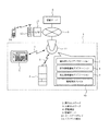
以下、本発明の一実施例を図面に基づいて説明する。例えば図1に示すように、例えば建物1内には構内ネットワークであるサブネットワーク2が構築され、建物1外部には公衆ネットワークであるインターネット3が構築されている。
サブネットワーク2は、例えば冷蔵庫,電子レンジなどの家電機器4が接続されるようになっており、例えば物理層として無線通信プロトコルであるBluetooth(登録商標)を用いた無線ネットワークからなる。このサブネットワーク2は、無線回線を介して接続された家電機器4及びホーム端末5と、インターネット3上の情報サーバ6に接続するための制御等を行うように例えば台所の天井に設置されたホームゲートウェイ11とからなる
ホーム端末5は、ホームサーバとして機能し、ホームゲートウェイ11を通じて各家電機器4と通信を行うと共に、ホームゲートウェイ11およびインターネット3を通じてメーカのWebサーバにアクセスしたりメールの送受信を行うようになっている。
Hereinafter, an embodiment of the present invention will be described with reference to the drawings. For example, as shown in FIG. 1, for example, a
The
家電機器4は、TCP/IPプロトコルを実装したいわゆる「ネットワーク家電」である。これらの家電機器4には、サブネットワークに接続される全ての機器に対して重複のない固有のIPアドレス(プライベートIPアドレス)がホームゲートウェイ11により割り当てられている。また、各家電機器4には、固有の識別情報(家電ID)が設定されており、本実施例では、家電IDとして、IEEE1394のEUI64等のMAC(Media Access Control)アドレスが設定されている。
The
ホームゲートウェイ11は、ホーム端末5と各家電機器4とが通信可能となるようにプロトコル(Ethernet(登録商標)、Bluetooth、ECHONET(電力線を通じたネットワーク))を変換すると共に、インターネット3とサブネットワーク2とを接続するルータとしての機能を有する。この場合、ルータとして機能する場合には、不正なデータの入出力を阻止するファイヤーウォールとしても機能するようになっている。
The
ホームゲートウェイ11は、DHCP(Dynamic Host Configuration Protocol)サーバの機能を備えており、サブネットワーク2に接続される各家電機器4にプライベートなIPアドレスを割り当てる。また、ホームゲートウェイ11は、サブネットワーク2を通じて各家電機器4から収集したデータをインターネット3上の情報サーバ6にアクセスする機能を備えている。このような機能を実現するために、ホームゲートウェイ11には、図1に示す通知待ち受けアプリケーション7、保存情報通知アプリケーション8、現在情報通知アプリケーション9が搭載されていると共に、それらのアプリケーションが参照する履歴保存ファイル10が設けられている。
The
一方、インターネット3上にはゲートウェイ12を介して基地局13が接続されており、携帯電話機のようなクライアント端末14から情報サーバ6にインターネット3を通じてアクセス可能となっている。
インターネット3で用いられるTCP/IPパケットは、ヘッダとペイロードとから構成されている。ヘッダには、宛先の機器のIPアドレス、送信元の機器のIPアドレス、送信先のポート番号等が格納されている。また、ペイロードには、所定データ等が格納される。
On the other hand, a
A TCP / IP packet used in the Internet 3 is composed of a header and a payload. The header stores the IP address of the destination device, the IP address of the source device, the port number of the destination, and the like. The payload stores predetermined data and the like.
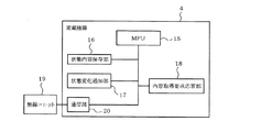
図2は、家電機器4の構成を示す機能ブロック図である。この図2において、家電機器4は、MPU(Micro Processing Unit)15主体としてなり、データが保存される状態内容保存部16、状態変化を外部に通知する状態変化通知部17、外部からの要求に応答する内容取得要求応答部18、無線ユニット19を通じて外部との通信を行う通信部20を備えて構成されている。
FIG. 2 is a functional block diagram showing the configuration of the
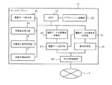
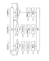
図3は、ホームゲートウェイ11の構成を示す機能ブロック図である。この図3において、ホームゲートウェイ11は、MPU21を主体としてなり、図1に示す各アプリケーション(通知待ち受けアプリケーション7、保存情報通知アプリケーション8、現在情報通知アプリケーション9)が記憶されたアプリケーション記憶部22に加えて、サブネットワーク2を通じて他の機器と通信する家庭内側通信部23、この家庭内側通信部23を通じて家電機器4からの状態変化通知を受信する状態変化通知受信部24、この状態変化通知受信部24が受信した状態変化を保存可能なデータに変換する状態変化加工部25、この状態変化加工部25により加工されたデータからなる履歴保存ファイル10(図1参照)が記憶される履歴データ保存部26、この履歴データ保存部26に記憶された履歴保存ファイル10を出力する履歴データ自動通知制御部27、この履歴データ自動通知制御部27から出力されたデータをWAN側通信部28を通じてインターネット3上の情報サーバ6に送信する履歴データ送信部29、情報サーバ6からの要求を受ける要求受信部30、この要求受信部30が受信した取得要求に応えて履歴データ保存部26に記憶されている動作履歴を履歴データ送信部29に出力する履歴データ取得要求応答部31とから構成されている。
FIG. 3 is a functional block diagram showing the configuration of the
図1に戻って、情報サーバ6は、例えばMPU、メモリ、HDD(Hard Disk Drive)等の補助記憶装置を有する情報処理装置からなる。この情報サーバ6は、例えばホーム端末5からの指示に従って、サブネットワーク2に接続されている機器の制御等のサービスあるいは当該サービスの申し込みサービス等を提供すると共に、サービスの提供のために用いるデータ等を保持するデータベースを備えている。
Returning to FIG. 1, the
また、情報サーバ6は、例えばクライアント端末14で機能しているWebブラウザをフロントエンドとしてサービスの提供を行うHTTPサーバの機能を有している。データベースには、個々のユーザ(顧客)についての情報を保持する顧客データベースを備えている。この顧客データベースには、個々のユーザを識別するための情報(ユーザ名)、当該ユーザについて情報(ユーザ情報)、当該ユーザが所有する全ての家電機器4の家電ID(所有家電の家電ID)、当該家電機器4の種別及び型番を示す情報(種別・型番)、ホームゲートウェイ11までの通信方法を示す情報(アクセス:例えばIPv6かIPv4か等)を対応付ける対応テーブルが格納されている。
Further, the
ユーザ情報としては、例えば当該ユーザの住所、氏名、年齢、職業、電話番号、ネットワーク接続サービスの提供者(プロバイダ)、電子メールアドレス、当該ユーザの好み等を示す情報からなる。
家電IDは、ユーザが家電機器4を購入する際に、当該ユーザの氏名等に対応付けて情報サーバ6に登録する。具体的には、例えばユーザが家電機器4を購入する際に、販売店等から住所、氏名等を記入する用紙を提供し、ユーザが記入した内容を、例えば販売店の店員等がネットワーク経由で情報サーバ6に接続された図示しない端末装置等を介して入力し、入力された情報を当該端末装置が情報サーバ6に供給する。また、ユーザがホーム端末5から直接登録するようにしてもよい。
The user information includes, for example, information indicating the user's address, name, age, occupation, telephone number, network connection service provider (provider), e-mail address, user's preferences, and the like.
The home appliance ID is registered in the
情報サーバ6に供給された情報は、顧客データベースに登録され、ユーザが購入した家電機器4を示す家電ID等の情報が、当該ユーザのユーザ名,ユーザ情報に対応付けて顧客データベース中の対応テーブルに記録される。この顧客のデータベース中では、ユーザ名毎あるいは同一のユーザ名及び住所等のユーザ情報の少なくとも一部が同一であるユーザ毎に、登録された機器の家電ID等を管理する。ユーザ名、住所等の条件が全て同一であるユーザ毎に、当該ユーザが所有する家電機器4についての情報を管理するようにしている。
顧客のデータベースをこのような構成とすることにより、ユーザ名あるいはユーザ情報を検索キーとして当該ユーザが所有する家電機器4の一覧を検索することができるようになっている。
The information supplied to the
By configuring the customer database in this way, it is possible to search a list of
次に上記構成の作用について説明する。
(ホームゲートウェイ11の起動動作)
ホームゲートウェイ11は、電源投入により起動したときは、全てのアプリケーション7〜9を自動起動する。これにより、以後においては、各アプリケーション7〜9が並列動作するようになる。
尚、ホームゲートウェイ11は、負荷を軽減するために、サービスの登録が行われていない場合には、アプリケーションの起動を行わないようになっている。
Next, the operation of the above configuration will be described.
(Startup operation of home gateway 11)
When the
In order to reduce the load, the
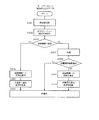
(家電機器4の起動動作)
図4は家電機器4の動作を示すフローチャートで、本発明に関連した部分のみを示している。この図4において、ユーザが家電機器4の電源を投入すると、家電機器4の電源が立ち上がり、ホームゲートウェイ11との接続を実行する(S101)。つまり、家電機器4のエコーネットの設定が初期化され、例えばエコーネットアドレスが決定される。この後、家電機器4は、サブネットワーク2内に起動通知をブロードキャストし、自身が起動したことを他機器に報知する。
(Start-up operation of home appliance 4)
FIG. 4 is a flowchart showing the operation of the
ホームゲートウェイ11にはDHCPサーバの機能が搭載されており、エコーネットにより家電機器4が起動したことを通知されたときは、サブネットワーク2のプライベートIPアドレスを家電機器4に割り振る。これにより、家電機器4は、Bluetoothによりホームゲートウェイ11と接続される。
ここで、ホームゲートウェイ11は、起動した家電機器4の情報をデータベースに登録する。この登録データとしては、家電機器4が通知したMACアドレスと機器名を用い、IPアドレスはホームゲートウェイ11自身が割り振ったものを登録する。
そして、ホームゲートウェイ11と接続された家電機器4は、待機状態に移行して次のイベントが発生するのを監視する(S102)。
The
Here, the
And the
(通知待ち受けアプリケーション7の初期化動作(その1))
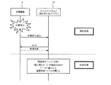
図5はホームゲートウェイ11の通知待ち受けアプリケーション7の初期化動作を示すフローチャート、図6はその動作によるデータの通信手順を示す図である。これらの図5及び図6において、通知待ち受けアプリケーション7は、通信部20を起動してから(S201)、NTP(Network Time Protocol)サーバにアクセスして現在時刻を取得する(S202)。
(Initialization operation of notification standby application 7 (part 1))
FIG. 5 is a flowchart showing an initialization operation of the
続けて、サブネットワーク2に接続された家電機器4のデータベース構築のため、接続されている家電機器4を確認する(S203)。つまり、サブネットワーク2内に起動通知を送信し、その応答から起動中のサービス対応の家電機器4を確認する。
ここで、家電機器4は、外部に通知可能な異常フラグを有しており、異常状態を外部に通知する場合は、自己の異常フラグをOFFからONに変更し、異常フラグの状態変化通知を行うようになっている。このようにONした異常フラグは、後述するようにホームゲートウェイ2が異常通知を受け取った後に、ホームゲートウェイ2によりOFFされるようになっている。
Subsequently, in order to construct a database of the
Here, the
ところで、例えば停電などが起き、家電機器4やホームゲートウェイ11の電源を再投入しなければならなくなった場合、家電機器4の電源投入後、家電機器4に異常が発生し、その後にホームゲートウェイ11の電源が投入されることがある。この場合、家電機器4は、異常フラグをONすることにより異常発生通知をホームゲートウェイ11に通知するものの、ホームゲートウェイ11の電源が投入されていないため、異常フラグをOFFに戻す初期化要求がなされない。このため、その後にホームゲートウェイ11の電源が投入されて起動し、通知待ち受けアプリケーション7が起動されたとしても、異常が発生した家電機器4からの異常通知を受け取ることができなくなってしまう。
By the way, for example, when a power failure occurs and the
そこで、本実施例では、ホームゲートウェイ11は、電源投入により起動したときは、起動している家電機器4を検出し(S203:あり)、検出した家電機器4全てに対して、初期化要求を発行し(S204)、その後の異常通知が正常に行えるようにしている。
続けて、通知待ち受けアプリケーション7は、状態変化通知部17を起動することにより家電機器4からの状態変化データを受信可能としてから(S205)、待機状態に移行して次のイベントが発生するのを監視する(S206)。
Therefore, in this embodiment, when the
Subsequently, the
また、通知待ち受けアプリケーション7は、図5において、起動している家電機器4を確認した結果、見つからなかった場合は(S203:NO)、待機状態に移行し(S207)、データベースに基づいてサービス対象の家電機器4が現在起動しているかを判別し、その状態変化を待ち受ける(S208)。これは、存在していない家電機器4の待ち受けを常に行ってしまうと、既に使われていない古い家電機器4なども待ち受けることになり、負荷が大きくなるため、選別しているのである。
Further, if the
そして、通知待ち受けアプリケーション7は、待機中に、新規の家電機器4が起動したことの通知を受けた場合は(S208:あり)、接続している家電機器4に対して初期化要求を出力すると共に(S209)、状態変化通知受信部24を起動してから(S210)、待機状態に移行して次のイベントが発生するのを監視する(S206)。
Then, the
(家電機器4の初期化動作)
家電機器4は、図4に示す待機中に、外部要求があったときは(S107:YES)、要求種別を判断する(S108)。この場合、要求種別は、初期化であるので(S108:初期化)、状態変更(初期化)を実行する(S110)。つまり、異常フラグがONしているときはOFFするもので、初期化処理したことをホームゲートウェイ11に応答してから、待機状態に移行して次のイベントが発生するのを監視する(S106)。
(Initialization operation of home appliance 4)
When there is an external request during the standby shown in FIG. 4 (S107: YES), the
(通知待ち受けアプリケーション7の初期化動作(その2)
本実施例のホームゲートウェイ11では、複数の家電機器4を同じ通知待ち受けアプリケーション7で監視するため、家電機器4が異常状態となった場合に通知する異常フラグを共通としている。つまり、共通の異常フラグがONとなるのを監視している。
しかしながら、家電機器4に二種類の異常が連続して発生した場合には、家電機器4が二番目の異常を通知するために異常通知フラグをONしようとするにしても、既にONとなっているため、二番目の異常通知をホームゲートウェイ11に通知することができない。
そこで、通知待ち受けアプリケーション7は、家電機器4から異常通知を受けたときは、当該家電機器4の異常通知をOFFするようになっている。これにより、家電機器4は、次の異常をホームゲートウェイに通知することが可能となる。
(Initialization operation of notification standby application 7 (part 2)
In the
However, when two types of abnormality occur in the
Therefore, the
(家電機器4の状態変化通知動作)
家電機器4は、自身の状態を随時記録しており、図4に示すように待機中に状態が変化した場合には(S103:YES)、状態内容を保存すると共に(S104)、その状態変化をサブネットワーク2を通じて通知してから(S105)、待機状態に移行して次のイベントが発生するのを監視する(S106)。この場合、状態変化の通知の形態は同一のものを使用し、各家電機器4それぞれに対応した情報を利用する。この場合の通知形態が同一とは、家電機器4が機器名、またはMACアドレスなどを付加した同じ内容の状態変化通知を行うことを意味するものである。これは、通知待ち受けアプリケーション7を家電機器4の機種毎に別アプリケーションとして起動させると、ホームゲートウェイ11に大きな負荷がかかることから、ホームゲートウェイ11が機器毎の区別をして取得する必要性をなくし、一つの通知待ち受けアプリケーション7で待ち受け状態を実現するためである。
(State change notification operation of home appliance 4)
The
(通知待ち受けアプリケーション7の状態変化受信動作)
図7はホームゲートウェイ11の各アプリケーションの待機中におけるイベント発生時の動作を示すフローチャート、図8は通知待ち受けアプリケーションの動作によるデータの通信手順を示す図である。これらの図7及び図8において、通知待ち受けアプリケーション7は、待機中に(S301)、家電機器4から状態変化の通知を受けたときは(S302:YES)、その通知に含まれるIPアドレスやMACアドレスから自分自身のデータベースを参照し、機器名など固有のデータを取得し、状態変化通知の種類によって通知をした家電機器4に対して現在の状態の取得要求を発行することにより何が変化したかを問合せる(S303)。例えば、家電機器4が冷蔵庫の場合は、冷蔵庫の扉の開閉通知を受取った場合には、通知元の家電機器4に対して製造番号の問合せを行う。
(
FIG. 7 is a flowchart showing an operation when an event occurs while each application of the
(家電機器4の外部要求処理動作)
家電機器4は、図4に示すように待機中に外部要求を受けたときは(S107:YES)、その外部要求の種別を判断する(S108)。この場合、外部要求は取得要求であるので(S108:取得)、状態内容をサブネットワーク2に通知してから(S109)、待機状態に移行する(S106)。
(External request processing operation of home appliance 4)
When the
(通知待ち受けアプリケーション7の履歴保存動作)
通知待ち受けアプリケーション7は、図7に示すように状態内容を取得したときは(S304)、その状態内容を保存可能なデータに加工することにより一つの履歴保存ファイル10に追加保存してから(S305)、待機状態に移行して次のイベントが発生するのを監視する(S306)。この履歴保存ファイル10にはサブネットワーク2に接続された家電機器4の様々な状態変化履歴が保存されており、新しい通知が行われるたびに追加保存される。この保存される通知データには、通知時刻、機種名、メーカ名、固有アドレス、製造番号などをひとまとまりのデータとして保存し、履歴情報として利用可能な形態で保存される。
(History saving operation of notification standby application 7)
As shown in FIG. 7, when the
図9は、履歴保存ファイル10の一例を示している。この図9において、履歴保存ファイル10のデータとしては、時刻、機器コード、変化箇所、変化内容、型名、製造番号、MACアドレスが登録可能となっている。
FIG. 9 shows an example of the
(保存情報通知アプリケーション8のアプリ初期化動作)
図10は、ホームゲートウェイ11の保存情報通知アプリケーション8と情報サーバ6とのデータの通信手順を示す図である。この図10において、保存情報通知アプリケーション8は、電源ONに応じて自動起動したときは、アプリ初期化処理を実行してサービス登録確認する。つまり、情報サーバ6にサービス対象として登録されていなかった場合は、情報サーバ6に対してサービス対象の要求を発行する。この場合、システムを購入または利用するユーザは、ホームゲートウェイ11と同じサブネットワーク2内に存在するホーム端末5から、ホームゲートウェイ11を通じて情報サーバ6にアクセスすることによって、サービス開始の登録を行うことができる。このとき、ホームゲートウェイ11自身が所属するサブネットワーク2内からアクセスする場合、ホームゲートウェイ11にログインしてから情報サーバ6にアクセスすることによって、サービス開始の登録を行うことができる。
(Application initialization operation of the stored information notification application 8)
FIG. 10 is a diagram showing a data communication procedure between the stored
(保存情報通知アプリケーション8の状態通知動作)
保存情報通知アプリケーション8は、上述のようにしてアプリ初期化処理が終了したときは、図7に示す待機状態に移行する(S301)。この待機中においては、保存情報通知アプリケーション8は、待ち受け処理を実行する(図10参照)。
ところで、家電機器4の状態が変化する毎に、情報サーバ6へそのことを通知したのでは、情報サーバ6に大きな負荷が掛かる。
(Status notification operation of the stored information notification application 8)
When the application initialization process is completed as described above, the saved
By the way, every time the state of the
そこで、保存情報通知アプリケーション8は、所定時刻となったときは(S307:YES)、ランダムまたは機器固有の固有時間待機してから(S308)、保存された履歴保存ファイル10をHTTPを用いて情報サーバ6へ送信する(S309)。これにより、情報サーバ6の負荷の軽減を図ることができる。
ここで、保存情報通知アプリケーション8が固有の通知待機時間を持っているのは、例えばホームゲートウェイ11に保存されている履歴保存ファイル10を通知する時間間隔を一日6時間とすると、一日に一つの家庭から4回の通知が行われることになる。この時間間隔は、前述したようにホームゲートウェイ11が起動した際にNTPサーバから取得した現在時刻に基づいて、全ての家庭のホームゲートウェイ11から、決まった時刻に通知することになる。
Therefore, when the predetermined time is reached (S307: YES), the storage
Here, the storage
このようにホームゲートウェイ11から決まった時刻から送信する場合、情報サーバ6では、通知される時刻に基づいてホームゲートウェイ11からの通知データが何れの時間帯の動作履歴データを含むのかを知ることができることから、これを利用して、図11に示すように家電機器4が冷蔵庫の場合、冷蔵庫の扉開閉の回数を通知される動作履歴データの通知時間をわざわざ確認しなくても済むようになる。
Thus, when transmitting from the time determined from the
しかしながら、NTPサーバを用いると、各家庭から同時刻に情報サーバ6へのアクセスが集中するため、情報サーバ6の負荷が極めて大きくなることが予測される。このため、保存情報通知アプリケーション8は、待ち受け処理を実行する場合は、家電機器4固有の待機時間を設け、指定通知時刻から所定の待機時間だけ待った後に、情報サーバ6へ通知を行う。つまり、図10に示すように動作開始まで一定時間待機した後、さらに固有の時間だけ待機するのである。この待機時間は、製品毎に固有なMACアドレスや、製造番号などの固有番号から作成され、機器毎にランダムな数値に設定される。このようなランダムな数値を作成する方法としては、MACアドレスや製造番号の数値の一部或いは全部を不定要素として乱数作成関数により作成してもよいし、リングカウンタを不定期なタイミングで停止することにより作成するようにしてもよい。
However, when an NTP server is used, access to the
また、保存情報通知アプリケーション8は、情報サーバ6への通知データの容量が大きくなることによるメモリのオーバーフローを防ぐため、送信した履歴保存ファイル10を消去してから(S310)、待機状態に移行して次のイベントが発生するのを監視する(S306)。ここで、履歴保存ファイル10を消去する際に家電機器4から通知が行われた場合、通知データに二重アクセスが生じる危険性があるため、通知データの送信後、通知データに自身以外からのアクセスがないことを確認して通知データの消去を行い、逆にアクセスがある場合には、アクセスがなくなった後に消去を行うようにしている。
In addition, the storage
(情報サーバ6の動作)
情報サーバ6は、ホームゲートウェイ11から受信された通知データを機種別、開いた扉別(冷蔵庫の場合)、時間別などに分けて格納し、クライアント端末14から閲覧要求があった場合は、そのクライアント端末14に対してデータを送信する。これにより、図11に示すようにクライアント端末14に冷蔵庫の扉の開閉回数が時間帯に対応して表示されるので、ユーザは、家電機器4の状態変化を遠隔地から確認することができる。
(Operation of information server 6)
The
(現在情報通知アプリケーション9の動作)
ところで、上述したように情報サーバ6の負荷の軽減を図るために、状態変化通知をホームゲートウェイ11に一旦保存し、一定時間毎に通知するようなシステムを利用した場合、家電機器4の現在の状態を情報サーバ6で管理することは困難である。これは、通知データをホームゲートウェイ11内に一旦保存することにより、情報の即時性が失われてしまうからである。
(Operation of the current information notification application 9)
By the way, in order to reduce the load on the
そこで、本実施例では、情報の即時性を失わないシステムを構築するため、情報サーバ6へ通知するだけでなく、情報サーバ6から要求が行われた場合、ホームゲートウェイ11は、保存している状態変化通知の履歴情報をホームゲートウェイ11に送信することにより、最新の履歴情報をもって現在の状態とするようになっている。
図12は、このような動作を実現するための各機器のデータの通信手順を示す図である。この図12において、ユーザがクライアント端末14により宅外より宅内の家電機器4の状態を取得しようとした場合、情報サーバ6へアクセスして取得要求する。この場合、情報サーバ6には、所定時間間隔毎の履歴データが保存されているため、対象の家電機器4がどのように動作していたかを確認することができない。このため、情報サーバ6には各家庭のホームゲートウェイ11のIPアドレスや暗号鍵などの情報が予め保存されており、外部から現在の状態取得要求が行われた場合には、ユーザ名からデータベースに記憶された当該ユーザのホームゲートウェイ11を検索し、保存されているIPアドレスや暗号鍵を使用して接続し、ホームゲートウェイ11に保存されている履歴保存ファイル10の取得要求を行う。
Therefore, in this embodiment, in order to construct a system that does not lose the immediacy of information, the
FIG. 12 is a diagram showing a data communication procedure of each device for realizing such an operation. In FIG. 12, when the user tries to acquire the state of the home
ホームゲートウェイ11の現在情報通知アプリケーション9は、図7に示す待機中において(S301)、履歴情報取得要求があった場合は(S311:YES)、上述した保存情報通知アプリケーション8の通知方法と同様の通知方法を利用し、履歴保存ファイル10の送信を行う(S312)。この場合も、データの重複を避けるために、送信後に履歴保存ファイル10の削除を行ってから(S313)、待機状態に移行して次のイベントが発生するのを監視する(S306)。
The current
(情報サーバ6の動作)
情報サーバ6は、図12に示すように履歴保存ファイル10を受け取った後に、情報サーバ6内の情報を書き換ることにより、クライアント端末14に対して最新の情報を知らせることができ、これによりクライアント端末14は情報取得を完了することができる。従って、ユーザは、クライアント端末14により家電機器4の最新の状態変化を確認することができる。
(Operation of information server 6)
The
(ホームゲートウェイ11の履歴消去動作)
上述したように、ホームゲートウェイ11は、情報サーバ6からの要求に応じて必要な情報を通知した後、メモリ負荷を軽減するために履歴消去を行う。
ところで、履歴消去中に家電機器4の状態通知が行われた場合、その状態通知は情報サーバ6へ通知されないまま、消去されてしまう可能性がある。
(History deletion operation of home gateway 11)
As described above, the
By the way, when the status notification of the
そこで、動作履歴データを消去する最中には、履歴保存ファイル10へ他のプログラムがアクセスできないようにし、消去が終了した後に動作履歴データを書き込むようにする。また、履歴消去開始時に、他のプログラムがアクセスしている場合には、動作履歴データが保存されている最中である場合が考えられる。このようにアクセス終了時に消去を行ってしまうと、この場合も、動作履歴データが情報サーバ6へ通知されないまま消去されてしまう可能性があることから、消去する前に動作履歴データを情報サーバ6へ通知を行うことによって、動作履歴データの抜けを防止するようにしている。
Therefore, during the erasing of the operation history data, other programs cannot be accessed from the
このような実施例によれば、ホームゲートウェイ11は、家電機器4から状態変化通知を受け取ったときは、状態変化を示す動作履歴データを一つの履歴保存ファイル10に追加保存し、その履歴保存ファイル10を所定時刻となる毎に情報サーバ6に送信するようにしたので、家電機器から状態変化がある毎に情報サーバに状態変化を示すデータを送信する従来例のものと違って、ホームゲートウェイ11の負荷を大幅に低減することができる。また、このようにホームゲートウェイ11から情報サーバ6にアクセスする時間が一定である結果、情報サーバ6は、ホームゲートウェイ11からのアクセスされる時間のみ待ち受けプログラムを起動すればよいので、それだけ情報サーバ6の負荷を軽減することができる。
According to such an embodiment, when the
しかも、ホームゲートウェイ11は、履歴保存ファイル10を送信する際は、所定時刻から自己に割り当てられた固有番号に基づいて算出したランダムな時間だけ待機してから実行するようにしたので、ホームゲートウェイ11から情報サーバ6へのアクセスが集中することはなく、情報サーバ6の負荷を一層軽減することができる。
また、ユーザは、携帯電話機のようなクライアント端末14から情報サーバ6にアクセスすることによりホームゲートウェイ11に記憶されている最新の動作履歴データを確認することができるので、遠隔地から宅内の家電機器4の状態変化を所望のタイミングで監視することができる。
In addition, when transmitting the
Further, since the user can check the latest operation history data stored in the
本発明は、上記実施例に限定されることなく、次のように変形または拡張できる。
サブネットワーク2は、無線ネットワークに限られず、例えば電力線等を通信路として用いる有線ネットワーク等としてもよい。
ホームゲートウェイ11は、履歴保存ファイル10を起動した時刻から算出された一定時間毎に送るようにしてもよい。
情報サーバ6がホームゲートウェイ11に対して履歴保存ファイル10の送信時刻を設定するようにしてもよい。
The present invention is not limited to the above embodiment, but can be modified or expanded as follows.
The
The
The
図面中、2はサブネットワーク(構内ネットワーク)、3はインターネット(公衆ネットワーク)、4は家電機器、6は情報サーバ、11はホームゲートウェイ、14はクライアント端末である。 In the drawings, 2 is a sub-network (local network), 3 is the Internet (public network), 4 is a home appliance, 6 is an information server, 11 is a home gateway, and 14 is a client terminal.
Claims (8)
この家電機器から状態変化の通知を受け取ったときは、通知時間、対象機器など必要な動作履歴データをまとめた履歴保存ファイルに新規の動作履歴データを追加すると共に、所定タイミングで上記履歴保存ファイルを公衆ネットワークを通じて送信するホームゲートウェイと、
このホームゲートウェイから履歴保存ファイルを受信したときは、家電機器の状態変化の動作履歴データを顧客に対応して管理する情報サーバとを備えた家電機器の状態変化管理システム。 Home appliances that are connected to the local network wirelessly or by wire, and that notify the status change in the local network when a status change occurs,
When a notification of a state change is received from this home appliance, new operation history data is added to a history storage file that summarizes necessary operation history data such as notification time and target device, and the history storage file is added at a predetermined timing. A home gateway that transmits through a public network;
A home appliance state change management system comprising an information server that manages the operation history data of the home appliance state change corresponding to the customer when a history storage file is received from the home gateway.
前記ホームゲートウェイは、外部から取得要求されたときは、少なくとも最新の動作履歴データを送信し、
前記情報サーバは、前記クライアント端末から最新のデータを要求されたときは、前記ホームゲートウェイに取得要求することにより最新の動作履歴データを取得してから、当該動作履歴データを前記クライアント端末に送信し、
前記クライアント端末は、前記情報サーバから取得した動作履歴データを表示することを特徴とする請求項1ないし3の何れかに記載の家電機器の状態変化管理システム。 Comprising a client terminal accessible to the information server;
The home gateway sends at least the latest operation history data when an external acquisition request is made,
When the latest data is requested from the client terminal, the information server acquires the latest operation history data by making an acquisition request to the home gateway, and then transmits the operation history data to the client terminal. ,
The state change management system for home appliances according to any one of claims 1 to 3, wherein the client terminal displays operation history data acquired from the information server.
前記ホームゲートウェイは、異常フラグの状態変化通知を受け取った場合は、異常処理を実行した後、前記家電機器の異常フラグをOFFすることを特徴とする請求項1ないし4の何れかに記載の家電機器の状態変化管理システム。 The home appliance has an abnormality flag for notifying the outside of the abnormality, and when an abnormal state occurs, the abnormality flag state change notification is performed by turning on the abnormality flag,
5. The home appliance according to claim 1, wherein when the home gateway receives an abnormality flag state change notification, the home gateway turns off the abnormality flag of the home appliance after executing the abnormality process. 6. Equipment state change management system.
When erasing the operation history data, the home gateway is executed in a state in which access from the other program to the history storage file is prohibited. The state change management system for home electric appliances according to claim 7, wherein operation history data is notified to the information server.
Priority Applications (1)
| Application Number | Priority Date | Filing Date | Title |
|---|---|---|---|
| JP2004053761A JP2005244753A (en) | 2004-02-27 | 2004-02-27 | State change management system of household electric devices |
Applications Claiming Priority (1)
| Application Number | Priority Date | Filing Date | Title |
|---|---|---|---|
| JP2004053761A JP2005244753A (en) | 2004-02-27 | 2004-02-27 | State change management system of household electric devices |
Publications (2)
| Publication Number | Publication Date |
|---|---|
| JP2005244753A true JP2005244753A (en) | 2005-09-08 |
| JP2005244753A5 JP2005244753A5 (en) | 2007-03-22 |
Family
ID=35025971
Family Applications (1)
| Application Number | Title | Priority Date | Filing Date |
|---|---|---|---|
| JP2004053761A Pending JP2005244753A (en) | 2004-02-27 | 2004-02-27 | State change management system of household electric devices |
Country Status (1)
| Country | Link |
|---|---|
| JP (1) | JP2005244753A (en) |
Cited By (12)
| Publication number | Priority date | Publication date | Assignee | Title |
|---|---|---|---|---|
| JP2007299368A (en) * | 2006-04-03 | 2007-11-15 | Seiko Epson Corp | Monitoring apparatus and monitoring method of device connected to network |
| JP2008046934A (en) * | 2006-08-17 | 2008-02-28 | Toshiba Corp | Household electrical appliance network system |
| JP2008098939A (en) * | 2006-10-11 | 2008-04-24 | Nippon Telegr & Teleph Corp <Ntt> | Connection controller, connection control method and connection control program |
| JP2010527475A (en) * | 2007-06-29 | 2010-08-12 | 中国移▲動▼通信集▲団▼公司 | Information appliance data storage system and data processing method |
| JP2012059188A (en) * | 2010-09-13 | 2012-03-22 | Traffic Shimu:Kk | Monitoring network, program, and recording medium |
| WO2012160861A1 (en) * | 2011-05-24 | 2012-11-29 | 日本電気株式会社 | Software automatic deployment device |
| WO2013058312A1 (en) * | 2011-10-18 | 2013-04-25 | ガイアホールディングス株式会社 | Household appliance information accumulation server |
| KR101288877B1 (en) | 2006-09-20 | 2013-07-23 | 에스케이텔레콤 주식회사 | Power saving type home management system and home system and home server and operating methods thereof |
| JP2015082669A (en) * | 2013-10-21 | 2015-04-27 | 三菱電機株式会社 | Apparatus control system |
| JP2015179952A (en) * | 2014-03-19 | 2015-10-08 | シャープ株式会社 | Control system, hems controller, and control method |
| JP2016123105A (en) * | 2012-09-27 | 2016-07-07 | 京セラ株式会社 | Management system, management method and apparatus |
| JP2017505084A (en) * | 2014-11-21 | 2017-02-09 | 小米科技有限責任公司Xiaomi Inc. | Task setting method, apparatus, program, and recording medium |
-
2004
- 2004-02-27 JP JP2004053761A patent/JP2005244753A/en active Pending
Cited By (16)
| Publication number | Priority date | Publication date | Assignee | Title |
|---|---|---|---|---|
| JP2007299368A (en) * | 2006-04-03 | 2007-11-15 | Seiko Epson Corp | Monitoring apparatus and monitoring method of device connected to network |
| JP2008046934A (en) * | 2006-08-17 | 2008-02-28 | Toshiba Corp | Household electrical appliance network system |
| KR101288877B1 (en) | 2006-09-20 | 2013-07-23 | 에스케이텔레콤 주식회사 | Power saving type home management system and home system and home server and operating methods thereof |
| JP4641301B2 (en) * | 2006-10-11 | 2011-03-02 | 日本電信電話株式会社 | Connection control device, connection control method, and connection control program |
| JP2008098939A (en) * | 2006-10-11 | 2008-04-24 | Nippon Telegr & Teleph Corp <Ntt> | Connection controller, connection control method and connection control program |
| JP2010527475A (en) * | 2007-06-29 | 2010-08-12 | 中国移▲動▼通信集▲団▼公司 | Information appliance data storage system and data processing method |
| JP2012059188A (en) * | 2010-09-13 | 2012-03-22 | Traffic Shimu:Kk | Monitoring network, program, and recording medium |
| WO2012160861A1 (en) * | 2011-05-24 | 2012-11-29 | 日本電気株式会社 | Software automatic deployment device |
| JPWO2012160861A1 (en) * | 2011-05-24 | 2014-07-31 | 日本電気株式会社 | Software automatic deployment device |
| WO2013058312A1 (en) * | 2011-10-18 | 2013-04-25 | ガイアホールディングス株式会社 | Household appliance information accumulation server |
| JP2016123105A (en) * | 2012-09-27 | 2016-07-07 | 京セラ株式会社 | Management system, management method and apparatus |
| US9774711B2 (en) | 2012-09-27 | 2017-09-26 | Kyocera Corporation | Management system, management method and equipment |
| JP2018026843A (en) * | 2012-09-27 | 2018-02-15 | 京セラ株式会社 | Management system, management method, and apparatus |
| JP2015082669A (en) * | 2013-10-21 | 2015-04-27 | 三菱電機株式会社 | Apparatus control system |
| JP2015179952A (en) * | 2014-03-19 | 2015-10-08 | シャープ株式会社 | Control system, hems controller, and control method |
| JP2017505084A (en) * | 2014-11-21 | 2017-02-09 | 小米科技有限責任公司Xiaomi Inc. | Task setting method, apparatus, program, and recording medium |
Similar Documents
| Publication | Publication Date | Title |
|---|---|---|
| US7516187B2 (en) | Remote control system for home appliance network and method for operating the same | |
| JP2006236353A (en) | Method of monitoring and controlling devices with instant messaging | |
| JP2007535190A (en) | Communication network system and communication device | |
| JP2004288187A (en) | Management device of equipment information via network and its method | |
| JP2005244753A (en) | State change management system of household electric devices | |
| JP5827697B2 (en) | Method, service gateway, and remote management server for naming sensor devices in a local network | |
| JP5974931B2 (en) | Communication device | |
| JP2006352666A (en) | Network household electric appliance control system | |
| CN104662848A (en) | Methods and systems for dynamic domain name system (ddns) | |
| JP4854412B2 (en) | Communication control device and communication control method | |
| CN104410530A (en) | Method of finding and utilizing MAC address to manage industrial switches | |
| JP2006509391A (en) | Using configuration identifiers to communicate configuration descriptions | |
| JP6085962B2 (en) | Management apparatus and address management method | |
| JP4799005B2 (en) | Information processing device | |
| JP2004258809A (en) | Middleware for information appliance network | |
| JP5173604B2 (en) | Gateway device | |
| US9086880B2 (en) | Communication device management apparatus, user device, and service device | |
| JP2005157603A (en) | State information providing device and method, computer program for the same, recording medium with the program stored, and computer programmed by the program | |
| JP2010004344A (en) | Method, device, system, and program for conducting remote accessing | |
| JP2005227825A (en) | Instrument monitoring controller | |
| JP5650816B1 (en) | COMMUNICATION SYSTEM, COMMUNICATION DEVICE, COMMUNICATION METHOD, AND PROGRAM | |
| Wang et al. | A toolkit for building dependable and extensible home networking applications | |
| JP2007174404A (en) | Position information system | |
| JP5135422B2 (en) | Gateway device | |
| EP2999162A1 (en) | Remote management of LAN devices by an Auto-Configuration Server |
Legal Events
| Date | Code | Title | Description |
|---|---|---|---|
| A521 | Written amendment |
Free format text: JAPANESE INTERMEDIATE CODE: A523 Effective date: 20070130 |
|
| A621 | Written request for application examination |
Free format text: JAPANESE INTERMEDIATE CODE: A621 Effective date: 20070130 |
|
| A977 | Report on retrieval |
Free format text: JAPANESE INTERMEDIATE CODE: A971007 Effective date: 20081219 |
|
| A131 | Notification of reasons for refusal |
Free format text: JAPANESE INTERMEDIATE CODE: A131 Effective date: 20090106 |
|
| A131 | Notification of reasons for refusal |
Free format text: JAPANESE INTERMEDIATE CODE: A131 Effective date: 20091117 |
|
| A02 | Decision of refusal |
Free format text: JAPANESE INTERMEDIATE CODE: A02 Effective date: 20100309 |