JP2005242564A - Management device, network system, communication interval control method and program - Google Patents
Management device, network system, communication interval control method and program Download PDFInfo
- Publication number
- JP2005242564A JP2005242564A JP2004049859A JP2004049859A JP2005242564A JP 2005242564 A JP2005242564 A JP 2005242564A JP 2004049859 A JP2004049859 A JP 2004049859A JP 2004049859 A JP2004049859 A JP 2004049859A JP 2005242564 A JP2005242564 A JP 2005242564A
- Authority
- JP
- Japan
- Prior art keywords
- communication interval
- communication
- copying machine
- managed
- managed device
- Prior art date
- Legal status (The legal status is an assumption and is not a legal conclusion. Google has not performed a legal analysis and makes no representation as to the accuracy of the status listed.)
- Pending
Links
Images
Landscapes
- Computer And Data Communications (AREA)
- Accessory Devices And Overall Control Thereof (AREA)
- Control Or Security For Electrophotography (AREA)
Abstract
Description
本発明は、複数の画像形成装置の稼動状況を管理する場合に適用される管理装置、ネットワークシステム、通信間隔制御方法、及びプログラムに関する。 The present invention relates to a management apparatus, a network system, a communication interval control method, and a program that are applied when managing the operation status of a plurality of image forming apparatuses.
従来、複写機やプリンタなどの画像形成装置をLAN(Local Area Network)などに接続して使用するシステムを構築し、LAN経由で通信を行うことで複写や印刷を行う形態がある。このようなシステムにおいては、複数の画像形成装置を管理するために、管理用のホストマシンが設置される。ホストマシンは、LANに接続された複数の画像形成装置の稼働情報を所定の時間間隔で収集し、画像形成装置が現在どのような状態にあるのかをリアルタイムに把握することができる。また、画像形成装置にて発生した障害の通知も収集することで、障害に対処することができる(例えば、特許文献1参照)。
ところで、上記システムにおける画像形成装置において障害が発生した場合、ホストマシン側では、ある程度の期間できるだけ詳細に画像形成装置の稼働状態を把握できることが望ましい。そのためには、画像形成装置の稼働情報を収集する際の上記所定の時間間隔を縮めて、よりきめ細かく稼働情報を収集する必要がある。しかし、稼働情報を収集する際の時間間隔を単純に縮めることは、ネットワークのトラフィックやホストマシン側での通信負荷の増大に繋がるため好ましくないという問題がある。 By the way, when a failure occurs in the image forming apparatus in the above system, it is desirable that the host machine side can grasp the operating state of the image forming apparatus in as much detail as possible for a certain period. For this purpose, it is necessary to collect the operation information more finely by reducing the predetermined time interval when collecting the operation information of the image forming apparatus. However, simply shortening the time interval when collecting the operation information is not preferable because it leads to an increase in network traffic and a communication load on the host machine side.
本発明の目的は、ネットワークのトラフィックや管理装置側での通信負荷を増大させることなく、特定の画像形成装置との間の通信頻度を上げることで、画像形成装置のより詳細な稼働情報を取得することを可能とした管理装置、ネットワークシステム、通信間隔制御方法、及びプログラムを提供することにある。 An object of the present invention is to obtain more detailed operation information of an image forming apparatus by increasing the frequency of communication with a specific image forming apparatus without increasing the network traffic or the communication load on the management apparatus side. The present invention provides a management apparatus, a network system, a communication interval control method, and a program that can be performed.
上述の目的を達成するために、本発明の管理装置は、複数の被管理装置を管理する管理装置であって、前記複数の被管理装置との間で情報の授受を行う通信手段と、特定の状態となった被管理装置が発生した場合、前記特定の状態となった被管理装置との間で情報の授受を行う際の通信間隔を早めると共に、前記特定の状態となった被管理装置以外の所定の被管理装置との間で情報の授受を行う際の通信間隔を遅くする制御手段とを備えることを特徴とする。 In order to achieve the above-described object, the management device of the present invention is a management device that manages a plurality of managed devices, and a communication unit that exchanges information with the plurality of managed devices; When a managed device that has entered the specified state occurs, the communication interval for sending and receiving information to and from the managed device that has reached the specific state is increased, and the managed device that has reached the specific state Control means for delaying a communication interval when information is exchanged with a predetermined managed device other than the above.
また、本発明の管理装置は、前記制御手段は、前記特定の状態となった被管理装置との間で情報の授受を定期的に行う際の通信間隔を、現在の通信間隔より短い第1の通信間隔に変更すると共に、前記特定の状態となった被管理装置以外の所定の被管理装置との間で情報の授受を定期的に行う際の通信間隔を、現在の通信間隔より長い第2の通信間隔に変更することを特徴とする。 In the management device according to the present invention, the control unit may be configured to set a communication interval for periodically exchanging information with the managed device in the specific state, which is shorter than a current communication interval. And the communication interval for periodically exchanging information with a predetermined managed device other than the managed device in the specific state is longer than the current communication interval. The communication interval is changed to 2.
また、本発明の管理装置は、前記制御手段は、前記特定の状態となった被管理装置に対し、変更した通信間隔を変更前の通信間隔に戻す日時である通信間隔復帰日時に達するまで前記第1の通信間隔で通信を行うよう指示を出し、前記特定の状態となった被管理装置以外の前記所定の被管理装置に対し、前記通信間隔復帰日時に達するまで前記第2の通信間隔で通信を行うよう指示を出すことを特徴とする。 In the management apparatus of the present invention, the control means until the communication interval return date / time is reached, which is a date / time for returning the changed communication interval to the communication interval before the change for the managed device in the specific state. An instruction is given to perform communication at the first communication interval, and the predetermined managed device other than the managed device in the specific state is sent at the second communication interval until the communication interval return date and time is reached. It is characterized by issuing an instruction to perform communication.
また、本発明の管理装置は、前記複数の被管理装置にそれぞれ設定された通信優先順位を記憶する記憶手段を備え、前記制御手段は、前記特定の状態となった被管理装置以外の前記所定の被管理装置として、前記記憶手段に記憶された通信優先順位が低い被管理装置を選定することを特徴とする。 In addition, the management device of the present invention includes storage means for storing the communication priority set for each of the plurality of managed devices, and the control means is the predetermined device other than the managed device in the specific state. As the managed device, a managed device having a low communication priority stored in the storage means is selected.
また、本発明の管理装置は、前記第2の通信間隔に変更する被管理装置の台数は、前記第1の通信間隔に変更する被管理装置の通信頻度の増加分が、前記第2の通信間隔に変更する被管理装置の通信頻度の減少分で少なくとも打ち消し可能な台数であることを特徴とする。 In the management device of the present invention, the number of managed devices to be changed to the second communication interval is equal to the increase in communication frequency of the managed device to be changed to the first communication interval. The number of devices that can be canceled at least by the decrease in the communication frequency of the managed device to be changed to the interval is characterized.
また、本発明の管理装置は、前記被管理装置とは、用紙に画像を形成する画像形成装置であり、前記特定の状態とは、前記画像形成装置の機構に障害が発生した状態、前記画像形成装置で用紙詰まりが発生した状態、前記画像形成装置が新規に設置された状態を含むことを特徴とする。 In the management apparatus of the present invention, the managed apparatus is an image forming apparatus that forms an image on a sheet, and the specific state is a state in which a failure has occurred in a mechanism of the image forming apparatus, and the image It includes a state in which a paper jam has occurred in the forming apparatus, and a state in which the image forming apparatus is newly installed.
上述の目的を達成するために、本発明のネットワークシステムは、前記何れかの管理装置と複数の被管理装置とをネットワークを介して通信可能に接続したことを特徴とする。 In order to achieve the above object, a network system according to the present invention is characterized in that any one of the management devices and a plurality of managed devices are communicably connected via a network.
更に、本発明は、前記管理装置がインターネットを介して前記複数の被管理装置を管理すると共に、前記複数の画像形成装置から前記管理装置に対し、累積画像形成枚数や画像形成装置の機構の作動回数等のカウンタ値を示す稼動情報を定期的に電子メールで送信し、障害発生や用紙詰まり多発等を示す異常状態情報を不定期的に電子メールで送信する構成としてもよい。 Further, according to the present invention, the management device manages the plurality of managed devices via the Internet, and the cumulative number of images formed from the plurality of image forming devices to the management device and the operation of the mechanism of the image forming device. The operation information indicating the counter value such as the number of times may be periodically transmitted by e-mail, and the abnormal state information indicating the occurrence of a failure or frequent paper jams may be transmitted by e-mail irregularly.
更に、本発明は、前記管理装置の前記記憶手段は、前記複数の画像形成装置にそれぞれ設定された通信優先順位と、前記複数の画像形成装置から前記管理装置に対し定期的に前記稼動情報を送信する際の通信間隔と、前記通信間隔復帰日時とを、前記複数の画像形成装置のそれぞれの識別番号に対応付けて記憶する構成としてもよい。 Further, according to the present invention, the storage unit of the management apparatus stores the communication priority set for each of the plurality of image forming apparatuses and the operation information from the plurality of image forming apparatuses to the management apparatus periodically. The communication interval at the time of transmission and the communication interval return date and time may be stored in association with the identification numbers of the plurality of image forming apparatuses.
本発明によれば、特定の状態となった被管理装置との間で情報の授受を行う際の通信間隔を早めると共に、特定の状態となった被管理装置以外の所定の被管理装置との間で情報の授受を行う際の通信間隔を遅くするため、特定の状態となった被管理装置の情報をよりきめ細かく取得することが可能となると共に、管理装置の通信負荷の増大を防ぐことができる。 According to the present invention, the communication interval when transferring information to and from a managed device that has entered a specific state is advanced, and a predetermined managed device other than the managed device that has entered a specific state Since the communication interval when transferring information between them is delayed, it is possible to obtain more detailed information on the managed device in a specific state, and to prevent an increase in the communication load of the management device it can.
また、本発明によれば、特定の状態となった被管理装置との間で情報の授受を定期的に行う際の通信間隔を、現在の通信間隔より短い第1の通信間隔に変更すると共に、特定の状態となった被管理装置以外の所定の被管理装置との間で情報の授受を定期的に行う際の通信間隔を、現在の通信間隔より長い第2の通信間隔に変更するため、上記同様に、特定の状態となった被管理装置の情報をよりきめ細かく取得することが可能となると共に、管理装置の通信負荷の増大を防ぐことができる。 In addition, according to the present invention, the communication interval when periodically exchanging information with the managed device in a specific state is changed to the first communication interval shorter than the current communication interval. In order to change the communication interval when periodically exchanging information with a predetermined managed device other than the managed device in a specific state to a second communication interval longer than the current communication interval Similarly to the above, it is possible to obtain more detailed information on the managed device in a specific state, and to prevent an increase in the communication load of the management device.
また、本発明によれば、特定の状態となった被管理装置に対し、変更した通信間隔を変更前の通信間隔に戻す日時である通信間隔復帰日時に達するまで第1の通信間隔で通信を行うよう指示を出し、特定の状態となった被管理装置以外の所定の被管理装置に対し、通信間隔復帰日時に達するまで第2の通信間隔で通信を行うよう指示を出すため、特定の状態となった被管理装置の稼働情報をよりきめ細かく取得することが可能となり、当該被管理装置の特定の状態となった個所や原因の特定、特定の状態の発生傾向の把握、特定の状態からの復旧などに役立てることができる。また、管理装置の通信負荷の増大を防ぐことができる。 In addition, according to the present invention, the managed device in a specific state is communicated at the first communication interval until reaching the communication interval return date and time that is the date and time for returning the changed communication interval to the communication interval before the change. In order to instruct the predetermined managed device other than the managed device in a specific state to perform communication at the second communication interval until the communication interval return date and time is reached. It is possible to obtain more detailed information about the operation of the managed device, and identify the location and cause of the managed device, identify the trend of occurrence of the specific status, It can be used for recovery. In addition, an increase in the communication load of the management apparatus can be prevented.
また、本発明によれば、特定の状態となった被管理装置以外の所定の被管理装置、即ち通信間隔を遅くする被管理装置として、通信優先順位が低い被管理装置を選定するため、通信間隔を遅くする被管理装置と管理装置との間の通信に支障を来たすことはない。 In addition, according to the present invention, a communication device is selected to select a managed device with a low communication priority as a predetermined managed device other than the managed device in a specific state, that is, a managed device that delays the communication interval. Communication between the managed device and the management device that slows down the interval will not be hindered.
また、本発明によれば、第2の通信間隔に変更する被管理装置の台数は、第1の通信間隔に変更する被管理装置の通信頻度の増加分が、第2の通信間隔に変更する被管理装置の通信頻度の減少分で少なくとも打ち消し可能な台数であるため、管理装置に対する通信負荷が増大しないように保つことができる。 According to the present invention, the number of managed devices to be changed to the second communication interval is changed to the second communication interval by an increase in the communication frequency of the managed device to be changed to the first communication interval. Since the number of managed devices is the number that can be canceled at least by the decrease in the communication frequency, the communication load on the management device can be kept from increasing.
また、本発明によれば、被管理装置とは、画像形成装置であり、特定の状態とは、画像形成装置の機構に障害が発生した状態、画像形成装置で用紙詰まりが発生した状態、画像形成装置が新規に設置された状態を含むため、機構に障害が発生した画像形成装置、或いは用紙詰まりが発生した画像形成装置、或いは新規に設置された画像形成装置の稼働情報をよりきめ細かく取得することが可能となり、当該画像形成装置の障害などの発生個所や原因の特定、障害などの発生傾向の把握、障害復旧などに役立てることができる。 Further, according to the present invention, the managed apparatus is an image forming apparatus, and the specific state is a state in which a failure has occurred in the mechanism of the image forming apparatus, a state in which a paper jam has occurred in the image forming apparatus, an image Since the image forming apparatus includes a newly installed state, the operation information of the image forming apparatus in which the mechanism has failed, the image forming apparatus in which the paper jam has occurred, or the newly installed image forming apparatus is obtained more finely. This makes it possible to identify the location and cause of the failure of the image forming apparatus, grasp the tendency of occurrence of the failure, and recover from the failure.
また、本発明によれば、ネットワークシステムは、前記何れかの管理装置と複数の被管理装置とをネットワークを介して通信可能に接続した構成であるため、ネットワークのトラフィックや管理装置側での通信負荷を増大させることなく、特定の画像形成装置との間の通信頻度を上げることで、特定の画像形成装置のより詳細な稼働情報を取得することが可能となり、画像形成装置の稼動状態をきめ細かく把握して的確な対処を行うことが可能となる。 In addition, according to the present invention, the network system has a configuration in which any one of the management devices and a plurality of managed devices are communicably connected via a network, so network traffic and communication on the management device side By increasing the frequency of communication with a specific image forming apparatus without increasing the load, it becomes possible to acquire more detailed operating information of the specific image forming apparatus, and finely control the operating state of the image forming apparatus. It is possible to grasp and take appropriate measures.
以下、本発明の実施の形態を図面に基づき説明する。 Hereinafter, embodiments of the present invention will be described with reference to the drawings.
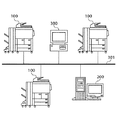
図1は、本実施の形態に係るデジタル複写機(以下、複写機と略称)とホストマシンとのイントラネット内における接続関係を示す概略図である。 FIG. 1 is a schematic diagram showing a connection relationship in the intranet between a digital copying machine (hereinafter abbreviated as copying machine) and a host machine according to the present embodiment.
図1において、被管理装置である複数台の複写機100、管理装置であるホストマシン200、一般のユーザが業務等で使用するパーソナルコンピュータ(以下、PCと略称)300が、LAN301を介して相互に接続されている。尚、上記複数台の複写機には便宜上同じ符号100を付すものとし、また、LAN301に対する複写機100やPC300の接続台数は任意である。
In FIG. 1, a plurality of
ホストマシン200と複写機100とは、LAN301を介して定常的に所定の時間間隔(以下、初期通信間隔という)で通信を行い、複写機100の稼働情報(後述)を複写機100からホストマシン200へ通知する。また、複写機100においてハードウエア障害やジャム(用紙詰まり)多発等の特定の事象が発生した場合(以下、この状態を異常状態という)には、即座にその事象内容を複写機100からホストマシン200へ通知する。更に、ある複写機100が異常状態に陥った際に、ホストマシン200と当該複写機100とが初期通信間隔より短い通信間隔で通信を行うことで、ホストマシン200が当該複写機100の稼働情報をよりきめ細かく取得して障害復旧等に役立てている。
The
但し、ホストマシン200と異常状態に陥った複写機100との通信間隔を単純に短くすると、ホストマシン200の処理負荷の増大を招いてしまう。そこで、ホストマシン200が異常状態に陥った複写機100と初期通信間隔より短い間隔で通信を行う一方で、異常状態にない別の複写機100との通信間隔を初期通信間隔より広げることも行うことで、ホストマシン200の処理負荷の増大を防いでいる。
However, if the communication interval between the
ホストマシン200と複写機100との間の通信形態としては、SNMP(Simple Network Management Protocol)を介したMIB(Management Information Base)のやり取りを行う通信形態や、SMTP(Simple Mail Transfer Protocol)を介した電子メールのやり取りを行う通信形態等がある。本実施の形態では後者の通信形態を用いた場合について説明する。
As a communication mode between the
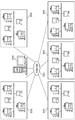
図2は、複写機100とホストマシン200とのインターネットを介した接続関係を示す概略図である。
FIG. 2 is a schematic diagram showing a connection relationship between the
図2において、複写機100とPC300とをLAN301を介して相互に接続することで、イントラネットの環境300を構成している。更に、これら複数のイントラネットの環境303とホストマシン200とをインターネット302を介して相互に接続することで、ネットワークシステムを構成している。また、ホストマシン200と複写機100とは、例えば、SMTPを介して電子メールをやり取りする通信形態をとっている。尚、上記複数のイントラネットの環境には便宜上同じ符号303を付すものとする。
In FIG. 2, an
ホストマシン200と複写機100との通信の仕方は、上記図1で説明したものと同じである。しかし、複数のイントラネット環境303内に存在する個々の複写機100と1台のホストマシン200とが通信することになるため、ホストマシン200側から見た通信相手先の複写機100の台数は図1の場合と比べて遥かに多くなる(例えば数万〜数十万台)。従って、上述した通信の仕方(異常状態に陥った複写機100と異常状態にない複写機100とのそれぞれで通信間隔を変更)によって、ホストマシン200の通信負荷の増大を防ぐことがより重要になる。
The manner of communication between the
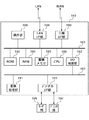
図3は、複写機100の制御部180の構成を示すブロック図である。
FIG. 3 is a block diagram illustrating a configuration of the
図3において、複写機100の制御部180は、システムバス181、画像バス182、ROM183、RAM184、蓄積メモリ185、CPU186、I/O制御部187、操作部188、LAN I/F部189、回線I/F部190、画像処理部191、デジタルI/F部193を備えている。また、複写機100は、原稿から画像を読み取るリーダ部196、用紙に画像を形成するプリンタ197を備えている。
3, the
制御部180の上記各構成要素は、システムバス181及び画像バス182に接続されている。 ROM183には、複写機100の制御プログラムが格納されており、CPU186により実行される。RAM184は、制御プログラムを実行するためのワークメモリエリアと、画像データを一時記憶するための画像メモリエリアを備える。蓄積メモリ185は、不揮発性メモリであり、複写機100の再起動後も保持しておく必要のある各種動作モード設定や、カウンタ値、稼働ログなどを記憶する。
Each component of the
LAN I/F部189は、LANと接続するためのインタフェース部であり、LANを介してホストマシン200と通信を行う。回線I/F部190は、WAN(Wide Area Network)であるISDN(Integrated Services Digital Network)や公衆電話網に接続され、ROM183内の通信制御プログラムにより制御され、ISDN I/Fやモデム、NCU(Network Control Unit)を介して遠隔のホストマシン200等の装置とデータの送受信を行う。操作部188には、表示部やキー入力部が内蔵されており、これらはCPU186により制御される。操作者は、操作部188のキー入力部を介して、リーダ部196のスキャナによる原稿読み取りやプリンタ部197のプリント出力に関する各種設定指示と、作動/停止指示を行う。
The LAN I /
以上のデバイス(ROM183〜回線I/F部190)がシステムバス181上に配置される。 I/O制御部197は、信号の送受信を行うシステムバス181と画像データを高速で転送する画像バス182とを接続するためのバスブリッジである。
The above devices (
画像バス182上には以下のデバイスが配置される。デジタルI/F部193は、リーダ部196やプリンタ部197と制御部180とを接続し、画像データの同期系/非同期系の変換を行う。また、リーダ部196やプリンタ部197内の各所に配置された各種センサ(不図示)が検出した情報は、このデジタルI/F部193及びI/O制御部197を介してシステムバス181へ送出される。画像処理部191は、リーダ部196からの入力画像データ及びプリンタ部197に対する出力画像データに対し補正/加工/編集を行う。
The following devices are arranged on the
CPU186は、該CPU186で実行される制御プログラムにより、初期通信間隔で蓄積メモリ185内のカウンタ値や稼働ログなどを読み出して電子メールデータに加工し、LAN I/F部189を介してホストマシン200へ送信する。この際の初期通信間隔や電子メール送信先アドレスは、蓄積メモリ185内に予め格納されている。
The
また、CPU186は、システムバス181上に送出された上記各種センサが検出した情報を受けて複写機100が異常状態に陥ったことを認識すると、その異常状態に陥ったことを示す情報とカウンタ値や稼働ログなどを同様に電子メールデータに加工してホストマシン200へ送信する。更に、CPU186は、後述する通信間隔の変更指示をホストマシン200から受けると、その指示内容を蓄積メモリ185内へ格納すると共に、同時に指示された所定の日時(以後、通信間隔復帰日時)に達するまで変更後の通信間隔で上記電子メールの送信を行う。
When the
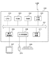
図4は、ホストマシン200の構成を示すブロック図である。
FIG. 4 is a block diagram showing the configuration of the
図4において、ホストマシン200は、例えばパーソナルコンピュータから構成されており、システムバス201、CPU202、ROM203、RAM204、LAN I/F部205、表示制御部206、入力制御部208、記憶装置211を内蔵したコンピュータ本体と、コンピュータ本体に接続されたディスプレイ207、キーボード209、マウス210とを備えている。
In FIG. 4, the
CPU202は、ホストマシン200全体を制御するものであり、記憶装置211に格納された制御プログラムに基づき図8〜図11のフローチャートに示す処理を実行する。ROM203は、システム起動に必要なブートプログラムを記憶するための読み出し専用メモリである。RAM204は、CPU202で制御プログラムを実行する際に使用される作業メモリである。LAN I/F部205は、LANを介して複写機100と通信を行うものであり、複写機100から通知される後述する稼動情報や異常状態を表す情報の受信等を行う。
The
表示制御部206は、ディスプレイ207に複写機100との通信内容などを表示する。入力制御部208は、ホストマシン200を管理するオペレータによるキーボード209/マウス210からの入力を受け付ける。記憶装置211は、磁気ディスク等から構成されており、CPU202により実行される上記制御プログラム、後述する通信管理テーブル500、複写機100から通知された稼働情報などを格納する。
A
ホストマシン200は、複写機100から送信される定期的な稼働情報の通知や、不定期的な複写機100の異常状態を表す情報の通知を常時受信している。
The
複写機100からホストマシン200に定期的に通知される稼働情報には、後述する各種カウンタ値、ジャム履歴、稼働ログなどが含まれており、複写機100を所有している顧客に対して毎月請求する定期メンテナンス料を算出したり、異常状態にある複写機100を集中的に監視したりするために使用される。ホストマシン200は、この稼働情報を記憶装置211に逐次格納する。一方、オペレータは、記憶装置211に格納された稼働情報をディスプレイ207を通じて適宜参照することにより、顧客への請求額を決定する。
The operation information periodically notified from the copying
複写機100からホストマシン200に不定期的に通知される複写機100の異常状態を表す情報には、稼働情報に加えて、複写機100で発生したハードウエア障害やジャムなどのエラー/アラーム情報が含まれている。ホストマシン200は、この異常状態を表す情報を記憶装置211に逐次格納すると共にディスプレイ207上に表示することで、複写機100が異常状態に陥っている旨をオペレータに通知する。一方、オペレータは、ディスプレイ207上の表示内容から複写機100の状態を判断し、必要に応じて複写機100の障害復旧作業をサービスマンに指示したり、トナーなどの消耗品を顧客に送付したりする。
The information indicating the abnormal state of the copying
ホストマシン200は、複写機100から不定期的な異常状態の通知を受けた場合、異常状態にある複写機100に対して、通信間隔復帰日時に達するまで初期通信間隔より短い通信間隔で定期的な稼働情報通知を行うよう指示を出す。この指示により、以後の当該複写機100の稼働情報をよりきめ細かく取得することが可能となり、当該複写機100の障害などの発生個所や原因の特定、発生傾向の把握、障害復旧などに非常に役立つ。
When the
また同時に、ホストマシン200は、異常状態にない別の複写機100に対して、通信間隔復帰日時に達するまで初期通信間隔より長い通信間隔で定期的な稼働情報通知を行うよう指示を出す。この指示により、ホストマシン200の処理負荷の増大を防ぐ。これらの指示の送出先の複写機100を選択する方法については後述する。
At the same time, the
本実施の形態における、複写機100がホストマシン200に対して定期的または不定期的に通知する情報内容には、以下に示すものが含まれる(不図示)。尚、各情報は、実際にはXML(Extensible Markup Language)形式で表現された上で更に暗号化され、電子メールデータとして複写機100からホストマシン200へ通知される。
The information content that the copying
複写機IDは、個々の複写機100を一意に特定するために予め複写機側に割り振られた番号である。データ送信日時は、複写機100からホストマシン200に電子メールを送信する時点の日時である。通信種別は、この通知が定期的なものであるか或いは不定期的なものであるかを表す識別子である。トータルカウンタは、複写機100におけるプリント枚数を合計したトータルプリント枚数であり、トータルジャムカウンタは、複写機100で発生したジャムの総回数である。
The copying machine ID is a number assigned to the copying machine side in advance to uniquely identify each copying
エラー/アラーム情報は、複写機100で発生したエラー/アラームの内容を表すエラー/アラームコードと、その発生日時とを含む。複写機100が定期的に情報を通知する場合、このエラー/アラームコードと発生日時は省かれる。ジャム履歴(1)は、複写機100で最近に発生したジャムに関する情報であり、以降発生日時の新しい順に並べた例えば過去19回分のジャムに関する情報としてジャム履歴(2)〜(20)がある。個々のジャム履歴は、ジャムの発生個所を表すジャムコードと、その発生日時と、ジャムが発生した時点でのトータルカウンタとを含む。
The error / alarm information includes an error / alarm code indicating the content of the error / alarm that has occurred in the copying
カウンタ情報は、複写機100内部で保持している各種課金カウンタの値であり、トナーの種類(C(シアン)/M(マゼンタ)/Y(イエロー)/K(ブラック))に応じたカウンタ値であるトナー別カウンタと、給紙カセットの種類に応じたカウンタ値であるカセット別カウンタと、モードの種類(カラーコピー/白黒コピー/片面コピー/両面コピー/プリントなど)に応じたカウンタ情報であるモード別カウンタと、用紙の種類に応じたカウンタ情報である用紙別カウンタと、複写機100で原稿をスキャンした回数であるスキャンカウンタとを含む。
The counter information is the value of various charging counters held in the copying
ファームウェアバージョンは、複写機100の制御ソフトウェアのバージョンである。メカカウンタは、複写機100内部で保持している各種機構部品の動作カウンタの値であり、複写機100が電子写真方式の場合は感光体ドラムの回転数や露光ランプの点灯回数、複写機100の給紙/排紙ローラを用紙が通過した回数である通紙回数、複写機100に付設される後処理装置(例えば、画像形成が完了した用紙を折るZ折り機)の作動回数などがカウンタ(1)、カウンタ(2)・・・として含まれる。稼動ログは、この通知を行う時点で複写機100内部に保持しているユーザ操作ログや制御ソフトウェアが生成するデバッグログなどである。
The firmware version is a control software version of the copying
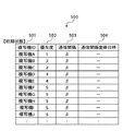
図5は、通信管理テーブル500の構成を模式的に示す図である。 FIG. 5 is a diagram schematically showing the configuration of the communication management table 500.
図5において、通信管理テーブル500は、ホストマシン200の記憶装置211内に保持されており、ホストマシン200と複数の複写機100との間の通信状況を管理するためのものである。ホストマシン200は、ホストマシン200の通信負荷の増大を防ぐべく、この通信管理テーブル500を参照しながら複写機100との通信間隔の調整を行う。尚、具体的な調整方法については後述する。
In FIG. 5, a communication management table 500 is held in the
通信管理テーブル500は、全ての複写機100がホストマシン200と初期通信間隔で通信している時の内容を表している。複写機ID501は、個々の複写機100を一意に特定するために予め複写機側に割り振られた番号であり、上述した複写機IDと同じものである。本実施の形態では、複写機ID501の値として「複写機A」「複写機B」・・・という記述をしているが、あくまでこれは便宜上のことであり、実際には個々の複写機100を一意に特定可能な番号が格納されている。
The communication management table 500 shows the contents when all the copying
優先度502は、複写機毎の通信優先度を示し、例えばレベル1〜5(通信優先度の順位:1>2>3>4>5)の5段階の何れかの値が個々の複写機ID501毎に設定される。ホストマシン200を管理するオペレータは、複写機100が新規に顧客先へ設置された時点で、キーボード209やマウス210を操作して通信管理テーブル500に複写機ID501を登録する。また、オペレータは、同時に優先度502の設定も行う。設定する優先度502は、複写機100の機種、複写機100の稼動率の予測、顧客情報などを基にオペレータが判断する。
The
通信間隔503は、複写機100がホストマシン200に対して定期的に稼動情報を通知する際の通信時間間隔である。本実施の形態では、通信間隔503の値として「α」「β」「γ」という記述をしているが、あくまでこれは便宜上のことであり、実際には例えば3600(秒)などの数値が格納されている。通信間隔復帰日時504は、ホストマシン200が複写機100に対して通信間隔の変更を指示する際に同時に指示する日時であり、複写機100が変更した通信間隔を初期通信間隔に戻す日時である。
The
通信間隔の定義は、以下の通りである。複写機100とホストマシン200の初期通信間隔はβ、異常状態にある複写機100に対してホストマシン200が指示する通信間隔はα、ホストマシン200の処理負荷の増大を防ぐために異常状態にない複写機100に対してホストマシン200が指示する通信間隔はγである。
The definition of the communication interval is as follows. The initial communication interval between the copying
本実施の形態では、αはβの1/2の値としているため、通信間隔αの複写機100は初期通信間隔βの複写機100の2倍の通信頻度で稼動情報をホストマシン200に通知することになり、ホストマシン200に与える通信負荷は高くなる。一方、γはβの2倍の値としているため、通信間隔γの複写機100は初期通信間隔βの複写機100の1/2倍の通信頻度で稼動情報をホストマシン200に通知することになり、ホストマシン200に与える通信負荷は低くなる。
In this embodiment, since α is a value that is 1/2 of β, the copying
異常状態にある複写機100の通信間隔をαに変更しつつホストマシン200にかかる通信負荷の増大を防ぐためには、全ての複写機100からホストマシン200への通信頻度が増大しないように保つことが必要である。即ち、通信間隔をβからαに変更した複写機100の通信頻度の増加分が、通信間隔をβからγに変更した複写機100の通信頻度の減少分によって少なくとも打ち消されるように調整することが必要である。
In order to prevent an increase in communication load on the
このため、本実施の形態では、1台の複写機100の通信間隔をβからαに変更する際、同時に例えば2台の複写機100の通信間隔をγに変更する例を想定する。尚、この際の通信間隔をγに変更する2台の複写機100として、通信管理テーブル500内の先頭から順に下記の検索条件に合致するものを検索する。
For this reason, in this embodiment, when changing the communication interval of one copying
・現在の通信間隔がβの複写機
・通信間隔をαに変更する複写機の優先度502以下の複写機
・優先度ができるだけ低い複写機
次に、上記構成を有する本実施の形態のネットワークシステムにおける動作について図6乃至図11を参照しながら詳細に説明する。
・ Copying machine with current communication interval β ・ Copying machine with
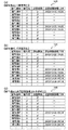
図6は、ある複写機が異常状態に陥った際の通信管理テーブルの内容の遷移を示す図であり、(a)は複写機Aにて障害が発生した場合の通信管理テーブル、(b)は複写機Fにて障害が発生した場合の通信管理テーブル、(c)は現在時刻が複写機Aの通信間隔復帰日時を過ぎた場合の通信管理テーブルである。 6A and 6B are diagrams showing the transition of the contents of the communication management table when a certain copying machine falls into an abnormal state. FIG. 6A is a communication management table when a failure occurs in the copying machine A. FIG. Is a communication management table when a failure occurs in the copying machine F, and (c) is a communication management table when the current time has passed the communication interval return date and time of the copying machine A.
図6において、全ての複写機100がホストマシン200と初期通信間隔βで通信している状態(通信管理テーブルが図5の500の状態)において、複写機Aが異常状態に陥った場合、ホストマシン200は複写機Aに対して通信間隔がα、通信間隔復帰日時が現在時刻の24時間後の「2003/12/25 19:35」で通信を行うように指示する。
In FIG. 6, when all the copying
また、複写機Aの優先度が1であることから、優先度が最低の5で通信間隔がβの複写機を図5の通信管理テーブル500の先頭から2台(複写機F、G)選定し、それらに対して通信間隔γ、通信間隔復帰日時が現在時刻の24時間後の「2003/12/25 19:35」で通信を行うように指示する。この指示内容を通信管理テーブルに反映した状態が図6(a)の520である。 Since the priority of the copying machine A is 1, two copying machines (copying machines F and G) having the lowest priority of 5 and the communication interval β are selected from the head of the communication management table 500 of FIG. Then, the communication interval γ and the communication interval return date and time are instructed to perform communication at “2003/12/25 19:35” 24 hours after the current time. The state in which this instruction content is reflected in the communication management table is 520 in FIG.
図6(b)の530は、更に複写機Fが異常状態に陥った場合の通信管理テーブルの状態を示している。ホストマシン200は複写機Fに対して通信間隔がα、通信間隔復帰日時が現在時刻の24時間後の「2003/12/26 09:14」で通信を行うように指示する。一方、複写機Fの通信間隔は障害発生直前までγであったため、全ての複写機100からホストマシン200への通信頻度を一定に保つためには、3台の複写機100の通信間隔をγに変更する必要がある。
そこで、複写機Fの優先度が5であることから、優先度が最低の5で通信間隔がβの複写機を図5の通信管理テーブル500の先頭から3台(複写機H、I、J)選定し、それらの複写機H、I、Jに対して通信間隔がγ、通信間隔復帰日時が現在時刻の24時間後の「2003/12/26 09:14」で通信を行うように指示する。 Therefore, since the priority of the copying machine F is 5, the three copying machines with the lowest priority of 5 and the communication interval β from the top of the communication management table 500 in FIG. 5 (copying machines H, I, J ) Select and instruct the copiers H, I, and J to communicate at “2003/12/26 09:14” 24 hours after the current time and the communication interval return date and time is γ. To do.
図6(c)の540は、現在時刻が複写機Aの通信間隔復帰日時「2003/12/25 19:35」を過ぎた場合の通信管理テーブルの状態を示している。ホストマシン200は、後述する図10・図11の処理フローに従って常時通信管理テーブル500の内容を監視している。そして、現在時刻が複写機Aの通信間隔復帰日時「2003/12/25 19:35」を過ぎた時点で、通信管理テーブル500内の複写機Aの通信間隔を初期通信間隔βに戻すと共に、通信間隔復帰日時をNULLに更新する。
更に、複写機Aの通信間隔を初期通信間隔βに戻したことに対応して、現在の通信間隔がγになっている2台の複写機の通信間隔も初期通信間隔βに戻すと共に、通信間隔復帰日時をNULLに更新する。この際の2台の複写機は、通信間隔復帰日時が古い順に通信管理テーブル500の先頭から選定する。従って、結果的に複写機Gと複写機Hが選定される。 Further, in response to returning the communication interval of the copying machine A to the initial communication interval β, the communication interval of the two copiers whose current communication interval is γ is also returned to the initial communication interval β, and communication is performed. The interval return date is updated to NULL. At this time, the two copiers are selected from the top of the communication management table 500 in order of the communication interval return date and time. Therefore, as a result, the copier G and the copier H are selected.
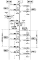
図7は、上記通信管理テーブル520の状態に至る前後における、複写機100及びホストマシン200間の通信シーケンスの一部を示す図である。
FIG. 7 is a diagram showing a part of a communication sequence between the copying
以下、この通信シーケンス図を参照しながら複写機100及びホストマシン200双方の処理の流れを説明する。
Hereinafter, the processing flow of both the copying
図7において、複写機Aは、初期通信間隔βごとに定期的に上述した稼動情報(デバイス情報)を電子メールでホストマシン200に通知している(ステップS601、ステップS603)。同様に、複写機Fも、初期通信間隔βごとに定期的に上述した稼動情報(デバイス情報)を電子メールでホストマシン200に通知している(ステップS602、ステップS604)。
In FIG. 7, the copying machine A periodically notifies the
その後、複写機Aで何らかの障害が発生して異常状態に陥ると(ステップS605)、複写機Aは障害が発生した旨をホストマシン200に通知する(ステップS606)。この障害発生通知を受けたホストマシン200は後述する負荷バランス判断処理(図8及び図9)を行い、管理している全ての複写機100の中から通信間隔を調整する対象の複写機を選定する(ステップS607)。そして、ホストマシン200は異常状態に陥った複写機Aの通信間隔を縮めるため、通信間隔復帰日時「2003/12/25 19:35」に達するまで通信間隔αで定期的な稼働情報通知を行うよう複写機Aに対して指示を出す(ステップS608)。
Thereafter, when some trouble occurs in the copying machine A and enters an abnormal state (step S605), the copying machine A notifies the
一方、ホストマシン200は異常状態にない複写機Fの通信間隔を広げるため、通信間隔復帰日時「2003/12/25 19:35」に達するまで通信間隔γで定期的な稼働情報通知を行うよう複写機Fに対して指示を出す(ステップS609)。尚、ホストマシン200は複写機Fに対して出した指示と同様の指示を複写機Gに対しても出すが、本通信シーケンス図では特に図示しない。
On the other hand, in order to increase the communication interval of the copying machine F that is not in an abnormal state, the
ホストマシン200からの上記指示を受けた複写機Aは、以後、通信間隔復帰日時「2003/12/25 19:35」に達するまで通信間隔αで定期的な稼働情報通知をホストマシン200に対して行う(ステップS610、ステップS612)。そして、通信間隔復帰日時「2003/12/25 19:35」に達した時点で、複写機Aは初期通信間隔βで定期的な稼働情報通知をホストマシン200に対して行うよう自らの動作を切り替える(ステップS614、ステップS616)。
Receiving the above instruction from the
また、ホストマシン200からの上記指示を受けた複写機Fも、以後、通信間隔復帰日時「2003/12/25 19:35」に達するまで通信間隔γで定期的な稼働情報通知をホストマシン200に対して行う(ステップS611、ステップS613)。そして、通信間隔復帰日時「2003/12/25 19:35」に達した時点で、複写機Fは初期通信間隔βで定期的な稼働情報通知をホストマシン200に対して行うよう自らの動作を切り替える(ステップS615、ステップS617)。
Further, the copier F that has received the above instruction from the
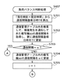
図8及び図9は、ホストマシン200の負荷バランス判断処理を示すフローチャートである。
8 and 9 are flowcharts illustrating the load balance determination process of the
該負荷バランス判断処理は、ホストマシン200にかかる通信負荷の増大を防ぐため、異常状態に陥った複写機が発生した場合、異常状態にない複写機の中から通信間隔を広げる(遅くする)複写機を検索し選定する処理である。
In the load balance determination process, in order to prevent an increase in the communication load on the
以下、上記図7の通信シーケンスを例にとりながら図8及び図9のフローチャートを参照し、ホストマシン200にかかる通信負荷を調整するための負荷バランス判断処理手順を説明する。
Hereinafter, the load balance determination processing procedure for adjusting the communication load applied to the
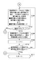
図8及び図9において、負荷バランス判断処理(ステップS607)では、先ず初めに、ホストマシン200のCPU202は、通信間隔復帰日時Tを算出し、「2003/12/25 19:35」という日時を得る(ステップS701)。この日時は、ホストマシン200内で予め設定している規定時間(本実施の形態では例えば24時間としている)を現在時刻に加えることで算出している。
8 and 9, in the load balance determination process (step S607), first, the
続いて、CPU202は、上記図5の通信管理テーブル500内を検索し、障害発生を通知してきた複写機(x)の通信間隔503を取得して通信間隔復帰日時504をTに更新する(ステップS702)。つまり、複写機Aの初期通信間隔βを取得し、通信間隔復帰日時を「2003/12/25 19:35」に更新する。そして、CPU202は、上記ステップS702で取得した通信間隔503がαであるか否かを判断する(ステップS703)。
Subsequently, the
取得した通知間隔がαである場合、即ち障害発生を通知してきた複写機(x)が以前から既に異常状態に陥っている複写機である場合には、CPU202は、そのまま負荷バランス判断処理を抜ける(ステップS711)。その後、CPU202は、通信管理テーブル500の更新を行った複写機(x)に対してのみ、通信間隔復帰日時Tに達するまで通信間隔αで定期的な稼働情報通知を行うように指示を出す。この指示を受けた複写機(x)は既に通信間隔αで通知を行っているため、実質的には通信間隔復帰日時の更新のみを行う。
If the acquired notification interval is α, that is, if the copier (x) that has notified the occurrence of a failure is a copier that has already entered an abnormal state, the
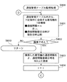
一方、取得した通知間隔がαではない場合には、CPU202は、通信管理テーブル500内の複写機(x)の通信間隔503をαに更新する(ステップS704)。つまり、複写機Aの通信間隔をαに更新する。続いて、CPU202は、ループカウンタiを1で初期化し(ステップS705)、ホストマシン200への通信頻度が増大しないように保つことを目的として、通信間隔をγに変更する複写機(i)を通信管理テーブル500内から1台検索(選定)する(ステップS706)。この際の検索条件は上述した通りである(複写機(x) の優先順位≧複写機(i)の優先順位、且つ、複写機(i)の通信間隔=β)。
On the other hand, if the acquired notification interval is not α, the
検索条件に合致する複写機(i)を検索できた場合には(ステップS707でYES)、CPU202は、通信管理テーブル500内の複写機(i)の通信間隔503をγに、通信間隔復帰日時504をTに更新する(ステップS708)。つまり、複写機Fの通信間隔をγに、通信間隔復帰日時を「2003/12/25 19:35」に更新する。そして、CPU202は、ループカウンタiをインクリメントしつつ(ステップS709)、上記と同じ処理を繰り返す。これにより、CPU202は、複写機Fに続いて複写機Gを選定し、その通信間隔をγに、通信間隔復帰日時を「2003/12/25 19:35」に更新する。
If the copying machine (i) that matches the search condition can be searched (YES in step S707), the
そして、選定した複写機(i)が規定台数Nに達した時点で(ステップS710でYES)、負荷バランス判断処理を抜ける(ステップS711)。つまり、図7の通信シーケンスを例にとると、規定台数N(1台の複写機の通信間隔をβからαに変更する際、同時に通信間隔をγに変更する複写機の台数)は2なので、上記の複写機Fと複写機Gの2台の複写機を選定した時点で負荷バランス判断処理を抜ける。 When the selected copying machine (i) reaches the specified number N (YES in step S710), the load balance determination process is exited (step S711). In other words, taking the communication sequence of FIG. 7 as an example, the prescribed number N (the number of copiers that simultaneously changes the communication interval from γ when the communication interval of one copier is changed from β to α) is 2. When the two copying machines F and G are selected, the load balance determination process is exited.
その後、CPU202は、通信管理テーブル500の更新を行った複写機(x)及び複写機(i)に対して、通信間隔復帰日時Tに達するまでそれぞれ通信間隔α及びγで定期的な稼働情報通知を行うように指示を出す。つまり、複写機Aに対しては通信間隔復帰日時「2003/12/25 19:35」に達するまで通信間隔αで稼働情報通知を行うように指示し、複写機Fと複写機Gに対しては通信間隔復帰日時「2003/12/25 19:35」に達するまで通信間隔γで稼働情報通知を行うように指示する。
Thereafter, the
また、上記ループの最中において、上記検索条件に合致する複写機(i)の検索が規定台数Nに達する前にできなくなった場合(ステップS707でNO)、その時点で負荷バランス判断処理を抜ける(ステップS711)。 If the search for the copying machine (i) that matches the search condition cannot be performed before reaching the specified number N during the loop (NO in step S707), the load balance determination process is exited at that time. (Step S711).
図10及び図11は、ホストマシン200の通信管理テーブル監視処理を示すフローチャートである。
10 and 11 are flowcharts showing the communication management table monitoring process of the
該通信管理テーブル監視処理は、ホストマシン200が定期的に実行しており、上記図5の通信管理テーブル500内において現在時刻が通信間隔復帰日時を過ぎている複写機100の通信間隔や通信間隔復帰日時の更新を常時行っている。
The communication management table monitoring process is periodically executed by the
以下、上記図6(c)の通信管理テーブル540を例にとりながら図10及び図11のフローチャートを参照し、通信管理テーブル監視処理手順を説明する。 The communication management table monitoring processing procedure will be described below with reference to the flowcharts of FIGS. 10 and 11 taking the communication management table 540 of FIG. 6C as an example.
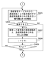
図10及び図11において、通信管理テーブル監視処理(ステップS800)では、先ず初めに、ホストマシン200のCPU202は、通信管理テーブル500内において検索条件(通信間隔がαで且つ現在時刻が通信間隔復帰日時を過ぎている)に合致する複写機を1台検索する(ステップS801)。この検索処理は、上記検索条件に合致する複写機が検索できている間(ステップS802)は繰り返し行い、検索できなくなった時点で通信管理テーブル監視処理を抜ける(ステップS810)。
10 and 11, in the communication management table monitoring process (step S800), first, the
上記検索条件に合致する複写機が検索できた場合、CPU202は、続いて通信管理テーブル500内における当該複写機(つまり複写機A)の通信間隔αを初期通信間隔β、通信間隔復帰日時をNULLに更新する(ステップS803)。続いて、CPU202は、ループカウンタiを1で初期化し(ステップS804)、上記ステップS803にて通信間隔をαから初期通信間隔βに戻したことに対応して、通信間隔をγから初期通信間隔βに戻す複写機(i)を通信管理テーブル500内から1台検索する(ステップS805)。尚、複写機(i)の検索にあたっては、通信間隔復帰日時が古い順に通信管理テーブルの先頭から検索する。
If a copy machine that matches the search conditions can be searched, the
上記検索条件に合致する複写機(i)が検索できた場合、CPU202は、通信管理テーブル500内の複写機(i)の通信間隔503をβに、通信間隔復帰日時504をNULLに更新する(ステップS807)。そして、CPU202は、ループカウンタiをインクリメントしつつ(ステップS808)、上記と同じ処理を繰り返す。但し、選定した複写機(i)が規定台数Nに達した時点で(ステップS809でYES)、ループを抜けてステップS801に戻る。上記図6(c)の通信管理テーブル540を例にとると規定台数Nは2なので、複写機Gと複写機Hの2台の複写機を選定し、それらの通信間隔をβ、通信間隔復帰日時をNULLに更新した時点でループを抜けてステップS801に戻る。
When the copying machine (i) that matches the search condition can be searched, the
また、上記ループの最中において、上記検索条件に合致する複写機(i)の検索が規定台数Nに達する前にできなくなった場合(ステップS806でNO)、その時点でループを抜けてステップS801に戻る。 In the middle of the loop, if the search for the copying machine (i) that matches the search condition cannot be performed before reaching the specified number N (NO in step S806), the loop is exited at that point and step S801 is executed. Return to.
以上説明したように、本実施の形態によれば、複数の複写機の稼働状況をネットワークを介してホストマシンから監視している環境において、ホストマシンは、異常状態に陥った複写機に対しては、通信間隔復帰日時に達するまで初期通信間隔より短い通信間隔で定期的な稼働情報通知を行うよう指示する。これにより、以後の当該複写機の稼働情報をよりきめ細かく取得することが可能となり、当該複写機の障害などの発生個所や原因の特定、障害などの発生傾向の把握、障害復旧などに非常に役立てることができる。 As described above, according to the present embodiment, in an environment where the operation status of a plurality of copying machines is monitored from a host machine via a network, the host machine can detect a copying machine that has entered an abnormal state. Instructs to periodically perform operation information notification at a communication interval shorter than the initial communication interval until the communication interval return date and time is reached. This makes it possible to obtain more detailed information on the operation of the copier thereafter, which is very useful for identifying the location and cause of the failure of the copier, understanding the tendency of the failure, and recovering from the failure. be able to.
また同時に、ホストマシンは、異常状態にない複写機に対しては、通信間隔復帰日時に達するまで初期通信間隔より長い通信間隔で定期的な稼働情報通知を行うよう指示する。これにより、ホストマシンの通信負荷の増大を防ぐことができる。 At the same time, the host machine instructs a copying machine that is not in an abnormal state to periodically notify operation information at a communication interval longer than the initial communication interval until the communication interval return date and time is reached. As a result, an increase in the communication load of the host machine can be prevented.
即ち、ネットワークのトラフィックやホストマシン側での通信負荷を増大させることなく、特定の(障害発生やジャム多発等の異常状態に陥った)複写機との間の通信頻度を上げることで、特定の複写機のより詳細な稼働情報を取得することが可能となり、複写機の稼動状態をきめ細かく把握して的確な対処(例えば障害復旧作業やメンテナンス作業をサービスマンに指示するなど)を行うことが可能となる。 In other words, without increasing the network traffic or communication load on the host machine side, increasing the frequency of communication with a specific copier (falling into an abnormal state such as failure or frequent jams) More detailed operation information of the copier can be acquired, and the operation status of the copier can be grasped in detail and appropriate measures can be taken (for example, instructing a service person to perform fault recovery work or maintenance work). It becomes.
[他の実施の形態]
上記実施の形態では、異常状態に陥った1台の複写機の通信間隔を初期通信間隔βより短い通信間隔αに変更する際、異常状態にない2台の複写機の通信間隔を初期通信間隔βより長い通信間隔γに変更する例を説明したが、本発明はこれに限定されるものではなく、初期通信間隔βより長い通信間隔γに変更する複写機の台数は、初期通信間隔βより短い通信間隔αに変更する複写機の通信頻度の増加分が、初期通信間隔βより長い通信間隔γに変更する複写機の通信頻度の減少分によって少なくとも打ち消し可能な台数であればよい。
[Other embodiments]
In the above embodiment, when the communication interval of one copier that has entered an abnormal state is changed to a communication interval α that is shorter than the initial communication interval β, the communication interval of two copiers that are not in an abnormal state is changed to the initial communication interval. Although an example of changing to a communication interval γ longer than β has been described, the present invention is not limited to this, and the number of copiers to be changed to a communication interval γ longer than the initial communication interval β is greater than the initial communication interval β. It is sufficient that the increase in the communication frequency of the copying machine changed to the short communication interval α is at least cancelable by the decrease in the communication frequency of the copying machine changed to the communication interval γ longer than the initial communication interval β.
上記実施の形態では、通信間隔αを初期通信間隔βの1/2の値とし、通信間隔γを初期通信間隔βの2倍の値とした例を説明したが、本発明はこれに限定されるものではなく、通信間隔αを初期通信間隔βの1/Nの値とし、通信間隔γを初期通信間隔βのN倍の値(N≧3)としてもよい。この場合は、通信間隔γに変更する複写機の台数は上記実施の形態の場合(2台)よりも多い(通信頻度の増加分を通信頻度の減少分によって打ち消し可能な)台数となる。
In the above embodiment, an example has been described in which the communication interval α is set to a value that is ½ of the initial communication interval β, and the communication interval γ is set to a value that is twice the initial communication interval β. However, the present invention is not limited to this. Instead, the communication interval α may be a
上記実施の形態では、複写機が異常状態(ハードウエア障害やジャム多発等)に陥った場合に当該複写機の通信間隔を初期通信間隔βより短い通信間隔αに変更する例を説明したが、本発明はこれに限定されるものではなく、複写機を新規に設置しネットワークに接続した場合に、当該複写機の設置後の稼動状況を観察するため、当該複写機の通信間隔を初期通信間隔βより短い通信間隔αに変更するようにしてもよい。 In the above embodiment, an example has been described in which the communication interval of the copying machine is changed to a communication interval α shorter than the initial communication interval β when the copying machine enters an abnormal state (such as hardware failure or frequent jams). The present invention is not limited to this, and when a copying machine is newly installed and connected to the network, the communication interval of the copying machine is set to the initial communication interval in order to observe the operation status after the copying machine is installed. The communication interval α may be shorter than β.
上記実施の形態では、複写機の画像形成方式については特に言及しなかったが、本発明は特定の画像形成方式に限定されるものではなく、電子写真方式、インクジェット方式など各種の画像形成方式に適用可能である。 In the above embodiment, the image forming method of the copying machine is not particularly mentioned, but the present invention is not limited to a specific image forming method, and various image forming methods such as an electrophotographic method and an ink jet method are used. Applicable.
上記実施の形態では、被管理装置を複写機とした例を説明したが、本発明は複写機のみへの適用に限定されるものではなく、複合機やプリンタなどの他の装置にも適用可能である。 In the above embodiment, an example in which a managed device is a copying machine has been described. However, the present invention is not limited to application only to a copying machine, and can be applied to other devices such as a multifunction machine and a printer. It is.
本発明は、上述した実施の形態の機能を実現するソフトウェアのプログラム(図8〜図11のフローチャート)をコンピュータ又はCPUに供給し、そのコンピュータ又はCPUが該供給されたプログラムを読出して実行することによって、達成することができる。 The present invention supplies a software program (flowcharts in FIGS. 8 to 11) that realizes the functions of the above-described embodiments to a computer or CPU, and the computer or CPU reads and executes the supplied program. Can be achieved.
この場合、上記プログラムは、該プログラムを記録した記憶媒体から直接供給されるか、又はインターネット、商用ネットワーク、若しくはローカルエリアネットワーク等に接続される不図示の他のコンピュータやデータベース等からダウンロードすることにより供給される。 In this case, the program is directly supplied from a storage medium storing the program, or downloaded from another computer or database (not shown) connected to the Internet, a commercial network, a local area network, or the like. Supplied.
上記プログラムの形態は、オブジェクトコード、インタプリタにより実行されるプログラムコード、OS(オペレーティングシステム)に供給されるスクリプトデータ等の形態から成ってもよい。 The form of the program may be in the form of object code, program code executed by an interpreter, script data supplied to an OS (operating system), and the like.
また、本発明は、上述した実施の形態の機能を実現するソフトウェアのプログラムを記憶した記憶媒体をコンピュータ又はCPUに供給し、そのコンピュータ又はCPUが記憶媒体に記憶されたプログラムを読出して実行することによっても、達成することができる。 The present invention also supplies a computer or CPU with a storage medium storing a software program that implements the functions of the above-described embodiments, and the computer or CPU reads and executes the program stored in the storage medium. Can also be achieved.
この場合、格納媒体から読出されたプログラムコード自体が上述した各実施の形態の機能を実現すると共に、そのプログラムコードを記憶した記憶媒体は本発明を構成する。 In this case, the program code itself read from the storage medium realizes the functions of the above-described embodiments, and the storage medium storing the program code constitutes the present invention.
プログラムコードを記憶する記憶媒体としては、例えば、ROM、RAM、NV−RAM、フロッピー(登録商標)ディスク、ハードディスク、光ディスク(登録商標)、光磁気ディスク、CD−ROM、MO、CD−R、CD−RW、DVD−ROM、DVD−RAM、DVD−RW、DVD+RW、磁気テープ、不揮発性のメモリカード等がある。 As a storage medium for storing the program code, for example, ROM, RAM, NV-RAM, floppy (registered trademark) disk, hard disk, optical disk (registered trademark), magneto-optical disk, CD-ROM, MO, CD-R, CD -RW, DVD-ROM, DVD-RAM, DVD-RW, DVD + RW, magnetic tape, nonvolatile memory card, etc.
上述した実施の形態の機能は、コンピュータから読出されたプログラムコードを実行することによるばかりでなく、コンピュータ上で稼動するOS等がプログラムコードの指示に基づいて実際の処理の一部又は全部を行うことによっても実現することができる。 The function of the above-described embodiment is not only by executing the program code read from the computer, but the OS or the like running on the computer performs part or all of the actual processing based on the instruction of the program code. Can also be realized.
更に、本発明は、前述した実施の形態を実現するソフトウェアのプログラムがネットワーク上のデータベース又はホームページから通信プログラムによリーダウンロードされ、このプログラムを読出して実行することによって達成することができる。 Furthermore, the present invention can be achieved by downloading a software program for realizing the above-described embodiment from a database on a network or a homepage by a communication program, and reading and executing this program.
上記プログラムは、クライアントコンピュータのブラウザを用いてインターネットのホームページに接続し、該ホームページからコンピュータプログラム自体、又は自動インストール機能を含む圧縮ファイルをハードディスク等の記憶媒体にダウンロードすることによっても供給することができる。 The above program can also be supplied by connecting to a homepage on the Internet using a browser of a client computer and downloading the computer program itself or a compressed file including an automatic installation function from the homepage to a storage medium such as a hard disk. .
また、上記プログラムは、プログラムコードを暗号化した上で格納したCD−ROM等の記憶媒体をユーザに配布し、所定の条件をクリアしたユーザに対し、インターネットを介してホームページから暗号化を解く鍵情報をダウンロードさせ、その鍵情報を使用することにより暗号化されたプログラムコードを実行してコンピュータにインストールさせることによっても供給することができる。 The above program distributes a storage medium such as a CD-ROM stored after encrypting the program code to the user, and provides a key for decrypting the encryption from the homepage via the Internet to the user who has cleared a predetermined condition. It can also be provided by downloading the information and using the key information to execute the encrypted program code and install it on the computer.
上述した実施の形態の機能は、プログラムコードを複数のファイルに分割し、夫々のファイルを異なるホームページからダウンロードすることによっても実現することができる。即ち、本発明の機能処理をコンピュータで実現させるためのプログラムファイルを複数のユーザに対してダウンロードさせるWWWサーバも、本発明を構成する。 The functions of the embodiments described above can also be realized by dividing the program code into a plurality of files and downloading each file from a different home page. That is, a WWW server that allows a plurality of users to download a program file for realizing the functional processing of the present invention on a computer also constitutes the present invention.
また、上述した実施の形態の機能は、記憶媒体から読出されたプログラムが、コンピュータに挿入された機能拡張ボード又はコンピュータに接続された機能拡張ユニットに備えられたメモリに書込まれた後、そのプログラムの指示に基づき、その機能拡張ボード又は機能拡張ユニットに備えられたCPU又はMPU等が実際の処理の一部又は全部を実行することによっても実現することができる。 Further, the functions of the above-described embodiment are obtained by writing a program read from a storage medium into a function expansion board inserted in a computer or a memory provided in a function expansion unit connected to the computer, and It can also be realized by the CPU or MPU provided in the function expansion board or function expansion unit executing part or all of the actual processing based on the instructions of the program.
100 複写機(被管理装置に対応)
200 ホストマシン(管理装置に対応)
202 CPU(制御手段に対応)
205 LAN I/F部(通信手段に対応)
301 インターネット(ネットワークに対応)
302 イントラネット(ネットワークに対応)
500 通信管理テーブル(記憶手段に対応)
100 copier (supports managed devices)
200 Host machine (supports management devices)
202 CPU (corresponding to control means)
205 LAN I / F (corresponding to communication means)
301 Internet (supports network)
302 Intranet (supports network)
500 Communication management table (corresponding to storage means)
Claims (9)
前記複数の被管理装置との間で情報の授受を行う通信手段と、
特定の状態となった被管理装置が発生した場合、前記特定の状態となった被管理装置との間で情報の授受を行う際の通信間隔を早めると共に、前記特定の状態となった被管理装置以外の所定の被管理装置との間で情報の授受を行う際の通信間隔を遅くする制御手段とを備えることを特徴とする管理装置。 A management device that manages a plurality of managed devices,
Communication means for exchanging information with the plurality of managed devices;
When a managed device that has entered a specific state occurs, the communication interval for sending and receiving information to and from the managed device that has entered the specific state is increased, and the managed device that has entered the specific state A management device comprising: a control unit that delays a communication interval when information is exchanged with a predetermined managed device other than the device.
前記制御手段は、前記特定の状態となった被管理装置以外の前記所定の被管理装置として、前記記憶手段に記憶された通信優先順位が低い被管理装置を選定することを特徴とする請求項1記載の管理装置。 Storage means for storing communication priorities set for each of the plurality of managed devices,
The control unit selects a managed device having a low communication priority stored in the storage unit as the predetermined managed device other than the managed device in the specific state. The management apparatus according to 1.
前記特定の状態とは、前記画像形成装置の機構に障害が発生した状態、前記画像形成装置で用紙詰まりが発生した状態、前記画像形成装置が新規に設置された状態を含むことを特徴とする請求項1記載の管理装置。 The managed device is an image forming device that forms an image on paper,
The specific state includes a state where a failure has occurred in the mechanism of the image forming apparatus, a state where a paper jam has occurred in the image forming apparatus, and a state where the image forming apparatus is newly installed. The management apparatus according to claim 1.
特定の状態となった被管理装置が発生した場合、前記特定の状態となった被管理装置との間で情報の授受を行う際の通信間隔を早めると共に、前記特定の状態となった被管理装置以外の所定の被管理装置との間で情報の授受を行う際の通信間隔を遅くすることを特徴とする通信間隔制御方法。 A management device communication interval control method for managing a plurality of managed devices,
When a managed device that has entered a specific state occurs, the communication interval when sending and receiving information to and from the managed device that has entered the specific state is advanced, and the managed device that has entered the specific state A communication interval control method characterized by delaying a communication interval when exchanging information with a predetermined managed device other than the device.
前記複数の被管理装置との間で情報の授受を行う通信モジュールと、特定の状態となった被管理装置が発生した場合、前記特定の状態となった被管理装置との間で情報の授受を行う際の通信間隔を早めると共に、前記特定の状態となった被管理装置以外の所定の被管理装置との間で情報の授受を行う際の通信間隔を遅くする制御モジュールとを備えることを特徴とするプログラム。 A program that causes a computer to execute a communication interval control method for a management device that manages a plurality of managed devices,
When a communication module that exchanges information with the plurality of managed devices and a managed device that is in a specific state occurs, information is exchanged between the managed device that is in the specific state And a control module for delaying the communication interval when exchanging information with a predetermined managed device other than the managed device in the specific state. A featured program.
Priority Applications (1)
| Application Number | Priority Date | Filing Date | Title |
|---|---|---|---|
| JP2004049859A JP2005242564A (en) | 2004-02-25 | 2004-02-25 | Management device, network system, communication interval control method and program |
Applications Claiming Priority (1)
| Application Number | Priority Date | Filing Date | Title |
|---|---|---|---|
| JP2004049859A JP2005242564A (en) | 2004-02-25 | 2004-02-25 | Management device, network system, communication interval control method and program |
Publications (2)
| Publication Number | Publication Date |
|---|---|
| JP2005242564A true JP2005242564A (en) | 2005-09-08 |
| JP2005242564A5 JP2005242564A5 (en) | 2008-01-17 |
Family
ID=35024262
Family Applications (1)
| Application Number | Title | Priority Date | Filing Date |
|---|---|---|---|
| JP2004049859A Pending JP2005242564A (en) | 2004-02-25 | 2004-02-25 | Management device, network system, communication interval control method and program |
Country Status (1)
| Country | Link |
|---|---|
| JP (1) | JP2005242564A (en) |
Cited By (9)
| Publication number | Priority date | Publication date | Assignee | Title |
|---|---|---|---|---|
| JP2010218135A (en) * | 2009-03-16 | 2010-09-30 | Canon Inc | Management apparatus, management method, and program |
| JP2014149645A (en) * | 2013-01-31 | 2014-08-21 | Canon Inc | Information processing apparatus, information processing system, information processing method, program, and storage medium |
| JP2016021105A (en) * | 2014-07-14 | 2016-02-04 | コニカミノルタ株式会社 | Image forming apparatus |
| JP6064216B1 (en) * | 2015-11-12 | 2017-01-25 | 株式会社Pfu | Peripheral device management system, management device, and management method |
| US9602418B2 (en) | 2014-03-27 | 2017-03-21 | Fujitsu Limited | Apparatus and method for selecting a flow to be changed upon congestion occurrence |
| JP2017073068A (en) * | 2015-10-09 | 2017-04-13 | セイコーエプソン株式会社 | Network system and server |
| JP2017073069A (en) * | 2015-10-09 | 2017-04-13 | セイコーエプソン株式会社 | Network system and printer |
| JP2017092681A (en) * | 2015-11-09 | 2017-05-25 | セイコーエプソン株式会社 | Network system, client, and control method of client |
| US10362147B2 (en) | 2015-10-09 | 2019-07-23 | Seiko Epson Corporation | Network system and communication control method using calculated communication intervals |
-
2004
- 2004-02-25 JP JP2004049859A patent/JP2005242564A/en active Pending
Cited By (11)
| Publication number | Priority date | Publication date | Assignee | Title |
|---|---|---|---|---|
| JP2010218135A (en) * | 2009-03-16 | 2010-09-30 | Canon Inc | Management apparatus, management method, and program |
| JP2014149645A (en) * | 2013-01-31 | 2014-08-21 | Canon Inc | Information processing apparatus, information processing system, information processing method, program, and storage medium |
| US9602418B2 (en) | 2014-03-27 | 2017-03-21 | Fujitsu Limited | Apparatus and method for selecting a flow to be changed upon congestion occurrence |
| JP2016021105A (en) * | 2014-07-14 | 2016-02-04 | コニカミノルタ株式会社 | Image forming apparatus |
| JP2017073068A (en) * | 2015-10-09 | 2017-04-13 | セイコーエプソン株式会社 | Network system and server |
| JP2017073069A (en) * | 2015-10-09 | 2017-04-13 | セイコーエプソン株式会社 | Network system and printer |
| US10362147B2 (en) | 2015-10-09 | 2019-07-23 | Seiko Epson Corporation | Network system and communication control method using calculated communication intervals |
| JP2017092681A (en) * | 2015-11-09 | 2017-05-25 | セイコーエプソン株式会社 | Network system, client, and control method of client |
| JP6064216B1 (en) * | 2015-11-12 | 2017-01-25 | 株式会社Pfu | Peripheral device management system, management device, and management method |
| JP2017091311A (en) * | 2015-11-12 | 2017-05-25 | 株式会社Pfu | Peripheral device management system, management device and management method |
| US10102095B2 (en) | 2015-11-12 | 2018-10-16 | Pfu Limited | Peripheral management system, management device, and management method |
Similar Documents
| Publication | Publication Date | Title |
|---|---|---|
| USRE42166E1 (en) | Monitoring apparatus, management method and program therefor, and management apparatus and management method and program therefor | |
| JP3841023B2 (en) | Printer status notification system and notification terminal device | |
| US8051379B2 (en) | System, apparatus, method and computer readable storage medium for displaying information related to an image-forming apparatus connected to a network | |
| EP1237329B1 (en) | Method and device for network device status notification | |
| JP4182114B2 (en) | Image forming apparatus monitoring system, monitoring method and program | |
| US8799420B2 (en) | Remote management system | |
| JP4974837B2 (en) | Management device, image forming apparatus, component management method, storage medium, and program | |
| US20100088609A1 (en) | Management apparatus, image forming apparatus, and service processing method | |
| EP1930806B1 (en) | Monitoring apparatus, image forming apparatus, monitoring system, method of changing network setting, and program | |
| JP2008077315A (en) | Information processor and information processing method | |
| US8472044B2 (en) | Management apparatus and control method thereof | |
| US20040260803A1 (en) | Apparatus maintenance method, server computer for apparatus maintenance system, and electronic apparatus | |
| US9488947B2 (en) | Method and system for managing field convertible customer replaceable components | |
| US7882180B2 (en) | Monitoring apparatus for image forming apparatus, control method executed by the monitoring apparatus, program for implementing the control method, and management apparatus, control method executed by the management apparatus, and program for implementing the control method | |
| JP2005242564A (en) | Management device, network system, communication interval control method and program | |
| US20110128579A1 (en) | Printing system, printing apparatus, printing method, and storage medium | |
| US20100005352A1 (en) | Program transmission system, program transmission method, and storage medium storing control program | |
| JP2005305887A (en) | System and method for managing device information | |
| JP4408927B2 (en) | Image forming apparatus and information processing method | |
| US7072799B2 (en) | Information processing apparatus, maintenance managing method, program, and computer-readable storing medium | |
| US10592174B2 (en) | Information processing system, server and non-transitory computer-readable recording medium encoded with data distribution program | |
| JP6147092B2 (en) | Network system, control method, monitoring apparatus, and program | |
| US20080114876A1 (en) | Image forming apparatus and management system of image forming apparatus | |
| US20070288705A1 (en) | Information processing apparatus, management apparatus, and communication method | |
| US20040260978A1 (en) | Information collecting apparatus, rebooting method, program, and remote maintenance system |
Legal Events
| Date | Code | Title | Description |
|---|---|---|---|
| A621 | Written request for application examination |
Free format text: JAPANESE INTERMEDIATE CODE: A621 Effective date: 20050613 |
|
| RD03 | Notification of appointment of power of attorney |
Free format text: JAPANESE INTERMEDIATE CODE: A7423 Effective date: 20060418 |
|
| RD05 | Notification of revocation of power of attorney |
Free format text: JAPANESE INTERMEDIATE CODE: A7425 Effective date: 20070626 |
|
| A521 | Written amendment |
Free format text: JAPANESE INTERMEDIATE CODE: A523 Effective date: 20071126 |
|
| A977 | Report on retrieval |
Free format text: JAPANESE INTERMEDIATE CODE: A971007 Effective date: 20071221 |
|
| A131 | Notification of reasons for refusal |
Free format text: JAPANESE INTERMEDIATE CODE: A131 Effective date: 20080108 |
|
| A521 | Written amendment |
Free format text: JAPANESE INTERMEDIATE CODE: A523 Effective date: 20080305 |
|
| A02 | Decision of refusal |
Free format text: JAPANESE INTERMEDIATE CODE: A02 Effective date: 20080520 |