JP2005231573A - Tire automatic pump device - Google Patents
Tire automatic pump device Download PDFInfo
- Publication number
- JP2005231573A JP2005231573A JP2004046115A JP2004046115A JP2005231573A JP 2005231573 A JP2005231573 A JP 2005231573A JP 2004046115 A JP2004046115 A JP 2004046115A JP 2004046115 A JP2004046115 A JP 2004046115A JP 2005231573 A JP2005231573 A JP 2005231573A
- Authority
- JP
- Japan
- Prior art keywords
- pump
- wheel
- tire
- air
- weight
- Prior art date
- Legal status (The legal status is an assumption and is not a legal conclusion. Google has not performed a legal analysis and makes no representation as to the accuracy of the status listed.)
- Pending
Links
Images


Classifications
-
- B—PERFORMING OPERATIONS; TRANSPORTING
- B60—VEHICLES IN GENERAL
- B60C—VEHICLE TYRES; TYRE INFLATION; TYRE CHANGING; CONNECTING VALVES TO INFLATABLE ELASTIC BODIES IN GENERAL; DEVICES OR ARRANGEMENTS RELATED TO TYRES
- B60C23/00—Devices for measuring, signalling, controlling, or distributing tyre pressure or temperature, specially adapted for mounting on vehicles; Arrangement of tyre inflating devices on vehicles, e.g. of pumps or of tanks; Tyre cooling arrangements
- B60C23/10—Arrangement of tyre-inflating pumps mounted on vehicles
- B60C23/12—Arrangement of tyre-inflating pumps mounted on vehicles operated by a running wheel
- B60C23/131—Arrangement of tyre-inflating pumps mounted on vehicles operated by a running wheel activated by force of gravity
-
- B—PERFORMING OPERATIONS; TRANSPORTING
- B60—VEHICLES IN GENERAL
- B60C—VEHICLE TYRES; TYRE INFLATION; TYRE CHANGING; CONNECTING VALVES TO INFLATABLE ELASTIC BODIES IN GENERAL; DEVICES OR ARRANGEMENTS RELATED TO TYRES
- B60C23/00—Devices for measuring, signalling, controlling, or distributing tyre pressure or temperature, specially adapted for mounting on vehicles; Arrangement of tyre inflating devices on vehicles, e.g. of pumps or of tanks; Tyre cooling arrangements
- B60C23/10—Arrangement of tyre-inflating pumps mounted on vehicles
- B60C23/12—Arrangement of tyre-inflating pumps mounted on vehicles operated by a running wheel
- B60C23/129—Arrangement of tyre-inflating pumps mounted on vehicles operated by a running wheel the pumps being mounted on wheel spokes
Abstract
Description
本発明は自転車やバイク、その他の車のタイヤの自動空気入れ装置、特に車輪に装着して使用するタイヤの自動空気入れ装置に関するものである。 BACKGROUND OF THE INVENTION 1. Field of the Invention The present invention relates to an automatic inflating device for tires of bicycles, motorcycles and other vehicles, and more particularly to an automatic inflating device for tires used by being mounted on wheels.
従来、例えば自転車のタイヤは空気を注入する際、一般に手押し式あるいは足踏式の空気ポンプを用いていた。しかし、これらは携帯には不便であるため、車体のフレームに着脱自在に取付けて使用できる小型タイプの空気ポンプも開発されている。しかし、小型タイプの空気ポンプは一回の操作で吐出する空気量が少ないため、労力と時間を要する問題を有している。 Conventionally, for example, bicycle tires generally use a hand-operated or foot-operated air pump when injecting air. However, since these are inconvenient for carrying, a small type air pump that can be used by being detachably attached to a frame of a vehicle body has been developed. However, the small type air pump has a problem that requires labor and time because the amount of air discharged by one operation is small.
上記問題を解消するため、自転車の車体フレームの立てパイプを空気ポンプのシリンダとして利用すると共に上端にサドルを取付けたシートポストを長く形成し、このシートポストの下端にピストンを設けてピストン型の空気ポンプ構成したもの(以下、「従来例」という)が開発された(例えば特許文献1及び2参照)。 In order to solve the above problems, a bicycle body frame vertical pipe is used as an air pump cylinder, a seat post with a saddle attached to the upper end is formed long, and a piston is provided at the lower end of the seat post to provide a piston type air. A pump configuration (hereinafter referred to as “conventional example”) has been developed (see, for example, Patent Documents 1 and 2).
上記従来例は、シリンダに設けた吐出口と車輪のタイヤの空気バルブとをホースで接続し、サドルを操作してピストンを上下動させ、圧縮(圧縮)空気をタイヤへ注入するものである。これにより、上述した問題は解消される。しかし、従来例は、空気をタイヤへ注入する際に自転車を停止して行なう必要があると共にサドルを手動操作して空気を注入するため、手間が掛る問題を有している。 In the above conventional example, a discharge port provided in a cylinder and an air valve of a wheel tire are connected by a hose, a piston is moved up and down by operating a saddle, and compressed air is injected into the tire. Thereby, the problem mentioned above is eliminated. However, the conventional example has a problem that it is necessary to stop the bicycle when injecting air into the tire and to manually operate the saddle to inject air.
また、他の例として自転車の車輪のハブに回転型空気ポンプを装備し、車輪を回転することにより空気ポンプを駆動するように構成した技術(以下、「先行例」という)の開発が試みられている。
上記先行例は前記ポンプの吐出口とタイヤの空気バルブとを接続して使用するものであり、自転車を走行すると前記ポンプは駆動するので、走行中、常時空気をタイヤへ注入(補給)することができる。
したがって、先行例によれば、従来例について上述した問題点は解消される。しかし、先行例は車輪のハブに前記空気ポンプを装備してなるものであるため、既存の車輪に装着して使用できない点等で課題が残されていた。
In the preceding example, the discharge port of the pump and the air valve of the tire are connected and used. When the bicycle is run, the pump is driven, so that air is always injected (supplemented) into the tire during running. Can do.
Therefore, according to the preceding example, the problems described above with respect to the conventional example are solved. However, since the preceding example is a wheel hub equipped with the air pump, there remains a problem in that it cannot be used by being mounted on an existing wheel.
本発明は上記のような実情に鑑み、既存の車輪に取付けて使用でき、車を走行することにより、走行中、常時タイヤへ空気を自動的に注入できるタイヤの自動空気入れ装置を提供することを目的とするものである。 SUMMARY OF THE INVENTION In view of the above circumstances, the present invention provides a tire auto-pneumatic device that can be used by being attached to an existing wheel and that can automatically inject air into a tire at all times during traveling by traveling a vehicle. It is intended.
上記目的を達成するため、本発明のうち1つの発明(第1の発明)は、車輪に装着して使用するタイヤの自動空気入れ装置であって、車輪の回転に支障なく車輪に装着され、車輪と一体的に回転する空気ポンプ装置と、このポンプ装置を駆動する駆動部と、前記ポンプ装置の吐出口とタイヤの空気バルブとを接続するホースとを備え、前記駆動部は、車輪に回転自在、かつ、車輪の車軸と略平行に配置される回転軸に固定して設けた重錘を備え、車輪が一回転する毎に前記重錘の作用により前記回転軸を一回転させ、前記回転軸の回転運動を伝達して前記ポンプ装置を駆動するように構成したことを特徴とする。 In order to achieve the above object, one of the present inventions (first invention) is a tire auto-pneumatic device used by being mounted on a wheel, which is mounted on the wheel without any trouble in rotation of the wheel, An air pump device that rotates integrally with a wheel, a drive unit that drives the pump device, and a hose that connects a discharge port of the pump device and an air valve of a tire, the drive unit rotating on the wheel A weight is provided that is fixed to a rotating shaft that is freely arranged and substantially parallel to the wheel axle. Each time the wheel rotates, the rotating shaft rotates once by the action of the weight. It is configured to drive the pump device by transmitting the rotational movement of the shaft.
本発明は通常の自転車、電動機つき自転車、その他の任意の補助装置等を備えた自転車、或いはやバイク、その他の車に適用できる。また、本発明において、前記空気ポンプ装置としては、その型式や構造等は特に限定されるものではなく、例えば、回転型及び往復運動型の両方が含まれる。 The present invention can be applied to a normal bicycle, a bicycle with an electric motor, a bicycle equipped with any other auxiliary device, a motorcycle, and other vehicles. In the present invention, the type and structure of the air pump device are not particularly limited, and examples include both a rotary type and a reciprocating type.
本発明によれば、車輪が一回転する毎に回転軸は重錘の作用(重力)により一回転して空気ポンプ装置を駆動する。空気ポンプ装置が駆動すると、前記ポンプ装置から吐出される圧縮空気はホースを介してタイヤに注入される。したがって、車の走行中、常時タイヤへ空気を自動的に注入される。 According to the present invention, every time the wheel rotates once, the rotation shaft rotates once by the action (gravity) of the weight to drive the air pump device. When the air pump device is driven, compressed air discharged from the pump device is injected into the tire through a hose. Therefore, air is automatically injected into the tire at all times while the vehicle is running.
本発明の他の1つの発明(第2の発明)は、第1の発明のタイヤの自動空気入れ装置において、前記空気ポンプ装置は回転型空気ポンプで構成され、前記重錘は前記ポンプの回転軸に固定して設けられ、車輪が一回転する毎に前記重錘の作用により前記回転軸を一回転させ、前記回転軸の回転運動により前記ポンプを駆動するように構成したことを特徴とする。本発明において、前記回転型空気ポンプとしては、その形式や構造等は特に限定はなく、例えば、ベーンポンプやターボ型ポンプ等の空気ポンプ、並びにコンプレッサー等が含まれる。 Another invention of the present invention (second invention) is an automatic tire filling apparatus for a tire according to the first invention, wherein the air pump device is a rotary air pump, and the weight is a rotation of the pump. The rotary shaft is fixed to a shaft, and the rotary shaft is rotated once by the action of the weight each time the wheel rotates once, and the pump is driven by the rotational motion of the rotary shaft. . In the present invention, the type and structure of the rotary air pump are not particularly limited, and examples include air pumps such as vane pumps and turbo pumps, and compressors.
本発明の他の1つの発明(第3の発明)は、第1の発明のタイヤの自動空気入れ装置において、前記空気ポンプ装置は往復運動型空気ポンプで構成され、前記駆動部は車輪に回転自在、かつ、車輪の車軸と略平行に配置して装着される回転軸と、この回転軸に固定して設けた重錘と、前記回転軸の回転運動を前記ポンプに伝達する運動伝達機構とを備え、車輪が一回転する毎に前記重錘の作用により前記回転軸を一回転させ、前記回転軸の回転運動を前記運動伝達機構により前記ポンプに伝達させて前記ポンプを駆動するように構成したことを特徴とする。本発明において、前記往復運動型空気ポンプは、その型式や構造等は特に限定されるものではなく、例えば、ピストンポンプ、プランジャ・ポンプ、或いはダイヤフラム・ポンプ等が含まれる。 Another invention of the present invention (third invention) is an automatic tire filling apparatus for a tire according to the first invention, wherein the air pump device is constituted by a reciprocating air pump, and the drive unit rotates on a wheel. A rotary shaft that is freely mounted and disposed substantially parallel to the wheel axle, a weight fixed to the rotary shaft, and a motion transmission mechanism that transmits the rotational motion of the rotary shaft to the pump. The rotating shaft is rotated once by the action of the weight each time the wheel rotates once, and the pump is driven by transmitting the rotational motion of the rotating shaft to the pump by the motion transmission mechanism. It is characterized by that. In the present invention, the type and structure of the reciprocating air pump is not particularly limited, and includes, for example, a piston pump, a plunger pump, or a diaphragm pump.
本発明においては、前記空気ポンプ装置の適当部にリリーフ弁を設けることができる。また、車輪に装着するバランサーを設ける構成を採用することもできる。この点に関しては後述する発明においても同様である。 In the present invention, a relief valve can be provided in an appropriate part of the air pump device. Moreover, the structure which provides the balancer with which a wheel is mounted | worn can also be employ | adopted. The same applies to the invention described later.
本発明のさらに他の1つの発明(第4の発明)は、車輪に装着して使用するタイヤの自動空気入れ装置であって、車輪の回転に支障なく車輪に装着され、車輪と一体的に回転する往復運動型空気ポンプと、このポンプを駆動する駆動部と、前記ポンプの吐出口とタイヤの空気バルブとを接続するホースとを備え、前記ポンプは、ポンプの往復作動部を車輪の車軸と略直交する方向へ向けて配置され、前記駆動部は、車輪のハブの中空筒部に回転可能に取付ける重錘と、前記ポンプの往復作動部と対応させて配置され、前記中空筒部に回転可能、かつ、前記重錘に固定して設けた押動作用体とを備え、車輪の回転に伴って前記ポンプの往復作動部を前記押動作用体の外周面と摺動させながら周回させて前記ポンプを駆動するように構成したことを特徴とする。 Still another invention of the present invention (fourth invention) is a tire automatic inflating device used by being mounted on a wheel, and is mounted on the wheel without hindering the rotation of the wheel, and integrated with the wheel. A reciprocating air pump that rotates, a drive unit that drives the pump, and a hose that connects a discharge port of the pump and an air valve of the tire. The drive unit is disposed in correspondence with a weight that is rotatably attached to the hollow cylinder part of the hub of the wheel, and a reciprocating operation part of the pump, and is disposed on the hollow cylinder part. A push-motion body that is rotatable and fixed to the weight, and revolves around the outer periphery of the push-motion body as the wheel reciprocates as the wheel rotates. And configured to drive the pump And it features.
第4の発明によれば、車輪が回転すると、前記ポンプは往復作動部を押動作用体の外周面に摺接しながら周回する。そして、押動作用体は重錘の重力作用により車輪の回転中においても略同じ姿勢を維持している。したがって、車輪が回転すると、往復作動体は所定の部位において押動され、ポンプを駆動する。
前記ポンプが駆動すると、前記ポンプから吐出される圧縮空気はホースを介してタイヤに注入される。したがって、車の走行中、常時タイヤへ空気を自動的に注入される。
According to the fourth invention, when the wheel rotates, the pump circulates while reciprocating the reciprocating operation portion on the outer peripheral surface of the pushing body. And the body for pushing operation | movement maintains the substantially the same attitude | position also during rotation of a wheel by the gravity effect | action of a weight. Therefore, when the wheel rotates, the reciprocating body is pushed at a predetermined portion to drive the pump.
When the pump is driven, compressed air discharged from the pump is injected into the tire through a hose. Therefore, air is automatically injected into the tire at all times while the vehicle is running.
第4の発明において、前記押動作用体は、例えば、偏心輪やカム等で構成することができる。また、上述したように、前記ポンプの適当部にリリーフ弁を設ける構成を採用することができる。 In the fourth aspect of the invention, the push action body can be constituted by, for example, an eccentric ring or a cam. Further, as described above, a configuration in which a relief valve is provided in an appropriate part of the pump can be employed.
本発明によれば車輪を交換することなく、既存の車輪に取付けて使用することができる。そして車の走行中、空気を常時タイヤへ自動的に注入(補給)することができる。 According to the present invention, it can be used by attaching to an existing wheel without exchanging the wheel. Air can be automatically injected (supplemented) into the tire at all times while the vehicle is running.
以下、本発明の実施の形態の一例を説明する。 Hereinafter, an example of an embodiment of the present invention will be described.
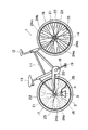
図1ないし図4は本発明の一実施の形態(実施の形態1)を示すもので、図1は本発明のタイヤの自動空気入れ装置を自転車の車輪に取り付けた状態の全体構成の概要を示す側面図、図2は同上空気入れ装置を取付けた車輪の部分を拡大して示す側面図、図3は図2のA−A線で切断し、一部を拡大して示す説明図、図4は作用説明図である。 1 to 4 show an embodiment (Embodiment 1) of the present invention, and FIG. 1 shows an outline of the overall configuration in a state in which the tire automatic inflating device of the present invention is attached to a bicycle wheel. FIG. 2 is an enlarged side view showing a portion of the wheel to which the above-described air purifier is attached. FIG. 3 is an explanatory view showing an enlarged portion cut along the line AA in FIG. 4 is an operation explanatory diagram.
まづ、図示の自転車の構成等の概要について説明する。上記図1〜図4において、自転車1はフレーム11と、ハンドル12と、サドル13と、前後の車軸14,15と、前車輪16及び後車輪17と、クランク18と、ペダル19、及びチェーン20等を備える。
前記後車輪17は、円形状のリム21と、このリム21に篏装したタイヤ22と、リム21の中心に配置し、車軸15に回転自在に軸装されたハブ23と、このハブ23の両端側とリム21とを連結する複数本の直線状のスポーク24a,24bと、リム21に取付けたタイヤの空気バルブ25等を備えている。
First, an outline of the configuration of the illustrated bicycle will be described. 1 to 4, the bicycle 1 includes a frame 11, a
The
前記ハブ23は、車軸15に回転自在に篏装する中空筒部26と、この筒部26の両端部側に設けたフランジ部27a,27bとを備えている。前記スポーク24aと24bは一本置きに配置され、スポーク24aは、一端を前記リム21に取付けると共に他端をフランジ部27aに取付け、また、スポーク24bは、一端を前記リム21に取付けると共に他端をフランジ部27bに取付けて配設されている。これにより、スポーク24aと24bとの間にはスペース28が形成される(図3参照)。
The
前記前車輪16は、後車輪17と同様の構成を備えてなっているので、同一構成部分には同一符号を付して説明を省略する。
Since the
図示の自転車1は上記のように構成され、ペダルを踏んでクランク18を回転することにより、チェーン20を介して後車輪17を回転し、走行するものである。この自転車1の構成は公知の自転車と同様である。
なお、自転車1は一例として、その概要を開示したもので、図示以外の任意の型式や構成等の自転車を採用できること勿論である。
The illustrated bicycle 1 is configured as described above, and rotates the
It should be noted that the bicycle 1 is disclosed as an example as an outline, and it is needless to say that a bicycle of an arbitrary type or configuration other than that illustrated can be adopted.
次いで本発明のタイヤの自動空気入れ装置について説明する。この実施の形態1のタイヤの自動空気入れ装置は、車輪(図示では後車輪17、但し、前車輪16についても同様)のリム21とハブ23との間に、車輪の回転に支障なく装着され、車輪と一体的に回転する空気ポンプ装置2と、この空気ポンプ装置2を駆動する駆動部3と、前記ポンプ装置2の吐出口38とタイヤの空気バルブ25とを接続するホース4とを備えている。
Next, the automatic tire filling apparatus of the present invention will be described. The automatic tire filling apparatus according to the first embodiment is mounted between the
実施の形態1の前記ポンプ装置2は、回転型空気ポンプ2Aで構成されている。前記ポンプ2Aとしては、例えば、ベーンポンプやターボ型ポンプ等の空気ポンプ、及びコンプレッサー等を採用することができる。
The
前記ポンプ2Aは前記ハブ23とリム21との間に、車輪17の回転に支障なく装着される。実施の形態1の前記ポンプ2Aはスポーク24aと24bとの間の前記スペース28に収容可能な大きさに形成されている。
前記ポンプ2Aは、ポンプの回転軸31を回転自在、かつ、車軸15と略平行に配置して車輪の適当な部位に任意の手段で固定して装着される。実施の形態1のポンプ装置2は、ポンプ2Aのハウジング32の両端側を挟むようにすると共に連結部材33を介してハウジング32に固定して対設し、ポンプ2Aを支持する支持部材34a,34bを備えている。また、両支持部材34a,34bの先端部には軸受35,35を備え、両軸受35で回転軸31の両端を回転自在に支持させてある。
そして、一方の支持部材34a又は34b(図示では34a)を一方のスポーク24a又は24b(図示では24a)に固定具36及びボルト・ナット等の止め具37により固定し、他方の支持部材(図示では34b)を他方のスポーク(図示では24b)に固定具36及びボルト・ナット等の止め具37により固定してポンプ2Aを車輪に装着するように構成してある。
The
The
Then, one
上記構成により、車輪17が回転すると、ポンプ2Aは回転軸31を車輪15と略平行状態を維持したまま、車輪と一体的に回転するようになっている。即ち、車輪17が一回転すると、ポンプ2Aは車軸15の周りを一周するようになっている。
With the above configuration, when the
前記ポンプ装置2の吐出口38は前記ホース4でタイヤの空気バルブ25と接続され、ポンプ2Aから吐出される圧縮(圧力)空気をホース4を介してタイヤ22へ注入するように構成してある。
The
実施の形態1の前記駆動部3は、前記回転軸31の両端部(図示では支持部材34a及び34bとポンプ2Aの両端との間)に、回転軸31にそれぞれ固定して対設した重錘41,41で構成されている。前記両重錘41は同一、かつ適当な重量に設定される。
これにより、車輪17が一回転すると、ポンプ2A、回転軸31、及び重錘41は車軸15の周りを一周するが、重錘41はその重量により常に下向きの姿勢を保持する(図4参照)。そのため、車輪17が一回転する毎にポンプの回転軸31は重錘41の重力作用により一回転してポンプ2Aを駆動する。ポンプ2Aが駆動すると、ポンプ2Aから吐出される圧縮(圧力)空気はホース4を介してタイヤ22へ注入される。したがって、自転車1を走行中、常にタイヤへ空気を自動的に注入する。図4において、9は回転軸31が周回する円軌道を示す。
The
As a result, when the
なお、前記重錘41の重量を加減することにより、タイヤ22への過剰圧力(空気圧)の供給を防止するように設定することができる。この点に関しては後述する実施形態においても同様である。
また、前記ポンプ2Aの吐出口38の近傍にリリーフ弁(図示せず)を設け、タイヤへの過剰圧力の供給を防止する構成を採用することもできる。
In addition, by adjusting the weight of the
In addition, a relief valve (not shown) may be provided in the vicinity of the
また、実施の形態1の前記自動空気入れ装置は、前記ポンプ2A及び重錘41等の合算重量とバランスする重量のバランサー5を備えている。このバランサー5は図2に示すように、前記ポンプ2Aや重錘41等のユニットの装着部と車軸15を挟んだ反対側に位置させて、スポーク24a,24b等に固定して装着される。
In addition, the automatic inflator of Embodiment 1 includes a balancer 5 having a weight that balances the combined weight of the
上記の場合において、前記バランサー5に代え、前記ポンプ2Aや重錘41等の他の一台のユニットを車輪17のスポーク24a,24bに前記と同様に装着する構成を採用することもできる。この構成を採用するときは、他の一台のユニットのポンプの吐出口に一端を接続したホースの他端を前記ホース4に接続するように構成する。このように構成すると、車輪17が一回転する毎に両ポンプの回転軸31が一回転し、二台のポンプを駆動するので、タイヤ22への空気の注入が倍増される。
上記したバランサー5を設ける構成及びバランサー5に代えて他の一台のポンプユニットを装着するように構成できることについては、後述する各実施の形態においても同様である。
In the above case, instead of the balancer 5, another unit such as the
The same applies to the embodiments described later, and the configuration in which the balancer 5 is provided and the balancer 5 can be replaced with another pump unit.
なお、実施の形態1では、タイヤの自動空気入れ装置を自転車1の後車輪17に装着した例を開示したが、前車輪16に前記と同様に装着して使用できること勿論である。この点に関しては、後述する各実施の形態においても同様である。
In the first embodiment, the example in which the automatic tire inflation device is mounted on the
図5ないし図7は本発明の他の実施の形態(実施の形態2)を示すもので、図5はタイヤの自動空気入れ装置を自転車の車輪に取付けた状態の要部の概要を示す正面方向から見た説明図、図6は図5のB−B線で切断し、要部の概要を示す説明図、図7は作用説明図である。実施の形態2のタイヤの自動空気入れ装置において、実施の形態1で既に説明した構成と共通する部材等には同一符号を付し、説明を省略する。 FIGS. 5 to 7 show another embodiment (Embodiment 2) of the present invention, and FIG. 5 is a front view showing an outline of a main part in a state where an automatic air purging device for a tire is attached to a wheel of a bicycle. FIG. 6 is an explanatory diagram viewed from the direction, FIG. 6 is an explanatory diagram showing an outline of the main part, cut along line BB in FIG. In the automatic tire filling apparatus of the second embodiment, the same reference numerals are given to members and the like that are the same as those already described in the first embodiment, and description thereof is omitted.
実施の形態2は空気ポンプ装置6及びポンプ装置を駆動する駆動部7の構成に特徴がある。
The second embodiment is characterized in the configuration of the
実施の形態2の空気ポンプ装置6は往復運動型空気ポンプで構成されている。往復運動型空気ポンプとしては、例えばピストンポンプ、プランジャ・ポンプ、或いはタイヤフラム・ポンプ等を採用することができる。実施の形態2ではピストンポンプ6Aを採用した例が開示されている。
The
前記ピストンポンプ6Aは適当な径及び長さのシリンダ51と、このシリンダ51内に摺動自在に収容したピストン52と、一端をピストン52固定すると共に他端をシリンダ51から突出して設けたピストンのロッド53と、シリンダ51の底部側(図5、図6において上端側)の適当部に設けた吐出口54、及びリリーフ弁55とを備えている。
前記ポンプ6Aは、ロッド53によりピストン52を底部側へ押動することにより圧縮(圧力)空気を吐出口から吐出させるように構成されている。前記ポンプ6Aは、シリンダ51内の底部側に設けられ、ピストン52をロッド53側へ付勢せしめるコイルバネ等よりなる復帰バネ56を備える。これにより、ピストン52(及びロッド53)を前記バネの作用で先端側(図5、図6において下端側)の方向へ押圧され、復帰するように構成されている。
なお、この場合において、前記ロッド53の突出端部に円形等のフランジ等を形成し、このフランジ等とシリンダ51との間に前記復帰バネ56を介装して設け、ピストン52及びロッド53を復帰させるようにした構成を採用することもできる。この構成によっても原理的には前記と同様に作用してピストン(及びロッド)を復帰させることができる。この点に関しては、後述する各実施の形態においても同様である。
The
The
In this case, a circular flange or the like is formed at the protruding end of the
前記ポンプ6Aは、前記ハブ23とリム21との間に、車輪17の回転に支障なく、かつ、車輪17と一体的に回転するように装着される。ポンプ6Aを装着する装着手段は任意の構成を採用できる。
実施の形態2では、シリンダ51の底部に固定して設けられ、前記バブ23の中空筒部26の外径と略同径の半円形状に形成した取付部材57と、前記筒部26の外径と略同径の半円形状に形成した取付部材58とを備える。前記両取付部材57,58の両側縁部には外方へ突出した鍔部59,60が形成されている。
そして、前記両取付部材57,58で中空筒部26を挟ませ、ボルト・ナット等の止め具61で両鍔部59,60を固定することにより、ポンプ6Aを中空筒部26に固定して装着するように構成してある。
The
In the second embodiment, a mounting
Then, the
また、実施の形態のポンプ6Aは、シリンダ51の両側に、シリンダ51との間に後述する回転軸に固定して設けた重錘41,41が旋回可能な間隙部62,62(図5参照)を形成し、適当部をシリンダ51に固定して対設し、ポンプ6Aを支持する支持部材63a,63bを備えている。
そして、一方の支持部材63aを前記一方のスポーク24aに固定具64及びボルト・ナット等の止め具(図示せず)により固定し、他方の支持部材63bを前記他方のスポーク24bに固定具64及びボルト・ナット等の止め具(図示せず)により固定してポンプ6Aを車輪17に装着するように構成してある。
Further, in the
Then, one
上記構成により、車輪17が回転すると、ポンプ6Aも車輪17と一体的に回転するようになっている。即ち、車輪17が一回転すると、ポンプ6Aも一回転(車軸15の周りを一周)する。
なお、前記ポンプ2Aの上記した装着手段は一例として開示したもので、上記以外の他の構成に変更できること勿論である。
With the above configuration, when the
The mounting means of the
実施の形態2の駆動部7は、回転自在、かつ、車輪17の車軸15と略平行に配置して装着される回転軸71と、この回転軸71の所定部(前記間隙部62,62に対応する部位)に固定して対設した適当な重量の重錘41,41と、回転軸71の回転運動をポンプ6Aのロッド53に伝達する運動伝達機構72とを備えている。
The driving
実施の形態2では、前記両支持部材63a,63bの先端部に軸受65,65を備え、両軸受65で回転軸71の両端を回転自在に支持する構成を採用している。これにより、回転軸71は回転自在、かつ車軸15と略平行に配置して設けられる。
In the second embodiment, a configuration is adopted in which
前記運動伝達機構72は、上述したように回転軸71の回転運動をポンプ6Aのロッド53に伝達してポンプ6Aを駆動するものである。実施の形態2の前記機構72は、上記ロッド53と対応させ、回転軸71に固定して設けた偏心輪73(エキセン)で構成されている。他の構成は実施の形態1と同様である。
As described above, the
実施の形態2は上記のように構成したもので、次に作用等につき説明する。車輪17が一回転すると、ポンプ6A、回転軸71、重錘41及び偏心輪73は車軸15の周りを一周することになるが、実施の形態1と同様に両重錘41はその重量により常に下向きの姿勢を保持する(図7参照)。そのため、車輪が一回転する毎に回転軸71及び偏心輪73は一回転し、偏心輪73によりポンプ6Aのロッド53を介してピストン52をシリンダ51の底部方向へ押動する。
ピストン52が押動されるとポンプ6Aのシリンダ51から吐出される圧縮(圧力)空気はホース4を通ってタイヤ22へ注入される。また、偏心輪73による押動が解除されるとピストン52及びロッド53はバネ56の作用で復帰する。このように、車輪を一回転する毎にピストン52を一往復(ポンプ6Aを駆動)させ、圧縮空気を吐出する。したがって、自転車1を走行中、常時タイヤへ空気を注入する。図7において、9Aは回転軸71が周回する円軌道を示す。
The second embodiment is configured as described above. Next, the operation and the like will be described. When the
When the
なお、前記ピストンポンプ6Aは、シリンダの底部側に圧力タンクを付設した方式のピストンポンプを採用してもよい。また、実施の形態2では、運動伝達機構72として偏心輪(エキセン)を採用した例を開示したが、偏心輪に代え、カム或いはクランクで構成した運動伝達機構を採用することも勿論可能である。
なお、クランクで構成した運動伝達機構を採用する場合には、シリンダに設けた前記復帰バネ56は省略することができる。
The
In addition, when the motion transmission mechanism comprised with the crank is employ | adopted, the said
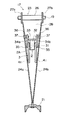
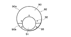
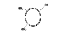
図8ないし図12は本発明の他の実施の形態(実施の形態3)を示すもので、図8はタイヤの自動空気入れ装置を自転車の車輪に取付けた状態の要部の概要を示す正面方向から見た説明図、図9は図8のC−C線で切断し、要部の概要を拡大して示す説明図、図10は押動作用体の部分を示す説明図、図11はドライメタルを示す説明図、図12は作用説明図である。実施の形態3のタイヤの自動空気入れ装置において、上述した実施の形態で既に説明した構成と共通する部材等には同一符号を付し、説明は省略する。 FIGS. 8 to 12 show another embodiment (Embodiment 3) of the present invention, and FIG. 8 is a front view showing an outline of a main part in a state where an automatic air inflation device for a tire is attached to a wheel of a bicycle. 9 is an explanatory diagram viewed from the direction, FIG. 9 is an explanatory diagram showing an enlarged outline of the main part, cut along line CC in FIG. 8, FIG. 10 is an explanatory diagram showing a portion of the body for pushing operation, FIG. FIG. 12 is an explanatory diagram showing the operation of the dry metal, and FIG. In the automatic tire filling apparatus according to the third embodiment, the same reference numerals are given to members and the like that are the same as those already described in the above-described embodiment, and description thereof is omitted.
実施の形態3は空気ポンプ装置6及びポンプ装置を駆動する駆動部8の構成及び駆動部8の配置構成等に特徴がある。
The third embodiment is characterized by the configuration of the
実施の形態3の空気ポンプ装置6は実施の形態2と同様に往復運動型空気ポンプで構成されている。往復運動型空気ポンプとしては、例えば、ピストンポンプ、プランジャ・ポンプ、或いはダイヤフラム・ポンプ等を採用することができる。実施の形態3ではピストンポンプ6Aを採用した例が開示されている。
The
前記ピストンポンプ6Aは実施の形態2の前記ポンプ6Aと同様に構成されているので、同一構成部に同一符号を付して説明は省略する。
Since the
前記ポンプ6Aは、車輪の回転に支障なく、かつ、ポンプの往復作動部(実施の形態3ではピストンのロッド53)を車軸15と略直交する方向へ向けて配置し、車輪17と一体的に回転するように、車輪17に装着される。前記ポンプ6Aを装着する装着手段は任意の構成を採用できる。
実施の形態3では、ピストン6Aのシリンダ51に固定して設け、ピストン6Aを支持する支持部材63cと、支持部材63cの基端(図8において下端)に固定して設けられ、前記ハブ23の中空筒部26の外径と略同径の半円形状に形成した取付部材57aと、前記筒部26の外径と略同径の半円形状に形成した取付部材58aとを備える。前記両取付部材57a,58aの両側縁部には外方へ突出した鍔部59a,60aが形成されている。
そして、前記両取付部材57a,58aで中空筒部26を挟ませ、ボルト・ナット等の止め具61で両鍔部59a,60aを固定することにより、ポンプ6Aを中空筒部に固定して装着するように構成してある。これにより,ポンプ6Aはロッド53を車軸15と略直交する方向へ向けて配置され、車輪17と一体的に回転するように、車輪17に装着される。
The
In the third embodiment, the
Then, the
実施の形態3の駆動部8は、車輪17のハブ23の中空筒部26に回転可能に取付ける重錘81と、この重錘81に固定して設けられ、中空筒部26に回転可能に取付ける押動作動体82とを備えている。前記重錘81はポンプ6Aの回転(車軸15の周りを周回)を許容する位置に取付ける。また、押動作動体82はポンプ6Aのロッド53と対応させて配置される。
The
実施の形態3の重錘81は、先端部(図9において上端部)を中空筒部26の外径より幾分大径の半円形状の円弧面83に形成した重錘本体84と、中空筒部26の外径より幾分大径の半円形状に形成した取付部材85とを備える。前記重錘本体84の先端部における両側縁部及び取付部材85の両側縁部には外方へ突出した鍔部86,86及び87,87が形成されている。
そして、ドライメタル88(含油メタル)を介装すると共に重錘本体84の円弧面83と取付部材85で中空筒部26を挟ませ、ボルト・ナット等の止め具89で締め付けて両鍔部を連結固定して重錘81を中空筒部26に回転可能に取付けるように構成されている。なお、前記ドライメタル88については追って説明する。
The
Then, a dry metal 88 (oil-impregnated metal) is interposed, and the hollow
前記押動作動体82は、車輪の回転に伴ってポンプ6Aのロッド53を前記作動体82の外周面と摺接させながら周回させ、ロッド53を介してピストン52を押動してポンプ6Aを駆動するものである。
実施の形態3の押動作動体82は偏心輪90(エキセン)で構成されている。偏心輪90はポンプ6Aのロッド53と対応させて配置され、中空筒部26に回転可能、かつ、重錘に固定して設けられている。前記偏心輪90は図10に最も詳細に示すように、中空筒部26の外径より幾分大径に形成すると共に中心から偏心させて設けた嵌合孔91を有している。また、偏心輪90は二つ割に分割した分割輪90a,90bで構成されている。
The push-
The push-
前記偏心輪90は上述したように重錘81に固定して設けられる。実施の形態3の偏心輪90は両分割輪90a,90bの適当部にネジ孔92,93を備えている。また、重錘本体84及び取付部材85は前記両孔92,93と対応するネジ孔(図示せず)を備えている。そして、一方の分割輪90aをネジ等94により取付部材85に固定し、他方の分割輪90bをネジ等94により重錘本体84に固定するように構成してある。この場合、上記固定手段は一例として開示したもので、溶接その他任意の手段を採用できること勿論である。
The
上記のように構成した重錘81及び偏心輪90は、偏心輪90をロッド53と対応させて配置すると共に重錘81及び偏心輪90を中空筒部26に対して回転可能に取付ける。そして、車輪17を回転することにより、ロッド53の端部を偏心輪90の外周面と摺接させながらピストンポンプ6Aを周回させるように構成してある。
The
実施の形態3の前記ドライメタル88は図11に最も詳細に示すように、二つ割に分割した一対の分割メタル88a,88bで構成されている。なお、この場合、ドライメタルに代え、ベアリング(分割ベアリング)等を採用できること勿論である。
As shown in FIG. 11 in detail, the
実施の形態3は上記のように構成したもので、次に作用等につき説明する。車輪17が一回転すると、ポンプ6Aはロッド53の端部を偏心輪90の外周面に摺接しながら車軸15の周りを一周する。一方、偏心輪90は重錘81の重力作用により車輪の回転中においても常に略同じ姿勢を維持する(図12参照)。そのため。車輪が一回転する毎にロッド53は所定の部位で一回宛押動されるので、ロッド53を介してピストン52をシリンダ51の底部方向へ押動する。
ピストン52が押動されるとポンプ6Aのシリンダ51から吐出される圧縮(圧力)空気はホース4を通ってタイヤ22へ注入される。また、ピストン52及びロッド53は復帰バネ56の作用で復帰する。このように、車輪を一回転する毎にピストン52を一往復(ポンプ6Aを駆動)させ、圧縮空気を吐出する。したがって、自転車1を走行中、常時タイヤへ空気を注入する。
The third embodiment is configured as described above. Next, the operation and the like will be described. When the
When the
なお、前記ピストンポンプ6Aは、シリンダの底部側に圧力タンクを付設した方式のピストンポンプを採用してもよい。また、実施の形態3では押動作用体82として偏心輪(エキセン)を採用した例を開示したが、偏心輪に代え、カム等で構成した押動作用体を採用することも勿論可能である。
また、上述したように、車輪の適当部にバランサーを設ける構成を採用することもできる。さらにまた、他の一台のピストンポンプを前記ポンプ6Aとによって押動作用体82を挟むようにして対向させるように配置して設ける構成を採用することもできる。
The
In addition, as described above, a configuration in which a balancer is provided at an appropriate portion of the wheel can be employed. Furthermore, it is also possible to adopt a configuration in which another piston pump is disposed and disposed so as to face each other with the
また、上述した各実施の形態では、本発明のタイヤの自動空気入れ装置を自転車の車輪に装着して使用する例を開示したが、本発明装置は電動機つき自転車、その他の任意の補助装置等を備えた自転車、或いはバイクやその他の車の車輪に装着して使用することができる。 Further, in each of the above-described embodiments, an example in which the tire automatic inflating device of the present invention is mounted on a bicycle wheel has been disclosed, but the present invention device is a bicycle with an electric motor, any other auxiliary device, etc. It can be used by attaching to the wheel of a bicycle equipped with a vehicle, a motorcycle or other vehicles.
なお、上記した各実施の形態は一例として開示したもので、本発明は上記の実施の形態に限定されるものではなく、特許請求の範囲に記載の技術思想を越脱しない範囲内において任意に変更可能なものである。 Each of the above-described embodiments is disclosed as an example, and the present invention is not limited to the above-described embodiment, and may be arbitrarily set within the scope not departing from the technical idea described in the claims. It can be changed.
2 空気ポンプ装置
3 駆動部
4 ホース
15 車軸
21 リム
23 ハブ
25 タイヤの空気バルブ
31 回転軸
38 吐出口
41 重錘
2
Claims (10)
車輪の回転に支障なく車輪に装着され、車輪と一体的に回転する空気ポンプ装置と、このポンプ装置を駆動する駆動部と、前記ポンプ装置の吐出口とタイヤの空気バルブとを接続するホースとを備え、
前記駆動部は、車輪に回転自在、かつ、車輪の車軸と略平行に配置される回転軸に固定して設けた重錘を備え、
車輪が一回転する毎に前記重錘の作用により前記回転軸を一回転させ、前記回転軸の回転運動を伝達して前記ポンプ装置を駆動するように構成したことを特徴とする、
タイヤの自動空気入れ装置。 An automatic air inflator for tires that are used on wheels,
An air pump device that is mounted on a wheel without hindrance to rotation of the wheel and rotates integrally with the wheel, a drive unit that drives the pump device, a hose that connects a discharge port of the pump device and an air valve of the tire, With
The drive unit includes a weight that is rotatably provided on a wheel and fixed to a rotary shaft that is disposed substantially parallel to the wheel axle,
The rotating shaft is rotated once by the action of the weight each time the wheel rotates once, and the pump device is driven by transmitting the rotational motion of the rotating shaft.
Tire automatic inflator.
車輪が一回転する毎に前記重錘の作用により前記回転軸を一回転させ、前記回転軸の回転運動により前記ポンプを駆動するように構成したことを特徴とする、請求項1に記載のタイヤの自動空気入れ装置。 The air pump device is composed of a rotary air pump, and the weight is fixedly provided on a rotation shaft of the pump,
2. The tire according to claim 1, wherein each time the wheel rotates once, the rotating shaft is rotated once by the action of the weight, and the pump is driven by a rotating motion of the rotating shaft. Automatic inflator.
前記駆動部は車輪に回転自在、かつ、車輪の車軸と略平行に配置して装着される回転軸と、この回転軸に固定して設けた重錘と、前記回転軸の回転運動を前記ポンプに伝達する運動伝達機構とを備え、
車輪が一回転する毎に前記重錘の作用により前記回転軸を一回転させ、前記回転軸の回転運動を前記運動伝達機構により前記ポンプに伝達させて前記ポンプを駆動するように構成したことを特徴とする、請求項1に記載のタイヤの自動空気入れ装置。 The air pump device comprises a reciprocating air pump,
The drive unit is rotatable on a wheel and is mounted so as to be disposed so as to be substantially parallel to the wheel axle, a weight fixed to the rotation shaft, and a rotational movement of the rotation shaft. A motion transmission mechanism for transmitting to
Each time the wheel rotates once, the rotary shaft is rotated once by the action of the weight, and the rotary motion of the rotary shaft is transmitted to the pump by the motion transmission mechanism to drive the pump. The tire automatic inflating device according to claim 1, characterized in that it is characterized in that:
車輪の回転に支障なく車輪に装着され、車輪と一体的に回転する往復運動型空気ポンプと、このポンプを駆動する駆動部と、前記ポンプの吐出口とタイヤの空気バルブとを接続するホースとを備え、
前記ポンプは、ポンプの往復作動部を車輪の車軸と略直交する方向へ向けて配置され、
前記駆動部は、車輪のハブの中空筒部に回転可能に取付ける重錘と、前記ポンプの往復作動部と対応させて配置され、前記中空筒部に回転可能、かつ、前記重錘に固定して設けた押動作用体とを備え、
車輪の回転に伴って前記ポンプの往復作動部を前記押動作用体の外周面と摺動させながら周回させて前記ポンプを駆動するように構成したことを特徴とする、
タイヤの自動空気入れ装置。 An automatic air inflator for tires that are used on wheels,
A reciprocating air pump that is attached to the wheel without causing any trouble in the rotation of the wheel and rotates integrally with the wheel; a drive unit that drives the pump; a hose that connects the discharge port of the pump and the air valve of the tire; With
The pump is arranged with the reciprocating operation part of the pump directed in a direction substantially orthogonal to the wheel axle,
The drive unit is disposed corresponding to a weight that is rotatably attached to a hollow cylinder part of a hub of a wheel, and a reciprocating operation part of the pump, and is rotatable to the hollow cylinder part and fixed to the weight. A pushing action body provided
It is configured to drive the pump by rotating around the wheel while rotating the reciprocating operation part of the pump while sliding with the outer peripheral surface of the pressing body.
Tire automatic inflator.
The tire automatic filling device according to any one of claims 6 to 9, further comprising a balancer attached to the wheel.
Priority Applications (1)
| Application Number | Priority Date | Filing Date | Title |
|---|---|---|---|
| JP2004046115A JP2005231573A (en) | 2004-02-23 | 2004-02-23 | Tire automatic pump device |
Applications Claiming Priority (1)
| Application Number | Priority Date | Filing Date | Title |
|---|---|---|---|
| JP2004046115A JP2005231573A (en) | 2004-02-23 | 2004-02-23 | Tire automatic pump device |
Publications (2)
| Publication Number | Publication Date |
|---|---|
| JP2005231573A true JP2005231573A (en) | 2005-09-02 |
| JP2005231573A5 JP2005231573A5 (en) | 2005-12-08 |
Family
ID=35014953
Family Applications (1)
| Application Number | Title | Priority Date | Filing Date |
|---|---|---|---|
| JP2004046115A Pending JP2005231573A (en) | 2004-02-23 | 2004-02-23 | Tire automatic pump device |
Country Status (1)
| Country | Link |
|---|---|
| JP (1) | JP2005231573A (en) |
Cited By (6)
| Publication number | Priority date | Publication date | Assignee | Title |
|---|---|---|---|---|
| WO2013037052A1 (en) * | 2011-09-15 | 2013-03-21 | Magna International Inc. | Automatic tire inflator system |
| WO2013142158A1 (en) | 2012-03-20 | 2013-09-26 | Aperia Technologies | Tire inflation system |
| US10144254B2 (en) | 2013-03-12 | 2018-12-04 | Aperia Technologies, Inc. | Tire inflation system |
| US10245908B2 (en) | 2016-09-06 | 2019-04-02 | Aperia Technologies, Inc. | System for tire inflation |
| US11453258B2 (en) | 2013-03-12 | 2022-09-27 | Aperia Technologies, Inc. | System for tire inflation |
| US11642920B2 (en) | 2018-11-27 | 2023-05-09 | Aperia Technologies, Inc. | Hub-integrated inflation system |
-
2004
- 2004-02-23 JP JP2004046115A patent/JP2005231573A/en active Pending
Cited By (12)
| Publication number | Priority date | Publication date | Assignee | Title |
|---|---|---|---|---|
| WO2013037052A1 (en) * | 2011-09-15 | 2013-03-21 | Magna International Inc. | Automatic tire inflator system |
| WO2013142158A1 (en) | 2012-03-20 | 2013-09-26 | Aperia Technologies | Tire inflation system |
| CN104254452A (en) * | 2012-03-20 | 2014-12-31 | 阿佩利亚科技公司 | Tire inflation system |
| EP2828103A4 (en) * | 2012-03-20 | 2015-11-18 | Aperia Technologies | Tire inflation system |
| US10144254B2 (en) | 2013-03-12 | 2018-12-04 | Aperia Technologies, Inc. | Tire inflation system |
| US10814684B2 (en) | 2013-03-12 | 2020-10-27 | Aperia Technologies, Inc. | Tire inflation system |
| US11453258B2 (en) | 2013-03-12 | 2022-09-27 | Aperia Technologies, Inc. | System for tire inflation |
| US11584173B2 (en) | 2013-03-12 | 2023-02-21 | Aperia Technologies, Inc. | System for tire inflation |
| US11850896B2 (en) | 2013-03-12 | 2023-12-26 | Aperia Technologies, Inc. | System for tire inflation |
| US10245908B2 (en) | 2016-09-06 | 2019-04-02 | Aperia Technologies, Inc. | System for tire inflation |
| US10814683B2 (en) | 2016-09-06 | 2020-10-27 | Aperia Technologies, Inc. | System for tire inflation |
| US11642920B2 (en) | 2018-11-27 | 2023-05-09 | Aperia Technologies, Inc. | Hub-integrated inflation system |
Similar Documents
| Publication | Publication Date | Title |
|---|---|---|
| US7311167B2 (en) | Swingable vehicle | |
| US7117910B2 (en) | Air supply device, wheel, and tire unit | |
| ES2961751T3 (en) | Vehicle wheel, in particular a bicycle wheel, hub for such wheel and vehicle fitted with such wheel | |
| KR101074866B1 (en) | Brake Apparatus for Bicycle | |
| JP2018532643A (en) | Improved wheel to recover energy, especially in electric propulsion vehicles or hybrid propulsion vehicles | |
| US20160121969A1 (en) | A hydraulic or pneumatic drive system, and a motor and a pump therefor | |
| JP2005231573A (en) | Tire automatic pump device | |
| JP3315316B2 (en) | Vehicle frame | |
| US6227810B1 (en) | Bicycle air pump structure | |
| CN110525569B (en) | Brake operating device and brake system | |
| JP2009269418A (en) | Air supply device for tire of two-wheeler | |
| JP2021142946A (en) | ABS unit | |
| US510036A (en) | Pump attachment for velocipedes | |
| US735628A (en) | Motor-bicycle. | |
| US559418A (en) | Pump attachment for bicycles | |
| CN211494351U (en) | Balance car is felt to body | |
| JP2013208975A (en) | Suspension device | |
| US1169705A (en) | Tire-pump. | |
| CN215595817U (en) | Core of air inflation pump with changeable cylinder | |
| US1265211A (en) | Tire-pump. | |
| US654017A (en) | Means for automatically inflating pneumatic tires. | |
| WO2006054736A1 (en) | Wheel-in-type rotation-assisting air pressure device | |
| JP2012047219A (en) | Power device of vehicle | |
| US1278387A (en) | Tire-charging air-pump. | |
| JP2009173046A (en) | Wheel and tire wheel assembly |
Legal Events
| Date | Code | Title | Description |
|---|---|---|---|
| A521 | Written amendment |
Free format text: JAPANESE INTERMEDIATE CODE: A523 Effective date: 20051013 |