JP2005227183A - Quality measuring instrument - Google Patents
Quality measuring instrument Download PDFInfo
- Publication number
- JP2005227183A JP2005227183A JP2004037338A JP2004037338A JP2005227183A JP 2005227183 A JP2005227183 A JP 2005227183A JP 2004037338 A JP2004037338 A JP 2004037338A JP 2004037338 A JP2004037338 A JP 2004037338A JP 2005227183 A JP2005227183 A JP 2005227183A
- Authority
- JP
- Japan
- Prior art keywords
- sample
- quality measuring
- measurement position
- excitation light
- measuring apparatus
- Prior art date
- Legal status (The legal status is an assumption and is not a legal conclusion. Google has not performed a legal analysis and makes no representation as to the accuracy of the status listed.)
- Pending
Links
Images
Abstract
Description
本発明は、食品等の品質を測定することができる品質測定装置に関する。 The present invention relates to a quality measuring apparatus capable of measuring the quality of food and the like.
従来、穀物や生鮮食品等の品質(鮮度や食味等)を評価する方法として様々な方法が提案されているが、実際の生産現場や流通現場で用いるには適当でないという問題がある。 Conventionally, various methods have been proposed as methods for evaluating the quality (freshness, taste, etc.) of grains and fresh foods, but there is a problem that they are not suitable for use in actual production sites and distribution sites.
例えば、米の鮮度を評価する方法としては、リグニン生成量や過酸化物生成量等を測定する方法、玄米中のフリーラジカルを指標にした電子スピン共鳴(所謂「ESR」)を用いる方法、及びカタラーゼ呈色法等がある。 For example, as a method for evaluating the freshness of rice, a method for measuring lignin production amount, peroxide production amount, etc., a method using electron spin resonance (so-called “ESR”) using free radicals in brown rice as an index, and There is a catalase coloring method.
しかしながら、リグニン生成量や過酸化物生成量等を測定する方法は、玄米を砕いて粉にする等の煩雑な前処理を要するため時間とコストがかかり、かつ品種間のばらつきが多いという問題がある。一方、ESRを用いた方法は感度が高く、初期酸化過程を追跡するのに適しているが、装置が高価であるため生産・流通現場における汎用装置としては使いにくいという問題がある。カタラーゼ呈色法は、高価な装置を使わず鮮度が評価できるという利点があるが、種々の薬剤を使った前処理を要するため、薬剤の取り扱いに不慣れな作業者が多い生産・流通現場で用いるには適当でなく、また測定に時間がかかるという問題点がある。 However, the method of measuring the amount of lignin produced, the amount of peroxide produced, etc. has the problem that it takes time and cost because it requires complicated pretreatment such as crushing brown rice into powder, and there are many variations between varieties. is there. On the other hand, the method using ESR has high sensitivity and is suitable for tracking the initial oxidation process. However, since the apparatus is expensive, there is a problem that it is difficult to use as a general-purpose apparatus in production / distribution sites. The catalase coloring method has the advantage that freshness can be evaluated without using expensive equipment, but it requires pretreatment with various chemicals, so it is used in production and distribution sites where many workers are unfamiliar with the handling of chemicals. There is a problem in that it is not suitable and takes a long time to measure.
そこで、上述した如き問題点を解消するための方法として、食品の蛍光画像から食品の鮮度を測定する方法(所謂「紫外線励起蛍光画像法」)が提案されている(例えば、非特許文献1参照)。 Therefore, as a method for solving the above-described problems, a method of measuring the freshness of food from a fluorescent image of food (so-called “ultraviolet-excited fluorescence imaging”) has been proposed (for example, see Non-Patent Document 1). ).
この紫外線励起蛍光画像法は、食品の蛍光画像から得られる蛍光強度と食品の鮮度との間に相関関係があることに着目して成されたものであり、特定範囲の波長の紫外線を食品に照射すると共に、当該紫外線の照射により食品が発する蛍光の画像を撮像し、その蛍光画像から得られる蛍光強度を指標として食品の鮮度を評価するものである。この紫外線励起蛍光画像法によれば、食品に対して上述した如き煩雑な前処理を施さずに食品の鮮度を測定することができるので、食品の鮮度を極めて容易かつ迅速に評価することができる。 This ultraviolet-excited fluorescence imaging method was made by paying attention to the fact that there is a correlation between the fluorescence intensity obtained from a fluorescent image of food and the freshness of the food. In addition to irradiating, an image of the fluorescence emitted by the food by the irradiation of the ultraviolet rays is taken, and the freshness of the food is evaluated using the fluorescence intensity obtained from the fluorescence image as an index. According to this ultraviolet-excited fluorescence imaging method, the freshness of the food can be measured without subjecting the food to the complicated pretreatment as described above, so the freshness of the food can be evaluated very easily and quickly. .
しかしながら、この紫外線励起蛍光画像法を実際の生産・流通現場においても実施可能に具現化した装置は未だ開発されておらず、したがって、該方法の適用により簡便かつ高感度に食品の品質を測定できると共に実際の生産・流通現場にも適用可能な装置の開発が求められている。
本発明は、上記事実を考慮し、食品等の品質を容易かつ迅速に測定することができる品質測定装置を得ることを目的とする。 In view of the above facts, an object of the present invention is to obtain a quality measuring device capable of easily and quickly measuring the quality of food and the like.
上記課題を解決するために、請求項1記載の発明に係る品質測定装置は、暗箱と、前記暗箱内に設けられ、複数の試料を同時に保持可能とされると共に、保持した複数の試料のうちの任意に選択された試料を前記暗箱内に設定された所定の測定位置に移動可能な試料保持手段と、前記測定位置に位置する前記選択された試料に励起光を照射する励起光照射手段と、前記測定位置に位置する前記選択された試料を撮像する撮像手段と、を備えたことを特徴としている。 In order to solve the above-mentioned problem, a quality measuring device according to claim 1 is provided in a dark box and in the dark box, and is capable of holding a plurality of samples at the same time. A sample holding means capable of moving the arbitrarily selected sample to a predetermined measurement position set in the dark box, and an excitation light irradiation means for irradiating the selected sample located at the measurement position with excitation light. Imaging means for imaging the selected sample located at the measurement position.
請求項1記載の品質測定装置では、暗箱の内部には、試料保持手段が設けられている。この試料保持手段は、複数の試料を同時に保持することができると共に、保持した複数の試料のうちの任意に選択された試料を暗箱内に設定された所定の測定位置に移動することができる。測定位置に移動された試料には、励起光照射手段により励起光が照射され、さらに、この励起光の照射により試料が発する蛍光は、撮像手段によって撮像される。撮像された蛍光画像から得られる試料の蛍光強度と試料の品質(鮮度・食味等)との間には相関関係があるため、この蛍光強度を指標として試料の品質を測定することができる。 In the quality measuring apparatus according to the first aspect, a sample holding means is provided inside the dark box. The sample holding means can hold a plurality of samples at the same time, and can move an arbitrarily selected sample of the held samples to a predetermined measurement position set in a dark box. The sample moved to the measurement position is irradiated with excitation light by the excitation light irradiating means, and fluorescence emitted from the sample by the irradiation of the excitation light is imaged by the imaging means. Since there is a correlation between the fluorescence intensity of the sample obtained from the captured fluorescence image and the quality (freshness, taste, etc.) of the sample, the quality of the sample can be measured using this fluorescence intensity as an index.
この場合、本品質測定装置では、上述した如く試料保持手段は、保持した複数の試料のうちの任意に選択された試料を所定の測定位置に移動することができるので、例えば、互いに比較し合う各種試料を試料保持手段に保持させることで、各種試料を逐次測定位置に移動させることができる。これにより、短時間内に多数の試料を安定して簡単に測定することができる。 In this case, in the quality measuring apparatus, as described above, the sample holding unit can move an arbitrarily selected sample of the held samples to a predetermined measurement position. By holding the various samples on the sample holding means, the various samples can be sequentially moved to the measurement position. Thereby, a large number of samples can be stably and easily measured within a short time.
しかも、本品質測定装置では、上述した如く試料保持手段は、暗箱内において各種試料を同時に保持し、かつ短時間内に測定処理することができるので、例えば、励起光を照射してからの時間経過等により暗箱内の雰囲気条件(温度や湿度等)が変化した場合においても、各種試料の蛍光強度を同一条件の下で測定することができる。これにより、各種試料の品質を正確に評価することができる。 Moreover, in this quality measuring apparatus, as described above, the sample holding means can simultaneously hold various samples in the dark box and can perform measurement processing within a short time. Even when the atmospheric conditions (temperature, humidity, etc.) in the dark box change due to progress or the like, the fluorescence intensity of various samples can be measured under the same conditions. Thereby, the quality of various samples can be evaluated accurately.
このように、請求項1記載の品質測定装置では、食品等の品質を容易かつ迅速に測定することができる。 Thus, the quality measuring apparatus according to claim 1 can easily and quickly measure the quality of food and the like.
請求項2記載の品質測定装置は、請求項1記載の品質測定装置において、前記励起光照射手段は、発光ダイオードとされる、ことを特徴としている。 The quality measuring apparatus according to claim 2 is the quality measuring apparatus according to claim 1, wherein the excitation light irradiation means is a light emitting diode.
請求項2記載の品質測定装置では、励起光照射手段を発光ダイオードとしたことで、装置の小型化、光源の長寿命化、及び励起強度の安定化を図ることができる。しかも、発光ダイオードは発熱が少ないため、励起光の照射による試料の乾燥を防止することができる。 In the quality measuring apparatus according to the second aspect, since the excitation light irradiation means is a light emitting diode, it is possible to reduce the size of the apparatus, extend the life of the light source, and stabilize the excitation intensity. In addition, since the light emitting diode generates little heat, it is possible to prevent the sample from being dried by irradiation with excitation light.
請求項3記載の品質測定装置は、請求項1記載又は請求項2記載の品質測定装置において、前記励起光照射手段は、前記測定位置に対して前記撮像手段とは反対側に設けられた第1励起光源と、前記測定位置に対して前記撮像手段側に設けられた第2励起光源と、を有する、ことを特徴としている。 The quality measuring device according to claim 3 is the quality measuring device according to claim 1 or 2, wherein the excitation light irradiation means is provided on the opposite side of the imaging position with respect to the measurement position. It has 1 excitation light source and the 2nd excitation light source provided in the said imaging means side with respect to the said measurement position, It is characterized by the above-mentioned.
請求項3記載の品質測定装置では、第1励起光源及び第2励起光源を備えている。第1励起光源は、測定位置に位置する試料に対して撮像手段とは反対側から励起光を照射する。試料に照射された励起光は当該試料を透過して撮像手段に入射する。これにより、透過光による試料の蛍光画像を撮像することができる。 The quality measuring apparatus according to claim 3 includes a first excitation light source and a second excitation light source. The first excitation light source irradiates the sample located at the measurement position with excitation light from the side opposite to the imaging unit. The excitation light applied to the sample passes through the sample and enters the imaging means. Thereby, the fluorescence image of the sample by transmitted light can be taken.
一方、第2励起光源は、測定位置に位置する試料に対して撮像手段側から励起光を照射する。試料に照射された励起光は当該試料で反射されて撮像手段に入射する。これにより、反射光による試料の蛍光画像を撮像することができる。 On the other hand, the second excitation light source irradiates the sample located at the measurement position with excitation light from the imaging means side. The excitation light applied to the sample is reflected by the sample and enters the imaging means. Thereby, the fluorescence image of the sample by reflected light can be imaged.
しかも、本品質測定装置では、第1励起光源と第2励起光源とを切り替えて照射条件を変えながら使用することで、同一試料において照射条件の異なる2つのデータを略同時に得ることができる。これにより、より一層正確に試料の品質を評価することができる。 Moreover, in this quality measuring apparatus, by switching between the first excitation light source and the second excitation light source and using them while changing the irradiation conditions, it is possible to obtain two pieces of data with different irradiation conditions in the same sample almost simultaneously. Thereby, the quality of a sample can be evaluated much more accurately.
請求項4記載の品質測定装置は、請求項1乃至請求項3の何れか1項記載の品質測定装置において、前記測定位置に可視光を照射する明視野用光源を備えた、ことを特徴としている。 The quality measurement apparatus according to claim 4 is the quality measurement apparatus according to any one of claims 1 to 3, further comprising a bright field light source that emits visible light to the measurement position. Yes.
請求項4記載の品質測定装置では、試料保持手段に保持されて測定位置に位置する試料を可視光により撮像することができる。これにより、撮像された画像から試料のセット状態を確認することができると共に、試料の外観状態を測定することができる。 In the quality measuring apparatus according to the fourth aspect, the sample held by the sample holding means and positioned at the measurement position can be imaged with visible light. Thereby, the set state of the sample can be confirmed from the captured image, and the appearance state of the sample can be measured.
請求項5記載の品質測定装置は、請求項1乃至請求項4の何れか1項記載の品質測定装置において、前記試料保持手段は、支軸周りに回転可能に支持され、前記試料を載置可能でかつ光を透過可能な試料載置部が前記測定位置を通過する回転移動軌跡上に設けられた回転ステージと、前記試料載置部に載置された試料のうちの任意に選択された試料が前記測定位置に位置する状態へ前記回転ステージを駆動する駆動源と、を有する、ことを特徴としている。 The quality measuring device according to claim 5 is the quality measuring device according to any one of claims 1 to 4, wherein the sample holding means is rotatably supported around a support shaft, and the sample is placed thereon. A sample mounting unit that is capable of transmitting light and is selected arbitrarily from a rotation stage provided on a rotational movement path passing through the measurement position and a sample mounted on the sample mounting unit And a drive source for driving the rotary stage to a state where the sample is located at the measurement position.
請求項5記載の品質測定装置では、回転ステージは、支軸周りに回転可能に支持されると共に測定位置を通過する回転移動軌跡上に試料載置部を有しており、この試料載置部に複数の試料を載置することができる。さらに、この回転テーブルは、試料載置部に載置された試料のうちの任意に選択された試料が測定位置に位置する状態へ駆動源によって駆動される。これにより、複数の試料を逐次測定位置に移動させることができ、短時間内に多数の試料を安定して簡単に測定することができる。 In the quality measuring apparatus according to claim 5, the rotary stage has a sample mounting part on a rotational movement locus that is rotatably supported around the support shaft and passes through the measurement position, and the sample mounting part. A plurality of samples can be placed on the surface. Further, the rotary table is driven by a driving source to a state in which an arbitrarily selected sample among the samples placed on the sample placing unit is located at the measurement position. Accordingly, a plurality of samples can be sequentially moved to the measurement position, and a large number of samples can be stably and easily measured within a short time.
また、回転ステージの試料載置部は光を透過可能とされているので、例えば、請求項3記載の品質測定装置における第1励起光源の如く、励起光の光源が測定位置に対して撮像手段とは反対側に設けられている場合、すなわち、励起光の光源が回転ステージを介して試料とは反対側に配置されている場合においても、試料載置部を透過した励起光を試料に照射させることができる。 In addition, since the sample mounting portion of the rotary stage is capable of transmitting light, for example, as in the first excitation light source in the quality measurement apparatus according to claim 3, the excitation light source is imaging means with respect to the measurement position. Even when the excitation light source is arranged on the opposite side of the sample via the rotary stage, the sample is irradiated with the excitation light transmitted through the sample mounting portion. Can be made.
このように、請求項5記載の品質測定装置では、試料保持手段を簡単な構成とすることができ、低コスト化を図ることができる。 Thus, in the quality measuring apparatus according to the fifth aspect, the sample holding means can have a simple configuration, and the cost can be reduced.
請求項6記載の品質測定装置は、請求項5記載の品質測定装置において、前記回転ステージの試料載置部は、穀物が1粒毎に載置される単粒載置部と、穀粒群が収容されたシャーレが載置されるシャーレ載置部と、を有する、ことを特徴としている。 The quality measuring device according to claim 6 is the quality measuring device according to claim 5, wherein the sample placing portion of the rotary stage includes a single grain placing portion on which each grain is placed, and a grain group. And a petri dish mounting portion on which the petri dish in which is stored is mounted.
請求項6記載の品質測定装置では、回転ステージの試料載置部は、穀物が1粒毎に載置される単粒載置部と、穀物群が収容されたシャーレが載置されるシャーレ載置部とを有している。これにより、穀物の単粒を個々に正確に測定することができると共に、穀物の1つの群の傾向を測定することができる。 7. The quality measuring apparatus according to claim 6, wherein the sample mounting portion of the rotary stage includes a single-particle mounting portion on which each grain is placed and a petri dish on which a petri dish containing a grain group is placed. And a placement unit. Thereby, a single grain of grain can be measured accurately and individually, and the tendency of one group of grains can be measured.
請求項7記載の品質測定装置は、請求項1乃至請求項6の何れか1項記載の品質測定装置において、前記撮像手段により撮像可能な範囲内にユーロピウムで処理した絹粉末又は酸化マグネシウムから成る蛍光標準片を備えた、ことを特徴としている。 A quality measuring device according to claim 7 is the quality measuring device according to any one of claims 1 to 6, comprising silk powder or magnesium oxide treated with europium within a range imageable by the imaging means. It is characterized by having a fluorescent standard piece.
請求項7記載の品質測定装置では、撮像手段により撮像可能な範囲内にユーロピウムで処理した絹粉末又は酸化マグネシウムから成る蛍光標準片が設けられており、この蛍光標準片の蛍光強度と試料の蛍光強度とを同一条件の下で測定することができる。したがって、測定により得られた蛍光標準片の蛍光強度と試料の蛍光強度との比を指標とすることで、試料相互の品質を定量的に比較することができる。 In the quality measuring apparatus according to claim 7, a fluorescent standard piece made of silk powder or magnesium oxide treated with europium is provided within a range that can be imaged by the imaging means, and the fluorescence intensity of the fluorescent standard piece and the fluorescence of the sample Intensity can be measured under the same conditions. Therefore, the quality of the samples can be quantitatively compared by using the ratio between the fluorescence intensity of the fluorescent standard piece obtained by the measurement and the fluorescence intensity of the sample as an index.
請求項8記載の品質測定装置は、請求項1乃至請求項7の何れか1項記載の品質測定装置において、前記暗箱内を換気する換気扇を備えた、ことを特徴としている。 The quality measuring device according to claim 8 is the quality measuring device according to any one of claims 1 to 7, further comprising a ventilation fan for ventilating the inside of the dark box.
請求項8記載の品質測定装置では、換気扇により暗箱内が換気されるので、励起光の照射による暗箱内の温度上昇等を抑制することができ、試料の乾燥を抑制することができる。 In the quality measuring apparatus according to the eighth aspect, since the inside of the dark box is ventilated by the ventilation fan, the temperature rise in the dark box due to the irradiation of the excitation light can be suppressed, and the drying of the sample can be suppressed.
請求項9記載の品質測定装置は、請求項1乃至請求項8の何れか1項記載の品質測定装置において、前記暗箱の内周壁には、特定範囲の波長の励起光を吸収する無反射加工が施されている、ことを特徴としている。 The quality measuring device according to claim 9 is the quality measuring device according to any one of claims 1 to 8, wherein the inner peripheral wall of the dark box absorbs excitation light having a specific wavelength range. It is characterized by that.
請求項9記載の品質測定装置では、測定位置に照射された励起光が暗箱の内周壁により反射されて間接的に試料に照射されることを抑制できる。これにより、上記反射光の影響で試料の励起強度が不安定になることを防止でき、多数の試料の蛍光強度をより一定の条件の下で測定することができる。 In the quality measuring apparatus according to the ninth aspect, it is possible to suppress the excitation light irradiated to the measurement position from being reflected by the inner peripheral wall of the dark box and being indirectly irradiated to the sample. Thereby, it is possible to prevent the excitation intensity of the sample from becoming unstable due to the influence of the reflected light, and it is possible to measure the fluorescence intensity of a large number of samples under more constant conditions.
以上説明したように、本発明の品質測定装置によれば、食品等の品質を容易かつ迅速に測定することができる。 As described above, according to the quality measuring apparatus of the present invention, the quality of food or the like can be measured easily and quickly.
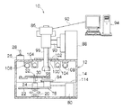
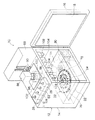
図1には、本発明の実施の形態に係る品質測定装置10の構成が概略図にて示されている。また、図2には、品質測定装置10の構成が斜視図にて示されている。
FIG. 1 is a schematic diagram showing the configuration of a
品質測定装置10は、励起光を試料に照射すると共に、当該励起光の照射により試料が発する蛍光の画像を撮像し、その蛍光画像から得られる蛍光強度を指標として試料の品質(鮮度・食味等)を測定する装置である。なお、本実施の形態では、玄米の鮮度を測定する場合に基づいて品質測定装置10の構成及び作用を説明する。
The
品質測定装置10は、試料室としての暗箱12を備えている。暗箱12は側方に開口した箱状の暗箱本体14と、暗箱本体14の前記開口部を閉塞する板状の扉16とを有している。扉16は、暗箱本体14の側壁にヒンジを介して回動可能に支持されており、横開きとされている。また、暗箱本体14の内周壁には、無反射加工としてのつや消し黒の塗装が施されており、扉16の内側面には、無反射加工としての所謂無反射シート18が貼り付けられている。これらつや消し黒の塗装及び無反射シート18は、特定範囲の波長の励起光を吸収するものである。
The
暗箱本体14の内部には、ポジショニングリフト20が設けられている。ポジショニングリフト20は、下端部が暗箱本体14の底壁に固定されており、上端部には矩形平板状の昇降台22が固定されている。このポジショニングリフト20は、図示しないモータからの駆動力により上下に伸縮するようになっており、この伸縮に対応して昇降台22が上下に移動する構成である。
A
昇降台22の上部には、駆動源としてのモータ24が配設されている。モータ24は、品質測定装置10に配設された図示しない配線を介して暗箱本体14の上部に設けられた制御部26に接続されており、制御部26に設けられたモータスイッチ28が操作されることで支軸としての回転軸30を回転させるようになっている。この回転軸30の先端(上端)には回転ステージ32が固定されている。
A
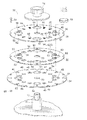
図3に示す如く、回転ステージ32は、金属材料等の平板材により形成された3枚の円盤34、36、38を備えている。
As shown in FIG. 3, the
円盤34は、その直径が例えば216ミリとされており、全面に無反射加工としてのつや消し黒の塗装が施されている。この円盤34には、径方向外側の部位に4個の円孔42が設けられている。これらの円孔42は、円盤34の周方向に沿って等間隔に(すなわち、周方向に沿って90度の間隔で)配置されている。各円孔42の直径は、無色透明なガラス材により有底円筒形に形成されたシャーレ68の外径よりも小さく設定されている。なお、このシャーレ68には、玄米の穀粒群が収容される構成である。
The
また、円盤34には、円孔42よりも小径とされた12個の円孔46が設けられている。これらの円孔46は、各円孔42の間にそれぞれ3個ずつ等間隔に配置されており、各中心が各円孔42の中心を通過する円上に配置されている。
The
さらに、円盤34の外周縁部には、各円孔42及び各円孔46に対応する位置に、それぞれ断面U字形のインデックス用切欠48が形成されている。
Further, an
一方、円盤36は、円盤34よりも小径(例えば、直径200ミリ)に設定されており、円盤34と同様に全面に無反射加工としてのつや消し黒の塗装が施されている。この円盤36には、円盤34の各円孔42に対応する位置に、それぞれ円孔50が設けられている。各円孔50の直径は、シャーレ68の外径よりも大きく設定されている。
On the other hand, the
また、円盤36には、円盤34の各円孔46に対応する位置に、それぞれ円孔52が設けられている。各円孔52の直径は、円孔46の直径よりも大きく設定されており、これらの円孔52には、それぞれ無色透明なガラス材から成る円形平板状のカバーガラス54が嵌め込まれている。
The
一方、円盤38は、円盤36と同径(すなわち、円盤34よりも小径)とされており、円盤34、36と同様に全面に無反射加工としてのつや消し黒の塗装が施されている。この円盤38には、円盤34の各円孔42及び円盤36の各円孔50に対応する位置に、それぞれ円孔56が設けられている。各円孔56の直径は、円孔50の直径と同径(すなわち、シャーレ68の外径よりも大径)とされている。
On the other hand, the
また、円盤38には、円盤34の各円孔46及び円盤36の各円孔52に対応する位置に、それぞれ穀粒の大きさ(本実施の形態では玄米の大きさ)に対応した長孔58が3個ずつ設けられている。
Further, the
さらに、円盤38には、上記3個1組とされた長孔58のうちの1組に隣接して、ユーロピウムで処理した絹粉末又は酸化マグネシウムから成る蛍光標準片60が設けられている。
Further, the
これら3枚の円盤34、36、38は、それぞれ外周縁部に設けられたネジ孔62に止めネジ64が挿入されると共に、この止めネジ64にナット66が螺合することで同軸的かつ一体的に締結されている。
The three
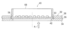
ここで、この回転ステージ32では、図4に示す如く、円盤34の円孔42、円盤36の円孔50、及び円盤38の円孔56によって1つのシャーレ載置部40が構成されており、円孔50及び円孔56の内部に挿入されたシャーレ68は、底壁の外周部が円孔42の孔縁部に係合することで回転ステージ32に載置されると共に、円孔50及び円孔56の内周壁により保持されるようになっている。
Here, in this
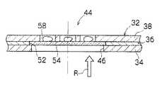
また、この回転ステージ32では、図5に示す如く、円盤34の円孔46、円盤36の円孔52、カバーガラス54、及び円盤38の3個1組とされた長孔58によって1つの単粒載置部44が構成されており、長孔58の内部に挿入された玄米の穀粒は、カバーガラス54の上面に載置されると共に、長孔58の内周壁により保持されるようになっている。
Further, in this
そして、この回転ステージ32は、円盤34、36、38の各中央部に設けられた取付孔70に、モータ24の回転軸30の先端に突設されたネジ部72が貫通され、該ネジ部72にセットネジ74が螺合することで、回転軸30に同軸的かつ一体的に固定されている。これにより、回転ステージ32は、モータ24の回転軸30と一体的に回転するようになっている。
In the
しかもこの場合、前述した各シャーレ載置部40及び各単粒載置部44は、暗箱12内に設定された所定の「測定位置」(本実施の形態では、暗箱12内の略中心部)を通過するように設定されている。
In addition, in this case, each petri
一方、モータ24の回転軸30を介して「測定位置」とは反対側における回転ステージ32の側方には、光センサ76(図2参照)が設けられている。光センサ76は図示しないステーを介して昇降台22に支持されており、図示しない検出部が回転ステージ32の円盤34の外周縁部に対向している。また、この光センサ76は、品質測定装置10に配設された図示しない配線を介して制御部26に接続されている。
On the other hand, an optical sensor 76 (see FIG. 2) is provided on the side of the
ここで、本品質測定装置10では、前述した如くモータスイッチ28が操作されることでモータ24の回転軸30が回転し、この回転軸30と一体的に回転ステージ32が回転されるが、光センサ76が円盤34の外周縁部に設けられたインデックス用切欠48を検出すると(検出部がインデックス用切欠48と対向すると)、制御部26によってモータ24への給電が遮断される。これにより、回転ステージ32は、基本的に、インデックス用切欠48が光センサ76の検出部に対向した位置で停止するようになっており、しかもこの状態では、シャーレ載置部40及び単粒載置部44のうちの何れか1つが「測定位置」に位置するようになっている。
Here, in the
すなわち、本品質測定装置10では、モータスイッチ28を1回乃至複数回操作することで、シャーレ載置部40及び単粒載置部44に載置された試料のうちの任意に選択した試料を「測定位置」へ移動させることができる構成である。
That is, in this
一方、「測定位置」に位置するシャーレ載置部40或いは単粒載置部44の真下において、昇降台22の上部には、第1励起光源としての青色発光ダイオード78(以下、青色LED78という)が設けられている。この青色LED78の発光面は、「測定位置」に位置するシャーレ載置部40或いは単粒載置部44と対向している。
On the other hand, just below the petri
また、この青色LED78は、品質測定装置10に配設された図示しない配線を介してLEDコントローラー80、及び前記制御部26に接続されており、制御部26に設けられたLEDスイッチ82(図2参照)の操作により点灯・消灯すると共に、LEDコントローラー80の操作により点灯時の輝度等を調整できるようになっている。
Further, the
さらに、青色LED78の発光面には、青色LED78から照射された光のうち特定範囲の波長の紫外線以外の光を遮蔽する紫外線透過用のバンドパスフィルター84が装着されている。
Furthermore, a band-
したがって、本品質測定装置10では、LEDスイッチ82を操作して青色LED78を点灯させることで、シャーレ載置部40或いは単粒載置部44に載置されて「測定位置」に位置する試料に対して、バンドパスフィルター84を透過した特定範囲の波長の紫外線を照射できるようになっている。具体的には、例えば、シャーレ載置部40が「測定位置」に位置する状態では、バンドパスフィルター84を透過した紫外線は、円盤34の円孔42を介してシャーレ68の底壁を透過し、シャーレ68内の試料に照射される。これに対し、単粒載置部44が「測定位置」に位置する状態では、バンドパスフィルター84を透過した紫外線は、円盤34の円孔46を介してカバーガラス54を透過し、長孔58内に収容された試料に照射される。
Therefore, in this
一方、暗箱本体14の上壁内周面には、第2励起光源としてのブラックライト104が2つ固定されている。これらのブラックライト104は、品質測定装置10に配設された図示しない配線を介して制御部26に接続されており、制御部26に設けられたブラックライトスイッチ106の操作により点灯・消灯するようになっている。各ブラックライト104を点灯させると、シャーレ載置部40或いは単粒載置部44に載置されて「測定位置」に位置する試料には紫外線が照射される構成である。
On the other hand, two
また、暗箱本体14の内部には、上記各ブラックライト104にそれぞれ隣接して明視野用光源としての蛍光灯108が設けられている。これらの蛍光灯108は、各ブラックライト104と同様に暗箱本体14の上壁内周面に固定されている。また、これらの蛍光灯108は、品質測定装置10に配設された図示しない配線を介して制御部26に接続されており、制御部26に設けられた蛍光灯スイッチ110の操作により点灯・消灯するようになっている。各蛍光灯110を点灯させると、シャーレ載置部40或いは単粒載置部44に載置されて「測定位置」に位置する試料には可視光が照射される構成である。
Further, a
一方、暗箱本体14の上方には、撮像手段としてのCCDカメラ86が設けられている。CCDカメラ86は、暗箱本体14の上部に設けられた箱状の支持部88及び該支持部88に固定されたX−Y微動装置90を介して暗箱本体14に支持されている。したがって、X−Y微動装置90を駆動することでCCDカメラ86を所定の範囲内で移動できるようになっている。
On the other hand, a
また、このCCDカメラ86には、Cマウントレンズ96が取り付けられている。Cマウントレンズ96は、図示しない赤外線カット用のIRカットフィルター、コントラスト改善用の赤色フィルター、及び拡大用のクローズアップレンズを備えており、先端(下端)にはマルチレンズフード98が取り付けられている。
In addition, a
このCマウントレンズ96は、暗箱本体14の上壁に形成された貫通孔100を貫通している。貫通孔100の直径は、前述したX−Y微動装置90によるCCDカメラ86の移動に伴うCマウントレンズ96の移動範囲よりも大きく設定されており、Cマウントレンズ96の外周部が貫通孔100の内周壁に干渉しないようになっている。
The
なお、Cマウントレンズ96の外周部には、弾性材料等から成る板状のカバー102が装着されており、Cマウントレンズ96と貫通孔100との間の隙間を閉塞している。
A plate-
このCマウントレンズ96は、その光軸が「測定位置」と交差しており、回転ステージ32のシャーレ載置部40或いは単粒載置部44に載置されて「測定位置」に位置する試料をCCDカメラ86によって撮像できるようになっている。
The C-
これにより、本品質測定装置10では、制御部26のモータスイッチ28の操作により回転ステージ32を回転させて、回転ステージ32のシャーレ載置部40に載置された試料(本実施の形態ではシャーレ68内に収容された玄米の穀粒群)、或いは単粒載置部44に載置された試料(本実施の形態では玄米の単粒)のうちの任意に選択した試料を「測定位置」へ移動させることで、当該任意に選択した試料をCCDカメラ86によって撮像することができる。なお、蛍光標準片60が隣接して設けられた単粒載置部44(長孔58)が「測定位置」へ移動された状態では、この単粒載置部44と共に蛍光標準片60を撮像できるようになっている。
Thus, in the
さらに、この場合、前述したポジショニングリフト20及びX−Y微動装置90によって昇降台22及びCCDカメラ86の位置を調整することで、前記任意に選択した試料及び蛍光標準片60に対してCマウントレンズ96の焦点を合わせることができるようになっている。
Further, in this case, by adjusting the positions of the
またさらに、CCDカメラ86には、配線92(例えば、USBケーブル等)を介してコンピュータ94が接続されている。このコンピュータ94には、画像解析用のプログラム等がインストールされており、CCDカメラ86によって撮像された画像をコンピュータ94のディスプレイに表示できると共に、表示した画像を任意に測定・解析できるようになっている。
Furthermore, a
一方、図2に示す如く、暗箱本体14の内部には、換気扇112が設けられている。換気扇112は、暗箱本体14の底壁内周面に固定されており、品質測定装置10に配設された図示しない配線を介して図示しない電源スイッチに接続されている。この換気扇112は、図示しない電源スイッチが「ON」に操作されることに対応して駆動するようになっており、暗箱本体14に設けられた図示しない空気排出口と空気取入口とを介して暗箱12内が換気される構成である。
On the other hand, as shown in FIG. 2, a ventilation fan 112 is provided inside the
また、暗箱本体14の内部は、前述した無反射シート18と同様構成の無反射シート114により上下2段に仕切られており、前述したポジショニングリフト20、昇降台22、モータ24、青色LED78、LEDコントローラー80、及び換気扇112は、当該無反射シート114により被覆されている。なお、モータ24の回転軸30は、無反射シート114に形成された貫通孔を介して無反射シート114の上側に突出している。また、青色LED78の発光面は、無反射シート114に形成された貫通孔を介して上側に露出しており、発光面に装着されたバンドパスフィルター84は無反射シート114の上側に配置されている。
The interior of the
次に、本実施の形態の作用を説明する。 Next, the operation of the present embodiment will be described.
上記構成の品質測定装置10では、回転ステージ32に試料をセットする場合には、セットネジ74を外して回転ステージ32をモータ24の回転軸30から取り外すことで、回転ステージ32を暗箱12の外に取り出すことができる。これにより、回転ステージ32に試料を容易にセットすることができる。
In the
この場合、取り外した回転ステージ32の各シャーレ載置部40には、玄米の穀粒群が収容されたシャーレ68をそれぞれ載置できると共に、各単粒載置部44には、玄米の穀粒を1粒毎に載置できる。これにより、例えば、互いに比較し合う各種玄米の試料を回転ステージ32にセットすることができる。
In this case, a
回転ステージ32に試料をセットし終えたら、セットネジ74によって回転ステージ32をモータ24の回転軸30に取り付ける。
After setting the sample on the
そして、制御部26のモータスイッチ28を操作すれば、モータ28の駆動力により回転ステージ32が回転され、光センサ76が回転ステージ32のインデックス用切欠48を検出することで、回転ステージ32が自動的に停止される。したがって、モータスイッチ28を1回乃至複数回操作することで、シャーレ載置部40及び単粒載置部44に載置された各種玄米の試料うちの任意に選択した玄米を「測定位置」へ移動させることができる。
When the
このように選択した玄米が「測定位置」に位置する状態で、青色LED78を点灯させれば、「測定位置」に位置する玄米には、バンドパスフィルター84を透過した特定範囲の波長の紫外線R(図4及び図5参照)がCCDカメラ86とは反対側から照射される。玄米に照射された紫外線Rは、当該玄米を透過してCマウントレンズ96(CCDカメラ86)に入射し、この紫外線Rの照射により玄米が発する蛍光もCマウントレンズ96(CCDカメラ86)に入射する。これにより、透過光による玄米の蛍光画像を撮像することができる。
If the
またさらに、青色LED78を消灯させて、ブラックライト104を点灯させれば、「測定位置」に位置する玄米には、CCDカメラ86側から紫外線が照射される。玄米に照射された紫外線は、当該玄米で反射されてCマウントレンズ96(CCDカメラ86)に入射し、この紫外線の照射により玄米が発する蛍光もCマウントレンズ96(CCDカメラ86)に入射する。これにより、上記透過光による玄米の蛍光画像に加えて、反射光による玄米の蛍光画像も撮像することができる。
Further, if the
撮像された玄米の蛍光画像は、コンピュータ94のディスプレイに表示されるので、コンピュータ94の画像解析用プログラム等により任意に測定・解析することができる。この場合、蛍光画像から得られる玄米の蛍光強度(輝度)と玄米の脂肪酸度との間には相関関係があり、また、玄米の脂肪酸度と玄米の古さとの間にも相関関係があるので(脂肪酸度は古米化判定の1つの指標とされるので)、例えば、画像解析用プログラム等により蛍光強度を数値化し、この数値を指標とすることで玄米の鮮度を測定することができる。
Since the captured fluorescent image of the brown rice is displayed on the display of the
さらに、本品質測定装置10では、モータスイッチ28の操作により回転ステージ10に載置された各種試料を逐次「測定位置」へ移動させることができる。これにより、短時間内に多数の試料の蛍光画像を安定して簡単に測定することができる。
Further, in the
また、本品質測定装置10では、回転ステージ32は、暗箱12内において各種玄米の試料を同時に保持し、かつ短時間内に測定処理することができるので、例えば、紫外線を照射してからの時間経過等により暗箱12内の雰囲気条件(温度や湿度等)が変化した場合においても、各種玄米の蛍光強度を同一条件の下で測定することができる。これにより、各種玄米の鮮度を正確に評価することができる。
Moreover, in this
このように、本品質測定装置10では、玄米の鮮度を容易かつ迅速に測定することができる。
As described above, the
また、本品質測定装置10では、第1励起光源を青色LED78としたことで、装置の小型化、光源の長寿命化、及び励起強度の安定化を図ることができる。しかも、この青色LED78は、透過光による測定用であるため「測定位置」に位置する試料に対して近接して配置されるが、青色LED78は発熱が少ないので、紫外線の照射による試料の乾燥を防止することができる。
Moreover, in this
さらに、本品質測定装置10では、蛍光灯108を点灯させれば、「測定位置」に位置する玄米を可視光によりCCDカメラ86で撮像することができる。撮像された画像は、コンピュータ94のディスプレイに表示されるので、表示された画像から玄米のセット状態を確認できると共に、玄米の外観状態を測定することができる。しかも、蛍光灯108により暗箱12内部を照らすことができるので、試料セット時における回転ステージ32の取り付け・取り外し作業が容易である。
Further, in the
またさらに、本品質測定装置10では、上述した如く青色LED78、ブラックライト104、及び蛍光灯108を切り替えて照射条件を変えながら使用することで、同一の玄米の試料において照射条件の異なる複数のデータを略同時に得ることができる。
Furthermore, in the
また、本品質測定装置10では、試料保持手段を回転ステージ32としたことで、試料保持手段の構成を簡素化することができ、低コスト化を図ることができる。
Moreover, in this
さらに、回転ステージ32には、玄米が1粒毎に載置される単粒載置部44と、玄米の穀粒群が収容されたシャーレ68が載置されるシャーレ載置部68とが設けられているので、玄米の単粒を個々に正確に測定することができると共に、玄米の1つの群の傾向を測定することができる。
Further, the
またさらに、回転ステージ32には、「測定位置」へ移動可能な位置にユーロピウムで処理した絹粉末又は酸化マグネシウムから成る蛍光標準片60が設けられており、この蛍光標準片60の蛍光強度と試料の蛍光強度とを同一条件の下で測定することができる。したがって、測定により得られた蛍光標準片60の蛍光強度と試料の蛍光強度との比を指標とすることで、試料相互の品質を定量的に比較することができる。
Furthermore, the
また、本品質測定装置10では、暗箱12内を換気する換気扇112を備えているので、紫外線の照射による暗箱12内の温度上昇等を抑制することができ、試料の乾燥を抑制することができる。
Further, since the
また、本品質測定装置10では、暗箱本体14の内周壁及び回転ステージ32には、無反射加工としてのつや消し黒の塗装が施され、回転ステージ32の下側に設けられた各種機器及び扉16の内側面は、無反射加工としての無反射シート18、114により被覆されている。これにより、「測定位置」に照射された紫外線が暗箱12の内周壁等により反射されて間接的に試料に照射されることを抑制できる。これにより、上記反射光の影響で試料の励起強度が不安定になることを防止でき、多数の試料をより一定の条件の下で測定することができる。
In the
以上説明した如く、本品質測定装置10では、玄米の鮮度を容易かつ迅速に測定することができる。
As described above, the
なお、上記実施の形態では、玄米の鮮度、脂肪酸度、及び蛍光強度との間の相関関係に基づき、測定により得られた玄米の蛍光強度を指標として玄米の鮮度を測定する場合について説明したが、本品質測定装置10では、鮮度に限らず、例えば、仮に玄米の食味と蛋白質含量との間に相関関係があり、また、玄米の蛋白質含量と蛍光強度との間に相関関係があれば、測定により得られた玄米の蛍光強度を指標として玄米の食味を測定することができる。
In the above embodiment, the case where the freshness of brown rice is measured using the fluorescence intensity of brown rice obtained by the measurement as an index based on the correlation between the freshness, fatty acid degree, and fluorescence intensity of brown rice has been described. In the
また、上記実施の形態では、回転ステージ32には、4個のシャーレ載置部40と12個の単粒載置部44を設定し、各単粒載置部44には玄米の穀粒に対応する長孔を3個ずつ設定したが、これに限らず、シャーレ載置部40や単粒載置部44の数・大きさ・形状等は、本品質測定装置10を使用する現場の状況や試料の大きさ等に応じて適宜設定変更することが好ましい。
Moreover, in the said embodiment, the 4 petri
さらに、上記実施の形態では、試料保持手段として回転式の回転ステージ32を適用し、モータ24の駆動力により回転ステージ32を回転させることで回転ステージ32上の試料を任意に「測定位置」へ移動可能な構成としたが、これに限らず、試料保持手段としては、例えば、試料が載置される載置台を暗箱12内の前後左右に直線的に移動させることで載置台上の試料を任意に「測定位置」へ移動可能な構成としてもよい。この場合、駆動源としては、例えば、所謂X−Yテーブルを適用することができる。
Furthermore, in the above embodiment, the
またさらに、上記実施の形態では、励起光照射手段として青色LED78及びブラックライト104を適用したが、これに限らず、励起光照射手段としては、紫外線ランプ、レーザー光源、EL、水銀ランプ、或いは蛍光ケミカルランプ等の他の光源を適用してもよい。この場合、特に紫外線を照射する光源が好ましい。
Furthermore, in the above embodiment, the
また、上記実施の形態では、品質測定装置10は、第1励起光源としての青色LED78、第2励起光源としてのブラックライト104、及び明視野用光源としての蛍光灯108を備える構成としたが、これに限らず、例えば、試料が米等の場合には、第1励起光源のみを備える構成としてもよい。
In the above embodiment, the
さらに、上記実施の形態では、回転ステージ32の円盤34の表面に蛍光標準片60を設ける構成としたが、これに限らず、蛍光標準片60は、CCDカメラ86により撮像可能な範囲内に配置されていればよく、例えば、蛍光標準片60を暗箱本体14の内周壁又は無反射シート114の上面等に配設してもよい。
Furthermore, in the above-described embodiment, the fluorescent
またさらに、上記実施の形態では、CCDカメラ86により撮像された試料の画像をコンピュータ94のディスプレイに表示すると共に、表示された画像を画像解析用のプログラム等により測定・解析する構成としたが、これに限らず、例えば、撮像された画像から得られた品質データが直接プリントアウトされる構成としてもよいし、試料の品質が一定基準以下の場合には、ランプやブザー等による警告により判別できる構成としてもよい。
In the above embodiment, the sample image captured by the
また、上記実施の形態では、玄米の鮮度を測定する場合に基づいて品質測定装置10を説明したが、これに限らず、本品質測定装置10は、肉加工製品や野菜等の生鮮食品及び大豆や小麦粉等の穀物を含む食品全般の品質を測定することができる。この場合、試料の形状に合わせて回転ステージの試料載置部の形状・数等を適宜設定変更すればよい。
Moreover, in the said embodiment, although the
10 品質測定装置
12 暗箱
18 無反射シート
24 モータ(駆動源、試料保持手段)
32 回転ステージ(試料保持手段)
40 シャーレ載置部(試料載置部)
44 単粒載置部(試料載置部)
60 蛍光標準片
78 青色発光ダイオード(第1励起光源、励起光照射手段)
86 CCDカメラ(撮像手段)
104 ブラックライト(第2励起光源、励起光照射手段)
108 蛍光灯(明視野用光源)
112 換気扇
114 無反射シート
10 Quality measuring device
12 Dark box
18 Non-reflective sheet
24 Motor (drive source, sample holding means)
32 Rotating stage (sample holding means)
40 Petri dish placement part (sample placement part)
44 Single grain placement part (sample placement part)
60 fluorescent standard strip
78 Blue light emitting diode (first excitation light source, excitation light irradiation means)
86 CCD camera (imaging means)
104 Black light (second excitation light source, excitation light irradiation means)
108 Fluorescent lamp (light source for bright field)
112 Ventilation fan
114 Non-reflective sheet
Claims (9)
前記暗箱内に設けられ、複数の試料を同時に保持可能とされると共に、保持した複数の試料のうちの任意に選択された試料を前記暗箱内に設定された所定の測定位置に移動可能な試料保持手段と、
前記測定位置に位置する前記選択された試料に励起光を照射する励起光照射手段と、
前記測定位置に位置する前記選択された試料を撮像する撮像手段と、
を備えた品質測定装置。 A dark box,
A sample provided in the dark box and capable of holding a plurality of samples at the same time, and a sample arbitrarily selected from the held samples can be moved to a predetermined measurement position set in the dark box Holding means;
Excitation light irradiation means for irradiating the selected sample located at the measurement position with excitation light;
Imaging means for imaging the selected sample located at the measurement position;
Quality measuring device with
支軸周りに回転可能に支持され、前記試料を載置可能でかつ光を透過可能な試料載置部が前記測定位置を通過する回転移動軌跡上に設けられた回転ステージと、
前記試料載置部に載置された試料のうちの任意に選択された試料が前記測定位置に位置する状態へ前記回転ステージを駆動する駆動源と、
を有する、ことを特徴とする請求項1乃至請求項4の何れか1項記載の品質測定装置。 The sample holding means is
A rotation stage that is supported rotatably around a support shaft, and on which a sample placement unit capable of placing the sample and transmitting light is provided on a rotational movement path passing through the measurement position;
A drive source that drives the rotary stage to a state where an arbitrarily selected sample of the samples placed on the sample placement unit is located at the measurement position;
5. The quality measuring apparatus according to claim 1, wherein the quality measuring apparatus includes:
Priority Applications (1)
| Application Number | Priority Date | Filing Date | Title |
|---|---|---|---|
| JP2004037338A JP2005227183A (en) | 2004-02-13 | 2004-02-13 | Quality measuring instrument |
Applications Claiming Priority (1)
| Application Number | Priority Date | Filing Date | Title |
|---|---|---|---|
| JP2004037338A JP2005227183A (en) | 2004-02-13 | 2004-02-13 | Quality measuring instrument |
Publications (2)
| Publication Number | Publication Date |
|---|---|
| JP2005227183A true JP2005227183A (en) | 2005-08-25 |
| JP2005227183A5 JP2005227183A5 (en) | 2007-05-10 |
Family
ID=35002005
Family Applications (1)
| Application Number | Title | Priority Date | Filing Date |
|---|---|---|---|
| JP2004037338A Pending JP2005227183A (en) | 2004-02-13 | 2004-02-13 | Quality measuring instrument |
Country Status (1)
| Country | Link |
|---|---|
| JP (1) | JP2005227183A (en) |
Cited By (17)
| Publication number | Priority date | Publication date | Assignee | Title |
|---|---|---|---|---|
| JP2008281477A (en) * | 2007-05-11 | 2008-11-20 | Asahi Soft Drinks Co Ltd | Label inspecting method |
| JP2009222502A (en) * | 2008-03-14 | 2009-10-01 | Jfe Engineering Corp | Quality measuring instrument of water |
| JP4567814B1 (en) * | 2010-02-12 | 2010-10-20 | 株式会社ユニソク | Food quality measuring device |
| KR101051103B1 (en) | 2009-06-22 | 2011-07-21 | 김진호 | Color checking device and color checking method |
| KR101106633B1 (en) * | 2009-08-17 | 2012-01-20 | 전남대학교산학협력단 | Dual vision optical molecular imaging device for real time fluorescence imaging of small animal |
| JP2013027340A (en) * | 2011-07-27 | 2013-02-07 | Yanmar Co Ltd | Combine harvester |
| CN103185690A (en) * | 2013-03-27 | 2013-07-03 | 浙江大学 | Uniform irradiation method and device for spectral imaging detection of agricultural product |
| JP2013148590A (en) * | 2013-04-05 | 2013-08-01 | Hitachi High-Technologies Corp | Nucleic acid analyzer and nucleic acid analysis method |
| JP2015081859A (en) * | 2013-10-23 | 2015-04-27 | 株式会社電興社 | Biological light image acquisition system, biological light acquisition probe, and method of acquiring biological light image |
| EP2362208B1 (en) * | 2010-02-05 | 2016-03-23 | Berthold Technologies GmbH & Co. KG | Measuring device for measuring bioluminescence, chemoluminescence or fluorescence of objects, measuring system and method for observing plants |
| JP2017502280A (en) * | 2013-12-18 | 2017-01-19 | オイロイムーン メディツィニシェ ラボルディアグノスティカ アーゲー | Calibration standards for devices for image-based representation of biological materials |
| JP2018036150A (en) * | 2016-08-31 | 2018-03-08 | 国立大学法人信州大学 | Quality evaluation method, quality evaluation device and quality evaluation selection system for buckwheat |
| CN109738362A (en) * | 2019-01-31 | 2019-05-10 | 浙江工业大学 | A kind of metal shaft surface image acquisition method based on line scanning |
| CN109991134A (en) * | 2019-03-29 | 2019-07-09 | 苏州精濑光电有限公司 | A kind of dust fall detection device |
| CN112362668A (en) * | 2020-11-05 | 2021-02-12 | 益阳市产商品质量监督检验研究院 | Electrolytic capacitor appearance defect detection device and detection method |
| CN113109240A (en) * | 2021-04-08 | 2021-07-13 | 国家粮食和物资储备局标准质量中心 | Method and system for determining imperfect grains of grains implemented by computer |
| JP2022158454A (en) * | 2021-04-02 | 2022-10-17 | キリンテクノシステム株式会社 | Container inspection method and apparatus |
Citations (11)
| Publication number | Priority date | Publication date | Assignee | Title |
|---|---|---|---|---|
| JPS6244234U (en) * | 1985-09-04 | 1987-03-17 | ||
| JPH0321865A (en) * | 1989-06-20 | 1991-01-30 | Kubota Corp | Glutinous rice inspecting method |
| JPH075121A (en) * | 1993-06-15 | 1995-01-10 | Nippon Steel Corp | Surface flaw inspection method for steel material |
| JPH0736263U (en) * | 1993-12-03 | 1995-07-04 | 共同印刷株式会社 | Authenticity determination device for printed matter |
| JP2000111542A (en) * | 1998-09-30 | 2000-04-21 | Nippon Seimai Kogyokai | Comprehensive inspection and evaluation method for rice |
| JP2000292353A (en) * | 1999-04-07 | 2000-10-20 | Fuji Photo Film Co Ltd | Fluorescent image formation device |
| JP2001208745A (en) * | 2000-01-27 | 2001-08-03 | Yamagata Public Corp For The Development Of Industry | Food condition evaluating method and device therefor |
| JP2002526788A (en) * | 1998-09-30 | 2002-08-20 | トレリス バイオインファーマティック インコーポレイテッド | High throughput microscope |
| JP2002365219A (en) * | 2001-06-06 | 2002-12-18 | Takara Keiki Seisakusho:Kk | Conveyance treatment apparatus |
| JP2003042956A (en) * | 2001-07-31 | 2003-02-13 | Fuji Photo Film Co Ltd | Data read method and scanner used therefor |
| JP2003294633A (en) * | 2002-03-29 | 2003-10-15 | Otsuka Denshi Co Ltd | Apparatus for measuring fluorescence |
-
2004
- 2004-02-13 JP JP2004037338A patent/JP2005227183A/en active Pending
Patent Citations (11)
| Publication number | Priority date | Publication date | Assignee | Title |
|---|---|---|---|---|
| JPS6244234U (en) * | 1985-09-04 | 1987-03-17 | ||
| JPH0321865A (en) * | 1989-06-20 | 1991-01-30 | Kubota Corp | Glutinous rice inspecting method |
| JPH075121A (en) * | 1993-06-15 | 1995-01-10 | Nippon Steel Corp | Surface flaw inspection method for steel material |
| JPH0736263U (en) * | 1993-12-03 | 1995-07-04 | 共同印刷株式会社 | Authenticity determination device for printed matter |
| JP2000111542A (en) * | 1998-09-30 | 2000-04-21 | Nippon Seimai Kogyokai | Comprehensive inspection and evaluation method for rice |
| JP2002526788A (en) * | 1998-09-30 | 2002-08-20 | トレリス バイオインファーマティック インコーポレイテッド | High throughput microscope |
| JP2000292353A (en) * | 1999-04-07 | 2000-10-20 | Fuji Photo Film Co Ltd | Fluorescent image formation device |
| JP2001208745A (en) * | 2000-01-27 | 2001-08-03 | Yamagata Public Corp For The Development Of Industry | Food condition evaluating method and device therefor |
| JP2002365219A (en) * | 2001-06-06 | 2002-12-18 | Takara Keiki Seisakusho:Kk | Conveyance treatment apparatus |
| JP2003042956A (en) * | 2001-07-31 | 2003-02-13 | Fuji Photo Film Co Ltd | Data read method and scanner used therefor |
| JP2003294633A (en) * | 2002-03-29 | 2003-10-15 | Otsuka Denshi Co Ltd | Apparatus for measuring fluorescence |
Cited By (19)
| Publication number | Priority date | Publication date | Assignee | Title |
|---|---|---|---|---|
| JP2008281477A (en) * | 2007-05-11 | 2008-11-20 | Asahi Soft Drinks Co Ltd | Label inspecting method |
| JP2009222502A (en) * | 2008-03-14 | 2009-10-01 | Jfe Engineering Corp | Quality measuring instrument of water |
| KR101051103B1 (en) | 2009-06-22 | 2011-07-21 | 김진호 | Color checking device and color checking method |
| KR101106633B1 (en) * | 2009-08-17 | 2012-01-20 | 전남대학교산학협력단 | Dual vision optical molecular imaging device for real time fluorescence imaging of small animal |
| EP2362208B1 (en) * | 2010-02-05 | 2016-03-23 | Berthold Technologies GmbH & Co. KG | Measuring device for measuring bioluminescence, chemoluminescence or fluorescence of objects, measuring system and method for observing plants |
| JP4567814B1 (en) * | 2010-02-12 | 2010-10-20 | 株式会社ユニソク | Food quality measuring device |
| WO2011099137A1 (en) * | 2010-02-12 | 2011-08-18 | 株式会社ユニソク | Food quality measuring device |
| JP2013027340A (en) * | 2011-07-27 | 2013-02-07 | Yanmar Co Ltd | Combine harvester |
| CN103185690A (en) * | 2013-03-27 | 2013-07-03 | 浙江大学 | Uniform irradiation method and device for spectral imaging detection of agricultural product |
| JP2013148590A (en) * | 2013-04-05 | 2013-08-01 | Hitachi High-Technologies Corp | Nucleic acid analyzer and nucleic acid analysis method |
| JP2015081859A (en) * | 2013-10-23 | 2015-04-27 | 株式会社電興社 | Biological light image acquisition system, biological light acquisition probe, and method of acquiring biological light image |
| JP2017502280A (en) * | 2013-12-18 | 2017-01-19 | オイロイムーン メディツィニシェ ラボルディアグノスティカ アーゲー | Calibration standards for devices for image-based representation of biological materials |
| JP2018036150A (en) * | 2016-08-31 | 2018-03-08 | 国立大学法人信州大学 | Quality evaluation method, quality evaluation device and quality evaluation selection system for buckwheat |
| CN109738362A (en) * | 2019-01-31 | 2019-05-10 | 浙江工业大学 | A kind of metal shaft surface image acquisition method based on line scanning |
| CN109991134A (en) * | 2019-03-29 | 2019-07-09 | 苏州精濑光电有限公司 | A kind of dust fall detection device |
| CN112362668A (en) * | 2020-11-05 | 2021-02-12 | 益阳市产商品质量监督检验研究院 | Electrolytic capacitor appearance defect detection device and detection method |
| JP2022158454A (en) * | 2021-04-02 | 2022-10-17 | キリンテクノシステム株式会社 | Container inspection method and apparatus |
| JP7264520B2 (en) | 2021-04-02 | 2023-04-25 | キリンテクノシステム株式会社 | Container inspection method and device |
| CN113109240A (en) * | 2021-04-08 | 2021-07-13 | 国家粮食和物资储备局标准质量中心 | Method and system for determining imperfect grains of grains implemented by computer |
Similar Documents
| Publication | Publication Date | Title |
|---|---|---|
| JP2005227183A (en) | Quality measuring instrument | |
| JP6275105B2 (en) | Equipment for microbial analysis | |
| JP7048718B2 (en) | Stray light compensation method and equipment for evaluating sample characteristics | |
| US8344334B2 (en) | Apparatus and method for detection and measurement of target compounds such as a food toxin | |
| JP2019505802A (en) | Method and apparatus for sample container and sample characterization | |
| CA2823481A1 (en) | A device for evaluation of fluids using electromagnetic energy | |
| EP1197742B1 (en) | Side multiple-lamp on-line inside quality inspecting device | |
| JP2009122083A (en) | Meter using near-infrared led | |
| JP2006322841A (en) | Spectrometry and spectrophotometer | |
| CN108060068A (en) | Multichannel fluorescence detection device | |
| JP7057820B2 (en) | Specimen evaluation method and sample evaluation device using hyperspectral imaging | |
| JP2001208745A (en) | Food condition evaluating method and device therefor | |
| CA2874533A1 (en) | Sensor for early detection of problems in algae cultures and related system and method | |
| US8345228B2 (en) | Measuring device and method for determining optical characteristic variables for verifying photochemical and electrochemical degradative reactions | |
| CN114207420A (en) | Device for controlling the quality of an operation in an industrial production line, corresponding method and computer program product | |
| JP2011169867A (en) | Photometric analysis device | |
| JP2005265626A (en) | Led lighting unit for spectrum analysis | |
| JP2009025262A (en) | X-ray analyzer | |
| JPH1151854A (en) | Spectroscopic analyzer | |
| CN219978096U (en) | Multi-wavelength ultraviolet lamp simultaneous irradiation test device | |
| JP2005172614A (en) | Quality evaluation apparatus for grains | |
| JP2008523521A5 (en) | ||
| CN220367218U (en) | Biotoxicity analysis equipment | |
| JP2006023169A (en) | Weather resistance tester | |
| CN217112037U (en) | Blood coagulation analyzer and detection assembly thereof |
Legal Events
| Date | Code | Title | Description |
|---|---|---|---|
| A521 | Written amendment |
Effective date: 20070205 Free format text: JAPANESE INTERMEDIATE CODE: A523 |
|
| A621 | Written request for application examination |
Effective date: 20070205 Free format text: JAPANESE INTERMEDIATE CODE: A621 |
|
| RD03 | Notification of appointment of power of attorney |
Free format text: JAPANESE INTERMEDIATE CODE: A7423 Effective date: 20070216 |
|
| A521 | Written amendment |
Free format text: JAPANESE INTERMEDIATE CODE: A821 Effective date: 20070205 |
|
| A521 | Written amendment |
Free format text: JAPANESE INTERMEDIATE CODE: A821 Effective date: 20070216 |
|
| A977 | Report on retrieval |
Free format text: JAPANESE INTERMEDIATE CODE: A971007 Effective date: 20090128 |
|
| A131 | Notification of reasons for refusal |
Free format text: JAPANESE INTERMEDIATE CODE: A131 Effective date: 20091124 |
|
| A02 | Decision of refusal |
Free format text: JAPANESE INTERMEDIATE CODE: A02 Effective date: 20100323 |