JP2005223758A - Image processing apparatus, control method thereof, computer program, and recording medium - Google Patents
Image processing apparatus, control method thereof, computer program, and recording medium Download PDFInfo
- Publication number
- JP2005223758A JP2005223758A JP2004031400A JP2004031400A JP2005223758A JP 2005223758 A JP2005223758 A JP 2005223758A JP 2004031400 A JP2004031400 A JP 2004031400A JP 2004031400 A JP2004031400 A JP 2004031400A JP 2005223758 A JP2005223758 A JP 2005223758A
- Authority
- JP
- Japan
- Prior art keywords
- image
- date information
- date
- information
- printing
- Prior art date
- Legal status (The legal status is an assumption and is not a legal conclusion. Google has not performed a legal analysis and makes no representation as to the accuracy of the status listed.)
- Pending
Links
Images


Classifications
-
- G—PHYSICS
- G06—COMPUTING; CALCULATING OR COUNTING
- G06T—IMAGE DATA PROCESSING OR GENERATION, IN GENERAL
- G06T11/00—2D [Two Dimensional] image generation
- G06T11/60—Editing figures and text; Combining figures or text
-
- G—PHYSICS
- G06—COMPUTING; CALCULATING OR COUNTING
- G06F—ELECTRIC DIGITAL DATA PROCESSING
- G06F3/00—Input arrangements for transferring data to be processed into a form capable of being handled by the computer; Output arrangements for transferring data from processing unit to output unit, e.g. interface arrangements
- G06F3/12—Digital output to print unit, e.g. line printer, chain printer
- G06F3/1201—Dedicated interfaces to print systems
- G06F3/1202—Dedicated interfaces to print systems specifically adapted to achieve a particular effect
- G06F3/1203—Improving or facilitating administration, e.g. print management
- G06F3/1208—Improving or facilitating administration, e.g. print management resulting in improved quality of the output result, e.g. print layout, colours, workflows, print preview
-
- G—PHYSICS
- G06—COMPUTING; CALCULATING OR COUNTING
- G06F—ELECTRIC DIGITAL DATA PROCESSING
- G06F3/00—Input arrangements for transferring data to be processed into a form capable of being handled by the computer; Output arrangements for transferring data from processing unit to output unit, e.g. interface arrangements
- G06F3/12—Digital output to print unit, e.g. line printer, chain printer
- G06F3/1201—Dedicated interfaces to print systems
- G06F3/1202—Dedicated interfaces to print systems specifically adapted to achieve a particular effect
- G06F3/1211—Improving printing performance
- G06F3/1212—Improving printing performance achieving reduced delay between job submission and print start
- G06F3/1213—Improving printing performance achieving reduced delay between job submission and print start at an intermediate node or at the final node
-
- G—PHYSICS
- G06—COMPUTING; CALCULATING OR COUNTING
- G06F—ELECTRIC DIGITAL DATA PROCESSING
- G06F3/00—Input arrangements for transferring data to be processed into a form capable of being handled by the computer; Output arrangements for transferring data from processing unit to output unit, e.g. interface arrangements
- G06F3/12—Digital output to print unit, e.g. line printer, chain printer
- G06F3/1201—Dedicated interfaces to print systems
- G06F3/1202—Dedicated interfaces to print systems specifically adapted to achieve a particular effect
- G06F3/1218—Reducing or saving of used resources, e.g. avoiding waste of consumables or improving usage of hardware resources
- G06F3/122—Reducing or saving of used resources, e.g. avoiding waste of consumables or improving usage of hardware resources with regard to computing resources, e.g. memory, CPU
-
- G—PHYSICS
- G06—COMPUTING; CALCULATING OR COUNTING
- G06F—ELECTRIC DIGITAL DATA PROCESSING
- G06F3/00—Input arrangements for transferring data to be processed into a form capable of being handled by the computer; Output arrangements for transferring data from processing unit to output unit, e.g. interface arrangements
- G06F3/12—Digital output to print unit, e.g. line printer, chain printer
- G06F3/1201—Dedicated interfaces to print systems
- G06F3/1223—Dedicated interfaces to print systems specifically adapted to use a particular technique
- G06F3/1237—Print job management
- G06F3/1253—Configuration of print job parameters, e.g. using UI at the client
- G06F3/1254—Automatic configuration, e.g. by driver
-
- G—PHYSICS
- G06—COMPUTING; CALCULATING OR COUNTING
- G06F—ELECTRIC DIGITAL DATA PROCESSING
- G06F3/00—Input arrangements for transferring data to be processed into a form capable of being handled by the computer; Output arrangements for transferring data from processing unit to output unit, e.g. interface arrangements
- G06F3/12—Digital output to print unit, e.g. line printer, chain printer
- G06F3/1201—Dedicated interfaces to print systems
- G06F3/1278—Dedicated interfaces to print systems specifically adapted to adopt a particular infrastructure
- G06F3/128—Direct printing, e.g. sending document file, using memory stick, printing from a camera
-
- H—ELECTRICITY
- H04—ELECTRIC COMMUNICATION TECHNIQUE
- H04N—PICTORIAL COMMUNICATION, e.g. TELEVISION
- H04N1/00—Scanning, transmission or reproduction of documents or the like, e.g. facsimile transmission; Details thereof
- H04N1/00127—Connection or combination of a still picture apparatus with another apparatus, e.g. for storage, processing or transmission of still picture signals or of information associated with a still picture
- H04N1/00278—Connection or combination of a still picture apparatus with another apparatus, e.g. for storage, processing or transmission of still picture signals or of information associated with a still picture with a printing apparatus, e.g. a laser beam printer
-
- H—ELECTRICITY
- H04—ELECTRIC COMMUNICATION TECHNIQUE
- H04N—PICTORIAL COMMUNICATION, e.g. TELEVISION
- H04N1/00—Scanning, transmission or reproduction of documents or the like, e.g. facsimile transmission; Details thereof
- H04N1/23—Reproducing arrangements
- H04N1/2307—Circuits or arrangements for the control thereof, e.g. using a programmed control device, according to a measured quantity
- H04N1/233—Circuits or arrangements for the control thereof, e.g. using a programmed control device, according to a measured quantity according to characteristics of the data to be reproduced, e.g. number of lines
-
- H—ELECTRICITY
- H04—ELECTRIC COMMUNICATION TECHNIQUE
- H04N—PICTORIAL COMMUNICATION, e.g. TELEVISION
- H04N1/00—Scanning, transmission or reproduction of documents or the like, e.g. facsimile transmission; Details thereof
- H04N1/23—Reproducing arrangements
- H04N1/2307—Circuits or arrangements for the control thereof, e.g. using a programmed control device, according to a measured quantity
- H04N1/2376—Inhibiting or interrupting a particular operation or device
-
- H—ELECTRICITY
- H04—ELECTRIC COMMUNICATION TECHNIQUE
- H04N—PICTORIAL COMMUNICATION, e.g. TELEVISION
- H04N1/00—Scanning, transmission or reproduction of documents or the like, e.g. facsimile transmission; Details thereof
- H04N1/32—Circuits or arrangements for control or supervision between transmitter and receiver or between image input and image output device, e.g. between a still-image camera and its memory or between a still-image camera and a printer device
- H04N1/32101—Display, printing, storage or transmission of additional information, e.g. ID code, date and time or title
- H04N1/32128—Display, printing, storage or transmission of additional information, e.g. ID code, date and time or title attached to the image data, e.g. file header, transmitted message header, information on the same page or in the same computer file as the image
-
- H—ELECTRICITY
- H04—ELECTRIC COMMUNICATION TECHNIQUE
- H04N—PICTORIAL COMMUNICATION, e.g. TELEVISION
- H04N2101/00—Still video cameras
-
- H—ELECTRICITY
- H04—ELECTRIC COMMUNICATION TECHNIQUE
- H04N—PICTORIAL COMMUNICATION, e.g. TELEVISION
- H04N2201/00—Indexing scheme relating to scanning, transmission or reproduction of documents or the like, and to details thereof
- H04N2201/0077—Types of the still picture apparatus
- H04N2201/0084—Digital still camera
-
- H—ELECTRICITY
- H04—ELECTRIC COMMUNICATION TECHNIQUE
- H04N—PICTORIAL COMMUNICATION, e.g. TELEVISION
- H04N2201/00—Indexing scheme relating to scanning, transmission or reproduction of documents or the like, and to details thereof
- H04N2201/32—Circuits or arrangements for control or supervision between transmitter and receiver or between image input and image output device, e.g. between a still-image camera and its memory or between a still-image camera and a printer device
- H04N2201/3201—Display, printing, storage or transmission of additional information, e.g. ID code, date and time or title
- H04N2201/3212—Display, printing, storage or transmission of additional information, e.g. ID code, date and time or title of data relating to a job, e.g. communication, capture or filing of an image
- H04N2201/3214—Display, printing, storage or transmission of additional information, e.g. ID code, date and time or title of data relating to a job, e.g. communication, capture or filing of an image of a date
-
- H—ELECTRICITY
- H04—ELECTRIC COMMUNICATION TECHNIQUE
- H04N—PICTORIAL COMMUNICATION, e.g. TELEVISION
- H04N2201/00—Indexing scheme relating to scanning, transmission or reproduction of documents or the like, and to details thereof
- H04N2201/32—Circuits or arrangements for control or supervision between transmitter and receiver or between image input and image output device, e.g. between a still-image camera and its memory or between a still-image camera and a printer device
- H04N2201/3201—Display, printing, storage or transmission of additional information, e.g. ID code, date and time or title
- H04N2201/3212—Display, printing, storage or transmission of additional information, e.g. ID code, date and time or title of data relating to a job, e.g. communication, capture or filing of an image
- H04N2201/3215—Display, printing, storage or transmission of additional information, e.g. ID code, date and time or title of data relating to a job, e.g. communication, capture or filing of an image of a time or duration
-
- H—ELECTRICITY
- H04—ELECTRIC COMMUNICATION TECHNIQUE
- H04N—PICTORIAL COMMUNICATION, e.g. TELEVISION
- H04N2201/00—Indexing scheme relating to scanning, transmission or reproduction of documents or the like, and to details thereof
- H04N2201/32—Circuits or arrangements for control or supervision between transmitter and receiver or between image input and image output device, e.g. between a still-image camera and its memory or between a still-image camera and a printer device
- H04N2201/3201—Display, printing, storage or transmission of additional information, e.g. ID code, date and time or title
- H04N2201/3261—Display, printing, storage or transmission of additional information, e.g. ID code, date and time or title of multimedia information, e.g. a sound signal
- H04N2201/3266—Display, printing, storage or transmission of additional information, e.g. ID code, date and time or title of multimedia information, e.g. a sound signal of text or character information, e.g. text accompanying an image
-
- H—ELECTRICITY
- H04—ELECTRIC COMMUNICATION TECHNIQUE
- H04N—PICTORIAL COMMUNICATION, e.g. TELEVISION
- H04N2201/00—Indexing scheme relating to scanning, transmission or reproduction of documents or the like, and to details thereof
- H04N2201/32—Circuits or arrangements for control or supervision between transmitter and receiver or between image input and image output device, e.g. between a still-image camera and its memory or between a still-image camera and a printer device
- H04N2201/3201—Display, printing, storage or transmission of additional information, e.g. ID code, date and time or title
- H04N2201/3271—Printing or stamping
-
- H—ELECTRICITY
- H04—ELECTRIC COMMUNICATION TECHNIQUE
- H04N—PICTORIAL COMMUNICATION, e.g. TELEVISION
- H04N2201/00—Indexing scheme relating to scanning, transmission or reproduction of documents or the like, and to details thereof
- H04N2201/32—Circuits or arrangements for control or supervision between transmitter and receiver or between image input and image output device, e.g. between a still-image camera and its memory or between a still-image camera and a printer device
- H04N2201/3201—Display, printing, storage or transmission of additional information, e.g. ID code, date and time or title
- H04N2201/3273—Display
Landscapes
- Engineering & Computer Science (AREA)
- Theoretical Computer Science (AREA)
- Physics & Mathematics (AREA)
- General Engineering & Computer Science (AREA)
- General Physics & Mathematics (AREA)
- Multimedia (AREA)
- Signal Processing (AREA)
- Human Computer Interaction (AREA)
- Computer Security & Cryptography (AREA)
- Quality & Reliability (AREA)
- Mathematical Physics (AREA)
- Studio Devices (AREA)
- Television Signal Processing For Recording (AREA)
- Editing Of Facsimile Originals (AREA)
- Image Processing (AREA)
Abstract
Description
本発明は、画像をプリントする際に、画像に写し込まれた日付とプリンタ装置で付加する日付を二重にプリントしてしまうことを防止する画像処理装置に関するものである。 The present invention relates to an image processing apparatus that prevents a date printed on an image and a date added by a printer device from being printed twice when an image is printed.
従来から、デジタルカメラやデジタルビデオカメラなどの撮影機器をプリンタ装置と通信ケーブルや無線で接続したりまたは一体的に構成したりすることで、撮影機器で撮影された画像情報を、コンピュータなどの画像情報を処理する情報処理機器を介することなくプリントすることが可能である。 Conventionally, image information captured by a photographic device can be converted into an image such as a computer by connecting a photographic device such as a digital camera or digital video camera to a printer device via a communication cable or wireless, or by configuring it integrally. It is possible to print without going through an information processing device that processes information.
プリンタ装置を接続して撮影された画像情報をプリント可能なこのような撮影機器では、撮影機器からプリントする画像の選択およびペーパー設定・日付プリント設定・枚数設定といったプリント設定を行うことが可能である。また、撮影機器側において日付プリント設定をONにすることで撮影日時をプリンタ装置で付加することが可能である。 In such a photographing apparatus capable of printing image information photographed by connecting a printer device, it is possible to select an image to be printed from the photographing apparatus and perform print settings such as paper setting, date print setting, and number of sheets setting. . In addition, by setting the date print setting to ON on the photographing apparatus side, the photographing date and time can be added by the printer device.
また、撮影機器本体で撮影日時を直接画像情報として画像に写し込んで記録媒体に記録することも実施されている(特許文献1を参照。)。
しかしながら、そのようなデジタルカメラで撮影した日付写し込みのなされた画像を上記従来例のようにプリンタ装置と接続しプリントする場合、画像にはじめから画像情報として撮影日時が写し込まれているため、日付プリント設定によりプリンタ装置で撮影日時のプリント行うと、デジタルカメラ本体で画像に写し込んだ日付とプリンタ装置で付加する日付が二重にプリントされてしまう。 However, when an image with a date imprinted with such a digital camera is connected to a printer device and printed as in the above conventional example, the date and time of the image is imprinted as image information from the beginning. When the date and time of printing is printed by the printer device by the date print setting, the date imprinted on the image by the digital camera body and the date added by the printer device are printed twice.
即ち、本発明は、撮像した画像をプリントする際に、日付情報が二重にプリントされることを防止することを目的とする。 That is, an object of the present invention is to prevent date information from being printed twice when a captured image is printed.
上記課題を解決する本発明は、プリンタ装置と接続され、撮像した画像を前記プリンタ装置を制御してプリント可能な画像処理装置であって、画像を撮像する撮像手段と、前記撮像手段により撮像された画像に前記撮像が行われた日付の情報を合成するか否かの設定を受け付ける設定受付手段と、前記受け付けた設定内容に基づき、前記日付情報を前記撮像手段により撮像された画像に合成する合成手段と、前記撮像された画像に日付情報が合成されたか否かを識別するための識別情報を前記受け付けた設定に基づき生成して前記撮像された画像のヘッダに付加する識別情報生成手段と、前記識別情報が付加されたヘッダを有する画像を前記プリンタ装置へ送信する送信手段と、を備えることを特徴とする。 The present invention for solving the above-described problems is an image processing apparatus that is connected to a printer apparatus and can print a captured image by controlling the printer apparatus. The image processing apparatus captures an image, and the image capturing means captures the image. A setting accepting unit that accepts a setting as to whether or not to combine the information of the date on which the image was taken with the captured image, and the date information is synthesized with the image taken by the imaging unit based on the received setting content. Combining means; identification information generating means for generating identification information for identifying whether date information is combined with the captured image based on the received setting and adding the identification information to a header of the captured image; And transmitting means for transmitting an image having a header to which the identification information is added to the printer apparatus.
上記課題を更に解決するための本発明は、撮像した画像をプリント可能な画像処理装置であって、画像を撮像する撮像手段と、前記撮像手段により撮像された画像に前記撮像が行われた日付の情報を合成するか否かの設定を受け付ける設定受付手段と、前記受け付けた設定内容に基づき、前記日付情報を前記撮像手段により撮像された画像に合成する合成手段と、前記撮像された画像に日付情報が合成されたか否かを識別するための識別情報を前記受け付けた設定に基づき生成して前記撮像された画像のヘッダに付加する識別情報生成手段と、前記識別情報が付加されたヘッダを有する画像をプリントするプリント手段とを備えることを特徴とする。 The present invention for further solving the above problem is an image processing apparatus capable of printing a captured image, the imaging means for capturing the image, and the date when the imaging was performed on the image captured by the imaging means A setting accepting unit that accepts a setting as to whether or not to synthesize the information, a synthesizing unit that synthesizes the date information with an image captured by the imaging unit based on the received setting content, and the captured image Identification information generating means for generating identification information for identifying whether date information has been combined based on the accepted setting and adding it to the header of the captured image; and a header to which the identification information is added And a printing means for printing an image having the same.
上記課題を更に解決するための本発明は、画像を印刷可能なプリンタ装置であって、前記画像に、前記画像の撮像が行われた日付の情報が合成されているかを判定する判定手段と、前記判定手段において前記画像に前記日付情報が合成されたと判定された場合に、前記プリンタ装置における前記日付情報の前記画像への合成を抑制するように印刷条件を設定する印刷条件設定手段と、前記設定された印刷条件に基づいて印刷を行う印刷手段とを備えることを特徴とする。 The present invention for further solving the above-described problem is a printer device capable of printing an image, and a determination unit that determines whether information on a date on which the image is captured is combined with the image; A printing condition setting unit configured to set a printing condition so as to suppress combining the date information with the image in the printer device when the determination unit determines that the date information is combined with the image; Printing means for performing printing based on the set printing conditions.
本発明によれば、撮像した画像をプリントする際に、日付情報が二重にプリントされてしまうことを防止することができる。 ADVANTAGE OF THE INVENTION According to this invention, when printing the imaged image, it can prevent that date information is printed twice.
以下、本発明の実施形態を添付図面を参照しながら詳細に説明する。 Hereinafter, embodiments of the present invention will be described in detail with reference to the accompanying drawings.
図1aは、本発明の一実施形態の構成を示したブロック図である。図1aにおいて、100は画像処理装置である。10は撮影レンズ、12は絞り機能を備えるシャッター、14は光学像を電気信号に変換する撮像素子、16は撮像素子14のアナログ信号出力をディジタル信号に変換するA/D変換器である。
FIG. 1a is a block diagram showing the configuration of an embodiment of the present invention. In FIG. 1a,
18は撮像素子14、 A/D変換器16、 D/A変換器26にクロック信号や制御信号を供給するタイミング発生回路であり、メモリ制御回路22及びシステム制御回路50により制御される。
A
20は画像処理回路であり、A/D変換器16からのデータ或いはメモリ制御回路22からのデータに対して所定の画素補間処理や色変換処理を行う。さらに画像処理回路20は、日付画像の合成処理を行うことにより画像に日付を写し込むことも可能である。
An
また、画像処理回路20においては、撮像した画像データを用いて所定の演算処理を行い、得られた演算結果に基づいてシステム制御回路50が露光制御手段40、測距制御手段42に対して制御を行う、TTL(スルー・ザ・レンズ)方式のAF(オートフォーカス)処理、AE(自動露出)処理、AWB(オートホワイトバランス)処理、EF(フラッシュプリ発光)処理を行っている。
Further, the
22はメモリ制御回路であり、A/D変換器16、タイミング発生回路18、画像処理回路20、画像表示メモリ24、D/A変換器26、メモリ30、圧縮・伸長回路32を制御する。
A
A/D変換器16のデータが画像処理回路20、メモリ制御回路22を介して、或いはA/D変換器16のデータが直接メモリ制御回路22を介して、画像表示メモリ24或いはメモリ30に書き込まれる。
The data of the A /
24は画像表示メモリ、26はD/A変換器、28はTFT LCD等から成る画像表示部であり、画像表示メモリ24に書き込まれた表示用の画像データはD/A変換器26を介して画像表示部28により表示される。また、画像表示部28を用いて撮像した画像データを逐次表示すれば、電子ファインダー機能を実現することが可能である。
Reference numeral 24 denotes an image display memory, 26 denotes a D / A converter, 28 denotes an image display unit including a TFT LCD, and the image data for display written in the image display memory 24 passes through the D /
画像表示部28は、システム制御回路50の指示により任意に表示をON/OFFすることが可能であり、表示をOFFにした場合には画像処理装置100の電力消費を大幅に低減することが出来る。
The
30は撮影した静止画像や動画像を格納するためのメモリであり、所定枚数の静止画像や所定時間の動画像を格納するのに十分な記憶量を備えている。これにより、複数枚の静止画像を連続して撮影する連射撮影やパノラマ撮影の場合にも、高速かつ大量の画像書き込みをメモリ30に対して行うことが可能となる。また、メモリ30はシステム制御回路50の作業領域としても使用することが可能である。
32は適応離散コサイン変換(ADCT)等により画像データを圧縮伸長する圧縮・伸長回路であり、メモリ30に格納された画像を読み込んで圧縮処理或いは伸長処理を行い、処理を終えたデータをメモリ30に書き込む。
A compression /
40は絞り機能を備えるシャッター12を制御する露光制御手段であり、フラッシュ48と連携することによりフラッシュ調光機能も有するものである。42は撮影レンズ10のフォーカシングを制御する測距制御手段、44は撮影レンズ10のズーミングを制御するズーム制御手段、46はバリアである保護手段102の動作を制御するバリア制御手段である。
48はフラッシュであり、AF補助光の投光機能、フラッシュ調光機能も有する。露光制御手段40、測距制御手段42はTTL方式を用いて制御されており、撮像した画像データを画像処理回路20によって演算した演算結果に基づき、システム制御回路50が露光制御手段40、測距制御手段42に対して制御を行う。
A flash 48 has an AF auxiliary light projecting function and a flash light control function. The exposure control means 40 and the distance measurement control means 42 are controlled using the TTL method. Based on the calculation result obtained by calculating the captured image data by the
50は画像処理装置100全体を制御するシステム制御回路、52はシステム制御回路50の動作用の定数、変数、プログラム等を記憶するメモリである。54はシステム制御回路50でのプログラムの実行に応じて、文字、画像、音声等を用いて動作状態やメッセージ等を表示する液晶表示装置、スピーカー等の表示部であり、画像処理装置100の操作部近辺の視認し易い位置に単数或いは複数個所設置され、例えばLCDやLED、発音素子等の組み合わせにより構成されている。また、表示部54は、その一部の機能が光学ファインダー104内に設置されている。
表示部54の表示内容のうち、LCD等に表示するものとしては、単写/連写撮影表示、セルフタイマー表示、圧縮率表示、記録画素数表示、記録枚数表示、残撮影可能枚数表示、シャッタースピード表示、絞り値表示、露出補正表示、フラッシュ表示、赤目緩和表示、マクロ撮影表示、ブザー設定表示、時計用電池残量表示、電池残量表示、エラー表示、複数桁の数字による情報表示、記録媒体200及び210の着脱状態表示、通信I/F動作表示、日付け・時刻表示、等がある。また、表示部54の表示内容のうち、光学ファインダー104内に表示するものとしては、合焦表示、手振れ警告表示、フラッシュ充電表示、シャッタースピード表示、絞り値表示、露出補正表示、等がある。
Among the display contents of the
56は電気的に消去・記録可能な不揮発性メモリであり、例えばEEPROM等が用いられる。60、62、64、66、68及び70は、システム制御回路50の各種の動作指示を入力するための操作手段であり、スイッチやダイアル、タッチパネル、視線検知によるポインティング、音声認識装置等の単数或いは複数の組み合わせで構成される。
ここで、これらの操作手段の具体的な説明を行う。60はモードダイアルスイッチで、電源オフ、自動撮影モード、撮影モード、パノラマ撮影モード、再生モード、マルチ画面再生・消去モード、PC接続モード等の各機能モードを切り替え設定することが出来る。
Here, a specific description of these operating means will be given.
62はシャッタースイッチSW1で、不図示のシャッターボタンの操作途中でONとなり、AF(オートフォーカス)処理、AE(自動露出)処理、AWB(オートホワイトバランス)処理、EF(フラッシュプリ発光)処理等の動作開始を指示する。
64はシャッタースイッチSW2で、不図示のシャッターボタンの操作完了でONとなり、撮像素子12から読み出した信号をA/D変換器16、メモリ制御回路22を介してメモリ30に画像データを書き込む露光処理、画像処理回路20やメモリ制御回路22での演算を用いた現像処理および日付写し込み処理、メモリ30から画像データを読み出し、圧縮・伸長回路32で圧縮を行い、記録媒体200或いは210に画像データを書き込む記録処理という一連の処理の動作開始を指示する。
66は画像表示ON/OFFスイッチで、画像表示部28のON/OFFを設定することが出来る。この機能により、光学ファインダー104を用いて撮影を行う際に、TFT LCD等から成る画像表示部への電流供給を遮断することにより、省電力を図ることが可能となる。
Reference numeral 66 denotes an image display ON / OFF switch that can set ON / OFF of the
68は日付写し込みON/OFFスイッチで、撮影時に撮影した画像データに日付を写し込む機能を設定することができる。ここで、スイッチ68が「ON」の場合、画像データに日付を写し込む設定となり、「OFF」の場合には画像データに日付を写し込まない設定となる。 Reference numeral 68 denotes a date imprinting ON / OFF switch, which can set a function for imprinting a date on image data captured at the time of photographing. Here, when the switch 68 is “ON”, the date is set to be imprinted on the image data. When the switch 68 is “OFF”, the date is not imprinted on the image data.
70は各種ボタンやタッチパネル等からなる操作部で、メニューボタン、セットボタン、マクロボタン、マルチ画面再生改ページボタン、フラッシュ設定ボタン、単写/連写/セルフタイマー切り替えボタン、メニュー移動+(プラス)ボタン、メニュー移動−(マイナス)ボタン、再生画像移動+(プラス)ボタン、再生画像移動−(マイナス)ボタン、撮影画質選択ボタン、露出補正ボタン、日付・時間設定ボタン等がある。
80は電源制御手段で、電池検出回路、DC−DCコンバータ、通電するブロックを切り替えるスイッチ回路等により構成されており、電池の装着の有無、電池の種類、電池残量の検出を行い、検出結果及びシステム制御回路50の指示に基づいてDC−DCコンバータを制御し、必要な電圧を必要な期間、記録媒体を含む各部へ供給する。
82はコネクタ、84はコネクタ、86はアルカリ電池やリチウム電池等の一次電池やNiCd電池やNiMH電池、Li電池等の二次電池、ACアダプター等からなる電源手段である。
90及び94はメモリカードやハードディスク等の記録媒体とのインタフェース、92及び96はメモリカードやハードディスク等の記録媒体と接続を行うコネクタである。
なお、本実施形態では記録媒体を取り付けるインターフェース及びコネクタを2系統持つものとして説明している。もちろん、記録媒体を取り付けるインターフェース及びコネクタは、単数或いは複数、いずれの系統数を備える構成としても構わない。また、異なる規格のインターフェース及びコネクタを組み合わせて備える構成としても構わない。インターフェース及びコネクタとしては、PCMCIAカードやCF(コンパクトフラッシュ(登録商標))カード等の規格に準拠したものを用いて構成して構わない。 In the present embodiment, it is assumed that there are two systems of interfaces and connectors for attaching a recording medium. Of course, the interface and the connector for attaching the recording medium may have a single or a plurality of systems and any number of systems. Moreover, it is good also as a structure provided with combining the interface and connector of a different standard. The interface and connector may be configured using a PCMCIA card, a CF (Compact Flash (registered trademark)) card, or the like that conforms to a standard.
さらに、インタフェース90及び94、そしてコネクタ92及び96をPCMCIAカードやCF(コンパクトフラッシュ(登録商標))カード等の規格に準拠したものを用いて構成した場合、LANカードやモデムカード、USBカード、IEEE1394カード、P1284カード、SCSIカード、PHS等の通信カード、等の各種通信カードを接続することにより、他のコンピュータやプリンタ等の周辺機器との間で画像データや画像データに付属した管理情報を転送し合うことが出来る。
In addition, when the
98は時計で、内部電源(不図示)により動き続け、撮影時に画像のヘッダに記録される撮影日時取得等に利用される。102は、画像処理装置100のレンズ10を含む撮像部を覆う事により、撮像部の汚れや破損を防止するバリアである保護手段である。
A
104は光学ファインダであり、画像表示部28による電子ファインダー機能を使用すること無しに、光学ファインダのみを用いて撮影を行うことが可能である。また、光学ファインダー104内には、表示部54の一部の機能、例えば、合焦表示、手振れ警告表示、フラッシュ充電表示、シャッタースピード表示、絞り値表示、露出補正表示などが設置されている。
110は通信手段で、RS232CやUSB、IEEE1394、P1284、SCSI、モデム、LAN、無線通信、等の各種通信機能を有し、画像処理装置100とプリンタ装置600を専用のケーブルで接続し通信手段110により通信を行うことで、操作部70を操作し画像をプリントすることも可能である。
A
112は通信手段110により画像処理装置100をプリンタ装置600等の他の機器と接続するコネクタ或いは無線通信の場合はアンテナである。120はプリントデータ生成手段で、画像処理装置100とプリンタ装置600を接続し画像のプリントを行う際に、プリンタ装置600に送信するプリントデータを生成する。生成されたプリントデータは通信手段110によりプリンタ装置600に送信されプリントが行われる。
200はメモリカードやハードディスク等の記録媒体である。記録媒体200は、半導体メモリや磁気ディスク等から構成される記録部202、画像処理装置100とのインタフェース204、画像処理装置100と接続を行うコネクタ206を備えている。
210はメモリカードやハードディスク等の記録媒体である。記録媒体210は、半導体メモリや磁気ディスク等から構成される記録部212、画像処理装置100とのインタフェース214、画像処理装置100と接続を行うコネクタ216を備えている。
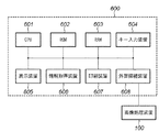
本実施形態に対応したプリント装置600は、図1b示すように、CPU601とROM602とRAM603と、キー入力装置604と表示装置605と、情報取得装置607と印刷装置608と、外部接続装置609と、から構成される。
As shown in FIG. 1B, a
上記構成において、CPU601では、ROM602に記述された各種プログラムが実行され、必要に応じてRAM603にデータを書込み、参照する処理が行われる。
In the above configuration, the
ROM602は書込み可能な不揮発性のメモリで、上記の各装置を制御するためのプログラム、データ処理を行うためのプログラムやデータが記述されている。RAM603は、ROM602に記述されたプログラムの実行に伴い、必要なデータが書込まれたり、参照されたりする。キー入力装置604では、プリント装置600において各種機能の実行を促すための実行指示入力が行われ、この指示入力にもとづき処理が実行される。
A
表示装置605では、RAM3の表示メモリに格納された表示データの表示処理を行う。実行機能の確認処理で、確認対象となる機能の機能名の表示や、印刷プレビュー表示処理で印刷プレビューの表示の他、必要な情報が表示される。情報取得装置606では、情報取得メディア(例えば、コンパクトフラッシュ(登録商標)やスマートメディアを始めとする記憶メディア)に格納される情報を読取るための装置であって、当該情報取得メディアから、画像処理装置100等で撮像された画像データを取得することができる。当該情報取得装置606は、印刷処理装置に内蔵されていても良いし、また、有線又は無線により接続されてもよい。
The
印刷装置607は、画像処理装置100から印刷実行指示がなされた場合に、装着されたカートリッジに内蔵されたインクおよび用紙を用いて、印刷処理が行われるものである。
The
外部接続装置608は、本プリンタ装置600が、画像処理装置100と無線もしくは有線により接続される場合に使用されるものであり、この外部接続装置609を介して画像処理装置100とデータのやり取りが行われる。
The
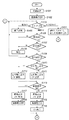
図2乃至図6を参照して、本実施形態に対応する画像処理装置100の起動・撮影動作を説明する。図2及び図3は本実施形態に対応する画像処理装置100の起動・撮影ルーチンのフローチャートを示す。
With reference to FIG. 2 thru | or FIG. 6, the starting and imaging | photography operation | movement of the
まず、電池交換等の電源投入により、システム制御回路50はフラグや制御変数等を初期化し(S101)、画像表示部28の画像表示をOFF状態に初期設定する(S102)。
First, upon power-on such as battery replacement, the
システム制御回路50は、モードダイアル60の設定位置を判断し、モードダイアル60が電源OFFに設定されていたならば(S103)、各表示部の表示を終了状態に変更し、保護手段102のバリアを閉じて撮像部を保護し、フラグや制御変数等を含む必要なパラメータや設定値、設定モードを不揮発性メモリ56に記録し、電源制御手段80により画像表示部28を含む画像処理装置100各部の不要な電源を遮断する等の所定の終了処理を行った後(S105)、S103に戻る。
The
モードダイアル60が撮影モードに設定されていたならば(S103で「撮影モード」)、S106に進む。モードダイアル60がその他のモードに設定されていたならば(S103で「その他のモード」)、システム制御回路50は選択されたモードに応じた処理を実行し(S104)、処理を終えたならばS103に戻る。
If the
システム制御回路50は、電源制御手段80により電池等により構成される電源86の残容量や動作情況が画像処理装置100の動作に問題があるか否かを判断し(S106)、問題があるならば表示部54を用いて画像や音声により所定の警告表示を行った後に(S108)、S103に戻る。
The
電源86に問題が無いならば(S106で「YES」)、システム制御回路50は記録媒体200或いは210の動作状態が画像処理装置100の動作、特に記録媒体に対する画像データの記録再生動作に問題があるか否かを判断し(S107)、問題があるならば(S107で「NO」)表示部54を用いて画像や音声により所定の警告表示を行った後に(S108)、S103に戻る。
If there is no problem with the power supply 86 (“YES” in S106), the
記録媒体200或いは210の動作状態に問題が無いならば(S107)、S109に進む。
If there is no problem in the operation state of the
日付設定がされていないならば(S109)日付写し込み不可であるので、日付写し込みフラグを解除する(S112)。日付設定がされているならば(S109)、システム制御回路50は日付写し込みON/OFFスイッチ68の設定状態を調べ(S110)、日付写し込みONに設定されていたならば日付写し込みフラグを設定し、(S111)、日付写し込みOFFに設定されていたならば日付写し込みフラグを解除する(S112)。なお、日付写し込みフラグの状態は、システム制御回路50の内部メモリ或いはメモリ52に記憶する。
If the date is not set (S109), the date imprinting flag is canceled because the date imprinting is impossible (S112). If the date is set (S109), the
ここで、日付写し込みフラグとは、S129における撮影処理において撮影した画像に日付情報を合成するか否か、及び、S134における記録処理において、画像のヘッダ部分に画像に合成された日付情報に関する情報を付加するか否かを識別するために利用される識別情報である。 Here, the date imprint flag indicates whether date information is to be combined with the image captured in the image capturing process in S129, and information regarding date information combined with the image in the header portion of the image in S134. This is identification information used for identifying whether or not to add.
続いて、システム制御回路50は、画像表示ON/OFFスイッチ66の設定状態を調べ(S113)、画像表示ONに設定されていたならば、画像表示フラグを設定すると共に(S114)、画像表示部28の画像表示をON状態に設定し(S115)、さらに撮像した画像データを逐次表示するスルー表示状態に設定して(S116)、S119に進む。
Subsequently, the
スルー表示状態においては、撮像素子12、A/D変換器16、画像処理回路20、メモリ制御回路22を介して、画像表示メモリ24に逐次書き込まれたデータを、メモリ制御回路22、D/A変換器26を介して画像表示部28により逐次表示することにより、電子ファインダー機能を実現している。
In the through display state, the data sequentially written in the image display memory 24 via the
画像表示ON/OFFスイッチ66が画像表示OFFに設定されていたならば(S113)、画像表示フラグを解除すると共に(S117)、画像表示部28の画像表示をOFF状態に設定して(S118)、S119に進む。
If the image display ON / OFF switch 66 is set to image display OFF (S113), the image display flag is canceled (S117), and the image display on the
画像表示OFFの場合は、画像表示部28による電子ファインダー機能を使用せず、光学ファインダー104を用いて撮影を行う。この場合、電力消費量の大きい画像表示部28やD/A変換器26等の消費電力を削減することが可能となる。なお、画像表示フラグの状態は、システム制御回路50の内部メモリ或いはメモリ52に記憶する。
When the image display is OFF, shooting is performed using the
シャッタースイッチSW1が押されていないならば(S119)、S103に戻る。シャッタースイッチSW1が押されたならば(S119)、システム制御回路50はシステム制御回路50の内部メモリ或いはメモリ52に記憶される画像表示フラグの状態を判断し(S120)、画像表示フラグが設定されていたならば画像表示部28の表示状態をフリーズ表示状態に設定して(S121)、S122に進む。
If the shutter switch SW1 has not been pressed (S119), the process returns to S103. If the shutter switch SW1 is pressed (S119), the
フリーズ表示状態に於いては、撮像素子12、A/D変換器16、画像処理回路20、メモリ制御回路22を介した画像表示メモリ24の画像データ書き換えを禁止し、最後に書き込まれた画像データを、メモリ制御回路22、D/A変換器26を介して画像表示部28により表示することにより、フリーズした映像を電子ファインダーに表示している。
In the freeze display state, rewriting of the image data in the image display memory 24 via the
画像表示フラグが解除されていたならば(S120)、S122に進む。システム制御回路50は、測距処理を行って撮影レンズ10の焦点を被写体に合わせ、測光処理を行って絞り値及びシャッター時間を決定する(S122)。測光処理に於いて、必要であればフラッシュの設定も行う。この測距・測光処理S122の詳細は図4を用いて後述する。
If the image display flag has been canceled (S120), the process proceeds to S122. The
測距・測光処理S122を終えたならば、システム制御回路50はシステム制御回路50の内部メモリ或いはメモリ52に記憶される画像表示フラグの状態を判断し(S123)、画像表示フラグが設定されていたならば画像表示部28の表示状態をスルー表示状態に設定して(S124)、S125に進む。なお、S124でのスルー表示状態は、S116でのスルー状態と同じ動作状態である。
After completing the distance measurement / photometry process S122, the
シャッタースイッチSW2が押されずに(S125)、さらにシャッタースイッチSW1も解除されたならば(S126)、S103に戻る。シャッタースイッチSW2が押されたならば(S125)、システム制御回路50はシステム制御回路50の内部メモリ或いはメモリ52に記憶される画像表示フラグの状態を判断し(S127)、画像表示フラグが設定されていたならば画像表示部28の表示状態を固定色表示状態に設定して(S128)、S142に進む。
If the shutter switch SW2 is not pressed (S125) and the shutter switch SW1 is also released (S126), the process returns to S103. If the shutter switch SW2 is pressed (S125), the
固定色表示状態に於いては、撮像素子12、A/D変換器16、画像処理回路20、メモリ制御回路22を介して画像表示メモリ24に書き込まれた撮影画像データの代わりに、差し替えた固定色の画像データを、メモリ制御回路22、D/A変換器26を介して画像表示部28により表示することにより、固定色の映像を電子ファインダーに表示している。
In the fixed color display state, instead of the photographed image data written in the image display memory 24 via the
画像表示フラグが解除されていたならば(S127)、S142に進む。システム制御回路50は時計98から現在の日時を取得し、システム制御回路50の内部メモリ或いはメモリ52に記憶する(S142)。ここでシステム制御回路50の内部メモリ或いはメモリ52に記憶した日時が画像の撮影日時として画像と共に記録される。
If the image display flag has been canceled (S127), the process proceeds to S142. The
システム制御回路50は、撮像素子12、A/D変換器16、、画像処理回路20、メモリ制御回路22を介して、或いはA/D変換器から直接メモリ制御回路22を介して、メモリ30に撮影した画像データを書き込む露光処理、及び、メモリ制御回路22そして必要に応じて画像処理回路20を用いて、メモリ30に書き込まれた画像データを読み出して各種処理を行う現像処理からなる撮影処理を実行する(S129)。またここで必要に応じて日付の写し込みも行う。この撮影処理S129の詳細は図5を用いて後述する。
The
システム制御回路50は、システム制御回路50の内部メモリ或いはメモリ52に記憶される画像表示フラグの状態を判断し(S130)、画像表示フラグが設定されていたならばクイックレビュー表示を行う(S133)。
The
画像表示フラグが解除されていたならば(S130)、システム制御回路50の内部メモリ或いはメモリ52に記憶されるクイックレビューフラグの状態を判断し(S131)、クイックレビューフラグが設定されていたならば、画像表示部28の画像表示をON状態に設定し(S132)、クイックレビュー表示を行う(S133)。
画像表示フラグが解除され(S130)、クイックレビューフラグも解除されていたならば(S131)、画像表示部28がOFFの状態のままS134に進む。
If the image display flag has been canceled (S130), the state of the quick review flag stored in the internal memory of the
If the image display flag is released (S130) and the quick review flag is also released (S131), the process proceeds to S134 while the
システム制御回路50は、メモリ30に書き込まれた撮影画像データを読み出して、メモリ制御回路22そして必要に応じて画像処理回路20を用いて各種画像処理を、また、圧縮・伸長回路32を用いて設定したモードに応じた画像圧縮処理を行った後、記録媒体200或いは210へ画像データの書き込みを行う記録処理を実行する(S134)。この記録処理S134の詳細は図6を用いて後述する。
The
記録処理S134が終了した際に、シャッタースイッチSW2が押された状態であったならば(S135)、システム制御回路50はシステム制御回路50の内部メモリ或いはメモリ52に記憶される連写フラグの状態を判断し(S136)、連写フラグが設定されていたならば、連続して撮影を行うためにS129に戻り、次の撮影を行う。
If the shutter switch SW2 has been pressed when the recording process S134 is completed (S135), the
連写フラグが設定されていないならば(S136)、シャッタースイッチSW2が放されるまで(S135)、現在の処理を繰り返す。 If the continuous shooting flag is not set (S136), the current process is repeated until the shutter switch SW2 is released (S135).
記録処理S134が終了した際にシャッタースイッチSW2が放された状態であった、或いは、シャッタースイッチSW2を押し続けてクイックレビュー表示を継続して撮影画像の確認を行った後にシャッタースイッチSW2を放した状態であったならば(S135)、所定のミニマムレビュー時間が経過した後にS138に進む(S137)。 The shutter switch SW2 was released when the recording process S134 was completed, or the shutter switch SW2 was released after the quick review display was confirmed by continuing to hold down the shutter switch SW2 to confirm the captured image. If it is in a state (S135), the process proceeds to S138 after a predetermined minimum review time has elapsed (S137).
なお、このミニマムレビュー時間は、固定値としても、使用者が任意に設定することが可能としても、さらには所定の範囲内で使用者が任意に設定或いは選択することが可能としても、いずれの方法で設定しても構わない。 The minimum review time can be a fixed value, can be arbitrarily set by the user, or can be arbitrarily set or selected by the user within a predetermined range. You may set by the method.
システム制御回路50は、画像表示フラグが設定されていたならば(S138)、画像表示部28の表示状態をスルー表示状態に設定して(S139)、S141に進む。
If the image display flag has been set (S138), the
画像表示フラグが解除されていたならば(S138)、画像表示部28の画像表示をOFF状態に設定して(S140)、S141に進む。
If the image display flag has been canceled (S138), the image display of the
シャッタースイッチSW1が押された状態であったならば(S141)、システム制御回路50は、S125に戻って次の撮影に備える。シャッタースイッチSW1が放された状態であったならば(S141)、システム制御回路50は、一連の撮影動作を終えてS103に戻る。
If the shutter switch SW1 has been pressed (S141), the
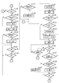
図4は、図3のS122における測距・測光処理の詳細なフローチャートを示す。システム制御回路50は、撮像素子14から電荷信号を読み出し、A/D変換器16を介して画像処理回路20に撮影画像データを逐次読み込む(S201)。この逐次読み込まれた画像データを用いて、画像処理回路20はTTL(スルー・ザ・レンズ)方式のAE(自動露出)処理、EF(フラッシュプリ発光)処理、AF(オートフォーカス)処理に用いる所定の演算を行っている。
FIG. 4 shows a detailed flowchart of the distance measurement / photometry process in S122 of FIG. The
なお、ここでの各処理は、撮影した全画素数のうちの必要に応じた特定の部分を必要個所分切り取って抽出し、演算に用いている。これにより、 TTL方式のAE、EF、AWB、AFの各処理において、中央重点モード、平均モード、評価モードの各モード等の異なるモード毎に最適な演算を行うことが可能となる。 In each processing here, a specific portion of the total number of photographed pixels is extracted by extracting a necessary portion according to necessity and used for calculation. As a result, in the TTL method AE, EF, AWB, and AF processes, it is possible to perform an optimal calculation for each different mode such as the center-weighted mode, the average mode, and the evaluation mode.
画像処理回路20での演算結果を用いて、システム制御回路50は露出(AE)が適正と判断されるまで(S202)、露光制御手段40を用いてAE制御を行う(S203)。
Using the calculation result in the
AE制御で得られた測定データを用いて、システム制御回路50はフラッシュが必要か否かを判断し(S204)、フラッシュが必要ならばフラッシュフラグをセットし、フラッシュ48を充電する(S205)。
Using the measurement data obtained by the AE control, the
露出(AE)が適正と判断したならば(S202)、測定データ及び或いは設定パラメータをシステム制御回路50の内部メモリ或いはメモリ52に記憶する。画像処理回路20での演算結果及びAE制御で得られた測定データを用いて、システム制御回路50はホワイトバランス(AWB)が適正と判断されるまで(S206)、画像処理回路20を用いて色処理のパラメータを調節してAWB制御を行う(S207)。
If it is determined that the exposure (AE) is appropriate (S202), the measurement data and / or the setting parameters are stored in the internal memory or the
ホワイトバランス(AWB)が適正と判断したならば(S206)、測定データ及び或いは設定パラメータをシステム制御回路50の内部メモリ或いはメモリ52に記憶する。AE制御及びAWB制御で得られた測定データを用いて、システム制御回路50は測距(AF)が合焦と判断されるまで(S208)、測距制御手段42を用いてAF制御を行う(S209)。
If it is determined that the white balance (AWB) is appropriate (S206), the measurement data and / or setting parameters are stored in the internal memory or the
測距(AF)が合焦と判断したならば(S208)、測定データ及び或いは設定パラメータをシステム制御回路50の内部メモリ或いはメモリ52に記憶し、測距・測光処理ルーチンS122を終了する。
If it is determined that the distance measurement (AF) is in focus (S208), the measurement data and / or setting parameters are stored in the internal memory or the
図5は、図3のS129における撮影処理の詳細なフローチャートを示す。システム制御回路50は、システム制御回路50の内部メモリ或いはメモリ52に記憶される測光データに従い、露光制御手段40によって、絞り機能を有するシャッター12を絞り値に応じて開放して撮像素子10を露光する(S301、S302)。
FIG. 5 shows a detailed flowchart of the photographing process in S129 of FIG. The
フラッシュ・フラグによりフラッシュ48が必要か否かを判断し(S303)、必要な場合はフラッシュを発光させる(S304)。システム制御回路50は、測光データに従って撮像素子12の露光終了を待ち(S305)、シャッター12を閉じて(S306)、撮像素子14から電荷信号を読み出し、A/D変換器16、画像処理回路20、メモリ制御回路22を介して、或いはA/D変換器16から直接メモリ制御回路22を介して、メモリ30に撮影画像のデータを書き込む(S307)。
It is determined whether or not the flash 48 is necessary based on the flash flag (S303), and if necessary, the flash is emitted (S304). The
設定された撮影モードに応じて、フレーム処理を行う必要があるならば(S308)、システム制御回路50は、メモリ制御回路22そして必要に応じて画像処理回路20を用いて、メモリ30に書き込まれた画像データを読み出して垂直加算処理や(S309)、色処理(S310)を順次行う。
If it is necessary to perform frame processing according to the set shooting mode (S308), the
システム制御回路50は、システム制御回路50の内部メモリ或いはメモリ52に記憶される日付写し込みフラグの状態を判断し(S311)、日付写し込みフラグが解除されていたならば、メモリ30に画像データを書き込む。
The
日付写し込みフラグが設定されていたならば(S311)、S142でシステム制御回路50の内部メモリ或いはメモリ52に記憶された撮影日時を、メモリ制御回路22、画像処理回路20を用いて画像データに合成し日付の写し込み処理を行い(S312)、処理後メモリ30に日付の写し込まれた画像データを書き込む。
If the date imprinting flag is set (S311), the shooting date and time stored in the internal memory of the
システム制御回路50は、メモリ30から画像データを読み出し、メモリ制御回路22を介して画像表示メモリ24に表示画像データの転送を行う(S313)。一連の処理を終えたならば、撮影処理ルーチンS129を終了する。
The
図6は、図3のS134における記録処理の詳細なフローチャートを示す。システム制御回路50は、メモリ制御回路22そして必要に応じて画像処理回路20を用いて、メモリ30に書き込まれた撮影画像データを読み出して撮像素子の縦横画素比率を1:1に補間する画素正方化処理を行った後(S401)、メモリ30に処理を終えた画像データを書き込む。
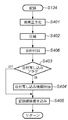
FIG. 6 shows a detailed flowchart of the recording process in S134 of FIG. The
そして、メモリ30に書き込まれた画像データを読み出して、設定したモードに応じた画像圧縮処理を圧縮・伸長回路32により行う(S402)。システム制御回路50は、S142でシステム制御回路50の内部メモリ或いはメモリ52に記憶された撮影日時を画像ヘッダに付加する(S406)。システム制御回路50は、システム制御回路50の内部メモリ或いはメモリ52に記憶される日付写し込みフラグの状態を判断し(S403)、日付写し込みフラグが解除されていたならば、S405に進む。
Then, the image data written in the
日付写し込みフラグが設定されていたならば(S403で「ON」)、画像のヘッダ部分に、画像に合成された日付情報に関する情報(日付写し込み情報)を付加する(S404)。この画像ヘッダに付加される日付写し込み情報の詳細は図7を用いて後述する。最後にインタフェース90或いは94、コネクタ92或いは96を介して、メモリカードやコンパクトフラッシュ(登録商標)カード等の記録媒体200或いは210へ圧縮した画像データの書き込みを行う(S405)。記録媒体への書き込みが終わったならば、記録処理ルーチンS134を終了する。
If the date imprinting flag has been set (“ON” in S403), information (date imprinting information) related to date information combined with the image is added to the header portion of the image (S404). Details of the date imprinting information added to the image header will be described later with reference to FIG. Finally, the compressed image data is written to the
図7aは、図6のS404において日付写し込みがなされた画像のヘッダに付加される日付写し込み情報の詳細を示す。日付写し込み情報は、画像に日付情報が合成されているか否かを識別するための情報であって、画像に日付写し込みがなされているかという情報と日付写し込みがなされている場合の画像上の日付の位置を示す情報(位置情報)からなる。画像に日付写し込みがなされているかという情報としては、日付写し込みフラグ301がある。日付写し込みフラグ301は真または偽の2値を取りうる。真であるならば画像に日付写し込みがなされていることを示す。偽であるならば画像に日付写し込みはなされていないことを示し、座標情報302乃至305の内容は意味を持たない。
FIG. 7a shows details of the date imprinting information added to the header of the image imprinted with the date imprinted in S404 of FIG. The date imprinting information is information for identifying whether date information is combined with the image, and information on whether the date imprinting is performed on the image and the date imprinting on the image. It consists of information (position information) indicating the position of the date. As information indicating whether or not the date is imprinted on the image, there is a
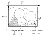
日付写し込みがなされている場合の画像上の日付の位置を示す情報としては、以下の4つがある。日付左上x座標302は日付写し込み領域306の左上コーナーの画像上でのx座標を示し、日付左上y座標303は日付写し込み領域306の左上コーナーの画像上でのy座標を示す。日付右下x座標304は日付写し込み領域306の右下コーナーの画像上でのx座標を示し、日付右下y座標305は日付写し込み領域306の右下コーナーの画像上でのy座標を示す。
Information indicating the position of the date on the image when the date is imprinted includes the following four items. The date upper left x coordinate 302 indicates the x coordinate on the upper left corner image of the
各座標位置を画像データにおいて示した一例は図7bに示すようになる。ここで、xy座標系は、307を原点として308方向をx軸、309方向をy軸として設定される。 An example in which each coordinate position is shown in the image data is as shown in FIG. 7b. Here, the xy coordinate system is set with 307 as the origin, 308 directions as the x axis, and 309 directions as the y axis.
図8乃至図12を参照して、本実施形態に対応する画像処理装置100のプリント処理時の動作を説明する。画像処理装置100はコネクタ112を介してプリンタ装置600と直接接続し、通信手段110によりプリンタ装置600と通信することにより記録媒体200および210に記録されている画像をプリンタ装置600からプリント可能である。
With reference to FIGS. 8 to 12, the operation of the
図8は本実施形態の画像処理装置100とプリンタ装置600を接続し画像をプリントする際の、画像処理装置100側における処理の一例に対応するフローチャートを示す。画像処理装置100はプリンタ装置600と専用のケーブルを用いて接続することにより、プリンタ装置600との通信を開始しプリントモードに移行する。プリントモードでは記録媒体200および210に記録されている画像を画像表示部28に表示し、表示中の画像をプリントすることができる。
FIG. 8 is a flowchart corresponding to an example of processing on the
まず、ユーザーの操作部70の所定のボタンの操作に基づき、記録媒体200および210に記録されている画像を順次表示させながらプリントする画像の選択を受け付ける(S501)。
First, based on the operation of a predetermined button on the
プリントする画像を表示させた状態で、プリント設定開始操作を受け付けたかどうかを判定し(S502)、プリント設定開始動作を受け付けた場合(S502にて「する」)にはプリント初期設定を行い(S503)、図11のプリント設定画面を画像表示部28に表示する(S504)。 It is determined whether a print setting start operation has been accepted in a state where an image to be printed is displayed (S502). When a print setting start operation is accepted ("Yes" in S502), print initial settings are performed (S503). 11), the print setting screen of FIG. 11 is displayed on the image display unit 28 (S504).
ここで、プリント初期設定(S503)の詳細を図9を用いて説明する。プリント初期設定(S503)では、まずプリント時のデフォルト設定として、画面設定・ペーパー設定・フチ設定等の印刷条件を設定したプリント設定を、前回プリント終了時に不揮発性メモリ56に記憶した前回プリント時の設定値を読み出して設定する(S601)。
Details of the print initial setting (S503) will be described with reference to FIG. In the initial print setting (S503), first, the print settings in which print conditions such as screen settings, paper settings, and border settings are set as default settings at the time of printing are stored in the
次に、表示されている画像のヘッダ内の日付写し込み情報を参照し、画像に日付情報が合成されているかどうかを判定する(S602)。ここで、日付写し込み情報内の日付写し込みフラグ301が「偽」の場合は、画像に日付写し込みがなされていないこととなるので、プリンタ装置600側の設定に従って日付情報を処理しても、日付情報が二重に写し込まれることはない。そこで、予め定められた設定値として不揮発性メモリ56に記憶してある前回プリント時の設定値をそのまま設定し(S603)、プリント初期設定(S503)を終了する。
Next, it is determined whether date information is combined with the image by referring to the date imprint information in the header of the displayed image (S602). Here, when the
一方、日付写し込みフラグ301が真の場合には、画像に日付写し込みがなされていることとなるので、プリンタ装置600側で日付情報を合成する処理が行われれば、日付情報が二重に写し込まれることになる。そこで、不揮発性メモリ56に記憶してある前回プリント時の設定が「入」・「切」のどちらであったかにかかわらず、今回プリントの日付設定を「切」に設定し(S604)、プリント初期設定(S503)を終了する。
On the other hand, when the
このように本発明によると、プリント実行時に画像ヘッダに記録された日付写し込み情報を参照して画像に日付写し込みがなされていると判定された場合に、プリンタ装置600側において印刷条件としての日付プリント設定を「切」にすることで、プリンタ装置600における日付情報の合成処理を抑制して、画像に写し込まれた日付とプリンタ装置600で付加する日付を二重にプリントしてしまうことを防止することができる。
As described above, according to the present invention, when it is determined that the date has been imprinted on the image with reference to the date imprinting information recorded in the image header at the time of printing, the
プリント初期設定(S503)が終わると、図11に示すようなプリント設定画面を画像表示部28に表示する(S504)。この表示状態において、プリント設定変更を行うかどうかを判定する(S505)。具体的には、操作部70により図11のプリント設定画面上のスタイルボタン401及び枚数設定ボックス402の選択を受け付けたかどうかを判定する。この判定の結果、例えばスタイルボタン401の選択を受け付けたと判定された場合(S505にて「する」)には、図11に示す画面とは別画面の画面設定・ペーパー設定・フチ設定等の設定変更画面を表示し、操作部70の操作により設定変更を受け付ける(S506)。また、操作部70により枚数設定ボックス402が選択された場合(S505にて「する」)には、プリント枚数の変更を受け付ける(S506)。S506におけるプリント設定が終わったらS507に進む。一方、操作部70によるボタン401及び402に対する選択動作を受け付けない場合には、S507へ移行する。
When the print initial setting (S503) is completed, a print setting screen as shown in FIG. 11 is displayed on the image display unit 28 (S504). In this display state, it is determined whether or not to change the print setting (S505). Specifically, it is determined whether selection of the
S507では、画像のトリミングを行うかどうかを判定する。トリミングとは、印刷(プリント)領域を設定するための処理である。通常は画像全体が印刷されるところ、画像の一部の領域のみを印刷したい場合に、トリミングにより当該領域を印刷領域として設定することができる。具体的には、操作部70により、図11のプリント設定画面上のトリミングボタン403が選択されたか否かを判定する。もし、トリミングボタン403が選択された場合(S507で「する」)には、トリミング設定画面を表示して、図12のように選択した画像に重ねてトリミング枠501を表示する。このトリミング枠501の移動や大きさの変更は操作部70を介して受け付けることができ、プリント領域設定をする(S508)。ここで設定されるプリント領域は、画像データに対してトリミング枠501の左上x座標502、左上y座標503、右下x座標504、右下y座標505として決定される。
In step S507, it is determined whether to perform image trimming. Trimming is a process for setting a print (print) area. Normally, the entire image is printed, but when it is desired to print only a partial area of the image, the area can be set as a print area by trimming. Specifically, it is determined whether or not the
一方、トリミングボタン403が選択されない場合には、S511へ移行して設定を終了するか否かを判定する。
On the other hand, if the
S508においてプリント領域の設定が完了した後、画像表示部28に表示されている画像のヘッダ内の日付写し込み情報を参照し、画像情報に日付情報が合成されているかどうかを判定する(S509)。もし、日付写し込み情報内の日付写し込みフラグ301が偽であれば、画像に日付写し込みがなされていないことになるのでS511に進む。
After the setting of the print area is completed in S508, the date imprint information in the header of the image displayed on the
一方、日付写し込みフラグ301が真であれば、画像に日付写し込みがなされていることとなる。この場合、トリミングにより日付写し込み部分が削除されてしまう可能性があるため、プリンタ装置600側で日付プリントを行う必要があるか否かの判定を行い、日付設定をし直す(S510)。
On the other hand, if the
日付プリント判定(S510)の詳細を図10を用いて説明する。日付プリント判定では、画像ヘッダに付加された日付写し込み情報の画像上の日付位置を示す情報とトリミング枠の位置情報から、プリント領域内に日付写し込みがなされているかどうかの判定を行う。 Details of the date print determination (S510) will be described with reference to FIG. In the date print determination, it is determined whether or not the date is imprinted in the print area from the information indicating the date position on the image of the date imprint information added to the image header and the position information of the trimming frame.
具体的には、まずトリミング枠501の左上x座標502と日付写し込み領域306の左上x座標302を比較する(S701)。トリミング枠501の左上x座標502が日付左上x座標302より大きいならば(S701で「NO」)、プリント領域内に日付写し込みがなされていないとみなし、S706に進む。
Specifically, first, the upper left x coordinate 502 of the
トリミング枠501の左上x座標502が日付左上x座標302より小さいならば(S701で「YES」)、続いてトリミング枠501の左上y座標503と日付左上y座標303との比較を行い(S702)、トリミング枠501の左上y座標503が日付左上y座標303より大きいならば(S702で「NO」)、プリント領域内に日付写し込みがなされていないとみなし、S706に進む。
If the upper left x coordinate 502 of the
トリミング枠501の左上y座標503が日付左上y座標303より小さいならば(S702で「YES」)、続いてトリミング枠501の右下x座標504と日付右下x座標304の比較を行い(S703)、トリミング枠501の右下x座標504が日付右下x座標304より小さいならば(S703でNO)、プリント領域内に日付写し込みがなされていないとみなし、S706に進む。
If the upper left y coordinate 503 of the
トリミング枠501の右下x座標504が日付右下x座標304より大きいならば(S703で「YES」)、続いてトリミング枠501の右下y座標505と日付右下y座標305の比較を行い(S704)、トリミング枠501の右下y座標505が日付右下y座標305より小さいならば(S704で「NO」)、プリント領域内に日付写し込みがなされていないとみなし、S706に進む。
If the lower right x coordinate 504 of the
トリミング枠501の右下y座標505が日付右下y座標305より大きいならば(S704で「YES」)、プリント領域内に日付写し込みがなされているとみなし、S604において「切」に設定された日付設定を「切」のままにし(S705)、日付プリント判定(S510)を終了する。
If the lower right y-coordinate 505 of the
一方、トリミングされた後のプリント領域内に日付写し込みがなされていないと判定された場合、S604において「切」に設定された日付設定から、不揮発性メモリ56に記憶してある、即ち予め定められた前回プリント時の設定値(デフォルト設定値)に設定し直し(S706)、日付プリント判定(S510)を終了する。
On the other hand, if it is determined that the date has not been imprinted in the print area after trimming, it is stored in the
このように本発明によると、トリミングプリント実行時に画像ヘッダに記録された日付写し込み情報を参照してプリント領域に日付写し込みがなされている場合、日付プリント設定を「切」にすることで、トリミング画像においても、プリンタ装置600における日付情報の合成を抑制して、画像に写し込まれた日付とプリンタ装置600で付加する日付を二重にプリントしてしまうことを防止しつつ、トリミングにより画像に写し込まれた日付情報が削除されてしまう場合には日付設定をデフォルト設定値に戻し、必要に応じて日付情報をプリンタ装置600側で合成してプリントすることが可能となる。よって、トリミングが行われる場合であっても、日付の二重プリントを防止しつつ、確実に日付情報を付加することが可能となる。
As described above, according to the present invention, when date imprinting is performed in the print area with reference to the date imprinting information recorded in the image header at the time of trimming printing, the date print setting is set to “OFF”. Even in the trimmed image, the date information in the
全てのプリント設定が完了したならば、設定を終了するかどうかを判定する(S511)。プリント設定をやり直すならば(S511にて「NO」)、S505に戻り、設定変更を受け付ける。 If all the print settings are completed, it is determined whether or not the settings are to be ended (S511). If the print setting is to be redone (“NO” in S511), the process returns to S505 to accept the setting change.
次に、S512においてプリントを行うかどうかを判定する。操作部70により、図11のプリント設定画面上のプリントボタン405が選択されたかどうかを判定し、プリントボタン405が選択された場合(S512で「実行」)には、画像処理装置100と専用のケーブルを用いて接続されているプリンタ装置600に送信するプリントデータを生成する(S513)。
Next, in S512, it is determined whether to perform printing. It is determined whether or not the
一方、操作部70により、図11のプリント設定画面上のキャンセルボタン404が選択された場合(S512で「キャンセル」)は、S501に戻って画像選択を受け付ける。
On the other hand, when the cancel
S513におけるプリントデータの生成が終了すると、生成されたプリントデータをプリンタ装置600に送信する(S514)。このプリントデータは、プリント対象の画像データの他に、画像処理装置100において受け付けた印刷条件としてのプリント設定内容を含むジョブとしてプリンタ装置600へ送信される。画像処理装置100から送信されたジョブを受信したプリンタ装置600側ではプリントが実行され、画像処理装置100は、S501に戻って画像選択を受け付ける。
When the generation of print data in S513 is completed, the generated print data is transmitted to the printer apparatus 600 (S514). The print data is transmitted to the
上記実施形態では、画像処理装置100とプリンタ装置600をコネクタ112を介して直接接続し、通信手段110により通信することにより記録媒体200および210に記録されている画像をプリンタ装置600からプリントを行うというものであった。本発明の構成は、画像処理装置100とプリンタ装置600とを別体として設けることに限定されず、画像処理装置100にプリンタ装置600を一体的に構成し、システム制御回路50でプリント装置も制御するように構成してもよい。
In the above embodiment, the
その場合には、図8に示すフローチャートにおいて、S514におけるプリントデータ送信処理が、プリント処理に置き換えられ、それ以前のステップにおいて設定されたプリント設定内容及び日付設定に応じたプリント処理が実行されることとなる。よって、日付設定が「切」となっている場合にはプリンタ装置600側における日付情報の写し込みは行わず、「デフォルト」となっている場合には予め定められた(例えば前回の)設定内容に従って日付情報の写し込みを行うか否かを制御する。
In that case, in the flowchart shown in FIG. 8, the print data transmission process in S514 is replaced with the print process, and the print process according to the print setting contents and date settings set in the previous steps is executed. It becomes. Therefore, when the date setting is “OFF”, the date information is not copied on the
さらに、画像処理装置100に撮像手段をもたせずにプリント手段をもたせるように構成することで、画像に写し込まれた日付とプリント手段により付加する日付を二重にプリントしてしまうことを防ぐことが可能なプリンタ装置600を実現することも可能である。
Further, by configuring the
この場合には、プリンタ装置600側では、情報取得装置606により取得した画像について図8に示すような処理を行うことができる。即ち、ヘッダに日付写し込み情報が付加された画像について、日付写し込み情報の内容に基づいて画像に日付情報が合成されているか否かを判定し、既に画像に日付情報が合成されていると判定した場合にはプリンタ装置600側における日付情報の合成を抑制し、画像に日付情報が合成されていないと判定した場合には、プリンタ装置600のデフォルト設定に従って、日付情報の写し込み処理を行うかどうかを決定する。
In this case, the
Claims (30)
画像を撮像する撮像手段と、
前記撮像手段により撮像された画像に前記撮像が行われた日付の情報を合成するか否かの設定を受け付ける設定受付手段と、
前記受け付けた設定内容に基づき、前記日付情報を前記撮像手段により撮像された画像に合成する合成手段と、
前記撮像された画像に日付情報が合成されたか否かを識別するための識別情報を前記受け付けた設定に基づき生成して前記撮像された画像のヘッダに付加する識別情報生成手段と、
前記識別情報が付加されたヘッダを有する画像を前記プリンタ装置へ送信する送信手段と、
を備えることを特徴とする画像処理装置。 An image processing apparatus connected to a printer apparatus and capable of printing a captured image by controlling the printer apparatus,
An imaging means for capturing an image;
Setting accepting means for accepting a setting as to whether or not to combine information on the date when the image was taken with the image taken by the imaging means;
A synthesizing unit that synthesizes the date information with an image captured by the imaging unit based on the received setting content;
Identification information generating means for generating identification information for identifying whether date information is combined with the captured image based on the received setting and adding the identification information to a header of the captured image;
Transmitting means for transmitting an image having a header to which the identification information is added to the printer device;
An image processing apparatus comprising:
前記第1の判定手段において、前記画像に前記日付情報が合成されたと判定された場合に、前記プリンタ装置における前記日付情報の前記画像への合成を抑制するように印刷条件を設定する印刷条件設定手段と
を更に備え、前記送信手段は前記画像と共に前記設定された印刷条件を送信することを特徴とする請求項1に記載の画像処理装置。 First determination means for determining whether or not the date information is combined with the image based on the identification information;
A print condition setting for setting a print condition so as to suppress the composition of the date information into the image in the printer device when the first determination unit determines that the date information is combined with the image. The image processing apparatus according to claim 1, further comprising: a transmission unit configured to transmit the set printing condition together with the image.
前記第1の判定手段において、前記画像に前記日付情報が合成されていないと判定された場合に、前記プリンタ装置において前記日付情報を前記画像に合成するか否かについて予め定められた印刷条件を設定する印刷条件設定手段と
を更に備え、前記送信手段は前記画像と共に前記設定された印刷条件を送信することを特徴とする請求項1に記載の画像処理装置。 First determination means for determining whether or not the date information is combined with the image based on the identification information;
In the first determination unit, when it is determined that the date information is not combined with the image, a predetermined printing condition is set as to whether or not the date information is combined with the image in the printer device. The image processing apparatus according to claim 1, further comprising a printing condition setting unit to set, wherein the transmission unit transmits the set printing condition together with the image.
前記設定された印刷領域と前記位置情報とに基づいて、前記日付情報が前記設定された印刷領域内に存在するかどうかを判定する第2の判定手段と
を更に備え、
前記第2の判定手段において、前記日付情報が前記設定された印字領域内に存在すると判定された場合に、前記印刷条件設定手段は前記プリンタ装置における前記日付情報の前記画像への合成が抑制されるように印刷条件を設定することを特徴とする請求項4に記載の画像処理装置。 Print area setting means for accepting setting of the print area of the image;
A second determination unit for determining whether the date information exists in the set print area based on the set print area and the position information;
When the second determination unit determines that the date information exists in the set print area, the print condition setting unit suppresses the synthesis of the date information in the printer device to the image. The image processing apparatus according to claim 4, wherein printing conditions are set so as to satisfy the conditions.
前記設定された印刷領域と前記位置情報とに基づいて、前記日付情報が前記設定された印刷領域内に存在するかどうかを判定する第2の判定手段と
を更に備え、
前記第2の判定手段において、前記日付情報が前記設定された印字領域内に存在しないと判定された場合に、前記印刷条件設定手段は前記プリンタ装置における前記日付情報の前記画像への合成するか否かについて予め設定された印刷条件を設定することを特徴とする請求項4に記載の画像処理装置。 Print area setting means for accepting setting of the print area of the image;
A second determination unit for determining whether the date information exists in the set print area based on the set print area and the position information;
If the second determination unit determines that the date information does not exist within the set print area, the print condition setting unit may combine the date information with the image in the printer device. The image processing apparatus according to claim 4, wherein a preset printing condition is set for whether or not.
画像を撮像する撮像手段と、
前記撮像手段により撮像された画像に前記撮像が行われた日付の情報を合成するか否かの設定を受け付ける設定受付手段と、
前記受け付けた設定内容に基づき、前記日付情報を前記撮像手段により撮像された画像に合成する合成手段と、
前記撮像された画像に日付情報が合成されたか否かを識別するための識別情報を前記受け付けた設定に基づき生成して前記撮像された画像のヘッダに付加する識別情報生成手段と、
前記識別情報が付加されたヘッダを有する画像を印刷する印刷手段と
を備えることを特徴とする画像処理装置。 An image processing apparatus capable of printing a captured image,
An imaging means for capturing an image;
Setting accepting means for accepting a setting as to whether or not to combine information on the date when the image was taken with the image taken by the imaging means;
A synthesizing unit that synthesizes the date information with an image captured by the imaging unit based on the received setting content;
Identification information generating means for generating identification information for identifying whether date information is combined with the captured image based on the received setting and adding the identification information to a header of the captured image;
An image processing apparatus comprising: a printing unit that prints an image having a header to which the identification information is added.
前記識別情報に基づいて前記画像に前記日付情報が合成されたか否かを判定する第1の判定手段を更に備え、
前記第1の判定手段において、前記画像に前記日付情報が合成されたと判定された場合に、前記画像の印刷において前記日付情報の前記画像への合成を抑制することを特徴とする請求項7に記載の画像処理装置。 The printing means includes
A first determination unit configured to determine whether the date information is combined with the image based on the identification information;
The said 1st determination means suppresses the synthesis | combination with the said image of the said date information in the printing of the said image, when it determines with the said date information being synthesize | combined with the said image. The image processing apparatus described.
前記識別情報に基づいて前記画像に前記日付情報が合成されたか否かを判定する第1の判定手段を更に備え、
前記第1の判定手段において、前記画像に前記日付情報が合成されていないと判定された場合に、前記日付情報を前記画像に合成するか否かについて予め定められた印刷条件に従って前記画像の印刷を行うことを特徴とする請求項7に記載の画像処理装置。 The printing means includes
A first determination unit configured to determine whether the date information is combined with the image based on the identification information;
When the first determination unit determines that the date information is not combined with the image, the printing of the image is performed according to a predetermined printing condition as to whether or not the date information is combined with the image. The image processing apparatus according to claim 7, wherein:
前記設定された印刷領域と前記位置情報とに基づいて、前記日付情報が前記設定された印刷領域内に存在するかどうかを判定する第2の判定手段と
を更に備え、
前記印刷手段は、前記第2の判定手段において前記日付情報が前記設定された印字領域内に存在すると判定された場合に、前記画像の印刷において前記日付情報の前記画像への合成を抑制することを特徴とする請求項10に記載の画像処理装置。 Print area setting means for accepting setting of the print area of the image;
A second determination unit for determining whether the date information exists in the set print area based on the set print area and the position information;
The printing unit suppresses the synthesis of the date information to the image in the printing of the image when the second determination unit determines that the date information exists in the set print area. The image processing apparatus according to claim 10.
前記設定された印刷領域と前記位置情報とに基づいて、前記日付情報が前記設定された印刷領域内に存在するかどうかを判定する第2の判定手段と
を更に備え、
前記印刷手段は、前記第2の判定手段において前記日付情報が前記設定された印字領域内に存在しないと判定された場合に、前記日付情報の前記画像への合成するか否かについて予め設定された印刷条件に従って前記画像の印刷を行うことを特徴とする請求項10に記載の画像処理装置。 Print area setting means for accepting setting of the print area of the image;
A second determination unit for determining whether the date information exists in the set print area based on the set print area and the position information;
The printing means is set in advance as to whether or not the date information is to be combined with the image when the second determination means determines that the date information does not exist within the set print area. The image processing apparatus according to claim 10, wherein the image is printed according to a printing condition.
前記画像に、前記画像の撮像が行われた日付の情報が合成されているかを判定する判定手段と、
前記判定手段において前記画像に前記日付情報が合成されたと判定された場合に、前記プリンタ装置における前記日付情報の前記画像への合成を抑制するように印刷条件を設定する印刷条件設定手段と
前記設定された印刷条件に基づいて印刷を行う印刷手段と
を備えることを特徴とするプリンタ装置。 A printer device capable of printing an image,
A determination means for determining whether or not information on a date when the image was captured is combined with the image;
A printing condition setting unit configured to set a printing condition so as to suppress synthesis of the date information to the image in the printer device when the determination unit determines that the date information is combined with the image; And a printing unit that performs printing based on the set printing conditions.
前記判定手段は、前記識別情報に基づいて前記判定を行うことを特徴とする請求項13に記載のプリンタ装置。 Identification information for identifying whether date information is combined with the captured image is added to the header of the image,
The printer apparatus according to claim 13, wherein the determination unit performs the determination based on the identification information.
画像を撮像する撮像工程と、
前記撮像工程において撮像された画像に前記撮像が行われた日付の情報を合成するか否かの設定を受け付ける設定受付工程と、
前記受け付けた設定内容に基づき、前記日付情報を前記撮像手段により撮像された画像に合成する合成工程と、
前記撮像された画像に日付情報が合成されたか否かを識別するための識別情報を前記受け付けた設定に基づき生成して前記撮像された画像のヘッダに付加する識別情報生成工程と、
前記識別情報が付加されたヘッダを有する画像を前記プリンタ装置へ送信する送信工程と、
を備えることを特徴とする画像処理装置の制御方法。 A control method of an image processing apparatus connected to a printer apparatus and capable of printing a captured image by controlling the printer apparatus,
An imaging process for capturing an image;
A setting accepting step for accepting a setting as to whether or not to combine information on the date when the image was taken with the image taken in the image taking step;
Based on the received setting content, a synthesizing step of synthesizing the date information with an image captured by the imaging unit;
An identification information generating step of generating identification information for identifying whether date information is combined with the captured image based on the received setting and adding the identification information to a header of the captured image;
A transmission step of transmitting an image having a header to which the identification information is added to the printer device;
An image processing apparatus control method comprising:
前記第1の判定工程において、前記画像に前記日付情報が合成されたと判定された場合に、前記プリンタ装置における前記日付情報の前記画像への合成を抑制するように印刷条件を設定する印刷条件設定工程と
を更に備え、前記送信工程では前記画像と共に前記設定された印刷条件が送信されることを特徴とする請求項15に記載の画像処理装置の制御方法。 A first determination step of determining whether or not the date information is combined with the image based on the identification information;
In the first determination step, when it is determined that the date information is combined with the image, a print condition setting that sets a print condition so as to suppress the combination of the date information with the image in the printer device The image processing apparatus control method according to claim 15, further comprising: a step of transmitting the set printing conditions together with the image in the transmission step.
前記第1の判定工程において、前記画像に前記日付情報が合成されていないと判定された場合に、前記プリンタ装置において前記日付情報を前記画像に合成するか否かについて予め定められた印刷条件を設定する印刷条件設定工程と
を更に備え、前記送信工程では前記画像と共に前記設定された印刷条件が送信されることを特徴とする請求項15に記載の画像処理装置の制御方法。 A first determination step of determining whether or not the date information is combined with the image based on the identification information;
In the first determination step, when it is determined that the date information is not combined with the image, a predetermined printing condition is set as to whether or not the date information is combined with the image in the printer device. The image processing apparatus control method according to claim 15, further comprising: a print condition setting step of setting, wherein the set print condition is transmitted together with the image in the transmission step.
前記設定された印刷領域と前記位置情報とに基づいて、前記日付情報が前記設定された印刷領域内に存在するかどうかを判定する第2の判定工程と
を更に備え、
前記第2の判定工程において、前記日付情報が前記設定された印字領域内に存在すると判定された場合に、前記印刷条件設定工程では前記プリンタ装置における前記日付情報の前記画像への合成が抑制されるように印刷条件を設定することを特徴とする請求項18に記載の画像処理装置の制御方法。 A print area setting step for accepting setting of a print area of the image;
A second determination step of determining whether or not the date information exists in the set print area based on the set print area and the position information;
In the second determination step, when it is determined that the date information exists in the set print area, the print condition setting step suppresses the synthesis of the date information in the printer device to the image. The method of controlling an image processing apparatus according to claim 18, wherein printing conditions are set so as to satisfy the above-described conditions.
前記設定された印刷領域と前記位置情報とに基づいて、前記日付情報が前記設定された印刷領域内に存在するかどうかを判定する第2の判定工程と
を更に備え、
前記第2の判定工程において、前記日付情報が前記設定された印字領域内に存在しないと判定された場合に、前記印刷条件設定工程では前記プリンタ装置における前記日付情報の前記画像への合成するか否かについて予め設定された印刷条件が設定されることを特徴とする請求項18に記載の画像処理装置の制御方法。 A print area setting step for accepting setting of a print area of the image;
A second determination step of determining whether or not the date information exists in the set print area based on the set print area and the position information;
In the second determination step, if it is determined that the date information does not exist within the set print area, the print condition setting step determines whether the date information in the printer device is combined with the image. 19. The control method for an image processing apparatus according to claim 18, wherein a preset printing condition is set for whether or not.
画像を撮像する撮像工程と、
前記撮像工程において撮像された画像に前記撮像が行われた日付の情報を合成するか否かの設定を受け付ける設定受付工程と、
前記受け付けた設定内容に基づき、前記日付情報を前記撮像工程において撮像された画像に合成する合成工程と、
前記撮像された画像に日付情報が合成されたか否かを識別するための識別情報を前記受け付けた設定に基づき生成して前記撮像された画像のヘッダに付加する識別情報生成工程と、
前記識別情報が付加されたヘッダを有する画像を印刷する印刷工程と
を備えることを特徴とする画像処理装置の制御方法。 A method for controlling an image processing apparatus capable of printing a captured image,
An imaging process for capturing an image;
A setting accepting step for accepting a setting as to whether or not to combine information on the date when the image was taken with the image taken in the image taking step;
Based on the received setting content, a synthesizing step of synthesizing the date information with the image captured in the imaging step;
An identification information generating step of generating identification information for identifying whether date information is combined with the captured image based on the received setting and adding the identification information to a header of the captured image;
And a printing step of printing an image having a header to which the identification information is added.
前記識別情報に基づいて前記画像に前記日付情報が合成されたか否かを判定する第1の判定工程を更に備え、
前記第1の判定工程において、前記画像に前記日付情報が合成されたと判定された場合に、前記画像の印刷において前記日付情報の前記画像への合成を抑制することを特徴とする請求項21に記載の画像処理装置の制御方法。 The printing process includes
A first determination step of determining whether the date information is combined with the image based on the identification information;
23. The method according to claim 21, wherein in the first determination step, when it is determined that the date information is combined with the image, the date information is suppressed from being combined with the image in printing the image. A control method of the image processing apparatus described.
前記識別情報に基づいて前記画像に前記日付情報が合成されたか否かを判定する第1の判定工程を更に備え、
前記第1の判定工程において、前記画像に前記日付情報が合成されていないと判定された場合に、前記日付情報を前記画像に合成するか否かについて予め定められた印刷条件に従って前記画像の印刷を行うことを特徴とする請求項21に記載の画像処理装置の制御方法。 The printing process includes
A first determination step of determining whether the date information is combined with the image based on the identification information;
In the first determination step, when it is determined that the date information is not combined with the image, the printing of the image is performed according to a predetermined printing condition as to whether or not the date information is combined with the image. The method of controlling an image processing apparatus according to claim 21, wherein:
前記設定された印刷領域と前記位置情報とに基づいて、前記日付情報が前記設定された印刷領域内に存在するかどうかを判定する第2の判定工程と
を更に備え、
前記印刷工程では、前記第2の判定工程において前記日付情報が前記設定された印字領域内に存在すると判定された場合に、前記画像の印刷において前記日付情報の前記画像への合成が抑制されることを特徴とする請求項24に記載の画像処理装置の制御方法。 A print area setting step for accepting setting of a print area of the image;
A second determination step of determining whether or not the date information exists in the set print area based on the set print area and the position information;
In the printing step, when the date information is determined to exist within the set print area in the second determination step, the synthesis of the date information to the image is suppressed in the printing of the image. 25. A method of controlling an image processing apparatus according to claim 24.
前記設定された印刷領域と前記位置情報とに基づいて、前記日付情報が前記設定された印刷領域内に存在するかどうかを判定する第2の判定工程と
を更に備え、
前記印刷工程では、前記第2の判定工程において前記日付情報が前記設定された印字領域内に存在しないと判定された場合に、前記日付情報の前記画像への合成するか否かについて予め設定された印刷条件に従って前記画像の印刷が行われることを特徴とする請求項24に記載の画像処理装置の制御方法。 A print area setting step for accepting setting of a print area of the image;
A second determination step of determining whether or not the date information exists in the set print area based on the set print area and the position information;
In the printing step, if it is determined in the second determination step that the date information does not exist within the set print area, whether or not the date information is combined with the image is set in advance. 25. The method of controlling an image processing apparatus according to claim 24, wherein the image is printed according to the printing conditions.
前記画像に、前記画像の撮像が行われた日付の情報が合成されているかを判定する判定工程と、
前記判定工程において前記画像に前記日付情報が合成されたと判定された場合に、前記プリンタ装置における前記日付情報の前記画像への合成を抑制するように印刷条件を設定する印刷条件設定工程と、
前記設定された印刷条件に基づいて印刷を行う印刷工程と
を備えることを特徴とするプリンタ装置の制御方法。 A method for controlling a printer device capable of printing an image, comprising:
A determination step of determining whether information on a date on which the image is captured is combined with the image;
A printing condition setting step for setting a printing condition so as to suppress the synthesis of the date information in the printer device when the date information is determined to be combined with the image in the determination step;
And a printing process for performing printing based on the set printing conditions.
前記判定工程では、前記識別情報に基づいて判定が行われることを特徴とする請求項27に記載のプリンタ装置の制御方法。 Identification information for identifying whether date information is combined with the captured image is added to the header of the image,
28. The method according to claim 27, wherein in the determination step, determination is performed based on the identification information.
Priority Applications (3)
| Application Number | Priority Date | Filing Date | Title |
|---|---|---|---|
| JP2004031400A JP2005223758A (en) | 2004-02-06 | 2004-02-06 | Image processing apparatus, control method thereof, computer program, and recording medium |
| US11/044,256 US7710467B2 (en) | 2004-02-06 | 2005-01-28 | Image processing apparatus and control method, computer program, and recording medium storing a program determining or identifying whether date information is added to an image |
| CNB2005100075329A CN100435575C (en) | 2004-02-06 | 2005-02-05 | Image processing apparatus and control method |
Applications Claiming Priority (1)
| Application Number | Priority Date | Filing Date | Title |
|---|---|---|---|
| JP2004031400A JP2005223758A (en) | 2004-02-06 | 2004-02-06 | Image processing apparatus, control method thereof, computer program, and recording medium |
Publications (2)
| Publication Number | Publication Date |
|---|---|
| JP2005223758A true JP2005223758A (en) | 2005-08-18 |
| JP2005223758A5 JP2005223758A5 (en) | 2007-03-22 |
Family
ID=34824170
Family Applications (1)
| Application Number | Title | Priority Date | Filing Date |
|---|---|---|---|
| JP2004031400A Pending JP2005223758A (en) | 2004-02-06 | 2004-02-06 | Image processing apparatus, control method thereof, computer program, and recording medium |
Country Status (3)
| Country | Link |
|---|---|
| US (1) | US7710467B2 (en) |
| JP (1) | JP2005223758A (en) |
| CN (1) | CN100435575C (en) |
Cited By (3)
| Publication number | Priority date | Publication date | Assignee | Title |
|---|---|---|---|---|
| JP2007295418A (en) * | 2006-04-27 | 2007-11-08 | Tatsumi Denshi Kogyo Kk | Automatic photo generating device and photography service system employing it |
| JP2012178879A (en) * | 2007-08-10 | 2012-09-13 | Canon Inc | Imaging device, method of controlling the same, and image processing apparatus |
| US9131140B2 (en) | 2007-08-10 | 2015-09-08 | Canon Kabushiki Kaisha | Image pickup apparatus and image pickup method |
Families Citing this family (10)
| Publication number | Priority date | Publication date | Assignee | Title |
|---|---|---|---|---|
| KR20060082188A (en) * | 2005-01-11 | 2006-07-18 | 삼성테크윈 주식회사 | Method of controlling digital image processing apparatus for accurate printing, and digital image processing apparatus adopting the method |
| JP2006261727A (en) * | 2005-03-15 | 2006-09-28 | Seiko Epson Corp | Information display device |
| JP2006256275A (en) * | 2005-03-18 | 2006-09-28 | Canon Inc | Apparatus and image forming apparatus |
| JP4546299B2 (en) * | 2005-03-18 | 2010-09-15 | キヤノン株式会社 | Image forming apparatus |
| JP2006270868A (en) * | 2005-03-25 | 2006-10-05 | Olympus Imaging Corp | Imaging apparatus and image recording method |
| JP4315161B2 (en) * | 2006-02-16 | 2009-08-19 | 村田機械株式会社 | Image reader with time authentication request function |
| JP4593651B2 (en) * | 2008-05-30 | 2010-12-08 | キヤノンItソリューションズ株式会社 | Information processing apparatus, information processing system, information processing apparatus control method, and program |
| JP4591552B2 (en) * | 2008-06-10 | 2010-12-01 | コニカミノルタビジネステクノロジーズ株式会社 | Image forming apparatus, image forming method, and image forming program |
| JP2019205111A (en) * | 2018-05-25 | 2019-11-28 | セイコーエプソン株式会社 | Image processing apparatus, robot, and robot system |
| CN113574854B (en) * | 2019-03-15 | 2023-06-06 | 富士胶片株式会社 | Digital video camera with printer and system for digital video camera with printer |
Family Cites Families (25)
| Publication number | Priority date | Publication date | Assignee | Title |
|---|---|---|---|---|
| US6351321B1 (en) * | 1995-02-14 | 2002-02-26 | Eastman Kodak Company | Data scanning and conversion system for photographic image reproduction |
| US5847836A (en) * | 1995-08-29 | 1998-12-08 | Canon Kabushiki Kaisha | Printer-built-in image-sensing apparatus and using strobe-light means electric-consumption control method thereof |
| JPH09133976A (en) * | 1995-11-08 | 1997-05-20 | Konica Corp | Photographic film having information recording layer and camera loaded with the film |
| US5633678A (en) * | 1995-12-20 | 1997-05-27 | Eastman Kodak Company | Electronic still camera for capturing and categorizing images |
| JP3832089B2 (en) | 1997-05-26 | 2006-10-11 | セイコーエプソン株式会社 | Digital camera and printing system |
| JP4101910B2 (en) * | 1997-09-09 | 2008-06-18 | オリンパス株式会社 | Electronic camera |
| JPH1188742A (en) * | 1997-09-09 | 1999-03-30 | Olympus Optical Co Ltd | Electronic camera |
| US6275260B1 (en) * | 1997-09-17 | 2001-08-14 | Flashpoint Technology, Inc. | Positioning stamps in images captured with an image capture unit |
| JPH11133522A (en) * | 1997-10-28 | 1999-05-21 | Noritsu Koki Co Ltd | Photographic processing device |
| US6535298B2 (en) * | 1998-10-15 | 2003-03-18 | Hewlett-Packard Company | Storing and retrieving digital camera images via a user-completed proof sheet |
| US6956671B2 (en) * | 1998-10-15 | 2005-10-18 | Hewlett-Packard Development Company, L.P. | Specifying image file processing operations via device controls and a user-completed proof sheet |
| JP2000190579A (en) | 1998-12-28 | 2000-07-11 | Canon Inc | Photoprinter |
| US6512856B1 (en) * | 1999-07-27 | 2003-01-28 | Hewlett-Packard Company | System and method for information stamping a digitized image |
| JP2001103269A (en) * | 1999-09-28 | 2001-04-13 | Olympus Optical Co Ltd | Printer and electronic camera apparatus |
| JP4009926B2 (en) * | 2000-06-30 | 2007-11-21 | 富士フイルム株式会社 | Image output method and apparatus |
| TW577816B (en) * | 2000-09-12 | 2004-03-01 | Canon Kk | Media pack, printer, and camera with printer |
| DE60132544T2 (en) * | 2000-12-08 | 2009-02-19 | Konica Corp. | Photographic processing and printing process |
| JP2002314931A (en) * | 2001-04-10 | 2002-10-25 | Olympus Optical Co Ltd | Electronic camera |
| JP4460798B2 (en) * | 2001-06-07 | 2010-05-12 | オリンパス株式会社 | Image processing apparatus, image processing method, and electronic camera |
| JP2003057739A (en) * | 2001-08-10 | 2003-02-26 | Noritsu Koki Co Ltd | Automatic photographing device |
| JP3884942B2 (en) * | 2001-10-31 | 2007-02-21 | キヤノン株式会社 | IMAGING DEVICE, SYSTEM HAVING IMAGING DEVICE AND RECORDING DEVICE AND CONTROL METHOD THEREOF |
| JP4406735B2 (en) * | 2001-12-19 | 2010-02-03 | 富士フイルム株式会社 | Digital still camera |
| JP2003246119A (en) | 2002-02-22 | 2003-09-02 | Canon Inc | Image recorder and its controlling method |
| US7014374B2 (en) * | 2002-09-25 | 2006-03-21 | Seiko Epson Corporation | Printing apparatus and printing method for performing pre-communication with an external device |
| JP4292820B2 (en) * | 2003-02-14 | 2009-07-08 | 株式会社ニコン | Electronic camera |
-
2004
- 2004-02-06 JP JP2004031400A patent/JP2005223758A/en active Pending
-
2005
- 2005-01-28 US US11/044,256 patent/US7710467B2/en not_active Expired - Fee Related
- 2005-02-05 CN CNB2005100075329A patent/CN100435575C/en not_active Expired - Fee Related
Cited By (5)
| Publication number | Priority date | Publication date | Assignee | Title |
|---|---|---|---|---|
| JP2007295418A (en) * | 2006-04-27 | 2007-11-08 | Tatsumi Denshi Kogyo Kk | Automatic photo generating device and photography service system employing it |
| JP4746473B2 (en) * | 2006-04-27 | 2011-08-10 | 辰巳電子工業株式会社 | Automatic photo creation device, automatic photo creation method, and photo service system using the automatic photo creation device |
| JP2012178879A (en) * | 2007-08-10 | 2012-09-13 | Canon Inc | Imaging device, method of controlling the same, and image processing apparatus |
| US9131140B2 (en) | 2007-08-10 | 2015-09-08 | Canon Kabushiki Kaisha | Image pickup apparatus and image pickup method |
| CN105049660A (en) * | 2007-08-10 | 2015-11-11 | 佳能株式会社 | image processing apparatus and method of controlling the same |
Also Published As
| Publication number | Publication date |
|---|---|
| CN100435575C (en) | 2008-11-19 |
| US20050174597A1 (en) | 2005-08-11 |
| CN1652595A (en) | 2005-08-10 |
| US7710467B2 (en) | 2010-05-04 |
Similar Documents
| Publication | Publication Date | Title |
|---|---|---|
| JP3814514B2 (en) | Image display apparatus, image processing method, and program | |
| JP4262082B2 (en) | Image processing apparatus, control method therefor, program, and storage medium | |
| US20020054232A1 (en) | Information display control in image sensing apparatus | |
| JP2010193007A (en) | Imaging apparatus | |
| JP2005223758A (en) | Image processing apparatus, control method thereof, computer program, and recording medium | |
| JP2005150836A (en) | Photographing apparatus | |
| JP2007081741A (en) | Imaging apparatus and its control method | |
| JP4498169B2 (en) | Image processing apparatus and control method thereof | |
| JP4881195B2 (en) | IMAGING DEVICE, ITS CONTROL METHOD, PROGRAM, AND STORAGE MEDIUM | |
| JP2005292740A (en) | Electronic camera | |
| JP2006203689A (en) | Imaging apparatus and control method thereof, program, and storage medium | |
| JP4636739B2 (en) | IMAGING DEVICE, IMAGING DEVICE CONTROL METHOD, PROGRAM, AND COMPUTER-READABLE STORAGE MEDIUM | |
| JP4401974B2 (en) | Imaging apparatus and control method thereof | |
| JP5019566B2 (en) | Imaging apparatus, control method therefor, computer program, and storage medium | |
| JP2008072524A (en) | Information processor, control method, program, and storage medium | |
| JP3976894B2 (en) | Image recording apparatus, control method therefor, and memory medium | |
| JP2005223616A (en) | Image pickup apparatus | |
| JP2006166051A (en) | Electronic camera | |
| JP2009105734A (en) | Digital camera | |
| JP2006345188A (en) | Image sensing device and method of controlling the same | |
| JP4701297B2 (en) | Image processing apparatus, method, and recording medium | |
| JP2005184609A (en) | Electronic camera | |
| JP2006191290A (en) | Image processing apparatus | |
| JP2005184611A (en) | Image processor | |
| JP2006033345A (en) | Image processor |
Legal Events
| Date | Code | Title | Description |
|---|---|---|---|
| A521 | Request for written amendment filed |
Free format text: JAPANESE INTERMEDIATE CODE: A523 Effective date: 20070206 |
|
| A621 | Written request for application examination |
Free format text: JAPANESE INTERMEDIATE CODE: A621 Effective date: 20070206 |
|
| A977 | Report on retrieval |
Free format text: JAPANESE INTERMEDIATE CODE: A971007 Effective date: 20080522 |
|
| A131 | Notification of reasons for refusal |
Free format text: JAPANESE INTERMEDIATE CODE: A131 Effective date: 20080530 |
|
| A521 | Request for written amendment filed |
Free format text: JAPANESE INTERMEDIATE CODE: A523 Effective date: 20080722 |
|
| A131 | Notification of reasons for refusal |
Free format text: JAPANESE INTERMEDIATE CODE: A131 Effective date: 20080815 |
|
| A521 | Request for written amendment filed |
Free format text: JAPANESE INTERMEDIATE CODE: A523 Effective date: 20081014 |
|
| A02 | Decision of refusal |
Free format text: JAPANESE INTERMEDIATE CODE: A02 Effective date: 20081125 |