JP2005207306A - Two cylinder rotary compressor - Google Patents

Two cylinder rotary compressor Download PDF

Info

Publication number
JP2005207306A
JP2005207306A JP2004014344A JP2004014344A JP2005207306A JP 2005207306 A JP2005207306 A JP 2005207306A JP 2004014344 A JP2004014344 A JP 2004014344A JP 2004014344 A JP2004014344 A JP 2004014344A JP 2005207306 A JP2005207306 A JP 2005207306A
Authority
JP
Japan
Prior art keywords
cylinder
suction
refrigerant
flow path
rotary compressor
Prior art date
Legal status (The legal status is an assumption and is not a legal conclusion. Google has not performed a legal analysis and makes no representation as to the accuracy of the status listed.)
Pending
Application number
JP2004014344A
Other languages
Japanese (ja)
Other versions
JP2005207306A5 (en
Inventor
Masashi Miyougahara
将史 茗ヶ原
Yoshinori Shirafuji
好範 白藤
Hisashi Kanri
寿史 柬理
Katsumi Endo
勝巳 遠藤
Current Assignee (The listed assignees may be inaccurate. Google has not performed a legal analysis and makes no representation or warranty as to the accuracy of the list.)
Mitsubishi Electric Corp
Original Assignee
Mitsubishi Electric Corp
Priority date (The priority date is an assumption and is not a legal conclusion. Google has not performed a legal analysis and makes no representation as to the accuracy of the date listed.)
Filing date
Publication date
Application filed by Mitsubishi Electric Corp filed Critical Mitsubishi Electric Corp
Priority to JP2004014344A priority Critical patent/JP2005207306A/en
Priority to CNB200510004385XA priority patent/CN100516531C/en
Publication of JP2005207306A publication Critical patent/JP2005207306A/en
Publication of JP2005207306A5 publication Critical patent/JP2005207306A5/ja
Pending legal-status Critical Current

Links

Images

Landscapes

  • Applications Or Details Of Rotary Compressors (AREA)

Abstract

<P>PROBLEM TO BE SOLVED: To provide a compressor with a reverse preventing structure which prevents the backflow of refrigerant gas into a refrigerating cycle caused by the reverse of the compressor immediately after the operation of the compressor stops, and has high reliability without causing the lack of lubrication in a compression mechanism part due to the shortage of a refrigerator oil, and also provide a refrigerating cycle device. <P>SOLUTION: The compressor comprises a first vane provided in a first cylinder and partitioning the first cylinder into a high pressure chamber and a low pressure chamber, and a second vane provided in a second cylinder and partitioning the second cylinder into a high pressure chamber and a low pressure chamber, and is configured so that the first vane is provided with a spring pushed against a first rolling piston and the second vane is not provided with a spring pushed against a second rolling piston. <P>COPYRIGHT: (C)2005,JPO&NCIPI

Description

この発明はルームエアコンや冷蔵庫などの冷凍空調システムなどに用いられる2気筒密閉型回転圧縮機に関するものである。   The present invention relates to a two-cylinder hermetic rotary compressor used in a refrigerating and air-conditioning system such as a room air conditioner and a refrigerator.

図7は従来の2気筒回転圧縮機の縦断面図である。図において、電動要素2により回転軸3が回転し、第1および第2のシリンダ4、5のそれぞれの圧縮室14、15内でローリングピストン9、10がそれぞれ偏心回転運動を行う。これにより圧縮室14内にはアキュムレータ19を介して吸入連結管21aより、圧縮室15内には吸入連結管21bよりそれぞれ冷媒ガスが吸入されて圧縮され、主軸受16および副軸受17の吐出ポート23から密閉容器1内に吐出され、密閉容器1の上部に設けられた吐出管18から冷凍空調システムを構成する冷凍サイクル内に流出する。   FIG. 7 is a longitudinal sectional view of a conventional two-cylinder rotary compressor. In the figure, the rotating shaft 3 is rotated by the electric element 2, and the rolling pistons 9 and 10 perform eccentric rotational movements in the compression chambers 14 and 15 of the first and second cylinders 4 and 5, respectively. As a result, the refrigerant gas is sucked into the compression chamber 14 through the accumulator 19 from the suction connecting pipe 21a and into the compression chamber 15 through the suction connecting pipe 21b and compressed, and the discharge ports of the main bearing 16 and the sub-bearing 17 are compressed. 23 is discharged into the sealed container 1 and flows out from a discharge pipe 18 provided in the upper part of the sealed container 1 into a refrigeration cycle constituting the refrigeration air conditioning system.

しかしながら、上記従来の2気筒密閉型回転圧縮機の場合、回転軸3の偏心部7、8は互いに180度の位相差を有しており、運転停止時において常にどちらかのシリンダ4、あるいはシリンダ5の高圧室と低圧室の間に圧力差が残るため、冷凍機油が冷媒に希釈された粘度の低い状態であるときはシール性が悪化するため、その圧力差により密閉容器1内の空間と圧縮室14、15との間の隙間を通じて冷媒ガスおよび冷凍機油が圧縮室14、15内の低圧室に流入し、回転軸3が逆転する。   However, in the case of the conventional two-cylinder sealed rotary compressor, the eccentric parts 7 and 8 of the rotary shaft 3 have a phase difference of 180 degrees from each other. Since the pressure difference remains between the high-pressure chamber and the low-pressure chamber, the sealing performance is deteriorated when the refrigerating machine oil is diluted with refrigerant and the viscosity is low. Refrigerant gas and refrigerating machine oil flow into the low-pressure chamber in the compression chambers 14 and 15 through the gap between the compression chambers 14 and 15, and the rotating shaft 3 is reversed.

また、中間仕切板を介して重ねられた上下2個のシリンダの一方に、一端が内周面に開口し中間仕切板と略並行に延在する第1吸入通路を設けると共に、この第1吸入通路から鋭角方向に分岐され他方のシリンダの内周面に開口する第2吸入通路を上下量シリンダに設けるものもある。(たとえば特許文献1参照)   In addition, a first suction passage having one end opened on the inner peripheral surface and extending substantially in parallel with the intermediate partition plate is provided in one of the two upper and lower cylinders stacked via the intermediate partition plate. Some vertical cylinders have a second intake passage that branches off from the passage in an acute angle direction and opens to the inner peripheral surface of the other cylinder. (For example, see Patent Document 1)

また、冷凍サイクル内への冷媒ガスの逆流を防止するべく逆止弁を上下2つのシリンダのうち、下側のシリンダとアキュームレータを結ぶ吸入連結管の内部に設けると共に、その吸入連結管を逆止弁を介して直角となるように配設し、さらに逆止弁を低圧力損失となる構造のものもある。(たとえば特許文献2参照)   In addition, a check valve is provided inside the suction connecting pipe connecting the lower cylinder and the accumulator of the two upper and lower cylinders to prevent backflow of the refrigerant gas into the refrigeration cycle, and the suction connecting pipe is checked. There is also a structure in which the check valve is disposed at a right angle through the valve and the check valve has a low pressure loss. (For example, see Patent Document 2)

実開昭61−33993号公報Japanese Utility Model Publication No. 61-33993 実開昭62−203989号公報Japanese Utility Model Publication No. 62-203898

従来の2気筒密閉型回転圧縮機は、以上のように構成されており、回転軸3の偏心部7、8が互いに180度の位相差を有しているため、冷凍機油が冷媒に希釈された粘度の低い状態であるときに運転を停止すると、シリンダ4、5の高圧室と低圧室の間の圧力差により回転軸3が逆転してしまい、その圧力差は圧縮室14、15内で交互に発生するため、高圧側と低圧側の両ガス圧が完全に平衡状態に達するまで回転軸3は逆転し、密閉容器1内の冷媒ガスや冷凍機油が冷凍サイクル内を逆流して流出してしまう。それにより密閉容器内1の冷凍機油が不足してしまい、圧縮機構部の潤滑不足を招く恐れがあるといった問題があった。   The conventional two-cylinder hermetic rotary compressor is configured as described above, and the eccentric portions 7 and 8 of the rotating shaft 3 have a phase difference of 180 degrees from each other, so that the refrigerator oil is diluted with the refrigerant. If the operation is stopped when the viscosity is low, the rotary shaft 3 reverses due to the pressure difference between the high pressure chamber and the low pressure chamber of the cylinders 4 and 5, and the pressure difference is generated in the compression chambers 14 and 15. Since they occur alternately, the rotating shaft 3 reverses until the gas pressure on both the high-pressure side and the low-pressure side reaches a complete equilibrium state, and the refrigerant gas and the refrigerating machine oil in the sealed container 1 flow backward through the refrigeration cycle and flow out. End up. As a result, there is a problem that the refrigerating machine oil in the sealed container 1 is insufficient, which may lead to insufficient lubrication of the compression mechanism.

また、特許文献1に記載のものは、圧縮機本体とアキュームレータとを結ぶ吸入連結管を1個にすることで流路面積が小さくなり、圧縮機停止時の密閉容器内からアキュームレータへの冷媒ガスおよび冷凍機油の逆流する量は減少するが、完全に流出を防止することが困難であった。   Further, the one described in Patent Document 1 reduces the flow path area by using one suction connecting pipe connecting the compressor body and the accumulator, and the refrigerant gas from the sealed container to the accumulator when the compressor is stopped. Although the amount of refrigerating machine oil flowing back decreased, it was difficult to completely prevent the outflow.

また、特許文献2に記載のものは、逆止弁を下側のシリンダとアキュームレータを結ぶ吸入連結管の内部に設けるため、部品点数が増えコストアップにつながり、また逆止弁の形状が複雑になっていた。   In addition, since the check valve is provided inside the suction connecting pipe connecting the lower cylinder and the accumulator, the number of parts is increased and the cost is increased, and the check valve has a complicated shape. It was.

本発明は、上記従来の課題を解消するためになされたものであり、信頼性の高い圧縮機および冷凍サイクル装置を得ることを目的とする。また、圧縮機停止時の逆転による騒音を低減し低騒音な圧縮機および冷凍サイクル装置を得ることを目的とする。また、圧縮機運転停止直後の圧縮機の逆転による冷媒ガスの冷凍サイクル内への逆流を防止し、冷凍機油の不足による圧縮機構部の潤滑不足を招くことのない信頼性の高い逆転防止構造を持った圧縮機および冷凍サイクル装置を得ることを目的としている。   The present invention has been made to solve the above-described conventional problems, and an object thereof is to obtain a highly reliable compressor and refrigeration cycle apparatus. It is another object of the present invention to obtain a low noise compressor and refrigeration cycle apparatus by reducing noise due to reverse rotation when the compressor is stopped. In addition, a highly reliable reverse rotation prevention structure that prevents reverse flow of refrigerant gas into the refrigeration cycle due to reverse rotation of the compressor immediately after the compressor is stopped, and does not cause insufficient lubrication of the compression mechanism due to insufficient refrigerant oil. The purpose is to obtain a compressor and a refrigeration cycle apparatus.

この発明の2気筒回転圧縮機は、第1のシリンダ内に第1のローリングピストンを配設し、第2のシリンダ内に第2のローリングピストンを配設した2気筒回転式圧縮機において、第1のシリンダに設けられ、第1のシリンダ内を高圧室と低圧室に仕切る第1のベーンと、第2のシリンダに設けられ、第2のシリンダ内を高圧室と低圧室に仕切る第2のベーンと、を備え、第1のベーンには第1のローリングピストンに押圧するスプリングを設け、第2のベーンには第2のローリングピストンに押圧するスプリングを設けないようにしたものである。   A two-cylinder rotary compressor according to the present invention is a two-cylinder rotary compressor in which a first rolling piston is disposed in a first cylinder and a second rolling piston is disposed in a second cylinder. A first vane that is provided in one cylinder and that partitions the first cylinder into a high pressure chamber and a low pressure chamber; and a second vane that is provided in the second cylinder and partitions the second cylinder into a high pressure chamber and a low pressure chamber. The first vane is provided with a spring that presses against the first rolling piston, and the second vane is not provided with a spring that presses against the second rolling piston.

本発明は、回転軸の偏心部に作用するスプリングの伸張力がアンバランスになるのを抑制でき、圧縮機運転停止時における回転軸の逆転を防止でき、密閉容器内の冷凍機油の冷凍空調システムを構成する冷凍サイクル内への流出を防止することができ、油枯渇のない信頼性の高い2気筒回転圧縮機を提供することができる。また、冷凍機油が冷媒に希釈された粘度の低い状態であっても、回転軸の逆転を防止でき、油枯渇のない信頼性の高い2気筒密閉型回転圧縮機を提供することができる。   The present invention can suppress the unbalanced extension force of the spring acting on the eccentric portion of the rotating shaft, can prevent the rotating shaft from reversing when the compressor is stopped, and is a refrigerating and air-conditioning system for refrigerating machine oil in a sealed container Can be prevented, and a highly reliable two-cylinder rotary compressor free from oil exhaustion can be provided. Further, even when the refrigeration oil is diluted with a refrigerant and has a low viscosity, it is possible to provide a highly reliable two-cylinder hermetic rotary compressor that can prevent reversal of the rotating shaft and does not run out of oil.

実施の形態1.
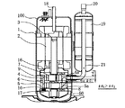
以下、本発明の実施の形態について図面を参照しながら説明する。図1はこの発明の実施の形態1を表す2気筒密閉型回転圧縮機の縦断面図である。また、図2は、この発明の実施の形態1を表す2気筒密閉型回転圧縮機の圧縮室横断面を表した図である。
Embodiment 1 FIG.
Hereinafter, embodiments of the present invention will be described with reference to the drawings. FIG. 1 is a longitudinal sectional view of a two-cylinder hermetic rotary compressor representing Embodiment 1 of the present invention. FIG. 2 is a cross-sectional view of the compression chamber of the two-cylinder hermetic rotary compressor representing the first embodiment of the present invention.

図において、密閉容器1内の上部に収納された電動要素2は、回転軸3を介して第1のシリンダである上シリンダ4、第2のシリンダである下シリンダ5内のローリングピストン9、10を回動させる。第1のシリンダである上シリンダ4と第2のシリンダである下シリンダ5との間には中間仕切板6が設けられており、第1のシリンダである上シリンダ4の開口端部(上シリンダ4に対して中間仕切板6と軸方向反対側)は主軸受16で閉塞され、第2のシリンダである下シリンダ5の開口端部(第2のシリンダ5に対して中間仕切板6と軸方向反対側)は副軸受17で閉塞されて各々圧縮室14、15が形成されている。   In the figure, the electric element 2 housed in the upper part of the hermetic container 1 includes rolling cylinders 9 and 10 in an upper cylinder 4 as a first cylinder and a lower cylinder 5 as a second cylinder via a rotating shaft 3. Rotate. An intermediate partition plate 6 is provided between the upper cylinder 4 that is the first cylinder and the lower cylinder 5 that is the second cylinder, and the opening end of the upper cylinder 4 that is the first cylinder (upper cylinder) 4, the intermediate partition plate 6 and the opposite side in the axial direction are closed by the main bearing 16, and the open end of the lower cylinder 5, which is the second cylinder (the intermediate partition plate 6 and the shaft with respect to the second cylinder 5). The side opposite to the direction) is closed by a secondary bearing 17 to form compression chambers 14 and 15, respectively.

回転軸3と一体に成形された偏心部7、8に一体に嵌合装着されたローリングピストン9、10に接するように、第1及び第2のシリンダ(上下シリンダ)内にそれぞれ収納されたベーン11、12は、スプリング13により、先端部をローリングピストン9、10の外周に圧装され、ローリングピストン9、10の回転につれて第1のシリンダである上シリンダ4、第2のシリンダである下シリンダ5にそれぞれ設けられたベーン溝4b、5b内に収納されている。そしてこのベーン11は、ベーン溝4b内を摺動して第1のシリンダである上シリンダ4と中間仕切板6と主軸受16とローリングピストン9で形成される圧縮室14内を高圧室14aと低圧室14bとに仕切っている。また、ベーン12は、ベーン溝5b内を摺動して第2のシリンダである下シリンダ5と中間仕切板6と副軸受17とローリングピストン10で形成される圧縮室15内を高圧室15aと低圧室15bとに仕切っている。   Vanes accommodated in first and second cylinders (upper and lower cylinders) so as to be in contact with rolling pistons 9 and 10 that are integrally fitted and mounted on eccentric parts 7 and 8 that are formed integrally with rotating shaft 3. Reference numerals 11 and 12 denote springs 13 whose front ends are pressed against the outer periphery of the rolling pistons 9 and 10, and as the rolling pistons 9 and 10 rotate, the first cylinder is the upper cylinder 4 and the second cylinder is the lower cylinder. 5 is accommodated in vane grooves 4b and 5b respectively provided in the same. The vane 11 slides in the vane groove 4b, and the upper cylinder 4, which is the first cylinder, the intermediate partition plate 6, the main bearing 16, and the compression piston 14 formed by the rolling piston 9, and the high pressure chamber 14a. It is partitioned into a low pressure chamber 14b. Further, the vane 12 slides in the vane groove 5b, and a high pressure chamber 15a is formed in the compression chamber 15 formed by the lower cylinder 5, which is the second cylinder, the intermediate partition plate 6, the auxiliary bearing 17, and the rolling piston 10. It is partitioned into a low pressure chamber 15b.

偏心部7、8は互いに180度位相差を設けて回転軸3に形成されている。吐出管18は圧縮室14、15から吐出された高圧の冷媒ガスを冷凍空調システムを構成する冷凍サイクル内へ送り出す。吸入管20は、密閉容器1に隣接させて設けられたアキュームレータ19と冷凍サイクルとを連結させ、第1の吸入流路4aを介して冷媒をシリンダ14、15内にそれぞれ形成された圧縮室14、15に供給する。ここで、吸入連結管21は一方のシリンダである第1のシリンダ(たとえば上シリンダ)4とアキュームレータ19とを連結し、第1のシリンダである上シリンダ4に設けられた第1の吸入流路4と連通している。第1及び第2のシリンダ4、5内のそれぞれの圧縮室14、15で圧縮された冷媒は、吐出ポート23より吐出マフラーを介して密閉容器1内に吐出される。   The eccentric parts 7 and 8 are formed on the rotating shaft 3 with a phase difference of 180 degrees from each other. The discharge pipe 18 sends out the high-pressure refrigerant gas discharged from the compression chambers 14 and 15 into the refrigeration cycle constituting the refrigeration air conditioning system. The suction pipe 20 connects an accumulator 19 provided adjacent to the hermetic container 1 and a refrigeration cycle, and a refrigerant is formed in each of the cylinders 14 and 15 through the first suction flow path 4a. , 15. Here, the suction connecting pipe 21 connects a first cylinder (for example, an upper cylinder) 4 which is one cylinder and the accumulator 19, and a first suction flow path provided in the upper cylinder 4 which is the first cylinder. 4 communicates. The refrigerant compressed in the compression chambers 14 and 15 in the first and second cylinders 4 and 5 is discharged from the discharge port 23 into the sealed container 1 through the discharge muffler.

本実施の形態では、2気筒の2つのシリンダ(第1のシリンダである上シリンダ4、第2のシリンダである下シリンダ5)のうち、どちらか一方のシリンダ(例えば第1のシリンダである上シリンダ4)にのみ吸入連結管21を挿入し、他方のシリンダ(例えば第2のシリンダである下シリンダ5)には吸入連結管21を挿入せずに一方のシリンダ(例えば第1のシリンダである上シリンダ4)の第1の吸入流路4aからシリンダ内で分岐する分岐流路(貫通穴)6aを設けて他方のシリンダ(例えば第2のシリンダである下シリンダ5)内の第2の吸入流路5aを介して他方のシリンダ(例えば第2のシリンダである下シリンダ5)の圧縮室15内に冷媒を導くようにしている。   In the present embodiment, one of the two cylinders (the upper cylinder 4 that is the first cylinder and the lower cylinder 5 that is the second cylinder) is one of the cylinders (for example, the upper that is the first cylinder). The suction connection pipe 21 is inserted only into the cylinder 4), and the other cylinder (for example, the lower cylinder 5 as the second cylinder) is inserted into one cylinder (for example, the first cylinder) without the suction connection pipe 21 being inserted. A branch passage (through hole) 6a that branches from the first suction passage 4a of the upper cylinder 4) in the cylinder is provided, and the second suction in the other cylinder (for example, the lower cylinder 5 that is the second cylinder). The refrigerant is guided into the compression chamber 15 of the other cylinder (for example, the lower cylinder 5 as the second cylinder) via the flow path 5a.

この分岐流路である貫通穴6aは、一方のシリンダ4と他方のシリンダ5との間に設けられている中間仕切板6の一方のシリンダの吸入流路4aと接する部分に設けられた貫通穴6aによって構成され、この貫通穴6aは他方のシリンダに設けられた第2の吸入流路である傾斜溝5aなどに連通しており、分岐流路6a、第2の吸入流路である傾斜溝5aを通過して第1の吸入流路4aより分岐した冷媒は第2のシリンダである下シリンダ5内の圧縮室15に取り込まれる。   The through hole 6a, which is the branch flow path, is a through hole provided in a portion of the intermediate partition plate 6 provided between one cylinder 4 and the other cylinder 5 that is in contact with the suction flow path 4a of one cylinder. 6a, and this through hole 6a communicates with an inclined groove 5a, which is a second suction channel provided in the other cylinder, and the branched channel 6a, an inclined groove, which is a second suction channel. The refrigerant that has passed through 5a and branched from the first suction flow path 4a is taken into the compression chamber 15 in the lower cylinder 5, which is the second cylinder.

また、吸入連結管21を挿入された一方のシリンダ4内に設けられた第1の吸入流路4aの流路面積よりも分岐流路6aの流路面積の方を大きくしており、また、吸入連結管21を挿入された一方のシリンダ4内に設けられた第1の吸入流路4aの流路面積よりも第2の吸入流路5aの流路面積の方を大きくしている。たとえば、第1の吸入流路4a、分岐流路6a、第2の吸入流路5aが円形の流路であり、第1の吸入流路4aの直径がφd2、分岐流路の直径がφd1、第2の吸入流路5aの直径がφd3であるとすると、φd2<φd1、φd2<φd3としている。   Further, the flow passage area of the branch flow passage 6a is larger than the flow passage area of the first suction flow passage 4a provided in the one cylinder 4 into which the suction connection pipe 21 is inserted, The flow passage area of the second suction flow passage 5a is made larger than the flow passage area of the first suction flow passage 4a provided in one cylinder 4 into which the suction connection pipe 21 is inserted. For example, the first suction channel 4a, the branch channel 6a, and the second suction channel 5a are circular channels, the diameter of the first suction channel 4a is φd2, the diameter of the branch channel is φd1, If the diameter of the second suction channel 5a is φd3, then φd2 <φd1 and φd2 <φd3.

次にその動作について説明する。電動要素2が通電されると回転軸3が回転し、一方のシリンダである第1のシリンダ4の圧縮室14内でローリングピストン9が偏心回転運動を行い、他方のシリンダである第2のシリンダ5の圧縮室15内でローリングピストン10が偏心回転運動を行う。これにより圧縮室14内に吸入連結管21から第1の吸入流路4a内に冷媒ガスが吸入され、第1のシリンダである上シリンダ4の圧縮室14内に取り込まれて圧縮される。また、第1の吸入流路4aに流入した冷媒は、中間仕切板6に設けられた分岐流路である貫通穴6aを通り第2の吸入流路である傾斜溝5aを介して第2のシリンダの圧縮室15内に取り込まれて圧縮される。   Next, the operation will be described. When the electric element 2 is energized, the rotating shaft 3 rotates, the rolling piston 9 performs eccentric rotational movement in the compression chamber 14 of the first cylinder 4 which is one cylinder, and the second cylinder which is the other cylinder. 5, the rolling piston 10 performs an eccentric rotational movement. As a result, the refrigerant gas is sucked into the compression chamber 14 from the suction connecting pipe 21 into the first suction flow path 4a, and is taken into the compression chamber 14 of the upper cylinder 4, which is the first cylinder, and compressed. The refrigerant that has flowed into the first suction flow path 4a passes through the through hole 6a that is a branch flow path provided in the intermediate partition plate 6 and passes through the inclined groove 5a that is the second suction flow path. It is taken into the compression chamber 15 of the cylinder and compressed.

圧縮室14、15でそれぞれ圧縮された冷媒ガスは、主軸受16および副軸受17にそれぞれ設けられた吐出ポート23を介して吐出マフラー50内で混合されて密閉容器1内に吐出され、密閉容器1の上部に設けられた吐出管18から冷凍空調システムを構成する冷凍サイクル内に吐出される。   The refrigerant gases compressed in the compression chambers 14 and 15 are mixed in the discharge muffler 50 through the discharge ports 23 provided in the main bearing 16 and the sub-bearing 17, respectively, and discharged into the sealed container 1. 1 is discharged into a refrigerating cycle constituting a refrigerating and air-conditioning system from a discharge pipe 18 provided at the upper portion of 1.

ここで、圧縮室14、15にはそれぞれ高圧室14a、15aと低圧室14b、15bが形成されているが、運転中の圧縮機100を停止させると、高圧室14a、15aと低圧室14b、15bの間の圧力差があるが、冷凍機油が冷媒に希釈された粘度の低い状態であるとき、この圧力差により密閉容器1内の高圧空間と圧縮室14、15との隙間および吐出ポート23を通じて冷媒ガスおよび冷凍機油が圧縮室14、15内に流入し、回転軸3を逆転させる知からが働く。   Here, high pressure chambers 14a and 15a and low pressure chambers 14b and 15b are formed in the compression chambers 14 and 15, respectively, but when the compressor 100 in operation is stopped, the high pressure chambers 14a and 15a and the low pressure chambers 14b, 15b, there is a pressure difference between the high pressure space in the hermetic container 1 and the compression chambers 14 and 15 and the discharge port 23 due to this pressure difference when the refrigerating machine oil is diluted with refrigerant and has a low viscosity. The refrigerant gas and the refrigerating machine oil flow into the compression chambers 14 and 15 through the operation of rotating the rotary shaft 3 in reverse.

しかし、第1のシリンダである上シリンダ4の吸入流路4aと第2のシリンダである下シリンダ5の吸入流路(たとえば傾斜溝)5aは第1のシリンダである上シリンダ4内より分岐流路6aにて分岐されているため、回転軸3が逆転しようとするとき逆流する冷媒ガスおよび冷凍機油はシリンダ4内の吸入流路4a内にて合流する。このとき圧縮室14と圧縮室15の双方から逆流しようとする冷媒ガスおよび冷凍機油が吸入流路4a内にて合流することにより、吸入流路4a内での流動抵抗が大きくなり、吸入連結管21を通じたアキュームレータへの逆流を抑制することができる。   However, the suction flow path 4a of the upper cylinder 4 serving as the first cylinder and the suction flow path (for example, the inclined groove) 5a of the lower cylinder 5 serving as the second cylinder branch from the inside of the upper cylinder 4 serving as the first cylinder. Since it is branched in the path 6 a, the refrigerant gas and the refrigerating machine oil that flow backward when the rotating shaft 3 tries to reversely join together in the suction flow path 4 a in the cylinder 4. At this time, the refrigerant gas and the refrigerating machine oil that are going to flow backward from both the compression chamber 14 and the compression chamber 15 merge in the suction flow path 4a, so that the flow resistance in the suction flow path 4a increases and the suction connection pipe The backflow to the accumulator through 21 can be suppressed.

通常運転時において第2のシリンダである下シリンダ5の吸入流路5aは第1のシリンダである上シリンダ4内から分岐流路6aにより分岐された構造であるため、吸入効率が悪化する傾向になるが、分岐流路である貫通穴の直径φd1、あるいは第2のシリンダである下シリンダ5の吸入流路5aの直径を第1のシリンダである上シリンダ4の吸入流路の直径φd2より大径とすることで、第2のシリンダである下シリンダ5への吸入流路が拡大でき吸入効率を向上させることができる。   During normal operation, the suction flow path 5a of the lower cylinder 5 serving as the second cylinder has a structure branched from the upper cylinder 4 serving as the first cylinder by the branch flow path 6a, and therefore suction efficiency tends to deteriorate. However, the diameter φd1 of the through-hole that is the branch flow path or the diameter of the suction flow path 5a of the lower cylinder 5 that is the second cylinder is larger than the diameter φd2 of the suction flow path of the upper cylinder 4 that is the first cylinder. By setting the diameter, the suction flow path to the lower cylinder 5 as the second cylinder can be expanded, and the suction efficiency can be improved.

第2のシリンダである下シリンダ5への分岐流路6aの直径φd1をパラメータとして変化させて検証した結果、第2のシリンダである下シリンダ5への分岐流路6aの直径φd1を第1のシリンダである上シリンダ4の吸入流路4aの直径φd2より10%以上大径とすることで、第2のシリンダである下シリンダ5の吸入効率も第1のシリンダである上シリンダ4と同等以上の吸入効率を確保することができることがわかった。   As a result of changing the diameter φd1 of the branch flow path 6a to the lower cylinder 5 which is the second cylinder as a parameter, the diameter φd1 of the branch flow path 6a to the lower cylinder 5 which is the second cylinder is changed to the first cylinder. By making the diameter φd2 or more larger than the diameter φd2 of the suction flow path 4a of the upper cylinder 4 serving as the cylinder, the suction efficiency of the lower cylinder 5 serving as the second cylinder is equal to or greater than that of the upper cylinder 4 serving as the first cylinder. It was found that the inhalation efficiency of can be ensured.

図1においては、吸入連結管21が第1のシリンダである上シリンダ4内に挿入されており、第1のシリンダである上シリンダ4内の吸入流路4aから中間仕切板6に設けられた分岐流路である貫通穴6a、および第2のシリンダである下シリンダ5内の吸入流路である傾斜溝5aを介して冷媒を第2のシリンダである下シリンダ5の圧縮室15へ導いているが、逆に第2のシリンダである下シリンダ5に吸入連結管21を挿入し、第1のシリンダである上シリンダ4の吸入流路4aを、第2のシリンダである下シリンダ5内の吸入流路5aから中間仕切板6の分岐流路である貫通穴6aを通じて第1のシリンダである上シリンダ4内に設けられた傾斜溝を介して圧縮室14内に冷媒を導くようにしてもよい。また、第2のシリンダである下シリンダ5の吸入流路5aを第1のシリンダである上シリンダ4の吸入流路4aより流路面積を大きくした仕様としているが、第1のシリンダである上シリンダ4の吸入流路4aを第2のシリンダである下シリンダ5の吸入流路5aより流路面積を大きくした仕様においても同様に、回転軸3の逆転を防止することができるなど同等の効果を得ることができる。   In FIG. 1, the suction connecting pipe 21 is inserted into the upper cylinder 4 as the first cylinder, and is provided in the intermediate partition plate 6 from the suction flow path 4a in the upper cylinder 4 as the first cylinder. The refrigerant is guided to the compression chamber 15 of the lower cylinder 5 serving as the second cylinder through the through hole 6a serving as the branch channel and the inclined groove 5a serving as the suction channel in the lower cylinder 5 serving as the second cylinder. On the contrary, the suction connecting pipe 21 is inserted into the lower cylinder 5 which is the second cylinder, and the suction flow path 4a of the upper cylinder 4 which is the first cylinder is placed in the lower cylinder 5 which is the second cylinder. The refrigerant may be guided into the compression chamber 14 from the suction flow path 5a through an inclined groove provided in the upper cylinder 4 as the first cylinder through the through hole 6a that is a branch flow path of the intermediate partition plate 6. Good. The suction passage 5a of the lower cylinder 5 serving as the second cylinder is designed to have a larger passage area than the suction passage 4a of the upper cylinder 4 serving as the first cylinder. Similarly, in the specification in which the suction passage 4a of the cylinder 4 has a larger passage area than the suction passage 5a of the lower cylinder 5 which is the second cylinder, it is possible to prevent reverse rotation of the rotary shaft 3 and the like. Can be obtained.

以上のように本実施の形態に示した2気筒密閉型回転圧縮機では、2つのシリンダ(第1のシリンダ4、第2のシリンダ5)のどちらか一方のシリンダ(たとえば第1のシリンダ)にのみ吸入連結管21を挿入し、他方のシリンダ(たとえば第2のシリンダ)へはシリンダ内で分岐する分岐流路6aを設けて冷媒を導くと共に、分岐流路6aが中間仕切板6を貫通する貫通穴で構成され、吸入連結管21を挿入された一方のシリンダ(たとえば第1のシリンダ4)内に設けられた吸入流路4aより分岐流路6aの流路面積を大きくしたことにより、一方のシリンダ(たとえば第1のシリンダ4)内の吸入流路4a内で、双方のシリンダ4、5から逆流しようとする冷媒ガスおよび冷凍機油が合流するため、吸入流路4a内での流動抵抗が増大し、冷媒が逆流しにくくなり、冷凍機油が冷媒に希釈された粘度の低い状態での運転停止時であっても回転軸3の逆転を抑制でき、密閉容器1内の冷凍機油の冷凍空調システムを構成する冷凍サイクル内への流入を防止することができ、油枯渇の発生しにくい信頼性の高い2気筒密閉型回転圧縮機を提供することができる。   As described above, in the two-cylinder hermetic rotary compressor shown in the present embodiment, either one of the two cylinders (the first cylinder 4 and the second cylinder 5) (for example, the first cylinder) is used. Only the suction connection pipe 21 is inserted, and a branch flow path 6a that branches into the other cylinder (for example, the second cylinder) is provided to guide the refrigerant, and the branch flow path 6a passes through the intermediate partition plate 6. By making the flow passage area of the branch flow passage 6a larger than the suction flow passage 4a provided in one cylinder (for example, the first cylinder 4) which is configured by a through hole and into which the suction connection pipe 21 is inserted, In the suction flow path 4a in the cylinder (for example, the first cylinder 4), the refrigerant gas and the refrigerating machine oil that are going to flow backward from both the cylinders 4 and 5 merge, so that the flow resistance in the suction flow path 4a is reduced. Increase The refrigerant is less likely to flow backward, and the reversal of the rotating shaft 3 can be suppressed even when the operation is stopped in a state where the refrigerant oil is diluted with the refrigerant and the viscosity is low. It is possible to provide a highly reliable two-cylinder hermetic rotary compressor that can prevent inflow into the refrigeration cycle to be configured and is less likely to cause oil exhaustion.

実施の形態2.
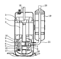
以下、本発明の実施の形態2を表す2気筒密閉型回転圧縮機について説明する。図3はこの発明の実施の形態2を表す圧縮機の断面図である。また図4は、この発明の実施の形態2を表す圧縮機の図3で示した2気筒密閉形回転圧縮機の別角度から見た要部縦断面図である。図において、実施の形態1や図1、図2と同等部分は、同一符号を付して詳細な説明を省略する。
Embodiment 2. FIG.
Hereinafter, a two-cylinder hermetic rotary compressor representing the second embodiment of the present invention will be described. 3 is a cross-sectional view of a compressor representing Embodiment 2 of the present invention. FIG. 4 is a longitudinal sectional view of a main part of the compressor representing the second embodiment of the present invention as seen from another angle of the two-cylinder hermetic rotary compressor shown in FIG. In the figure, the same parts as those of the first embodiment, FIG. 1 and FIG.

本実施の形態では、第1のシリンダあるいは第2のシリンダのうちのどちらか一方のシリンダにのみ吸入連結管21を挿入し、他方のシリンダへはシリンダ内で分岐する分岐流路6aを設けて冷媒を導くと共に、どちらか一方のシリンダ(たとえば第1のシリンダ)にのみ、シリンダ内を回転するローリングピストン(たとえばローリングピストン9)にベーン(たとえばベーン11)を背部より押圧するスプリング13を設け、他方のシリンダにはベーン(例えばベーン12)を押圧するスプリングを設けないようにしている。   In the present embodiment, the suction connecting pipe 21 is inserted only into one of the first cylinder and the second cylinder, and the branch flow path 6a that branches in the cylinder is provided to the other cylinder. In addition to guiding the refrigerant, only one of the cylinders (for example, the first cylinder) is provided with a spring 13 for pressing the vane (for example, the vane 11) from the back to the rolling piston (for example, the rolling piston 9) that rotates in the cylinder, The other cylinder is not provided with a spring for pressing the vane (for example, the vane 12).

図3において、2気筒密閉型回転圧縮機の密閉容器1内は電動要素2と、回転軸3、第1のシリンダである上シリンダ4、第2のシリンダである下シリンダ5、回転軸3と一体に成形された偏心部7、8、ローリングピストン9、10、ベーン11、12から構成されている。また、図4に示すように、本実施の形態では、第1のシリンダである上シリンダ4にはスプリング13が設けられていて、ベーン11をローリングピストン9側に押圧している。またベーン11の背面には高圧圧力が加わっているので、この高圧圧力によってもベーン11は押圧されている。第2のシリンダである下シリンダ5には、ベーン12をローリングピストン10側に押圧するスプリングが設けられておらず、ベーン12は背面に加わっている高圧圧力のみである。   In FIG. 3, the sealed container 1 of the two-cylinder hermetic rotary compressor has an electric element 2, a rotating shaft 3, an upper cylinder 4 that is a first cylinder, a lower cylinder 5 that is a second cylinder, and a rotating shaft 3. It is comprised from the eccentric parts 7 and 8 shape | molded integrally, the rolling pistons 9 and 10, and the vanes 11 and 12. FIG. As shown in FIG. 4, in the present embodiment, the upper cylinder 4 that is the first cylinder is provided with a spring 13 to press the vane 11 toward the rolling piston 9. Further, since a high pressure is applied to the back surface of the vane 11, the vane 11 is pressed by the high pressure. The lower cylinder 5, which is the second cylinder, is not provided with a spring that presses the vane 12 toward the rolling piston 10, and the vane 12 is only high pressure applied to the back surface.

以上のように構成された2気筒密閉型回転圧縮機について、以下その動作を説明する。電動要素2が通電されると回転軸3が回転し、第1のシリンダである上シリンダ4に形成される圧縮室14内でローリングピストン9が偏心回転運動を行い、第2のシリンダである下シリンダ5に形成される圧縮室15内でローリングピストン10が偏心回転運動を行う。これにより圧縮室14、15内に冷凍空調システムを構成する冷凍サイクル内から吸入連結管21を通じて冷媒ガスが吸入され圧縮が行われる。   The operation of the two-cylinder hermetic rotary compressor configured as described above will be described below. When the electric element 2 is energized, the rotary shaft 3 rotates, and the rolling piston 9 performs eccentric rotational movement in the compression chamber 14 formed in the upper cylinder 4 that is the first cylinder, and the lower cylinder that is the second cylinder. The rolling piston 10 performs an eccentric rotational motion in a compression chamber 15 formed in the cylinder 5. As a result, the refrigerant gas is sucked into the compression chambers 14 and 15 from the refrigeration cycle constituting the refrigeration air-conditioning system through the suction connection pipe 21 and compressed.

運転中の圧縮機を停止させると、高圧室14a、15aと低圧室14b、15bの間に圧力差が残る。ここで本実施の形態では、第1のシリンダである上シリンダ4内の圧縮室14ではこの圧力差以外にスプリング13による振幅力が発生しているが、第2のシリンダである下シリンダ5内の圧縮室15ではスプリングが存在しないため、高圧室15aと低圧室15bの圧力差以外に力は作用しない。   When the compressor in operation is stopped, a pressure difference remains between the high pressure chambers 14a and 15a and the low pressure chambers 14b and 15b. Here, in the present embodiment, in the compression chamber 14 in the upper cylinder 4 which is the first cylinder, an amplitude force is generated by the spring 13 in addition to this pressure difference, but in the lower cylinder 5 which is the second cylinder. Since there is no spring in the compression chamber 15, no force acts other than the pressure difference between the high pressure chamber 15a and the low pressure chamber 15b.

これにより圧縮室14内で回転軸3の偏心部7に作用する力と、圧縮室15内で回転軸3の偏心部8に作用する力は異なり、回転軸3を逆転させようとする力がアンバランスになるため逆転することはない。ここで、圧縮室14と圧縮室15のそれぞれのベーン11、12に両方ともにスプリング13が設けられていると、偏心部7、8が180度ずれて設けられているため、一方のスプリングが伸びきって安定した状態では、他方のスプリングが圧縮されて不安定な状態になり、スプリングにアンバランスが発生し、今度は圧縮されている他方のスプリングが伸びきろうとするため、逆転しようとしてアンバランスが解消せず、永久に回転軸3は回転(逆転)しつづけようとする。しかし、本実施の形態では、一方のベーン11のみにスプリング13を設け、他方のベーン12にはスプリングを設けないようにしているので、一方のシリンダ4のスプリング13が伸びきった状態で安定するため、回転軸3は安定し、回転軸3の逆転が抑制される。   As a result, the force acting on the eccentric portion 7 of the rotating shaft 3 in the compression chamber 14 is different from the force acting on the eccentric portion 8 of the rotating shaft 3 in the compression chamber 15, and the force for reversing the rotating shaft 3 is different. Since it becomes unbalanced, there is no reverse. Here, if the springs 13 are provided in the vanes 11 and 12 of the compression chamber 14 and the compression chamber 15 respectively, the eccentric portions 7 and 8 are provided 180 degrees apart from each other. In a very stable state, the other spring is compressed and becomes unstable, causing an unbalance in the spring, and this time the other spring that is compressed tries to stretch, so it tries to reverse. However, the rotation shaft 3 continues to rotate (reverse) forever. However, in the present embodiment, the spring 13 is provided only on one vane 11 and the spring is not provided on the other vane 12, so that the spring 13 of one cylinder 4 is fully extended. Therefore, the rotating shaft 3 is stabilized and the reverse rotation of the rotating shaft 3 is suppressed.

また、本実施の形態では、第2のシリンダである下シリンダ5内にベーン12を押圧するスプリングを挿入していない。通常運転時は回転軸3が回転を始めると第1のシリンダである上シリンダ4内の圧縮室14では、ベーン11が背部からスプリング13の振幅力によりローリングピストンに押圧されるため、高圧室14aと低圧室15aとが仕切られて、圧縮が行われると共に吐出ポート23から吐出マフラー50を介して密閉容器1内に吐出される。この密閉容器1内に吐出された高圧の冷媒ガスにより第2のシリンダである下シリンダ5内のベーン12は背部から密閉容器1内の高圧圧力によりローリングピストン10側に押圧されるので、第2のシリンダである下シリンダ5内においても高圧室14bと低圧室15bとがベーン12を押圧するスプリングを備えてなくてもベーン12により仕切られて、圧縮が正常に行われる。   In the present embodiment, a spring that presses the vane 12 is not inserted into the lower cylinder 5 that is the second cylinder. In the normal operation, when the rotating shaft 3 starts rotating, in the compression chamber 14 in the upper cylinder 4, which is the first cylinder, the vane 11 is pressed from the back to the rolling piston by the amplitude force of the spring 13, and thus the high pressure chamber 14a. And the low-pressure chamber 15a are partitioned, compressed, and discharged from the discharge port 23 into the sealed container 1 through the discharge muffler 50. The vane 12 in the lower cylinder 5 as the second cylinder is pressed from the back to the rolling piston 10 side by the high pressure in the sealed container 1 due to the high-pressure refrigerant gas discharged into the sealed container 1. Even in the lower cylinder 5, which is the cylinder, the high pressure chamber 14 b and the low pressure chamber 15 b are partitioned by the vane 12 without being provided with a spring that presses the vane 12, and compression is normally performed.

図4においては、第1のシリンダである上シリンダ4にのみスプリング13を設け、第2のシリンダである下シリンダ5にはスプリングを設けない仕様としているが、逆に第2のシリンダである下シリンダ5にのみスプリング13を設け、第1のシリンダである上シリンダ4にスプリングを設けない仕様にしても同様に、回転軸3の逆転を防止することができる。   In FIG. 4, the spring 13 is provided only in the upper cylinder 4 as the first cylinder and the spring is not provided in the lower cylinder 5 as the second cylinder, but conversely the lower cylinder as the second cylinder. Similarly, the reverse rotation of the rotary shaft 3 can be prevented even if the spring 13 is provided only in the cylinder 5 and the upper cylinder 4 as the first cylinder is not provided with a spring.

以上のように本実施の形態の2気筒密閉型回転圧縮機では、2つの(上下)シリンダのうちどちらか一方のシリンダにのみ吸入連結管21を挿入し、他方のシリンダへはシリンダ内で分岐する分岐流路6aを設け冷媒を導くと共に、どちらか一方のシリンダにのみ、シリンダ内を回転するローリングピストンにベーンを背部より押圧するスプリングを設け、他方のシリンダにはスプリングを設けないようにしている。   As described above, in the two-cylinder hermetic rotary compressor of the present embodiment, the suction connection pipe 21 is inserted into only one of the two (upper and lower) cylinders, and the other cylinder is branched in the cylinder. A branch flow path 6a is provided to guide the refrigerant, and only one of the cylinders is provided with a spring that presses the vane from the back of the rolling piston that rotates in the cylinder, and the other cylinder is not provided with a spring. Yes.

したがって、2つの(第1および第2の)シリンダ内のそれぞれの圧縮室14、15は、お互いに180度ずれて形成されていることにより回転軸の偏心部に作用するスプリングの伸張力がアンバランスになるのを抑制でき、圧縮機運転停止時における回転軸の逆転を防止でき、密閉容器1内の冷凍機油の冷凍空調システムを構成する冷凍サイクル内への流出を防止することができ、油枯渇のない信頼性の高い2気筒密閉型回転圧縮機を提供することができる。また、実施の形態1で説明したように冷凍機油が冷媒に希釈された粘度の低い状態であっても、回転軸3の逆転を防止でき、油枯渇のない信頼性の高い2気筒密閉型回転圧縮機を提供することができる。   Therefore, the compression chambers 14 and 15 in the two (first and second) cylinders are formed so as to be shifted from each other by 180 degrees, so that the extension force of the spring acting on the eccentric portion of the rotating shaft is unbalanced. The balance can be suppressed, the reversal of the rotating shaft when the compressor is stopped, the refrigerating machine oil in the hermetic container 1 can be prevented from flowing into the refrigerating cycle constituting the refrigerating air conditioning system, A highly reliable two-cylinder hermetic rotary compressor without exhaustion can be provided. Further, as described in the first embodiment, even when the refrigerating machine oil is diluted with a refrigerant and in a low viscosity state, the rotation of the rotary shaft 3 can be prevented, and a highly reliable two-cylinder sealed rotation without oil depletion. A compressor can be provided.

実施の形態3.
以下、本発明の実施の形態3を表す2気筒密閉型回転圧縮機について図面を参照しながら説明する。図5は本発明の実施の形態3を表す圧縮機の縦断面図である。また、図6は分岐流路に設けられた逆止弁の挙動を説明するために図であり、図6aは通常運転時における逆止弁の挙動を表した図であり、図6bは冷媒ガスおよび冷凍機油の逆流発生時における逆止弁の挙動を表した図である。図において、実施の形態1、2、および図1〜図4と同等部分は同一符号を付して説明は省略する。本実施の形態では、2つ(第1および第2)のシリンダ4、5のうちどちらか一方のシリンダ(たとえば第1のシリンダ4)にのみ吸入連結管を挿入し、他方のシリンダ(たとえば第2のシリンダ5)へはシリンダ内で分岐する分岐流路6aを設けて冷媒を導くと共に、この分岐流路6aに逆止弁24を設けて冷媒の逆流を防止するようにしている。
Embodiment 3 FIG.
Hereinafter, a two-cylinder hermetic rotary compressor representing the third embodiment of the present invention will be described with reference to the drawings. FIG. 5 is a longitudinal sectional view of a compressor representing the third embodiment of the present invention. 6 is a diagram for explaining the behavior of the check valve provided in the branch flow path, FIG. 6a is a diagram showing the behavior of the check valve during normal operation, and FIG. 6b is a refrigerant gas. It is a figure showing the behavior of the check valve when the reverse flow of the refrigeration oil occurs. In the figure, the same parts as those in Embodiments 1 and 2 and FIGS. In the present embodiment, the suction connecting pipe is inserted only into one of the two (first and second) cylinders 4 and 5 (for example, the first cylinder 4), and the other cylinder (for example, the first cylinder 4). The second cylinder 5) is provided with a branch flow path 6a that branches in the cylinder to guide the refrigerant, and a check valve 24 is provided in the branch flow path 6a to prevent back flow of the refrigerant.

図において、2気筒密閉型回転圧縮機の密閉容器1内は電動要素2と、回転軸3、第1のシリンダである上シリンダ4、第2のシリンダである下シリンダ5、回転軸3と一体に成形された偏心部7、8、ローリングピストン9、10、そしてベーン11、12から構成される。また第2のシリンダである下シリンダ5内への分岐流路6aは、逆止弁24、および逆止弁スプリング25を介して直角に構成されて、分岐流路6aを開閉するように構成されている。なお、圧縮機100の停止時の逆止弁24は逆止弁スプリング25の振幅力により、中間仕切板6に設けられた分岐流路である貫通穴6aの端面に押しつけられてシールし、第1のシリンダである上シリンダ4の吸入流路と第2のシリンダである下シリンダ5内の吸入流路を仕切った状態になっている。   In the figure, a sealed container 1 of a two-cylinder hermetic rotary compressor has an electric element 2, a rotating shaft 3, an upper cylinder 4 that is a first cylinder, a lower cylinder 5 that is a second cylinder, and a rotating shaft 3. Are formed of eccentric parts 7 and 8, rolling pistons 9 and 10, and vanes 11 and 12. The branch flow path 6a into the lower cylinder 5, which is the second cylinder, is configured at right angles via a check valve 24 and a check valve spring 25, and is configured to open and close the branch flow path 6a. ing. When the compressor 100 is stopped, the check valve 24 is pressed against the end face of the through hole 6a which is a branch flow path provided in the intermediate partition plate 6 by the amplitude force of the check valve spring 25, and is sealed. The suction flow path of the upper cylinder 4 that is one cylinder and the suction flow path in the lower cylinder 5 that is the second cylinder are partitioned.

以下その動作を説明する。電動要素2が通電されて回転軸3が回転すると、第1のシリンダ4および第2のシリンダ5のそれぞれの圧縮室14、15内でローリングピストン9、10が偏芯回転運動を行う。これにより圧縮室14、15内に冷凍空調システムを構成する冷凍サイクルから吸入連結管21を通じて冷媒ガスが吸入されて圧縮が行われる。このとき図6aのように、通常運転中は、吸入された冷媒ガスの圧力により、逆止弁スプリング25に抗して第2のシリンダである下シリンダ5内の逆止弁24は押し下げられる。   The operation will be described below. When the electric element 2 is energized and the rotating shaft 3 rotates, the rolling pistons 9 and 10 perform eccentric rotational movement in the compression chambers 14 and 15 of the first cylinder 4 and the second cylinder 5, respectively. As a result, the refrigerant gas is sucked into the compression chambers 14 and 15 from the refrigerating cycle constituting the refrigerating and air-conditioning system through the suction connecting pipe 21 to be compressed. At this time, as shown in FIG. 6a, during normal operation, the check valve 24 in the lower cylinder 5, which is the second cylinder, is pushed down against the check valve spring 25 by the pressure of the sucked refrigerant gas.

ここで、運転中の圧縮機100を停止させると、高圧室14a、15aと低圧室14b、15bの間に圧力差が残るため、その圧力差により冷媒ガスおよび冷凍機油が逆流し、回転軸3を逆転させようとする。特に、冷凍機油が冷媒に希釈された粘度の低い状態であるときが、冷媒漏れが発生しやすいため逆転しやすい。   Here, when the compressor 100 in operation is stopped, a pressure difference remains between the high pressure chambers 14a and 15a and the low pressure chambers 14b and 15b, so that the refrigerant gas and the refrigerating machine oil flow backward due to the pressure difference, and the rotating shaft 3 Try to reverse. In particular, when the refrigerating machine oil is in a low-viscosity state diluted with a refrigerant, the refrigerant easily leaks and easily reverses.

しかし、第2のシリンダである下シリンダ5の第2の吸入流路5aから第1のシリンダである上シリンダ4の第1の吸入流路4aを介してアキュームレータ19へ逆流しようとする冷媒ガスおよび冷凍機油は、逆止弁スプリング25の振幅力と圧力差により逆止弁24が直ちに中間仕切板6の下端面に押しつけられて中間仕切板6に設けられた分岐流路6aが閉塞されるので、冷媒や冷凍機油の逆流が阻止され、さらに2気筒密閉型回転圧縮機において起こる停止時の逆転現象を防止することができる。   However, the refrigerant gas which tends to flow backward from the second suction flow path 5a of the lower cylinder 5 as the second cylinder to the accumulator 19 via the first suction flow path 4a of the upper cylinder 4 as the first cylinder, and In the refrigeration oil, the check valve 24 is immediately pressed against the lower end surface of the intermediate partition plate 6 by the amplitude force and pressure difference of the check valve spring 25, and the branch flow path 6a provided in the intermediate partition plate 6 is closed. Further, the reverse flow of the refrigerant and the refrigerating machine oil is prevented, and further, the reverse rotation phenomenon at the time of stoppage that occurs in the two-cylinder sealed rotary compressor can be prevented.

図5においては、吸入連結管21が第1のシリンダである上シリンダ4内に挿入されていて、第1のシリンダである上シリンダ4内の吸入流路4aから中間仕切板6の分岐流路である貫通穴6aを通じて第2のシリンダである下シリンダ5の吸入流路に分岐するようにして、逆止弁24および逆止弁スプリング25を第2のシリンダである下シリンダ5の第2の吸入流路5a中に設けた仕様としているが、逆に吸入連結管21が第2のシリンダである下シリンダ5内に挿入されていて、第1のシリンダである上シリンダ4の第1の吸入流路4aを、第2のシリンダである下シリンダ5内の第2の吸入流路から中間仕切板6の分岐流路であるである貫通穴6aを通じて分岐して、逆止弁24および逆止弁スプリング25を第1のシリンダである上シリンダ4の第1の吸入流路4a途中に設けた仕様においても同様の効果を有し、回転軸3の逆転を防止することができる。   In FIG. 5, the suction connecting pipe 21 is inserted into the upper cylinder 4 which is the first cylinder, and the branch flow path of the intermediate partition plate 6 from the suction flow path 4a in the upper cylinder 4 which is the first cylinder. The check valve 24 and the check valve spring 25 are connected to the second cylinder of the lower cylinder 5 as the second cylinder by branching to the suction flow path of the lower cylinder 5 as the second cylinder through the through hole 6a. Although the specification is provided in the suction flow path 5a, the suction connection pipe 21 is inserted into the lower cylinder 5 which is the second cylinder, and the first suction of the upper cylinder 4 which is the first cylinder. The flow path 4a is branched from the second suction flow path in the lower cylinder 5 which is the second cylinder through the through hole 6a which is the branch flow path of the intermediate partition plate 6, and the check valve 24 and the check valve The valve spring 25 is the first cylinder Has the same effect in specifications provided in the middle first suction passage 4a of the cylinder 4, it is possible to prevent the reverse rotation of the rotary shaft 3.

以上のように本実施の形態に示す2気筒密閉型回転圧縮機では、2つのシリンダ(第1のシリンダである上シリンダ4、第2のシリンダである下シリンダ5)のうちどちらか一方のシリンダ(たとえば第1のシリンダ4)にのみ吸入連結管21を挿入し、他方のシリンダ(たとえば第2のシリンダ5)にはシリンダ内で分岐する第2の吸入流路5aを設けて冷媒を導くと共に、第2の吸入流路5aに逆止弁24を設けることにより、冷媒ガスおよび冷凍機油がシリンダの第1および第2の吸入流路4a、5aを通じてアキュームレータ19へ逆流しようとしても、逆止弁スプリング25の振幅力と圧力差により逆止弁24が直ちに中間仕切板6の分岐流路である貫通穴6aを塞ぐように端面に押しつけられるため、2気筒密閉型回転圧縮機において起こる停止時の逆転現象を防止することができ、信頼性の高い2気筒密閉型回転圧縮機を提供することができる。   As described above, in the two-cylinder hermetic rotary compressor shown in the present embodiment, one of the two cylinders (the upper cylinder 4 that is the first cylinder and the lower cylinder 5 that is the second cylinder). The suction connecting pipe 21 is inserted only into the first cylinder 4 (for example, the first cylinder 4), and the second cylinder 5 (for example, the second cylinder 5) is provided with a second suction passage 5a that branches in the cylinder to guide the refrigerant. By providing the check valve 24 in the second suction flow path 5a, even if the refrigerant gas and the refrigerating machine oil try to flow back to the accumulator 19 through the first and second suction flow paths 4a and 5a of the cylinder, the check valve The check valve 24 is immediately pressed against the end face so as to close the through hole 6a which is the branch flow path of the intermediate partition plate 6 due to the amplitude force and pressure difference of the spring 25, so that the two-cylinder hermetic rotary compressor is used. Reversals during arrest have been caused can be prevented, it is possible to provide a highly reliable two-cylinder sealed type rotary compressor.

なお、実施の形態1〜実施の形態3において使用される冷媒としては、たとえば、R410A、R407C等のHFC冷媒であり、圧縮機構部の潤滑を行う冷凍機油としては、アルキルベンゼン等のHFC系冷媒と非相溶、もしくは弱相溶油を使用するようにしている。   In addition, as a refrigerant | coolant used in Embodiment 1-Embodiment 3, it is HFC refrigerant | coolants, such as R410A, R407C, for example, As refrigerating machine oil which lubricates a compression mechanism part, HFC type refrigerant | coolants, such as alkylbenzene, Incompatible or weakly compatible oil is used.

運転中の圧縮機が停止すると、高圧室14a、15aと低圧室14b、15bの間にはそれぞれ圧力差が残り、低圧室14b、15bは、密閉容器1内の圧力、及び高圧室14a、15a内の圧力に比べて圧力が低いため、圧力差により密閉容器1内の高圧空間及び高圧室14a、15a内と低圧室14b、15bとの間の隙間を通じて高圧の冷媒ガスおよび冷凍機油が低圧室14b、15b内や低圧空間に流入しようとする。   When the compressor in operation stops, a pressure difference remains between the high pressure chambers 14a and 15a and the low pressure chambers 14b and 15b. The low pressure chambers 14b and 15b have the pressure in the sealed container 1 and the high pressure chambers 14a and 15a. Since the pressure is lower than the internal pressure, the high pressure refrigerant gas and the refrigerating machine oil are supplied to the low pressure chamber through the high pressure space in the sealed container 1 and the gap between the high pressure chambers 14a and 15a and the low pressure chambers 14b and 15b due to the pressure difference. 14b, 15b or the low pressure space.

特に冷媒と相溶する相溶油を使用した場合に、冷凍機油が冷媒で希釈されていると冷凍機油の粘度が低くなり漏れやすくなるが、本実施の形態では、冷凍機油はアルキルベンゼン等のHFC系冷媒と非相溶もしくは弱相溶油であるため、冷凍機油が冷媒に希釈されることがなく、冷凍機油の粘度は高いままであることと、密閉容器1内の高圧空間と圧縮室14、15との隙間が極めて小さいことから、冷媒ガスおよび冷凍機油は圧縮室14、15内に漏れて流入することが起こらない。よって、漏れによる逆転現象が発生しにくく、異常音や軸受け焼き付きなどの起こらない低騒音で信頼性の高い圧縮機が得られる。   In particular, when a compatible oil that is compatible with the refrigerant is used, if the refrigerating machine oil is diluted with the refrigerant, the viscosity of the refrigerating machine oil becomes low and easily leaks, but in this embodiment, the refrigerating machine oil is an HFC such as alkylbenzene. Since the refrigerant is incompatible or weakly compatible with the refrigerant, the refrigerating machine oil is not diluted with the refrigerant, the refrigerating machine oil remains high in viscosity, the high-pressure space in the sealed container 1 and the compression chamber 14. The refrigerant gas and the refrigeration oil do not leak into the compression chambers 14 and 15 and flow into the compression chambers 14 and 15. Therefore, a reversible phenomenon due to leakage is unlikely to occur, and a highly reliable compressor with low noise that does not cause abnormal noise or bearing seizure can be obtained.

以上のように本実施の形態の2気筒密閉型回転圧縮機では、冷媒がR410A、R407C等のHFC系冷媒であり、冷凍機油がアルキルベンゼン等のHFC冷媒と非相溶もしくは弱相溶油であるために、2気筒密閉型回転圧縮機において起こる停止時の逆転現象を防止することができ、低騒音で信頼性の高い2気筒密閉型回転圧縮機を提供することができる。   As described above, in the two-cylinder hermetic rotary compressor of the present embodiment, the refrigerant is an HFC refrigerant such as R410A and R407C, and the refrigerator oil is incompatible or weakly compatible with an HFC refrigerant such as alkylbenzene. Therefore, it is possible to prevent a reverse rotation phenomenon at the time of stopping that occurs in the two-cylinder hermetic rotary compressor, and to provide a low-noise and high-reliability two-cylinder hermetic rotary compressor.

以上、実施の形態1〜3にて説明したように、第1のシリンダ4内に第1のローリングピストン9を配設し、第2のシリンダ5内に第2のローリングピストン10を配設した2気筒回転式圧縮機において、第1のシリンダ4に設けられ、第1のシリンダ4内を高圧室14aと低圧室14bに仕切る第1のベーン11と、第2のシリンダ5に設けられ、第2のシリンダ5内を高圧室15aと低圧室15bに仕切る第2のベーン12と、を備え、第1のベーン11には第1のローリングピストン9に押圧するスプリング13を設け、第2のベーン12には第2のローリングピストン10に押圧するスプリングを設けないようにしたので、回転軸の偏心部に作用するスプリングの伸張力がアンバランスになるのを抑制でき、圧縮機運転停止時における回転軸の逆転を防止でき、密閉容器1内の冷凍機油の冷凍空調システムを構成する冷凍サイクル内への流出を防止することができ、油枯渇のない信頼性の高い2気筒密閉型回転圧縮機を提供することができる。また、冷凍機油が冷媒に希釈された粘度の低い状態であっても、回転軸3の逆転を防止でき、油枯渇のない信頼性の高い2気筒密閉型回転圧縮機を提供することができる。   As described above in the first to third embodiments, the first rolling piston 9 is disposed in the first cylinder 4 and the second rolling piston 10 is disposed in the second cylinder 5. In the two-cylinder rotary compressor, the first vane 11 is provided in the first cylinder 4 and partitions the first cylinder 4 into the high pressure chamber 14a and the low pressure chamber 14b, and the second cylinder 5 is provided. And a second vane 12 that partitions the inside of the cylinder 5 into a high pressure chamber 15a and a low pressure chamber 15b. The first vane 11 is provided with a spring 13 that presses against the first rolling piston 9, and the second vane 12 is not provided with a spring that presses against the second rolling piston 10, so that it is possible to suppress the unbalanced extension force of the spring acting on the eccentric part of the rotating shaft, and when the compressor is stopped. A reliable two-cylinder sealed rotary compressor that can prevent reversal of the rotating shaft, can prevent the refrigeration oil in the hermetic container 1 from flowing out into the refrigeration cycle constituting the refrigeration air conditioning system, and has no oil depletion. Can be provided. In addition, even when the refrigeration oil is diluted with a refrigerant and has a low viscosity, it is possible to provide a highly reliable two-cylinder hermetic rotary compressor that can prevent the rotation of the rotating shaft 3 and that does not run out of oil.

また、密閉容器内に2つの第1および第2のシリンダ4、5および2つのローリングピストン9、10が軸線方向に重ねて配設された2気筒回転式圧縮機において、2つのシリンダ4、5のうち一方のシリンダ(たとえば第1のシリンダ4)にのみ設けられ、密閉容器1外より冷媒を吸入して一方のシリンダ(たとえば第1のシリンダ4)内の圧縮室14に第1の吸入流路4aを介して冷媒を導く1つの吸入連結管21と、第1の吸入流路4aより分岐し、吸入連結管より吸入された冷媒を前記他方のシリンダ(たとえば第2のシリンダ5)の圧縮室15内へ導く第2の吸入流路(たとえば第2の吸入流路5aあるいは分岐流路6a)と、を備え、第1の吸入流路の流路面積と第2の吸入流路(たとえば第2の吸入流路5aあるいは分岐流路6a)の流路面積の合計が吸入連結管21の流路面積よりも大きくしたので、圧縮室14と圧縮室15の双方から逆流しようとする冷媒ガスおよび冷凍機油が吸入流路4a内にて合流することにより、吸入流路4a内での流動抵抗が大きくなり、吸入連結管21を通じたアキュームレータへの逆流を抑制することができ、逆転するのを抑制できる。   In the two-cylinder rotary compressor in which two first and second cylinders 4 and 5 and two rolling pistons 9 and 10 are arranged in an axial direction in a sealed container, the two cylinders 4 and 5 1 is provided only in one cylinder (for example, the first cylinder 4), the refrigerant is sucked from the outside of the sealed container 1, and the first suction flow into the compression chamber 14 in one cylinder (for example, the first cylinder 4). One suction connection pipe 21 that guides the refrigerant through the path 4a and the first intake flow path 4a branch the refrigerant, and the refrigerant sucked from the suction connection pipe is compressed by the other cylinder (for example, the second cylinder 5). A second suction channel (for example, the second suction channel 5a or the branch channel 6a) leading into the chamber 15, and a channel area of the first suction channel and a second suction channel (for example, Second suction channel 5a or branch channel Since the total flow path area of a) is larger than the flow path area of the suction connecting pipe 21, the refrigerant gas and the refrigerating machine oil that are going to flow backward from both the compression chamber 14 and the compression chamber 15 are within the suction flow path 4a. By joining, the flow resistance in the suction flow path 4a is increased, the backflow to the accumulator through the suction connecting pipe 21 can be suppressed, and the reverse rotation can be suppressed.

また、2つのシリンダおよび2つのローリングピストンが軸線方向に重ねて配設された2気筒回転式圧縮機において、2つのシリンダのうち一方のシリンダにのみ設けられ、密閉容器1外より冷媒を吸入して一方のシリンダ内の圧縮室に第1の吸入流路4aを介して冷媒を導く吸入連結管21と、第1の吸入流路4aより分岐し、吸入連結管21より吸入された冷媒を他方のシリンダ5の圧縮室内へ導く第2の吸入流路(たとえば第2の吸入流路5aあるいは分岐流路6a)と、を備え、第2の吸入流路(たとえば第2の吸入流路5aあるいは分岐流路6a)に第2のシリンダ5側からの逆流を防止する逆止弁24を設けたので、逆止弁24により第2の吸入流路5aより冷媒や冷凍機油が逆流するのを阻止でき、2気筒回転圧縮機において起こる停止時の逆転現象を防止することができる。   Further, in the two-cylinder rotary compressor in which two cylinders and two rolling pistons are arranged to overlap in the axial direction, the compressor is provided only in one of the two cylinders, and sucks refrigerant from outside the sealed container 1. A suction connection pipe 21 that guides the refrigerant to the compression chamber in one cylinder via the first suction flow path 4a, and the refrigerant branched from the first suction flow path 4a and sucked from the suction connection pipe 21 to the other A second suction flow path (for example, the second suction flow path 5a or the branch flow path 6a) leading to the compression chamber of the cylinder 5, and a second suction flow path (for example, the second suction flow path 5a or Since the check valve 24 for preventing the back flow from the second cylinder 5 side is provided in the branch flow path 6a), the check valve 24 prevents the refrigerant and the refrigerating machine oil from flowing back from the second suction flow path 5a. Yes, in a two-cylinder rotary compressor Stiff it is possible to prevent the reversal phenomenon at the time of stoppage.

また、2つのシリンダ4、5および2つのローリングピストン9、10が軸線方向に重ねて配設された2気筒回転式圧縮機において、2つのシリンダ4、5のうち一方のシリンダ4にのみ設けられ、密閉容器1外より冷媒を吸入して一方のシリンダ4内の圧縮室に第1の吸入流路4aを介して冷媒を導く吸入連結管と、第1の吸入流路より分岐し、吸入連結管21より吸入された冷媒を他方のシリンダ5の圧縮室内へ導く第2の吸入流路と、を備え、第2の吸入流路5aの流路面積を第1の吸入流路4aの流路面積よりも大きくしたので、他方のシリンダ5の吸入効率も一方のシリンダ4と同等以上の吸入効率を確保することができる。   Further, in the two-cylinder rotary compressor in which the two cylinders 4 and 5 and the two rolling pistons 9 and 10 are disposed so as to overlap each other in the axial direction, only one of the two cylinders 4 and 5 is provided. A suction connection pipe that sucks the refrigerant from outside the sealed container 1 and guides the refrigerant to the compression chamber in one cylinder 4 via the first suction flow path 4a, and branches from the first suction flow path. A second suction flow path that guides the refrigerant sucked from the pipe 21 into the compression chamber of the other cylinder 5, and the flow passage area of the second suction flow path 5a is the flow path of the first suction flow path 4a. Since the area is larger than the area, the suction efficiency of the other cylinder 5 can be ensured to be equal to or higher than that of the one cylinder 4.

また、冷媒がR410A、R407C等のHFC系冷媒であり、冷凍機油がアルキルベンゼン等のHFC系冷媒と非相溶油もしくは弱相溶油であるので、冷凍機油が冷媒に希釈されにくく、冷凍機油の粘度が高いままであることより、冷媒漏れが発生しにくく、圧縮機停止時の逆転現象を防止することができ、低騒音で信頼性の高い2気筒密閉型回転圧縮機を提供することができる。   Moreover, since the refrigerant is an HFC refrigerant such as R410A, R407C, and the refrigerating machine oil is an HFC refrigerant such as alkylbenzene and an incompatible or weakly compatible oil, the refrigerating machine oil is difficult to be diluted with the refrigerant, Since the viscosity remains high, refrigerant leakage is unlikely to occur, the reverse rotation phenomenon when the compressor is stopped can be prevented, and a low-noise and highly reliable two-cylinder hermetic rotary compressor can be provided. .

本発明の実施の形態1を表す2気筒密閉型回転圧縮機の縦断面図である。BRIEF DESCRIPTION OF THE DRAWINGS FIG. 1 is a longitudinal sectional view of a two-cylinder hermetic rotary compressor that represents Embodiment 1 of the present invention. 本発明の実施の形態1を表す2気筒密閉型回転圧縮機の横断面図である。1 is a cross-sectional view of a two-cylinder hermetic rotary compressor that represents Embodiment 1 of the present invention. 本発明の実施の形態2を表す2気筒密閉型回転圧縮機の縦断面図である。It is a longitudinal cross-sectional view of the 2-cylinder hermetic rotary compressor representing the second embodiment of the present invention. 本発明の実施の形態2を表す2気筒密閉型回転圧縮機の要部縦断面図である。It is a principal part longitudinal cross-sectional view of the 2 cylinder sealed rotary compressor showing Embodiment 2 of this invention. 本発明の実施の形態3を表す2気筒密閉型回転圧縮機の縦断面図である。It is a longitudinal cross-sectional view of the 2-cylinder hermetic rotary compressor representing the third embodiment of the present invention. 本発明の実施の形態3を表す2気筒密閉型回転圧縮機の通常運転時における逆止弁の挙動を表した図である。It is a figure showing the behavior of the non-return valve at the time of normal operation of the 2-cylinder hermetic rotary compressor representing the third embodiment of the present invention. 従来の2気筒密閉型回転圧縮機の縦断面図である。It is a longitudinal cross-sectional view of the conventional 2-cylinder hermetic rotary compressor.

符号の説明Explanation of symbols

1 密閉容器、2 電動要素、3 回転軸、4 第1のシリンダ、4a 吸入流路、4b ベーン溝、5 第2のシリンダ、5a 吸入流路、5b ベーン溝、6 中間仕切板、7、8 偏心部、9、10 ローリングピストン、11、12 ベーン、13 スプリング、14、15 圧縮室、14a、15a 高圧室、14b、15b 低圧室、16 主軸受、17 副軸受、18 吐出管、19 アキュームレータ、20 吸入管、21、21a、21b 吸入連結管、22 吸入ポート、23 吐出ポート、24 逆止弁、25 逆止弁スプリング。   DESCRIPTION OF SYMBOLS 1 Airtight container, 2 Electric element, 3 Rotating shaft, 4 1st cylinder, 4a Suction flow path, 4b Vane groove, 5 2nd cylinder, 5a Suction flow path, 5b Vane groove, 6 Intermediate partition plates, 7, 8 Eccentric part, 9, 10 Rolling piston, 11, 12 Vane, 13 Spring, 14, 15 Compression chamber, 14a, 15a High pressure chamber, 14b, 15b Low pressure chamber, 16 Main bearing, 17 Sub bearing, 18 Discharge pipe, 19 Accumulator, 20 suction pipe, 21, 21a, 21b suction connection pipe, 22 suction port, 23 discharge port, 24 check valve, 25 check valve spring.

Claims (5)

第1のシリンダ内に第1のローリングピストンを配設し、第2のシリンダ内に第2のローリングピストンを配設した2気筒回転式圧縮機において、前記第1のシリンダに設けられ、前記第1のシリンダ内を高圧室と低圧室に仕切る第1のベーンと、前記第2のシリンダに設けられ、前記第2のシリンダ内を高圧室と低圧室に仕切る第2のベーンと、を備え、前記第1のベーンには前記第1のローリングピストンに押圧するスプリングを設け、前記第2のベーンには前記第2のローリングピストンに押圧するスプリングを設けないようにしたことを特徴とする2気筒回転圧縮機。 In a two-cylinder rotary compressor in which a first rolling piston is disposed in a first cylinder and a second rolling piston is disposed in a second cylinder, the first cylinder is provided in the first cylinder, A first vane that partitions the inside of one cylinder into a high-pressure chamber and a low-pressure chamber, and a second vane that is provided in the second cylinder and partitions the inside of the second cylinder into a high-pressure chamber and a low-pressure chamber, The two-cylinder characterized in that the first vane is provided with a spring that presses against the first rolling piston, and the second vane is not provided with a spring that presses against the second rolling piston. Rotary compressor. 密閉容器内に2つのシリンダおよび2つのローリングピストンが軸線方向に重ねて配設された2気筒回転式圧縮機において、前記2つのシリンダのうち一方のシリンダにのみ設けられ、前記密閉容器外より冷媒を吸入して前記一方のシリンダ内の圧縮室に第1の吸入流路を介して冷媒を導く1つの吸入連結管と、前記第1の吸入流路より分岐し、前記吸入連結管より吸入された冷媒を前記他方のシリンダの圧縮室内へ導く第2の吸入流路と、を備え、前記第1の吸入流路の流路面積と前記第2の吸入流路の流路面積の合計が前記吸入連結管の流路面積よりも大きくしたことを特徴とする2気筒回転圧縮機。 In a two-cylinder rotary compressor in which two cylinders and two rolling pistons are arranged in an axial direction so as to overlap each other in a sealed container, the refrigerant is provided only in one of the two cylinders, and is supplied from outside the sealed container. One suction connection pipe that guides the refrigerant to the compression chamber in the one cylinder through the first suction flow path, and branches from the first suction flow path, and is sucked from the suction connection pipe A second suction passage for guiding the refrigerant into the compression chamber of the other cylinder, and the sum of the passage area of the first suction passage and the passage area of the second suction passage is A two-cylinder rotary compressor characterized in that it is larger than the flow passage area of the suction connecting pipe. 2つのシリンダおよび2つのローリングピストンが軸線方向に重ねて配設された2気筒回転式圧縮機において、前記2つのシリンダのうち一方のシリンダにのみ設けられ、前記密閉容器外より冷媒を吸入して前記一方のシリンダ内の圧縮室に第1の吸入流路を介して冷媒を導く吸入連結管と、前記第1の吸入流路より分岐し、前記吸入連結管より吸入された冷媒を前記他方のシリンダの圧縮室内へ導く第2の吸入流路と、を備え、前記第2の吸入流路に逆止弁を設けたことを特徴とする請求項1または請求項2に記載の2気筒回転圧縮機。 In a two-cylinder rotary compressor in which two cylinders and two rolling pistons are arranged so as to overlap in the axial direction, the compressor is provided only in one of the two cylinders, and sucks refrigerant from outside the sealed container. A suction connection pipe for introducing a refrigerant to the compression chamber in the one cylinder via a first suction flow path; and the refrigerant branched from the first suction flow path, and the refrigerant sucked from the suction connection pipe is supplied to the other cylinder A two-cylinder rotary compression according to claim 1 or 2, further comprising a check valve provided in the second suction flow path. Machine. 2つのシリンダおよび2つのローリングピストンが軸線方向に重ねて配設された2気筒回転式圧縮機において、前記2つのシリンダのうち一方のシリンダにのみ設けられ、前記密閉容器外より冷媒を吸入して前記一方のシリンダ内の圧縮室に第1の吸入流路を介して冷媒を導く吸入連結管と、前記第1の吸入流路より分岐し、前記吸入連結管より吸入された冷媒を前記他方のシリンダの圧縮室内へ導く第2の吸入流路と、を備え、前記第2の吸入流路の流路面積を前記第1の吸入流路の流路面積よりも大きくしたことを特徴とする請求項1乃至請求項3のいずれかに記載の2気筒回転圧縮機。 In a two-cylinder rotary compressor in which two cylinders and two rolling pistons are arranged so as to overlap in the axial direction, the compressor is provided only in one of the two cylinders, and sucks refrigerant from outside the sealed container. A suction connection pipe for introducing a refrigerant to the compression chamber in the one cylinder via a first suction flow path; and the refrigerant branched from the first suction flow path, and the refrigerant sucked from the suction connection pipe is supplied to the other cylinder And a second suction flow path leading into the compression chamber of the cylinder, wherein the flow passage area of the second suction flow path is larger than the flow passage area of the first suction flow path. The two-cylinder rotary compressor according to any one of claims 1 to 3. 冷媒がR410A、R407C等のHFC系冷媒であり、冷凍機油がアルキルベンゼン等の前記HFC系冷媒と非相溶もしくは弱相溶油であることを特徴とする請求項1乃至請求項4のいずれかに記載の2気筒回転圧縮機。 The refrigerant is an HFC refrigerant such as R410A or R407C, and the refrigerating machine oil is incompatible or weakly compatible with the HFC refrigerant such as alkylbenzene. The two-cylinder rotary compressor described.
JP2004014344A 2004-01-22 2004-01-22 Two cylinder rotary compressor Pending JP2005207306A (en)

Priority Applications (2)

Application Number Priority Date Filing Date Title
JP2004014344A JP2005207306A (en) 2004-01-22 2004-01-22 Two cylinder rotary compressor
CNB200510004385XA CN100516531C (en) 2004-01-22 2005-01-20 Double cylinder rotary compressor

Applications Claiming Priority (1)

Application Number Priority Date Filing Date Title
JP2004014344A JP2005207306A (en) 2004-01-22 2004-01-22 Two cylinder rotary compressor

Publications (2)

Publication Number Publication Date
JP2005207306A true JP2005207306A (en) 2005-08-04
JP2005207306A5 JP2005207306A5 (en) 2007-01-25

Family

ID=34879008

Family Applications (1)

Application Number Title Priority Date Filing Date
JP2004014344A Pending JP2005207306A (en) 2004-01-22 2004-01-22 Two cylinder rotary compressor

Country Status (2)

Country Link
JP (1) JP2005207306A (en)
CN (1) CN100516531C (en)

Cited By (8)

* Cited by examiner, † Cited by third party
Publication number Priority date Publication date Assignee Title
JP2007177624A (en) * 2005-12-27 2007-07-12 Mitsubishi Electric Corp Two cylinder rotation type hermetic compressor and its manufacturing method
KR100780785B1 (en) 2005-09-13 2007-11-29 삼성전자주식회사 Variable capacity rotary compressor
KR100780780B1 (en) 2005-09-12 2007-11-29 삼성전자주식회사 Variable capacity rotary compressor
KR101311710B1 (en) * 2006-12-28 2013-09-25 엘지전자 주식회사 Hermetic compressor
JP2013536916A (en) * 2010-08-30 2013-09-26 オスコンプ システムズ インク Compressor for cooling by liquid injection
KR101335421B1 (en) * 2006-12-29 2013-11-29 엘지전자 주식회사 Hermetic compressor
WO2018116912A1 (en) 2016-12-19 2018-06-28 東芝キヤリア株式会社 Rotary compressor and refrigeration cycle device
JP7424258B2 (en) 2020-09-28 2024-01-30 株式会社富士通ゼネラル rotary compressor

Families Citing this family (3)

* Cited by examiner, † Cited by third party
Publication number Priority date Publication date Assignee Title
JP5284210B2 (en) * 2009-07-23 2013-09-11 三菱電機株式会社 Rotary compressor, manufacturing method thereof, and manufacturing apparatus thereof
MY195534A (en) * 2017-03-17 2023-01-31 Daikin Ind Ltd Rotary Compressor
CN110848140A (en) * 2019-11-27 2020-02-28 广东美芝制冷设备有限公司 Compressor air suction structure, compressor and refrigeration and heating equipment

Citations (5)

* Cited by examiner, † Cited by third party
Publication number Priority date Publication date Assignee Title
JPS52109207U (en) * 1976-02-16 1977-08-19
JPS62203989U (en) * 1986-06-16 1987-12-26
JPS6365889U (en) * 1986-10-17 1988-04-30
JPH10259787A (en) * 1997-01-17 1998-09-29 Toshiba Corp Rotary type closed compressor and refrigerating cycle device
JP2003227485A (en) * 2002-02-01 2003-08-15 Hitachi Ltd Multi-cylinder compressors

Family Cites Families (5)

* Cited by examiner, † Cited by third party
Publication number Priority date Publication date Assignee Title
JPH081182B2 (en) * 1987-02-19 1996-01-10 株式会社東芝 2-cylinder rotary compressor
CN1070281C (en) * 1992-09-30 2001-08-29 三菱电机株式会社 Refrigerant compressor, refrigerator, refrigerating air conditioner and refrigerating system
US5586876A (en) * 1995-11-03 1996-12-24 Carrier Corporation Rotary compressor having oil pumped through a vertical drive shaft
CN1074452C (en) * 1995-12-28 2001-11-07 大金工业株式会社 Refrigerating machine oil and refrigerator using same
JP2000097179A (en) * 1998-09-24 2000-04-04 Mitsubishi Electric Corp Rotary compressor

Patent Citations (5)

* Cited by examiner, † Cited by third party
Publication number Priority date Publication date Assignee Title
JPS52109207U (en) * 1976-02-16 1977-08-19
JPS62203989U (en) * 1986-06-16 1987-12-26
JPS6365889U (en) * 1986-10-17 1988-04-30
JPH10259787A (en) * 1997-01-17 1998-09-29 Toshiba Corp Rotary type closed compressor and refrigerating cycle device
JP2003227485A (en) * 2002-02-01 2003-08-15 Hitachi Ltd Multi-cylinder compressors

Cited By (9)

* Cited by examiner, † Cited by third party
Publication number Priority date Publication date Assignee Title
KR100780780B1 (en) 2005-09-12 2007-11-29 삼성전자주식회사 Variable capacity rotary compressor
KR100780785B1 (en) 2005-09-13 2007-11-29 삼성전자주식회사 Variable capacity rotary compressor
JP2007177624A (en) * 2005-12-27 2007-07-12 Mitsubishi Electric Corp Two cylinder rotation type hermetic compressor and its manufacturing method
JP4750551B2 (en) * 2005-12-27 2011-08-17 三菱電機株式会社 Method for manufacturing two-cylinder rotary hermetic compressor
KR101311710B1 (en) * 2006-12-28 2013-09-25 엘지전자 주식회사 Hermetic compressor
KR101335421B1 (en) * 2006-12-29 2013-11-29 엘지전자 주식회사 Hermetic compressor
JP2013536916A (en) * 2010-08-30 2013-09-26 オスコンプ システムズ インク Compressor for cooling by liquid injection
WO2018116912A1 (en) 2016-12-19 2018-06-28 東芝キヤリア株式会社 Rotary compressor and refrigeration cycle device
JP7424258B2 (en) 2020-09-28 2024-01-30 株式会社富士通ゼネラル rotary compressor

Also Published As

Publication number Publication date
CN100516531C (en) 2009-07-22
CN1644926A (en) 2005-07-27

Similar Documents

Publication Publication Date Title
KR100810407B1 (en) Rotary type expansion machine
US20090180912A1 (en) Rotary compressor
US9004888B2 (en) Rotary compressor having discharge groove to communicate compression chamber with discharge port near vane groove
JP2005207306A (en) Two cylinder rotary compressor
KR20180093693A (en) Scroll compressor
JP6071190B2 (en) Multi-cylinder rotary compressor and refrigeration cycle apparatus
WO2019202976A1 (en) Hermetic compressor and refrigeration cycle apparatus
JP2014185596A (en) Vane type compressor
JP2015175258A (en) rotary compressor and refrigeration cycle device
JP6083408B2 (en) Vane type compressor
AU2005314950B2 (en) Rotary compressor with reduced refrigeration gas leak during compression while preventing seizure
US7891956B2 (en) Rotary compressor
KR20210012231A (en) Rotary comppresor
JPWO2019049226A1 (en) Hermetic compressor and refrigeration cycle device
CN110836183A (en) Compressor and compression mechanism thereof
EP1805419B1 (en) Rotary compressor
JP2003065236A (en) Hermetic electric compressor
WO2023139829A1 (en) Rotary compressor
WO2022239675A1 (en) Rotary compressor and refrigeration cycle device
JP4421359B2 (en) Gas compressor
KR102004090B1 (en) A Rotary Compressor Having A Reduced Leaking Loss
JP6007030B2 (en) Rotary compressor and refrigeration cycle equipment
US11933305B2 (en) Rotary compressor with an oil groove facing the vane and exposed to a gap between the vane and the piston
CN112412785B (en) Compressor and refrigeration cycle device
KR100531279B1 (en) rotary type compressor

Legal Events

Date Code Title Description
A521 Written amendment

Effective date: 20061130

Free format text: JAPANESE INTERMEDIATE CODE: A523

A621 Written request for application examination

Free format text: JAPANESE INTERMEDIATE CODE: A621

Effective date: 20061130

A131 Notification of reasons for refusal

Free format text: JAPANESE INTERMEDIATE CODE: A131

Effective date: 20100316

A521 Written amendment

Free format text: JAPANESE INTERMEDIATE CODE: A523

Effective date: 20100416

A131 Notification of reasons for refusal

Effective date: 20101019

Free format text: JAPANESE INTERMEDIATE CODE: A131

A02 Decision of refusal

Free format text: JAPANESE INTERMEDIATE CODE: A02

Effective date: 20110301