JP2005204911A - Button - Google Patents
Button Download PDFInfo
- Publication number
- JP2005204911A JP2005204911A JP2004014499A JP2004014499A JP2005204911A JP 2005204911 A JP2005204911 A JP 2005204911A JP 2004014499 A JP2004014499 A JP 2004014499A JP 2004014499 A JP2004014499 A JP 2004014499A JP 2005204911 A JP2005204911 A JP 2005204911A
- Authority
- JP
- Japan
- Prior art keywords
- button
- stopper
- fabric
- distal end
- shoulder
- Prior art date
- Legal status (The legal status is an assumption and is not a legal conclusion. Google has not performed a legal analysis and makes no representation as to the accuracy of the status listed.)
- Pending
Links
Images


Classifications
-
- A—HUMAN NECESSITIES
- A44—HABERDASHERY; JEWELLERY
- A44B—BUTTONS, PINS, BUCKLES, SLIDE FASTENERS, OR THE LIKE
- A44B1/00—Buttons
- A44B1/18—Buttons adapted for special ways of fastening
- A44B1/44—Buttons adapted for special ways of fastening with deformable counterpiece
-
- Y—GENERAL TAGGING OF NEW TECHNOLOGICAL DEVELOPMENTS; GENERAL TAGGING OF CROSS-SECTIONAL TECHNOLOGIES SPANNING OVER SEVERAL SECTIONS OF THE IPC; TECHNICAL SUBJECTS COVERED BY FORMER USPC CROSS-REFERENCE ART COLLECTIONS [XRACs] AND DIGESTS
- Y10—TECHNICAL SUBJECTS COVERED BY FORMER USPC
- Y10T—TECHNICAL SUBJECTS COVERED BY FORMER US CLASSIFICATION
- Y10T24/00—Buckles, buttons, clasps, etc.
- Y10T24/36—Button with fastener
- Y10T24/3611—Deflecting prong or rivet
Landscapes
- Slide Fasteners, Snap Fasteners, And Hook Fasteners (AREA)
- Professional, Industrial, Or Sporting Protective Garments (AREA)
- Details Of Garments (AREA)
Abstract
Description
本発明は、衣服の合わせ目を止めるボタンや、主に飾りとして用いられる飾りボタン等であって、ボタン本体と止め具との間に生地を介在させて取り付けるボタンに関する。 The present invention relates to a button for stopping a joint of clothes, a decorative button mainly used as a decoration, and the like, which is attached with a cloth interposed between a button body and a stopper.
従来より、ボタン本体と止め具との間に生地を介在させて取り付けられるボタンが知られている。このボタンは、凹部が形成されたボタン本体と、この凹部に先端部が挿通される止め具とを備えた構造である。
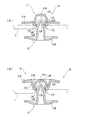
このタイプの従来のボタンとして、図4に示されるものがある。
図4(A)には、Fバーと称され多用されている一般形状のボタン本体50が示されており、このボタン本体50は、湾曲した凹部50Aが形成された係合部50Bと、この係合部50Bの開口端縁から大きく折り返して形成された折り返し部50Cと、この押し返し部50Cから外側に延出し、かつ、開口端側に向けて傾斜して形成されたフランジ部50Dとを備えている。
図4(B)には、Eバーと称され多用されている一般形状のボタン本体51が示されており、このボタン本体51は、略矩形状の凹部51Aが形成された中心部51Bと、この中心部51Bの開口端縁から少し折り返して形成された折り返し部51Cと、この折り返し部51Cから外側に真っ直ぐ延出して形成されたフランジ部51Dとを備えている。
図4(C)には、ボタン本体50,51と対となる止め具としてのシャンク式リベット52が示されており、このリベット52は、フランジ部52Aと、このフランジ部52Aの中央部に設けられた軸部52Bとを備え、この軸部52Bの先端部は鋭利に形成されている。図4(D)には、ボタン本体50,51と対となる止め具としてのヘッダー式リベット53が示されており、このリベット53は、フランジ部53Aと、このフランジ部53Aの中央部に設けられた軸部53Bとを備え、この軸部53Bの先端部は角部が切り欠かれて形成されている。
2. Description of the Related Art Conventionally, buttons that are attached with a cloth interposed between a button body and a stopper are known. This button has a structure including a button main body in which a concave portion is formed and a stopper through which the tip portion is inserted.
A conventional button of this type is shown in FIG.
FIG. 4A shows a
FIG. 4B shows a
FIG. 4 (C) shows a
図4で示される従来例では、ボタン本体50,51とリベット52,53との間に生地を介在させるが、生地を押さえるために、ボタン本体50,51の係合部50B,51Bは、その開口端部を形成する部分がフランジ部50D,51Dより突出して形成されている。そのため、ボタン本体50,51のフランジ部50D,51Dとリベット52,53のフランジ部52A,53Aとの間の空間が大きくなるので、薄手の生地での押えが十分に行えない。生地の押えが十分に行えないと、生地からボタン本体50,51やリベット52,53が外れる虞れがある他、生地とボタン本体50,51やリベット52,53との間に異物や人間の爪が入り込む虞れもある。
このような問題を解決するために、ボタン本体50,51の形状を変更せず、リベットのフランジ部を逆円錐状(お猪口形状)に形成することが考えられるが、フランジ部を逆円錐状に加工形成することは困難である。
In the conventional example shown in FIG. 4, the cloth is interposed between the
In order to solve such a problem, it is conceivable to form the flange portion of the rivet into an inverted conical shape (mouth shape) without changing the shape of the button
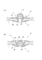
そのため、薄手の生地にボタンを取り付けるために、図5で示される特殊な形状のボタン本体と止め具とを備えたボタンの従来例がある。
図5(A)は、スタッドと称され凹部60Aが形成されるボタン本体60と、薄い板材から成形されるポストと称される止め具61とを備えたボタンを示す。
止め具61は、フランジ部61Aと、フランジ部61Aの中央部に形成された脚部61Bとを備え、この脚部61Bの先端に外側に向けて開く加工が施されたフレアー61Cが形成されている。このフレアー61Cとボタン本体60の凹部60Aとの間で生地を切断する。そのため、キャップ本体60の凹部60Aは、フレアー61Cとの間で生地を切断するために開口端縁が狭く奥にいくに従って広く形成される特殊形状とされている。
図5(B)は、Gバーと称されるボタン本体62と、ポストリベットと称される止め具63とを備えたボタンを示す。
ボタン本体62は、端縁が折り曲げて成形された正面部62Aと、この正面部62Aの端縁に外側縁が係止され内側に鋭利な切断縁62Cが形成された係止部62Bとを備えた特殊な形状である。止め具63は、フランジ部63Aと、このフランジ部63Aの中央に形成された脚部63Bとを備え、この脚部63Bは係止部62Bの切断縁との間で生地を切断するための傾斜部63Cを備えている。
Therefore, in order to attach a button to a thin fabric, there is a conventional example of a button including a button body and a stopper having a special shape shown in FIG.
FIG. 5 (A) shows a button including a
The
FIG. 5B shows a button including a button
The button
また、ボタンの従来例として、実願昭54-73456号(実開昭55-173907号)のマイクロフィルム(特許文献1)に記載されたものがある。
特許文献1のボタンは、円錐状突出部を有するボタン本体と、円錐状突出部に当接して先端部が折曲可能とされる係止部と、この係止部が中央部に取り付けられるフランジとを有する構造であり、係止部はボタン本体との間で生地を切断する刃状エッジが環状に複数配列して形成されている。
As a conventional example of a button, there is one described in a microfilm (Patent Document 1) of Japanese Utility Model Application No. 54-73456 (Japanese Utility Model Application Publication No. 55-173907).
The button of
図5で示される従来例では、ボタン本体の形状が特殊なため、この取付構造がFバーやEバー等の多用されたボタン本体にそのまま利用することができないという課題がある。
特に、図5(A)で示されるボタンでは、止め具61のフレアーと適合する凹部の形状が一義的に決定されるため、この止め具61に図4で示されるFバーやEバーのボタン本体を適用することはできない。
さらに、止め具61のフレアーは先端部が薄く形成されているため、デニム生地等の厚い生地に取り付ける場合には、フレアー先端とボタン本体の凹部との間でデニム生地を十分に切断することができない。無理に取り付けようとすると、フレアーの先端が変形して、より取付が困難となる。
特許文献1では、生地が厚手であったり、剛強であった場合には、刃状エッジが変形あるいは破損してしまうという課題がある。逆に、生地が薄手であったり、柔軟であった場合には、生地を押さえきれず、切断時に生地を巻き込み正しくボタンを生地に取り付けられないという課題がある。
In the conventional example shown in FIG. 5, since the shape of the button body is special, there is a problem that this mounting structure cannot be used as it is for a frequently used button body such as an F bar or an E bar.
In particular, in the button shown in FIG. 5A, since the shape of the concave portion that matches the flare of the
Further, since the flare of the
In
本発明の目的は、多用されている一般形状のボタン本体を用いて生地の厚さや硬さにかかわらず生地に取り付けることができるボタンを提供することにある。 An object of the present invention is to provide a button that can be attached to a cloth regardless of the thickness or hardness of the cloth using a button body of a general shape that is frequently used.
本発明のボタンは、ボタン本体と止め具とを備え、前記ボタン本体との間に生地を介在させて前記止め具を押圧固定するボタンであって、前記ボタン本体には前記止め具の先端部を挿通する収納部が形成され、前記止め具は、前記先端部と、この先端部から連続して形成された筒状部との間に肩部が形成され、この肩部は、前記ボタン本体の収納部の挿通端との間で前記生地を切断する切断部を備えたことを特徴とする。 The button of the present invention is a button that includes a button main body and a stopper, and presses and fixes the stopper with a cloth interposed between the button main body, and the button main body includes a distal end portion of the stopper. The stopper is formed with a shoulder portion between the tip portion and a cylindrical portion formed continuously from the tip portion, and the shoulder portion is formed of the button body. The cutting part which cut | disconnects the said cloth | dough between the insertion ends of the storage part of this is provided, It is characterized by the above-mentioned.
この発明によれば、ボタン本体と止め具との間に生地を挟んだ状態で互いに押し付けると、止め具の先端部で生地を押さえながら肩部に形成された切断部とボタン本体の収納部の挿通端との間で生地が切断されてボタンが取り付けられる。
そのため、本発明では、止め具の肩部に形成された切断部とボタン本体の収納部の挿通端との間で生地を切断する。肩部は、その板厚が従来例で示されるフレアーやエッジに比べて薄くしなくてもよいから、たとえ切断部に大きな力が集中しても、破損するという不都合が無く、その上、調芯性も劣化することがない。そのため、本発明では、厚手の生地でも薄手の生地でも止め具を破損することなく容易に切断することができる。さらに、本発明では、ボタン本体は、収納部が形成される形状であるため、FバーやEバー等と同様の一般形状を採用することで、多用されるボタン本体をそのまま利用することができる。
According to the present invention, when the fabric is pressed between the button main body and the stopper, the cutting portion formed on the shoulder and the storage portion of the button main body are pressed while pressing the fabric at the distal end of the stopper. The cloth is cut between the insertion end and the button is attached.
Therefore, in this invention, cloth | dough is cut | disconnected between the cutting part formed in the shoulder part of a stopper, and the insertion end of the accommodating part of a button main body. Since the thickness of the shoulder portion does not have to be thinner than the flare or edge shown in the conventional example, there is no inconvenience that it breaks even if a large force is concentrated on the cut portion. The core property is not deteriorated. Therefore, in the present invention, it is possible to easily cut a thick or thin fabric without damaging the stopper. Furthermore, in the present invention, since the button main body has a shape in which the storage portion is formed, the button main body that is frequently used can be used as it is by adopting the same general shape as the F bar and E bar. .
本発明では、前記切断部は前記肩部に形成された角部である構成が好ましい。ここにおいて、前記角部の曲率半径Rは、0.5mm以下であり、好ましくは、0.3mm以下である。
この発明では、切断部は先端部と筒状部との間に形成された角部に形成されることで、切断部の加工が容易となり、止め具の製造を容易に行うことができる。
In the present invention, the cutting part is preferably a corner formed on the shoulder. Here, the radius of curvature R of the corner is 0.5 mm or less, preferably 0.3 mm or less.
In this invention, since the cutting part is formed at the corner formed between the tip part and the cylindrical part, the cutting part can be easily processed, and the fastener can be easily manufactured.
また、本発明では、前記切断部は、前記肩部の円周上に連続的又は断続的に形成されていることが好ましい。
この発明では、収納部の挿通端に沿って生地も適切かつ容易に切断することができる。
さらに、前記肩部は、その外周部が前記筒状部より径方向に膨出して形成されている構成が好ましい。
この発明では、肩部の変形がしにくくなり、切断部の破損をより効果的に防止することができる。
Moreover, in this invention, it is preferable that the said cutting part is formed continuously or intermittently on the circumference of the said shoulder part.
In the present invention, the fabric can be appropriately and easily cut along the insertion end of the storage portion.
Furthermore, it is preferable that the shoulder portion is formed such that an outer peripheral portion bulges in a radial direction from the cylindrical portion.
In this invention, it becomes difficult to deform the shoulder portion, and breakage of the cut portion can be more effectively prevented.
また、前記先端部は前記肩部から突出する突出部を備えている構成が好ましい。
この発明では、止め具の切断部とボタン本体の収納部の挿通端との間で生地を切断するにあたり、肩部から突出する突出部が生地を押し引っ張っているため、生地の切断が容易になり、切断部を破損することなく円滑に生地の切断を行える。
Moreover, the structure which the said front-end | tip part is provided with the protrusion part which protrudes from the said shoulder part is preferable.
In this invention, when cutting the fabric between the cutting portion of the stopper and the insertion end of the storage portion of the button body, the protruding portion protruding from the shoulder pushes and pulls the fabric, so that the fabric can be easily cut. Thus, the fabric can be cut smoothly without damaging the cut portion.
さらに、前記先端部は、前記ボタン本体で押圧された際に没入して側方に膨出可能とされるとともに、膨張した先端部が前記収納部に係止される構成が好ましい。
この発明では、ボタンを取り付けるにあたり、ボタン本体で押圧された先端部は没入されて側方に膨出することで、先端部の側部がボタン本体の収納部の側面を十分に押圧するので、ボタンの取り外し力(セパレーション力)が向上することになる。そのため、ボタン本体が止め具から誤って外れることがなくなる。
さらに、止め具のフランジ部を薄手の生地を押さえ易い板状形状にすれば、板材から加工しても、本発明の切断部である角部12Fさらには突出部12Eを設けることが可能であり、生地の切断を容易に行える。止め具の材料となる板材の板厚は、0.2mm〜
1mmが好ましく、さらには、0.3mm〜0.6mmが好ましい。
Furthermore, it is preferable that the distal end portion is immersed and bulged laterally when pressed by the button body, and the expanded distal end portion is locked to the storage portion.
In this invention, when attaching the button, the tip portion pressed by the button body is immersed and bulges sideways, so that the side portion of the tip portion sufficiently presses the side surface of the storage portion of the button body, The removal force (separation force) of the button will be improved. Therefore, the button body is not accidentally detached from the stopper.
Furthermore, if the flange portion of the stopper is formed into a plate shape that can easily hold the thin fabric, it is possible to provide the
1 mm is preferable, and 0.3 mm to 0.6 mm is more preferable.
以下、本発明の実施形態を図面に基づいて説明する。本実施形態はジーンズその他の被服において飾りボタンとして適用されたものである。
図1(A)は第1実施形態を示す断面図である。
図1(A)において、ボタン10は、間に生地1を介在させて互いに取り付けられるボタン本体11と止め具12とを備えて構成されている。
ボタン本体11は、図4(B)で示されるボタン本体と同じ構造であり、Fバーと称される。このボタン本体11は、アルミニウム、鉄、ステンレス合金・真鍮を含む銅合金、その他の金属又は合金からプレス等の適宜な加工手段により形成されるものである。
ボタン本体11は、収納部としての凹部11Aが形成された中心部11Bと、この中心部11Bの挿通端である開口端の縁から少し折り返して形成された折り返し部11Cと、この折り返し部11Cから外側に真っ直ぐ延出して形成されたフランジ部11Dとが一体に形成された構造である。
中心部11Bは有底円筒状に形成されており、その内面が凹部11Aとされる。この凹部11Aは、略矩形状に形成されており、その開口端11Eは適宜な曲率の丸みが形成されている。
折り返し部11Cは、中心部11Bから反転して形成されており、その端部からフランジ部11Dが略直角に形成されている。フランジ部11Dは略幅広のリング状に形成されている。
Hereinafter, embodiments of the present invention will be described with reference to the drawings. This embodiment is applied as a decorative button in jeans or other clothing.
FIG. 1A is a cross-sectional view showing the first embodiment.
In FIG. 1A, a
The button
The
The
The folded
止め具12は、ボタン本体11と同様に、アルミニウム、鉄、ステンレス合金・真鍮を含む銅合金、その他の金属又は合金からプレス等の適宜な加工手段により形成されるものである。
止め具12は、凹部11Aに挿通される略円盤状の先端部12Aと、この先端部12Aから連続して形成された略円筒状の筒状部12Bと、先端部12Aと筒状部12Bとの間に形成された肩部12Cと、前記筒状部12Bの端部に連続形成された略幅広リング状のフランジ部12Dとが一体に形成された構造である。
先端部12Aは、その中心部に凹部11A側に向けて突出する有底円筒状の突出部12Eを備えている。この突出部12Eは、ボタン本体11で押圧された際に没入することを可能とされている。止め具12は、いわば、リベットとして機能するため、突出部12Eが先端部12Aの平面部より没入すると、先端部12A全体が側方に膨出し、この膨張した先端部12Eが凹部11Aの側面を押圧して係止される(図2(A)参照)。
Similarly to the button
The
The
フランジ部12Dは、その外周縁に向うに従ってボタン本体11側に向くように傾斜して形成されている。
肩部12Cは、その円周上に連続して外周縁部に角部12Fが形成され、この角部12Fはボタン本体11の凹部11Aの開口端11Eとの間で生地1を切断する切断部とされている。ここで、角部12Fは、その曲率半径Rが0.5mm以下であり、好ましくは、0.3mm以下である。前記曲率半径Rは小さければ小さい程好ましいが、本実施形態では、0.3mm〜0.2mmである。また、角部12Fの外径寸法は凹部11Aの開口端11Eの内径寸法と同じかやや小さく形成されている。
肩部12Eは、その外周部が筒状部12Bより径方向に膨出して形成されている。
The
The
The
この構成の第1実施形態のボタン10を生地1に取り付けるため、ボタン本体11と止め具12との間に生地1を挟み、止め具12の先端部12Aをボタン本体11の凹部11Aに挿通させるように押し付ける。
すると、止め具12の先端部12Aの突出部12Eで生地1を押し引っ張りながら肩部12Cに形成された角部12Fとボタン本体11の凹部11Aの開口端11Eとの間で生地1が切断される。
さらに、先端部12Aを凹部11Aに向けて押し付けると、図2(A)に示される通り、突出部12Eが先端部12Aの平面部より没入することになり、これにより、先端部12E及び筒状部12B全体が側方に膨出して凹部11Aの側面に押圧係止される。
In order to attach the
Then, the
Further, when the
従って、第1実施形態では、次の作用効果を奏することができる。
(1)ボタン本体11には止め具12の先端部12Aを挿通する凹部11Aが形成され、止め具12は、先端部12Aと、この先端部12Aから連続して形成された筒状部12Bとの間に肩部12Cが形成され、この肩部12Cは、ボタン本体11の凹部11Aの開口端11Eとの間で生地1を切断する切断部である角部12Fを備えているから、角部12Fに大きな力がかかっても、肩部12Cの板厚は厚いので、肩部12Cが破損せず、厚手の生地でも薄手の生地でも容易に切断することができる。さらに、ボタン本体11は、凹部11Aが形成される形状であるため、Fバータイプのものをそのまま用いることができる。
Therefore, in the first embodiment, the following operational effects can be achieved.
(1) The
(2)切断部は肩部12Cに形成された角部12Fであるため、切断部の加工が容易となり、止め具の製造を容易に行うことができる。
(3)肩部12Cは、その外周部が筒状部12Bより径方向に膨出して形成されているため、肩部12Cの変形がしにくくなり、止め具12の破損をより効果的に防止することができる。
(2) Since the cutting portion is the
(3) Since the outer peripheral portion of the
(4)先端部12Aは肩部12Cから突出する突出部12Eを備えているから、止め具12の角部12Fとボタン本体11の凹部11Aの開口端11Eとの間で生地1を切断するにあたり、肩部12Cから突出する突出部12Eが生地1を押し引っ張っているため、生地の切断が容易となり、切断部である角部12Fを破損することなく円滑に生地1の切断を行える。
(5)突出部12Eは、ボタン本体11に向けて押圧した際に没入して先端部12Aが側方に膨出可能とされるとともに、膨張した先端部12Aが凹部11Aに係止される構成としたので、ボタンを取り付けるにあたり、先端部12Aの側部がボタン本体11の凹部11Aの側面を十分に押圧するので、ボタンの取り外し力(セパレーション力)が向上することになる。そのため、ボタン本体11が止め具12から誤って外れることがなくなる。
(6)止め具のフランジ部を、薄手の生地を押さえ易い板状形状にするため、板材から加工しても、切断部である角部12Fさらには突出部12Eを設けることが可能であり、生地の切断を容易に行える。止め具の材料となる板材の板厚は、0.2mm〜1mmが好ましく、さらには、0.3mm〜0.6mmが好ましい。
(4) Since the
(5) The protruding
(6) In order to make the flange portion of the stopper into a plate-like shape that can easily hold a thin fabric, it is possible to provide a
次に、本発明の第2実施形態を説明する。第2実施形態はボタン本体の構造が相違するのみで、止め具の構造は第1実施形態の止め具12と同じ構造である。ここで、第2実施形態の説明中、第1実施形態と同一構成部材は同一符号を付して説明を省略する。
本実施形態は飾りボタンに適用されたものである。
図1(B)は第2実施形態を示す断面図である。
図1(B)において、ボタン20は、間に生地1を介在させて互いに取り付けられるボタン本体21と止め具12とを備えて構成されている。
Next, a second embodiment of the present invention will be described. The second embodiment is different only in the structure of the button body, and the structure of the stopper is the same as that of the
This embodiment is applied to a decorative button.
FIG. 1B is a cross-sectional view showing the second embodiment.
1B, the
ボタン本体21は、図4(A)で示されるボタン本体と同じ構造であり、Fバーと称される。このボタン本体21は、第1実施形態のボタン本体11と同様に、アルミニウム、鉄、ステンレス合金・真鍮を含む銅合金、その他の金属又は合金からプレス等の適宜な加工手段により形成されるもので、収納部としての凹部21Aが形成された中心部21Bと、この中心部21Bの開口端縁から少し折り返して形成された折り返し部21Cと、この折り返し部21Cから外側に延出して形成されたフランジ部21Dとが一体に形成された構造である。
中心部21Bは有底円筒状に形成されており、その内面が凹部21Aとされる。この凹部21Aは、湾曲して形成されており、その開口端21Eは適宜な曲率の丸みが形成されている。
折り返し部21Cは、中心部21Aから反転して中心部21Aの頂部近傍まで延びて形成されており、その端部からフランジ部21Dが略直角に形成されている。フランジ部21Dは略幅広のリング状に形成されている。
The
The
The folded
この構成の第2実施形態のボタン20を生地1に取り付けるため、第1実施形態と同様に、ボタン本体21と止め具12との間に生地1を挟み、止め具12の先端部12Aをボタン本体21の凹部21Aに挿通させるように押し付ける。
すると、止め具12の先端部12Aの突出部12Eで生地1を押し引っ張りながら肩部12Cに形成された角部12Fとボタン本体21の凹部21Aの開口端21Eとの間で生地1が切断される。
さらに、先端部12Aを凹部21Aに向けて押し付けると、図2(B)に示される通り、突出部12Eが先端部12Aの平面部より没入することになり、これにより、先端部12E全体が側方に膨出して凹部21Aの側面に押圧係止される。
従って、第2実施形態では、第1実施形態の(1)〜(6)と同様の作用効果を奏することができる。
In order to attach the
Then, the
Further, when the
Therefore, in 2nd Embodiment, there can exist the same effect as (1)-(6) of 1st Embodiment.
なお、本発明は前述の実施形態に限定されるものではなく、本発明の目的を達成できる範囲での変形、改良等は本発明に含まれるものである。
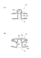
例えば、前記第2実施形態では、収納部を凹部21Aとし、挿通端を開口端21Eとしたが、収納部や挿通端の構造は前記実施形態に限定されるものではない。例えば、図3(A)に示される通り、ボタン本体21の収納部を、頂部に開口部21Gが形成された形状としてもよい。この場合、挿通端21Hは、開口部21Gとは反対側の開口部となる。なお、符号30はボタン取付工具である。さらに、本発明では、図3(B)に示される通り、止め具12のフランジ部12Dにシェル12Gを取り付ける構造としてもよい。
It should be noted that the present invention is not limited to the above-described embodiments, and modifications, improvements, and the like within the scope that can achieve the object of the present invention are included in the present invention.
For example, in the second embodiment, the storage portion is the
また、前記実施形態では、飾りボタンに適用した例を説明したが、本発明では、衣服の合わせ目を止めるものであって、主に実用性を目的としたボタンに適用してもよい。さらに、衣服以外にも本発明のボタンを用いてもよい。
また、本発明では、筒状部12Bは円筒状に形成する他、角筒状に形成するものでもよい。
さらに、切断部は、肩部12Cの円周上に連続的に形成されるものに限定されるものではなく、断続的に形成するものでもよい。この場合、生地1にミシン目を入れて切断部を生地1に押圧することで、生地1を切断することができる。
Moreover, although the example applied to the decoration button was demonstrated in the said embodiment, in this invention, it may stop the joint of clothing and may apply to the button mainly aimed at practicality. Furthermore, you may use the button of this invention besides clothes.
In the present invention, the
Furthermore, the cutting portion is not limited to the one continuously formed on the circumference of the
本発明はジーンズ等の被服、さらには、被服以外のもの一般に利用することができる。 The present invention can be used for clothes such as jeans, and generally for clothes other than clothes.
1…生地、10…ボタン、11…ボタン本体、11A…凹部(収納部)、11E…開口端(挿通端)、12…止め具、12A…先端部、12B…筒状部、12C…肩部、12E…突出部、12F…角部(切断部)、20…ボタン、21…ボタン本体、21A…凹部(収納部)、21E…開口端(挿通端)
DESCRIPTION OF
Claims (6)
前記ボタン本体11,21には前記止め具12の先端部12Aを挿通する収納部11A,21Aが形成され、前記止め具12は、前記先端部12Aと、この先端部12Aから連続して形成された筒状部12Bとの間に肩部12Cが形成され、この肩部12Cは、前記ボタン本体11,21の収納部11A,21Aの挿通端11E,21Eとの間で前記生地1を切断する切断部を備えたことを特徴とするボタン。 A button that includes button bodies 11 and 21 and a stopper 12, and presses and fixes the stopper 12 with the cloth 1 interposed between the button bodies 11 and 21;
The button bodies 11 and 21 are formed with storage portions 11A and 21A through which the distal end portion 12A of the stopper 12 is inserted, and the stopper 12 is formed continuously from the distal end portion 12A and the distal end portion 12A. A shoulder portion 12C is formed between the cylindrical portion 12B, and the shoulder portion 12C cuts the cloth 1 between the insertion portions 11E and 21E of the storage portions 11A and 21A of the button bodies 11 and 21. A button characterized by having a cutting part.
Priority Applications (7)
| Application Number | Priority Date | Filing Date | Title |
|---|---|---|---|
| JP2004014499A JP2005204911A (en) | 2004-01-22 | 2004-01-22 | Button |
| US11/038,962 US20050160562A1 (en) | 2004-01-22 | 2005-01-20 | Button |
| DE602005016475T DE602005016475D1 (en) | 2004-01-22 | 2005-01-21 | stud |
| BR0500193-5A BRPI0500193A (en) | 2004-01-22 | 2005-01-21 | Button |
| CN200510005616.9A CN1644126B (en) | 2004-01-22 | 2005-01-21 | Button |
| EP05250299A EP1557107B1 (en) | 2004-01-22 | 2005-01-21 | Button |
| ES05250299T ES2331137T3 (en) | 2004-01-22 | 2005-01-21 | BUTTON. |
Applications Claiming Priority (1)
| Application Number | Priority Date | Filing Date | Title |
|---|---|---|---|
| JP2004014499A JP2005204911A (en) | 2004-01-22 | 2004-01-22 | Button |
Publications (2)
| Publication Number | Publication Date |
|---|---|
| JP2005204911A true JP2005204911A (en) | 2005-08-04 |
| JP2005204911A5 JP2005204911A5 (en) | 2007-03-15 |
Family
ID=34631931
Family Applications (1)
| Application Number | Title | Priority Date | Filing Date |
|---|---|---|---|
| JP2004014499A Pending JP2005204911A (en) | 2004-01-22 | 2004-01-22 | Button |
Country Status (7)
| Country | Link |
|---|---|
| US (1) | US20050160562A1 (en) |
| EP (1) | EP1557107B1 (en) |
| JP (1) | JP2005204911A (en) |
| CN (1) | CN1644126B (en) |
| BR (1) | BRPI0500193A (en) |
| DE (1) | DE602005016475D1 (en) |
| ES (1) | ES2331137T3 (en) |
Cited By (4)
| Publication number | Priority date | Publication date | Assignee | Title |
|---|---|---|---|---|
| WO2011074053A1 (en) | 2009-12-14 | 2011-06-23 | Ykk株式会社 | Button fastener and button structure |
| WO2013042232A1 (en) * | 2011-09-21 | 2013-03-28 | Ykk株式会社 | Button body and button |
| JPWO2013042232A1 (en) * | 2011-09-21 | 2015-03-26 | Ykk株式会社 | Button body and button |
| WO2016038666A1 (en) * | 2014-09-08 | 2016-03-17 | Ykk株式会社 | Rivet |
Families Citing this family (10)
| Publication number | Priority date | Publication date | Assignee | Title |
|---|---|---|---|---|
| JP4554657B2 (en) * | 2007-10-01 | 2010-09-29 | Ykk株式会社 | button |
| BRPI0922442A2 (en) * | 2008-12-11 | 2015-08-04 | Syngenta Participations Ag | Sugar cane transformation. |
| US20100175226A1 (en) * | 2009-01-12 | 2010-07-15 | Foo-Yuen Wong | Two-component tack button |
| US9049904B2 (en) | 2010-02-26 | 2015-06-09 | Ykk Corporation | Button fastener, method for forming button fastener, eyelet, and method for forming eyelet |
| CN102318935A (en) * | 2011-07-22 | 2012-01-18 | 关伟成 | Metal button pedestal and manufacturing technology thereof |
| JP5731655B2 (en) * | 2011-09-02 | 2015-06-10 | Ykk株式会社 | Enclosure, fastener, button, and fixing method for fixing object |
| JP5447492B2 (en) * | 2011-11-25 | 2014-03-19 | トヨタ自動車株式会社 | Sealed battery |
| CN110025088B (en) * | 2019-04-12 | 2021-12-03 | 深圳市松记钮扣制品有限公司 | Fastener for button universal for thin and thick cloth |
| US10983600B2 (en) * | 2019-08-13 | 2021-04-20 | Apple Inc. | Electronic devices with fabric buttons |
| TWI781403B (en) * | 2020-05-14 | 2022-10-21 | 美宸科技股份有限公司 | Fabric strain gauge, fabric pressure gauge, and smart clothing |
Family Cites Families (11)
| Publication number | Priority date | Publication date | Assignee | Title |
|---|---|---|---|---|
| US576759A (en) * | 1897-02-09 | Theophilus r | ||
| US631212A (en) * | 1897-11-05 | 1899-08-15 | Rudolph Hoermann | Button. |
| FR1102092A (en) * | 1954-03-29 | 1955-10-17 | Successeurs De Bois & Chassand | Improvements to riveted buttons for fabrics and others |
| GB1491617A (en) * | 1975-07-04 | 1977-11-09 | Bengtsson Sigurd W | Fitting for example a button including a male and a female portion |
| DE7935319U1 (en) * | 1979-12-15 | 1980-03-20 | Schaeffer-Homberg Gmbh, 5600 Wuppertal | RIVET CAP |
| JPS5925208U (en) * | 1982-08-11 | 1984-02-16 | 日本ノ−シヨン工業株式会社 | clothing button |
| AU557267B2 (en) * | 1983-04-13 | 1986-12-18 | Nippon Notion Kogyo Co. Ltd. | Button |
| FR2553268B1 (en) * | 1983-10-13 | 1985-12-27 | Stocko France Sa | AUTOMATIC BUTTON IN PARTICULAR NAIL BUTTON |
| DE3717287A1 (en) * | 1987-05-22 | 1988-12-01 | Prym Werke William | RIVETABLE HARD HARDWARE ITEM, LIKE PUSH BUTTON, CONSISTING OF A RIVETING PART WITH A TUBULAR RIVET |
| CN2364717Y (en) * | 1999-01-22 | 2000-02-23 | 力顿钮扣配件(深圳)有限公司 | Plastic-steel snap-fastener fastening structure |
| JP2001178505A (en) * | 1999-12-24 | 2001-07-03 | Ykk Corp | Tack for button |
-
2004
- 2004-01-22 JP JP2004014499A patent/JP2005204911A/en active Pending
-
2005
- 2005-01-20 US US11/038,962 patent/US20050160562A1/en not_active Abandoned
- 2005-01-21 ES ES05250299T patent/ES2331137T3/en active Active
- 2005-01-21 EP EP05250299A patent/EP1557107B1/en not_active Expired - Fee Related
- 2005-01-21 BR BR0500193-5A patent/BRPI0500193A/en not_active IP Right Cessation
- 2005-01-21 DE DE602005016475T patent/DE602005016475D1/en active Active
- 2005-01-21 CN CN200510005616.9A patent/CN1644126B/en not_active Expired - Fee Related
Cited By (6)
| Publication number | Priority date | Publication date | Assignee | Title |
|---|---|---|---|---|
| WO2011074053A1 (en) | 2009-12-14 | 2011-06-23 | Ykk株式会社 | Button fastener and button structure |
| WO2013042232A1 (en) * | 2011-09-21 | 2013-03-28 | Ykk株式会社 | Button body and button |
| JPWO2013042232A1 (en) * | 2011-09-21 | 2015-03-26 | Ykk株式会社 | Button body and button |
| WO2016038666A1 (en) * | 2014-09-08 | 2016-03-17 | Ykk株式会社 | Rivet |
| JPWO2016038666A1 (en) * | 2014-09-08 | 2017-04-27 | Ykk株式会社 | rivet |
| US9872540B2 (en) | 2014-09-08 | 2018-01-23 | Ykk Corporation | Rivet |
Also Published As
| Publication number | Publication date |
|---|---|
| EP1557107B1 (en) | 2009-09-09 |
| DE602005016475D1 (en) | 2009-10-22 |
| BRPI0500193A (en) | 2005-09-06 |
| ES2331137T3 (en) | 2009-12-22 |
| EP1557107A1 (en) | 2005-07-27 |
| US20050160562A1 (en) | 2005-07-28 |
| CN1644126A (en) | 2005-07-27 |
| CN1644126B (en) | 2010-05-05 |
Similar Documents
| Publication | Publication Date | Title |
|---|---|---|
| EP1557107B1 (en) | Button | |
| US20120246881A1 (en) | Button Fastener and Button Structure | |
| TWI273951B (en) | Retaining device | |
| JP2006068388A (en) | Stud and button | |
| JPWO2011086674A1 (en) | Button mounting member and button | |
| JP2007151526A (en) | Correcting element and device of squid fishing hook | |
| JP3131875U (en) | Hatome | |
| US3320644A (en) | Tack-fastened button | |
| JP4171409B2 (en) | button | |
| JP2000270906A (en) | Snap button directional in unsticking | |
| JP2008128313A (en) | Peel type blind rivet | |
| JP2613644B2 (en) | Core drill | |
| JP2006288993A (en) | Triangular button | |
| KR200402100Y1 (en) | Blind rivet | |
| US1246163A (en) | Collar-button. | |
| JP3120864U (en) | Mounting structure for gripping part in pan | |
| JP2005348796A (en) | Clasp for adornment | |
| US1899680A (en) | Button | |
| JP6342962B2 (en) | scissors | |
| JP3202240U (en) | Hatome | |
| JP2005081743A (en) | Clip fitting structure | |
| JPH0852013A (en) | Pierced earring | |
| JP5286533B2 (en) | Mounting member holder | |
| JP3206229U (en) | Buckle for wristband leather band | |
| JPH08256810A (en) | Fastener for necklace, etc. |
Legal Events
| Date | Code | Title | Description |
|---|---|---|---|
| A621 | Written request for application examination |
Free format text: JAPANESE INTERMEDIATE CODE: A621 Effective date: 20070122 |
|
| A521 | Request for written amendment filed |
Free format text: JAPANESE INTERMEDIATE CODE: A523 Effective date: 20070129 |
|
| RD02 | Notification of acceptance of power of attorney |
Free format text: JAPANESE INTERMEDIATE CODE: A7422 Effective date: 20070703 |
|
| RD02 | Notification of acceptance of power of attorney |
Free format text: JAPANESE INTERMEDIATE CODE: A7422 Effective date: 20070815 |
|
| A977 | Report on retrieval |
Free format text: JAPANESE INTERMEDIATE CODE: A971007 Effective date: 20090807 |
|
| A131 | Notification of reasons for refusal |
Free format text: JAPANESE INTERMEDIATE CODE: A131 Effective date: 20090825 |
|
| A02 | Decision of refusal |
Free format text: JAPANESE INTERMEDIATE CODE: A02 Effective date: 20100105 |