JP2005202014A - Audio signal processor, audio signal processing method, and audio signal processing program - Google Patents
Audio signal processor, audio signal processing method, and audio signal processing program Download PDFInfo
- Publication number
- JP2005202014A JP2005202014A JP2004006456A JP2004006456A JP2005202014A JP 2005202014 A JP2005202014 A JP 2005202014A JP 2004006456 A JP2004006456 A JP 2004006456A JP 2004006456 A JP2004006456 A JP 2004006456A JP 2005202014 A JP2005202014 A JP 2005202014A
- Authority
- JP
- Japan
- Prior art keywords
- speaker
- audio signal
- information
- change point
- signal processing
- Prior art date
- Legal status (The legal status is an assumption and is not a legal conclusion. Google has not performed a legal analysis and makes no representation as to the accuracy of the status listed.)
- Pending
Links
Images


Classifications
-
- G—PHYSICS
- G11—INFORMATION STORAGE
- G11B—INFORMATION STORAGE BASED ON RELATIVE MOVEMENT BETWEEN RECORD CARRIER AND TRANSDUCER
- G11B27/00—Editing; Indexing; Addressing; Timing or synchronising; Monitoring; Measuring tape travel
- G11B27/02—Editing, e.g. varying the order of information signals recorded on, or reproduced from, record carriers
- G11B27/031—Electronic editing of digitised analogue information signals, e.g. audio or video signals
- G11B27/034—Electronic editing of digitised analogue information signals, e.g. audio or video signals on discs
-
- B—PERFORMING OPERATIONS; TRANSPORTING
- B41—PRINTING; LINING MACHINES; TYPEWRITERS; STAMPS
- B41F—PRINTING MACHINES OR PRESSES
- B41F16/00—Transfer printing apparatus
-
- G—PHYSICS
- G11—INFORMATION STORAGE
- G11B—INFORMATION STORAGE BASED ON RELATIVE MOVEMENT BETWEEN RECORD CARRIER AND TRANSDUCER
- G11B20/00—Signal processing not specific to the method of recording or reproducing; Circuits therefor
- G11B20/00007—Time or data compression or expansion
-
- G—PHYSICS
- G11—INFORMATION STORAGE
- G11B—INFORMATION STORAGE BASED ON RELATIVE MOVEMENT BETWEEN RECORD CARRIER AND TRANSDUCER
- G11B20/00—Signal processing not specific to the method of recording or reproducing; Circuits therefor
- G11B20/10—Digital recording or reproducing
-
- G—PHYSICS
- G11—INFORMATION STORAGE
- G11B—INFORMATION STORAGE BASED ON RELATIVE MOVEMENT BETWEEN RECORD CARRIER AND TRANSDUCER
- G11B20/00—Signal processing not specific to the method of recording or reproducing; Circuits therefor
- G11B20/10—Digital recording or reproducing
- G11B20/10527—Audio or video recording; Data buffering arrangements
-
- B—PERFORMING OPERATIONS; TRANSPORTING
- B41—PRINTING; LINING MACHINES; TYPEWRITERS; STAMPS
- B41F—PRINTING MACHINES OR PRESSES
- B41F19/00—Apparatus or machines for carrying out printing operations combined with other operations
-
- G—PHYSICS
- G11—INFORMATION STORAGE
- G11B—INFORMATION STORAGE BASED ON RELATIVE MOVEMENT BETWEEN RECORD CARRIER AND TRANSDUCER
- G11B20/00—Signal processing not specific to the method of recording or reproducing; Circuits therefor
- G11B20/00007—Time or data compression or expansion
- G11B2020/00014—Time or data compression or expansion the compressed signal being an audio signal
-
- G—PHYSICS
- G11—INFORMATION STORAGE
- G11B—INFORMATION STORAGE BASED ON RELATIVE MOVEMENT BETWEEN RECORD CARRIER AND TRANSDUCER
- G11B20/00—Signal processing not specific to the method of recording or reproducing; Circuits therefor
- G11B20/10—Digital recording or reproducing
- G11B20/10527—Audio or video recording; Data buffering arrangements
- G11B2020/10537—Audio or video recording
- G11B2020/10546—Audio or video recording specifically adapted for audio data
Abstract
Description
この発明は、例えば、IC(Integrated Circuit)レコーダ、MD(Mini Disc)レコーダ、パーソナルコンピュータなどの音声信号を処理する種々の装置、この装置で用いられる方法、プログラムに関する。 The present invention relates to various apparatuses for processing audio signals such as an IC (Integrated Circuit) recorder, an MD (Mini Disc) recorder, and a personal computer, and a method and a program used in the apparatus.
例えば、後に記す特許文献1に開示されているように、録音された音声データの音声認識を行って、これをテキストデータに変換し、自動的に議事録を作成するようにする議事録作成装置が提案されている。このような技術を用いることによって、人手を介すことなく、会議の議事録を迅速に作成することが可能となる。しかし、録音した全ての音声データに基づいた議事録を作成するまでもなく、重要な部分のみの議事録を作成するようにしたい場合もある。このため、録音した音声データから目的とする部分を探し出す必要が生じる。
For example, as disclosed in
例えば、ICレコーダやMDレコーダなどを用いて長時間の会議などの様子を録音した場合、記録された音声データから聞きたい場所を探し出すには、その音声データを再生し、再生音声を聴取するようにしなければならない。もちろん、早送りや早戻しなどの機能を用いて、目的とする部分を探すようにすることも可能であるが、手間や時間がかかる場合が多い。このため、「検索を容易にするための目印」をデータを録音したデータに埋め込むようにする(付加するようにする)ことができるようにした機能を備えた録音装置が提供されている。例えば、MDレコーダなどにおいては、トラックマークを付加する機能として実現されている。
ところが、上述したように、「検索を容易にするための目印」をデータに付加するようにする機能は、ユーザの手動操作により用いることができるものであり、ユーザの操作が無ければ、目印を付加することができない。したがって、録音中に重要であると判断した部分に目印を付す操作を行おうと思っていても、会議に集中している場合などにおいては、目印を付すための操作を忘れてしまう場合もあると考えられる。 However, as described above, the function of adding “a mark for easy search” to data can be used by a user's manual operation. If there is no user's operation, the mark is added. Cannot be added. Therefore, even if you want to mark an important part during recording, you might forget the mark-marking operation if you are concentrating on a meeting. Conceivable.
また、注目すべき発言部分に目印を付けられたとしても、目印を埋め込む操作は注目すべき発言を聞いたときに行われるので、目印は注目の発言の後ろに記録される。そのため、ユーザが注目の発言を聞くには、再生位置を目印のところに移動させたあと、少し前に戻す操作をしなければならない。希望の場所の先に進み過ぎたり、戻り過ぎたりして、この操作を繰り返さなければならないのは、ユーザにとってとても面倒でありストレスのたまる作業である。 Further, even if a mark is added to a noticeable speech part, the mark embedding operation is performed when a noteworthy comment is heard, so that the mark is recorded after the noticeable comment. Therefore, in order for the user to listen to the remarks of interest, the user has to move the playback position to the mark and then move it back a little. It is a very cumbersome and stressful operation for the user to repeat this operation by going too far beyond the desired place or returning too much.
また、目印がついている場所がどんな内容であるかは聞いてみるまで分からない。聞いてみて目的の場所でなければ、次の目印へと移動させる操作を目的の場所に達するまで繰り返さなければならず、これもまた手間のかかる作業である。このように、「検索を容易にするための目印」をデータに付加するようにする機能は、便利なものであるが、ユーザの操作がおぼつかない場合などにおいては、音声データの目的とする部分に目印を付す機能を十分に機能させることができない。 Also, I don't know until I ask what the place is marked with. If it is not the target location after listening, the operation of moving to the next landmark must be repeated until the target location is reached, which is also a time-consuming work. As described above, the function of adding “a mark for facilitating search” to the data is convenient. However, in the case where the user's operation is unclear, it is possible to add to the target portion of the audio data. The function of attaching a mark cannot be sufficiently functioned.
以上のことにかんがみ、この発明は、ユーザの手を煩わせることなく、処理対象の音声信号中の目的とする部分を迅速に見つけ出して利用することができるようにする装置、方法、プログラムを提供することを目的とする。 In view of the above, the present invention provides an apparatus, method, and program that can quickly find and use a target portion in an audio signal to be processed without bothering the user. The purpose is to do.
上記課題を解決するため、請求項1に記載の発明の音声信号処理装置は、
処理対象の音声信号に基づいて、当該音声信号の話者の変化を所定の処理単位毎に検出する検出手段と、
前記検出手段により話者が変化したと検出された前記音声信号上の位置を示す変化点情報を取得する取得手段と、
前記取得手段により取得された前記変化点情報を保持する保持手段と
を備えることを特徴とする。
In order to solve the above-described problem, an audio signal processing device according to
Detecting means for detecting, for each predetermined processing unit, a change in speaker of the audio signal based on the audio signal to be processed;
Acquisition means for acquiring change point information indicating a position on the audio signal detected by the detection means as a speaker has changed;
Holding means for holding the change point information acquired by the acquisition means.
この請求項1に記載の発明の音声信号処理装置は、検出手段により処理対象の音声信号の変化点が自動的に検出され、その変化点の当該音声信号上の位置を示す変化点情報が取得手段により取得される。この変化点情報は保持手段により保持される。このように、変化点の位置情報である変化点情報を保持することは、処理対象の音声信号の変化点に対して、マークを付すことと同義である。 In the audio signal processing device according to the first aspect of the present invention, the change point of the audio signal to be processed is automatically detected by the detecting means, and change point information indicating the position of the change point on the audio signal is acquired. Obtained by means. This change point information is held by holding means. Thus, holding the change point information that is the position information of the change point is synonymous with adding a mark to the change point of the audio signal to be processed.
このようにして検出され保持される変化点情報を用いて、変化点情報に対応する音声信号への位置付けが可能になり、その位置から処理対象の音声信号の再生などの処理を行うことができるようにされる。これにより、ユーザは自己の手を煩わせることなく、音声信号の変化点に自動付与されるマークを基準として、処理対象の音声信号から目的とする部分の音声信号を迅速に検索することができるようにされる。 Using the change point information detected and held in this manner, it is possible to position the audio signal corresponding to the change point information, and processing such as reproduction of the audio signal to be processed can be performed from that position. To be done. Accordingly, the user can quickly search for the target audio signal from the audio signal to be processed with reference to the mark automatically given to the change point of the audio signal without bothering the user. To be done.
また、請求項2に記載の発明の音声信号処理装置は、請求項1に記載の音声信号処理装置であって、
前記検出手段は、前記処理単位毎に前記音声信号の特徴を抽出し、抽出した前記音声信号の特徴に基づいて、話音声以外の部分から話音声部分への変化点、および、話音声部分の話者の変化点を検出することができるものであることを特徴とする。
An audio signal processing device according to
The detection means extracts features of the audio signal for each processing unit, and based on the extracted features of the audio signal, a change point from a portion other than the spoken voice to a spoken voice portion, and It is characterized by being able to detect the change point of the speaker.
この請求項2に記載の発明の音声信号処理装置によれば、検出手段は、処理対象の音声信号について、予め決められた処理単位毎にその特徴を検出し、先に検出した特徴との比較を行うなどの処理を行うことによって、無音部分や雑音部分からの話音声部分への変化点や、話音声部分であっても話者が変化した部分の変化点を検出することができるようにされる。
According to the audio signal processing apparatus of the invention described in
これにより、少なくとも、話者が変化した部分には、マークを付与することができるようにされる。そして、話者の変化点を基準にして、目的とする音声データ部分を迅速に検索することができるようにされる。 Thereby, a mark can be given at least to a portion where the speaker has changed. Then, the target voice data portion can be quickly searched based on the change point of the speaker.
また、請求項3に記載の発明の音声信号処理装置は、請求項2に記載の音声信号処理装置であって、
1人以上の話者の話音声の特徴を示す特徴情報と前記話者の識別情報とを対応付けて記憶保持する記憶手段と、
前記検出手段により抽出された前記音声信号の前記特徴と、前記記憶手段に記憶保持されている前記特徴情報とを比較して、話者を特定する特定手段と
を備え、
前記保持手段は、前記変化点情報と、前記特定手段で特定された話者の前記識別情報とを関連付けて保持することを特徴とする。
An audio signal processing device according to
Storage means for storing and holding feature information indicating features of speech of one or more speakers and the identification information of the speakers in association with each other;
A means for specifying a speaker by comparing the feature of the voice signal extracted by the detection means with the feature information stored and held in the storage means; and
The holding unit holds the change point information and the identification information of the speaker specified by the specifying unit in association with each other.
この請求項3に記載の発明の音声信号処理装置によれば、話者の話音声の特徴情報と話者の識別情報とが対応付けられて記憶手段に記憶されている。特定手段により、検出手段からの処理対象の音声データの特徴情報と、記憶手段の特徴情報とを比較することによって、変化点における話者が特定され、変化点と話者の識別情報とが保持手段に保持される。
According to the audio signal processing apparatus of the invention described in
これにより、保持手段に保持された情報に基づいて、特定の話者の発言部分のみを再生したり抽出したりすることができると共に、各変化点における話者が誰かによって、目的とする音声データ部分の検索を行うことができるようにされる。 Thereby, based on the information held in the holding means, it is possible to reproduce or extract only the utterance part of a specific speaker, and the target voice data by who the speaker at each change point is You will be able to search for parts.
また、請求項4に記載の発明は、請求項2に記載の音声信号処理装置であって、
複数のマイクロホンのそれぞれに対応する複数の音声チャンネルの音声信号を解析して話者位置を検出する第2の検出手段を備え、
前記取得手段は、前記第2の検出手段により検出された話者位置の変化をも考慮して、前記変化点を特定し、特定した変化点に対応する前記変化点情報を取得することを特徴とする。
The invention according to
Second detection means for detecting a speaker position by analyzing audio signals of a plurality of audio channels corresponding to each of the plurality of microphones;
The acquisition unit specifies the change point in consideration of a change in speaker position detected by the second detection unit, and acquires the change point information corresponding to the specified change point. And
この請求項4に記載の発明の音声信号処理装置によれば、第2の検出手段により、各音声チャンネルの音声信号を解析することによって、話者の位置(話者位置)が検出するようにされ、これに基づき、処理対象の音声信号の変化点が検出される。そして、取得手段によって、検出手段からの変化点と、第2の検出手段により検出される変化点との双方が用いられて、実際に用いることになる変化点が特定され、その特定された変化点の位置を示す変化点情報が取得される。 According to the voice signal processing device of the present invention, the position of the speaker (speaker position) is detected by analyzing the voice signal of each voice channel by the second detection means. Based on this, the change point of the audio signal to be processed is detected. Then, the acquisition unit uses both the change point from the detection unit and the change point detected by the second detection unit to specify the change point to be actually used, and the specified change. Change point information indicating the position of the point is acquired.
これにより、第2の検出手段により検出される変化点をも考慮し、音声信号における変化点をより正確かつ確実に検出し、目的とする音声データ部分の検索を行うことができるようにされる。 Thereby, the change point detected by the second detection means is also taken into consideration, and the change point in the audio signal can be detected more accurately and reliably, and the target audio data portion can be searched. .
また、請求項5に記載の発明の音声信号処理装置は、請求項3に記載の音声信号処理装置であって、
複数のマイクロホンのそれぞれに対応する複数の音声チャンネルの音声信号に応じて決められる話者位置と、前記話者位置の話者の識別情報とを対応付けて記憶保持する話者情報記憶手段と、
前記複数の音声チャンネルの音声信号を解析して得られる前記話者位置に応じた話者の前記識別情報を前記話者情報保持手段から取得する話者情報取得手段と
を備え、
前記特定手段は、前記話者情報取得手段により取得された話者の前記識別情報をも考慮して、前記話者を特定することを特徴とする。
An audio signal processing device according to
Speaker information storage means for storing and holding a speaker position determined in accordance with audio signals of a plurality of audio channels corresponding to each of a plurality of microphones and identification information of the speaker at the speaker position in association with each other;
Speaker information acquisition means for acquiring, from the speaker information holding means, the identification information of the speaker corresponding to the speaker position obtained by analyzing audio signals of the plurality of audio channels;
The specifying means specifies the speaker in consideration of the identification information of the speaker acquired by the speaker information acquiring means.
また、請求項5に記載の発明の音声信号処理装置によれば、各音声チャンネルに対応するマイクロホンに応じて決められる話者位置と、その話者位置に位置することになる話者の識別情報とが話者情報記憶手段により記憶保持されている。具体例を示せば、第1のマイクロホンに一番近い位置(話者位置)にいる話者はAさん、第2のマイクロホンに一番近い位置(話者位置)にいる話者はBさんのように、各マイクロホンの位置に応じて決まる各話者の位置が、各マイクロホンに応じて(各マイクロホンの配置位置に応じて)決められる。このため、例えば、どのマイクロホンの音声チャンネルの音声データのレベルが一番高いかに応じて、どのマイクロホンの近くにいる話者が話しているかを識別することができるようにされる。
According to the audio signal processing device of the invention as set forth in
そして、話者情報取得手段によって、各音声チャンネルの音声データが解析され、上述のように、どの音声チャンネルのマイクロホンを通じて主に音声が集音されたかに応じて、話者位置を特定し、その話者位置に位置する話者を特定することができるようにされる。このようにして取得した情報をも用いて、特定手段により、変化点における話者が特定するようにされる。これにより、話者の特定精度を向上させ、正確な情報を用いて、当該処理対象の音声データから目的とする部分を検索することができるようにされる。 Then, the voice information of each voice channel is analyzed by the speaker information acquisition means, and as described above, the speaker position is specified according to which voice channel the voice is collected mainly through the microphone, The speaker located at the speaker position can be specified. Using the information acquired in this way, the speaker at the changing point is specified by the specifying means. As a result, the speaker identification accuracy is improved, and the target portion can be searched from the speech data to be processed using accurate information.
また、請求項6に記載の発明の音声信号処理装置は、請求項3または請求項5に記載の音声信号処理装置であって、
前記記憶手段には、各識別情報に対応する話者に関連する情報が各識別情報に対応付けられて記憶されており、
前記音声信号に対する変化点の位置と前記話者に関連する情報とを表示する表示情報処理手段を備えることを特徴とする。
An audio signal processing device according to claim 6 is the audio signal processing device according to
In the storage means, information related to a speaker corresponding to each identification information is stored in association with each identification information,
Display information processing means for displaying a position of a change point with respect to the voice signal and information related to the speaker is provided.
この請求項6に記載の発明の音声信号処理装置によれば、記憶手段には、各識別情報に対応する話者に関連する情報、例えば、顔写真データ、アイコンデータ、マーク画像データ、アニメ画像データ等の種々画像データやグラフィックスデータなどが、各識別情報に対応付けられて記憶保持するようにされている。そして、表示情報処理手段によって、変化点の位置と話者に関連する情報とが表示するようにされる。 According to the audio signal processing device of the invention described in claim 6, the storage means stores information related to the speaker corresponding to each identification information, for example, face photo data, icon data, mark image data, animation image. Various image data such as data, graphics data, and the like are stored in association with each identification information. Then, the display information processing means displays the position of the change point and information related to the speaker.
これにより、ユーザは、処理対象の音声データについて、視覚を通じて各話者の発言部分を知ることができるようにされ、処理対象の音声データの内の目的とする部分を迅速に見つけ出すことができるようにされる。 As a result, the user can know the speech portion of each speaker through the visual sense of the voice data to be processed, and can quickly find the target portion of the voice data to be processed. To be.
また、請求項7に記載の発明の音声信号処理装置は、請求項1に記載の音声信号処理装置であって、
前記検出手段は、異なるマイクロホンにより集音される各音声チャンネルの音声信号を解析することにより得られる話者位置に基づいて、前記話者の変化を検出するものであることを特徴とする。
An audio signal processing device according to claim 7 is the audio signal processing device according to
The detecting means detects the change of the speaker based on a speaker position obtained by analyzing an audio signal of each audio channel collected by a different microphone.
この請求項7に記載の発明の音声信号処理装置によれば、各音声信号チャンネルの音声信号を解析することにより、話者の位置(話者位置)が特定するようにされ、その話者位置の切り換わり点が変化点として検出するようにされる。 According to the audio signal processing device of the invention described in claim 7, the position of the speaker (speaker position) is specified by analyzing the audio signal of each audio signal channel, and the speaker position The switching point is detected as a change point.
これにより、複数個存在する各音声チャンネルの音声信号を解析することによって、処理対象の音声信号の変化点を簡単かつ正確に検出し、話者が変化した部分には、マークを付与することができるようにされる。そして、話者の変化点を基準にして、目的とする音声データ部分を迅速に検索することができるようにされる。 Thus, it is possible to easily and accurately detect the change point of the audio signal to be processed by analyzing the audio signal of each of the plurality of audio channels, and to add a mark to the portion where the speaker has changed. Be made possible. Then, the target voice data portion can be quickly searched based on the change point of the speaker.
また、請求項8に記載の発明の音声信号処理装置は、請求項7に記載の音声信号処理装置であって、
前記保持手段は、前記変化点情報と、前記検出手段により検出される話者位置を示す情報とを関連付けて保持することを特徴とする。
An audio signal processing device according to claim 8 is the audio signal processing device according to claim 7,
The holding unit holds the change point information and information indicating a speaker position detected by the detection unit in association with each other.
この請求項8に記載の発明の音声信号処理装置によれば、保持手段に保持される情報をユーザに提供することができるようにされる。これにより、どの変化点において、どの位置の話者が発言していたかを把握することができるようにされ、これに基づき、処理対象の音声データから目的とする部分の検索を行うことができるようにされる。 According to the audio signal processing apparatus of the eighth aspect of the invention, the information held in the holding means can be provided to the user. As a result, it is possible to grasp which speaker is speaking at which change point, and based on this, the target portion can be searched from the speech data to be processed. To be.
また、請求項9に記載の発明の音声信号処理装置は、請求項7に記載の音声信号処理装置であって、
複数のマイクロホンのそれぞれに対応する複数の音声チャンネルの音声信号に応じて決められる話者位置と、前記話者位置の話者の識別情報とを対応付けて記憶保持する話者情報記憶手段と、
前記複数の音声チャンネルのそれぞれの音声信号を解析して得られる前記話者位置に応じた話者の前記識別情報を前記話者情報保持手段から取得する話者情報取得手段と
を備え、
前記保持手段は、前記変化点情報と、前記話者情報取得手段により取得された話者の前記識別情報とを関連付けて保持することを特徴とする。
An audio signal processing device according to
Speaker information storage means for storing and holding a speaker position determined in accordance with audio signals of a plurality of audio channels corresponding to each of a plurality of microphones and identification information of the speaker at the speaker position in association with each other;
Speaker information acquisition means for acquiring the identification information of the speaker according to the speaker position obtained by analyzing the respective audio signals of the plurality of audio channels from the speaker information holding means,
The holding unit holds the change point information and the identification information of the speaker acquired by the speaker information acquiring unit in association with each other.
この請求項9に記載の発明の音声信号処理装置によれば、話者情報記憶手段に、マイクロホンの位置に応じて決められる話者位置と、話者位置の話者の識別情報とが対応付けられて記憶されており、話者情報取得手段によって、各音声チャンネルの音声信号が解析されて話者位置が特定され、その話者位置に位置する話者の識別情報が変化点情報と対応付けられて保持手段により保持される。 According to the voice signal processing device of the ninth aspect of the invention, the speaker information storage means associates the speaker position determined according to the position of the microphone with the speaker identification information at the speaker position. The speaker information acquisition means analyzes the voice signal of each voice channel to identify the speaker position, and associates the identification information of the speaker located at the speaker position with the change point information. And is held by holding means.
これにより、各変化点における話者を特定することができるようにされ、これをユーザに提供することができるようにされ、処理対象の音声データから目的とする部分の検索を簡単かつ正確に行うことができるようにされる。 As a result, the speaker at each change point can be specified, and this can be provided to the user, so that the target portion can be easily and accurately searched from the speech data to be processed. To be able to.
また、請求項10に記載の発明の音声信号処理装置は、請求項9に記載の音声信号処理装置であって、
前記話者情報記憶手段には、各識別情報に対応する話者に関連する情報が各識別情報に対応付けられて記憶されており、
前記音声信号に対する変化点の位置と前記話者に関連する情報とを表示する表示情報処理手段を備えることを特徴とする。
An audio signal processing device according to claim 10 is the audio signal processing device according to
In the speaker information storage means, information related to a speaker corresponding to each identification information is stored in association with each identification information,
Display information processing means for displaying a position of a change point with respect to the voice signal and information related to the speaker is provided.
この請求項10に記載の音声信号処理装置によれば、話者情報記憶手段には、各識別情報に対応する話者に関連する情報、例えば、顔写真データ、アイコンデータ、マーク画像データ、アニメ画像データ等の種々画像データやグラフィックスデータなどが、各識別情報に対応付けられて記憶保持するようにされている。そして、表示情報処理手段によって、変化点の位置と話者に関連する情報とが表示するようにされる。 According to the audio signal processing device of claim 10, the speaker information storage means stores information related to the speaker corresponding to each identification information, for example, face photo data, icon data, mark image data, animation Various image data such as image data, graphics data, and the like are stored in association with each identification information. Then, the display information processing means displays the position of the change point and information related to the speaker.
これにより、ユーザは、処理対象の音声データについて、視覚を通じて各話者の発言部分を知ることができるようにされ、処理対象の音声データの内の目的とする部分を迅速に見つけ出すことができるようにされる。 As a result, the user can know the speech portion of each speaker through the visual sense of the voice data to be processed, and can quickly find the target portion of the voice data to be processed. To be.
本発明によれば、長時間の会議を録音しても話者が切り換わるごとに切り替わりマーク(目印)が自動的に付加するようにされるので、議事録を作成する際に、発言の検索性を向上させ、目的とする話者の発言部分を繰り返し再生するなどのことが簡単かつ迅速に行えるようになる。 According to the present invention, even when a long meeting is recorded, a switching mark (mark) is automatically added every time a speaker is switched. This makes it possible to easily and quickly replay the speech portion of the target speaker.
また、変化点における話者を識別し、その識別した話者を示す情報と音声データとの変化点とを対応付けて管理することができるので、音声データを再生することなく、特定の話者の発言部分を簡単かつ迅速に探し出すことができる。 In addition, it is possible to identify the speaker at the change point and manage the information indicating the identified speaker and the change point of the voice data in association with each other, so that a specific speaker can be managed without reproducing the voice data. Can be easily and quickly located.
また、これまで議事録作成者の記憶に頼っていた部分を排除し、手間と時間がかかっていた議事録作成作業の効率を向上させることができる。また、議事録自体の作成を省略し、検索性の高い、音声データの形式の議事録として録音データを用いるようにすることができる。 In addition, it is possible to eliminate the portion that has been relied on the memory of the minutes creator so far, and to improve the efficiency of the minutes creation work, which took time and effort. In addition, it is possible to omit the creation of the minutes itself and use the recorded data as minutes of the audio data format with high searchability.
以下、図を参照しながら、この発明による装置、方法、プログラムの一実施の形態について説明する。以下に説明する実施の形態においては、この発明を音声信号の記録再生装置であるICレコーダに適用した場合を例にして説明する。 Hereinafter, an embodiment of an apparatus, a method, and a program according to the present invention will be described with reference to the drawings. In the embodiments described below, the present invention will be described by taking as an example a case where the present invention is applied to an IC recorder which is a recording / reproducing apparatus for audio signals.
[第1の実施の形態]
[ICレコーダの構成と動作の概要]
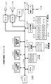
図1は、この第1の実施の形態の記録再生装置であるICレコーダを説明するためのブロック図である。図1に示すように、この実施の形態のICレコーダは、CPU(Central Processing Unit)101、プログラムや各種のデータが記憶されているROM(Read Only Memory)102、主に作業領域として用いられるRAM(Random Access Memory)103がCPUバス104を通じて接続されて、マイクロコンピュータの構成とされた制御部100を備えている。なお、RAM103は、後述もするように、圧縮データ領域103(1)と、PCM(Pulse Code Modulation)領域103(2)とが設けられている。
[First Embodiment]
[Overview of IC recorder configuration and operation]
FIG. 1 is a block diagram for explaining an IC recorder which is a recording / reproducing apparatus according to the first embodiment. As shown in FIG. 1, an IC recorder of this embodiment includes a CPU (Central Processing Unit) 101, a ROM (Read Only Memory) 102 storing programs and various data, and a RAM mainly used as a work area. A (Random Access Memory) 103 is connected via a
制御部100には、ファイル処理部110を通じてデータ記憶装置111が接続され、入力処理部120を通じてキー操作部121が接続されている。また、制御部100には、アナログ/デジタルコンバータ(以下、A/Dコンバータと略称する。)132を通じてマイクロホン131が接続され、デジタル/アナログコンバータ(以下、D/Aコンバータと略称する。)134を通じてスピーカ133が接続されている。また、制御部100には、LCD(Liquid Crystal Display)135が接続されている。なお、この実施の形態において、LCD135は、LCDコントローラの機能をも備えたものである。
A
さらに、制御部100には、データ圧縮処理部141、データ伸張処理部142、音声特徴解析部143、通信インターフェース(以下、通信I/Fと略称する。)144が接続されている。図1において、2重線で示したデータ圧縮処理部141、データ伸張処理部142、音声特徴解析部143は、制御部100のCPU101で実行されるソフトウェア(プログラム)によっても、その機能を実現することができるものである。
Further, a data
また、この実施の形態において、通信インターフェース144は、例えば、USB(Universal Serial Bus)やIEEE(Institute of Electrical and Electronics Engineers)1394などのデジタルインターフェースであり、接続端子145に接続されるパーソナルコンピュータ、デジタルカメラなどの種々の電子機器との間でデータの送受を行うことができるものである。
In this embodiment, the
この第1の実施の形態のICレコーダは、キー操作部121のRECキー(録音キー)211が押下操作されると、CPU101が各部を制御して録音処理を行う。この場合、マイクロホン131で集音され、A/Dコンバータ132でデジタル変換されると共に、データ圧縮処理部141の機能によりデータ圧縮された音声信号が、ファイル変換部110を通じてデータ記憶装置111の所定の記憶領域に記録される。
In the IC recorder of the first embodiment, when the REC key (recording key) 211 of the key operation unit 121 is pressed, the
この第1の実施の形態のデータ記憶装置111は、フラッシュメモリ、あるいは、フラッシュメモリを用いたメモリカードであり、後述もするように、データベース領域111(1)と音声ファイル111(2)が設けられたものである。
The
録音処理時において、この第1の実施の形態のICレコーダは、音声特徴解析部143の機能により、集音して録音(記録)する音声信号について、所定の処理単位毎に特徴解析を行い、特徴が変化したことを検出した場合に、その特徴が変化した時点にマーク(目印)を付すようにしている。そして、このマークを利用して、録音した音声信号から目的とする音声信号部分の検索を迅速に行うことができるようにしている。
During the recording process, the IC recorder according to the first embodiment performs a feature analysis for each predetermined processing unit on the sound signal to be collected and recorded (recorded) by the function of the sound
図2は、集音して録音する音声信号の変化点にマークを付すようにする処理の概要を説明するための図である。この第1の実施の形態のICレコーダにおいては、上述もしたように、マイクロホン131により集音された音声信号について、所定の処理単位毎に特徴解析を行う。
FIG. 2 is a diagram for explaining the outline of the process for marking a change point of an audio signal to be collected and recorded. In the IC recorder according to the first embodiment, as described above, the feature analysis is performed for each predetermined processing unit on the sound signal collected by the
そして、直前の特徴解析結果と比較することによって、無音部分や雑音部分から話音声部分に変化した変化点、あるいは、話音声部分であっても、話者が変化した変化点を検出し、当該音声信号上の変化点の位置(時間)を特定する。そして、その特定した位置を変化点情報(マーク情報)としてデータ記憶装置111に記憶しておくようにする。このように、音声信号上の変化点の位置を示す変化点情報を保持することが、集音して録音する音声信号に対してマークを付すことになる。
Then, by comparing with the previous feature analysis result, the change point changed from the silent part or the noise part to the spoken voice part, or the change point where the speaker changed even in the spoken voice part, The position (time) of the change point on the audio signal is specified. Then, the specified position is stored in the
具体的には、図2に示すように、会議の様子を録音するようにした場合、録音開始から10秒後に、Aさんが発言を始めたとする。この場合、Aさんの発言の開始前は、無音、あるいは、ざわめきや椅子を引く音、テーブルに何かがあたる音など、明瞭な話音声とは異なるいわゆる雑音などの無意味な音声が集音されおり、Aさんが発言を始め、その話音声が集音されることにより、集音した音声信号の特徴解析結果は、Aさんが発言を始める前とは明らかに異なることになる。 Specifically, as shown in FIG. 2, when recording the state of the conference, it is assumed that Mr. A starts speaking 10 seconds after the start of recording. In this case, before Mr. A's speech starts, silent or non-sensed sounds such as noise that is different from clear speech, such as a noise or a noise that pulls a chair, or a sound that hits a table are collected. Therefore, when Mr. A starts speaking and the speech is collected, the characteristic analysis result of the collected voice signal is clearly different from that before Mr. A starts speaking.
この集音して録音する音声信号の変化点を音声特徴解析部143において検出し、その変化点の音声信号上の位置を特定(取得)して、この特定した変化点情報(音声信号上の特定した位置情報)を図2におけるマークMK1としてデータ記憶装置111に記憶保持する。なお、図2においては、録音開始からの経過時間を変化点情報として記憶保持するようにしている場合の例を示している。
The voice
そして、Aさんの発言が終了した後、少し間をおいて、Bさんが発言を始めたとする。このBさんの発言開始の直前も、無音あるいは雑音である。この場合にも、Bさんが発言を始め、その話音声が集音されることにより、集音した音声信号の特徴解析結果は、Bさんが発言を始める前とは明らかに異なることになり、図2において、マークMK2が示すように、Bさんの発言の開始部分にマークを付すように、変化点情報(マークMK2)をデータ記憶装置111に記憶保持する。
Then, suppose that Mr. B started speaking after a while after Mr. A's speech ended. Immediately before Mr. B starts speaking, it is silent or noisy. Also in this case, when Mr. B starts speaking and the speech is collected, the characteristic analysis result of the collected voice signal is clearly different from that before Mr. B started speaking. In FIG. 2, as indicated by the mark MK2, the change point information (mark MK2) is stored and held in the
さらに、Bさんの発言の途中でCさんが割って入ったような場合も発生する。この場合には、Bさんの話し声と、Cさんの話し声とでは、異なっているために、集音した音声信号の解析結果も異なることになり、図2において、マークMK3が示すように、Cさんの発言の開始部分にマークを付すように、変化点情報(マークMK3)をデータ記憶装置111に記憶保持する。
Furthermore, a case may occur where Mr. C breaks in the middle of Mr. B's statement. In this case, since the voice of Mr. B is different from the voice of Mr. C, the analysis result of the collected voice signal is also different. As shown by mark MK3 in FIG. The change point information (mark MK3) is stored and held in the
このように、この実施の形態のICレコーダは、録音処理時において、集音した音声信号の特徴解析を行い、特徴が変化した音声信号上の位置を記憶保持することによって、音声信号の特徴が変化した時点にマークを付すようにすることができるようにしたものである。 As described above, the IC recorder according to this embodiment performs the feature analysis of the collected sound signal during the recording process, and stores and holds the position on the sound signal in which the feature has been changed. The mark can be attached at the time of change.
なお、図2において、マークMK1、MK2、MK3において、その他という欄が示すように、例えば、発言部分を音声認識してテキストデータに変換することにより、そのテキストデータを関連付けて記憶保持するようにしたり、その他の関連情報を一緒に記憶保持させるようにしたりすることもできるようにしている。 In FIG. 2, as indicated by the column “other” in the marks MK1, MK2, and MK3, for example, by recognizing a speech portion and converting it into text data, the text data is associated and stored. Or other related information can be stored and held together.
そして、この第1の実施の形態のICレコーダは、キー操作部121のPLAYキー(再生キー)212が押下操作されると、CPU101が各部を制御して再生処理を行う。すなわち、データ圧縮されてデータ記憶装置111の所定の記憶領域に記憶されている録音された音声信号(デジタル音声信号)がファイル処理部110を通じて読み出され、これがデータ伸張処理部142の機能により伸張処理されて、データ圧縮前の元のデジタル音声信号に復元される。この復元されたデジタル音声信号が、D/Aコンバータ134においてアナログ音声信号に変換され、これがスピーカ133に供給されて録音されて再生するようにされた音声信号に応じた音声が放音される。
In the IC recorder according to the first embodiment, when the PLAY key (reproduction key) 212 of the key operation unit 121 is pressed, the
この再生処理時に、この第1のICレコーダにおいては、キー操作部121のNEXTキー(次のマークへの位置付けを指示するキー)214やPREVキー(前のマークへの位置付けを指示するキー)215が操作された場合に、これに応じて、再生位置をすばやくマークが付与された位置に位置付けて、そこから再生を行うことができるようにしている。 At the time of this reproduction processing, in the first IC recorder, the NEXT key (key for instructing positioning to the next mark) 214 and the PREV key (key for instructing positioning to the previous mark) 215 of the key operation unit 121. In response to this, the playback position is quickly positioned at the position where the mark is given, and playback can be performed from there.
図3は、録音した音声信号の再生時に行われるマークが示す音声信号上の位置への位置付け動作を説明するための図であり、操作に応じて変化するLCD135の表示情報の変化を示す図である。図3に示すように、PLAYキー211が押下操作されると、上述もしたように、CPU101は各部を制御し、指示された録音音声信号の先頭から再生を開始する。
FIG. 3 is a diagram for explaining the positioning operation to the position on the audio signal indicated by the mark performed at the time of reproduction of the recorded audio signal, and is a diagram showing the change in the display information of the
そして、Aさんの発言部分においては、図2を用いて説明したように、録音処理時に付された(記憶保持された)マークMK1に基づいて、図3Aに示すように、Aさんの発言の開始時刻が表示されると共に、これが録音開始から最初に付したマークであることを示すSEQ−No.1という表示がされる。 In the remark part of Mr. A, as described with reference to FIG. 2, based on the mark MK1 (stored and held) at the time of the recording process, as shown in FIG. A start time is displayed, and SEQ-No. Indicating that this is the first mark added from the start of recording. 1 is displayed.
再生が続行され、Bさんの発言部分の再生が開始されると、図3Bに示すように、Bさんの発言の開始時刻が表示されると共に、これが録音開始から2番目に付したマークであることを示すSEQ−No.2という表示がされる。この後、PREVキー215が押下操作されると、CPU101は、図3Cに示すように、開始時刻が先頭から10秒後(0分10秒後)のマークMK1が示すAさんの発言の開始部分に再生位置を位置付け、そこから再生を再開する。
When playback is continued and playback of Mr. B's speech portion is started, the start time of Mr. B's speech is displayed as shown in FIG. 3B, and this is the second mark from the start of recording. SEQ-No. 2 is displayed. Thereafter, when the
この後、NEXTキーが押下操作されると、CPU101は、図3Dに示すように、開始時刻が先頭から1分25秒後のマークMK2が示すBさんの発言の開始部分に再生位置を位置付け、そこから再生を再開する。さらに、NEXTキーが押下操作されると、CPU101は、図3Eに示すように、開始時刻が先頭から2分30秒後のマークMK3が示すCさんの発言の開始部分に再生位置を位置付け、そこから再生を再開する。
Thereafter, when the NEXT key is pressed, as shown in FIG. 3D, the
このように、この実施の形態のICレコーダは、録音処理時において、集音した音声信号の特徴解析を自動的に行い、特徴の変化点にマークを付するようにすると共に、再生処理時においては、NEXTキー214、PREVキー215を操作することによって、付したマークが示す録音された音声信号上の位置に再生位置をすばやく位置付けて、そこから再生を行うようにすることができるものである。
As described above, the IC recorder of this embodiment automatically analyzes the characteristics of the collected audio signal during the recording process, and marks the change points of the characteristics, and at the time of the reproduction process. By operating the
これによって、ユーザは、すばやく目的とする話者(発言者)の発言部分に再生位置を位置付けて、録音した音声信号を再生して聴取することができるので、目的とする発言部分の議事録を迅速に作成することができる。 As a result, the user can quickly position the playback position on the speech portion of the target speaker (speaker) and play and listen to the recorded audio signal, so that the minutes of the target speech portion can be recorded. Can be created quickly.
なお、ここでは、説明を簡単にするため、変化点情報として、録音開始時点からの時刻情報を用いるようにしたが、これに限るものではなく、録音された音声信号のデータ記憶装置111の記録媒体上のアドレスを変化点情報として用いることもできる。
Here, for the sake of simplicity, the time information from the recording start time is used as the change point information. However, the present invention is not limited to this, and recording of the recorded audio signal in the
[ICレコーダの動作の詳細について]
次に、図4、図5のフローチャートを参照しながら、この第1の実施の形態のICレコーダにおける録音処理と再生処理とについて、詳細に説明する。
[Details of IC recorder operation]
Next, the recording process and the reproduction process in the IC recorder of the first embodiment will be described in detail with reference to the flowcharts of FIGS.
[録音処理について]
まず、録音処理について説明する。図4は、この第1の実施の形態のICレコーダにおいて行われる録音処理を説明するためのフローチャートである。図4に示す処理は、CPU101が各部を制御することにより行われる処理である。
[Recording process]
First, the recording process will be described. FIG. 4 is a flowchart for explaining a recording process performed in the IC recorder according to the first embodiment. The process illustrated in FIG. 4 is a process performed by the
この第1の実施の形態のICレコーダは、電源が投入された状態にあり、動作していないときには、ユーザからの操作入力待ちとなる(ステップS101)。ユーザが操作部121にある操作キーを押下すると、入力処理部120がそれを検知し、CPU101に通知するので、CPU101は、受け付けた操作入力は、RECキー211の押下操作か否かを判断する(ステップS102)。
When the IC recorder according to the first embodiment is in a state where the power is turned on and is not operating, it waits for an operation input from the user (step S101). When the user presses an operation key on the operation unit 121, the
ステップS102の判断処理において、受け付けた操作入力は、RECキー211の押下操作ではないと判断したときには、CPU101はユーザにより操作されたキーに応じた処理、例えば、PLAYキー212に応じた再生処理、NEXTキー124に応じた次のマークへの位置付け処理、PREVキー215に応じた1つ前のマークへの位置付け処理などを行うことになる(ステップS103)。もちろん、早送り処理や早戻し処理などを行うこともできるようにされている。
If it is determined in step S102 that the received operation input is not a pressing operation of the
ステップS102の判断処理において、RECキーが押下されたと判断した場合には、CPU101は、ファイル処理部110にファイル記録処理を行うように指示を出し、これに応じて、ファイル処理部110は、データ記録装置111に音声ファイル111(2)を作成する(ステップS104)。
If it is determined in step S102 that the REC key has been pressed, the
そして、CPU101は、キー操作部121のSTOPキー(停止キー)213が押下操作されたか否かを判断する(ステップS105)。ステップS105の判断処理において、STOPキー213が操作されたと判断したときには、後述もするように、所定の終了処理を行って(ステップS114)、この図4に示す処理を終了する。
Then, the
ステップS105の判断処理において、STOPキー213は操作されていないと判断したときには、CPU101は、A/Dコンバータ132にマイクロホン131を通じて入力されるアナログ音声信号をデジタル音声信号に変換することを指示し、集音音声のデジタル変換を行うようにする(ステップS106)。
If it is determined in step S105 that the
これにより、A/Dコンバータ132は、マイクロホン131を通じて入力されるアナログ音声信号を一定周期ごと(所定の処理単位ごと)に変換したデジタル音声信号を、RAM103のPCMデータ領域103(2)に書き込み、書き込んだことをCPU101に通知する(ステップS107)。
As a result, the A /
これを受けて、CPU101は、データ圧縮処理部141に対し、RAM104のPCMデータ領域103(2)に格納したデジタル音声信号(PCMデータ)をデータ圧縮するように指示する(ステップS108)。これに応じて、データ圧縮処理部141は、RAM103のPCMデータ領域103(2)のデジタル音声信号を圧縮処理し、圧縮したデジタル音声信号をRAM103の圧縮データ領域103(1)に書き込む(ステップS109)。
In response to this, the
そして、CPU101は、ファイル処理部110に対して、RAM103の圧縮データ領域103(1)の圧縮されたデジタル音声信号をデータ記憶装置111に作成した音声ファイル111(2)に書き込むことを指示し、これにより、ファイル処理部110により、RAM103の圧縮データ領域の圧縮されたデジタル音声信号が、データ記憶装置111の音声ファイル111(2)に書き込まれる(ステップS110)。
Then, the
ファイル処理部110は、圧縮されたデジタル音声信号の音声ファイル111(2)への書き込みを終了すると、これをCPU101に通知するので、CPU101は、音声特徴解析部143に対して、RAM103のPCMデータ領域103(2)に先に記録されたデジタル音声信号の特徴解析を指示し、音声特徴解析部143によって、RAM103のPCMデータ領域103(2)のデジタル音声信号の特徴を抽出する(ステップS111)。
When the
なお、音声特徴解析部143において行われるデジタル音声信号の特徴解析(特徴抽出)処理は、声紋分析、話速分析、間の取り方の分析、音声の強弱の分析などの種々の方法を用いることが可能である。ここでは説明を簡単にするため、この第1の実施の形態のICレコーダの音声特徴解析部143は、声紋分析を行うことにより、解析対象のデジタル音声信号の特徴を抽出するものとして説明する。
The feature analysis (feature extraction) processing of the digital voice signal performed in the voice
そして、音声特徴解析部143は、今回抽出した音声の特徴(声紋データ)と、過去に抽出した音声の声紋データとを比較し、入力された音声信号から抽出した特徴が、これまでの音声の特徴から変化したか否かを判断し、その判断結果をCPU101に対して通知するので、これに基づき、CPU101は、集音音声の特徴が変化したか否かを判断する(ステップS112)。
Then, the voice
ステップS112の判断処理において、変化がなかったと判断したときには、CPU101は、ステップS105からの処理を繰り返し、次の周期(次の処理単位)の音声信号についても、上述したステップS105からステップS112までの処理を行うようにする。
When it is determined in step S112 that there is no change, the
ステップS112の判断処理において、変化があったと判断したときには、CPU101は、「話者が切り替わった」と判断し、ファイル処理部110に対して、処理対象の音声信号上の音声の特徴の変化点にマークを付することを指示する(ステップS113)。これにより、ファイル処理部110は、データ記録装置111上のデータベース領域111(1)に当該音声ファイル111(2)に関する情報として、音声の特徴に変化のあった場所を示す情報として、当該音声ファイル111(2)の先頭からの時刻情報、あるいは、記録位置に対応するアドレス情報を書き込む。この場合、音声ファイルと音声の特徴に変化のあった場所を示す情報とは対応付けられて記憶される。
When it is determined in step S112 that there has been a change, the
このステップS113の処理の後、CPU101は、ステップS105からの処理を繰り返し、次の周期(次の処理単位)の音声信号についても、上述したステップS105からステップS112までの処理を行うようにする。
After the process of step S113, the
そして、ステップS105の判断処理において、ユーザがSTOPキー213を押下操作したと判断したときには、CPU101は、ファイル処理部110に対してデータ記憶装置111の音声ファイル111(2)へのデータの書き込みの停止を、データ圧縮処理部141に対して圧縮処理の停止を、A/Dコンバータ132に対してデジタル信号への変換の停止を指示する等の所定の終了処理を行って(ステップS114)、この図4に示す処理を終了する。
When it is determined in the determination process in step S105 that the user has pressed the
なお、音声特徴解析部143において行われる音声の特徴が変化したか否かの判断は、過去に抽出した音声の特徴データ(声紋データ)を保持しておき、これと新たに抽出した特徴データ(声紋データ)とを比較することにより行う。この場合、直前の1つの特徴データだけと比較するだけでよいのであれば、過去の特徴データは、常に直前の1つだけを保持しておけばよい。しかし、精度を向上させるため、過去の2つ以上の特徴データと比較し、2つ以上の違いが生じた場合に特徴が変化したと判断するようにする場合には、2つ以上の過去の特徴データを保持しておく必要がある。
Note that the voice
このように、この第1の実施の形態のICレコーダは、集音して録音する音声信号の特徴解析を行い、その集音音声信号の特徴の変化点を検出して、その変化点に相当する集音音声信号上の位置にマークを付すようにすることができるものである。 As described above, the IC recorder according to the first embodiment performs feature analysis of a sound signal to be collected and recorded, detects a change point of the feature of the collected sound signal, and corresponds to the change point. The mark can be attached to the position on the collected sound signal.
[再生処理について]
次に、再生処理について説明する。図5は、この第1の実施の形態のICレコーダにおいて行われる再生処理を説明するためのフローチャートである。図5に示す処理は、CPU101が各部を制御することにより行われる処理である。
[About playback processing]
Next, the reproduction process will be described. FIG. 5 is a flowchart for explaining the reproduction process performed in the IC recorder according to the first embodiment. The processing illustrated in FIG. 5 is processing performed by the
この第1の実施の形態のICレコーダの再生処理においては、図4を用いて説明したように、録音処理時に付される集音音声(集音して録音する音声)の特徴の変化点に付されたマークを利用して、録音された音声信号から迅速に目的とする音声信号部分を検出することができるようにしている。 In the playback process of the IC recorder of the first embodiment, as described with reference to FIG. 4, the characteristic change point of the collected voice (sound collected and recorded) added during the recording process is used. By using the attached mark, a target audio signal portion can be quickly detected from the recorded audio signal.
この第1の実施の形態のICレコーダは、電源が投入された状態にあり、動作していないときには、ユーザからの操作入力待ちとなる(ステップS201)。ユーザが操作部121にある操作キーを押下すると、入力処理部120がそれを検知し、CPU101に通知するので、CPU101は、受け付けた操作入力は、PLAYキー212の押下操作か否かを判断する(ステップS202)。
The IC recorder according to the first embodiment is in a state where power is turned on, and when not operating, the IC recorder waits for an operation input from the user (step S201). When the user presses an operation key on the operation unit 121, the
ステップS202の判断処理において、受け付けた操作入力は、PLAYキー212の押下操作ではないと判断したときには、CPU101はユーザにより操作されたキーに応じた処理、例えば、RECキー212に応じた録音処理、NEXTキー124に応じた次のマークへの位置付け処理、PREVキー215に応じた1つ前のマークへの位置付け処理などを行うことになる(ステップS203)。もちろん、早送り処理や早戻し処理などを行うこともできるようにされている。
If it is determined in step S202 that the received operation input is not a pressing operation of the
ステップS202の判断処理において、受け付けた操作入力は、PLAYキーの押下操作であると判断したときには、CPU101は、ファイル処理部110にデータ記録装置111上の音声ファイル111(2)の読み出しを指示する(ステップS204)。そして、CPU101は、キー操作部121のSTOPキー(停止キー)213が押下操作されたか否かを判断する(ステップS205)。
In the determination process of step S202, when it is determined that the received operation input is a PLAY key pressing operation, the
ステップS205の判断処理において、STOPキー213が操作されたと判断したときには、後述もするように、所定の終了処理を行って(ステップS219)、この図5に示す処理を終了することになる。
If it is determined in step S205 that the
ステップS205の判断処理において、STOPキー213が操作されていないと判断したときには、CPU101はファイル処理部110を制御し、データ記憶装置111の音声ファイル111(2)に記憶されている圧縮されたデジタル音声信号をシステムで規定された所定の処理単位の量だけ読み出し、RAM103の圧縮データ領域103(1)に書き込むようにする(ステップS206)。
If it is determined in step S205 that the
書き込みが終了すると、これがCPU101に通知されるので、CPU101は、データ伸張処理部142に対して、RAM103の圧縮データ領域103(1)の圧縮されたデジタル音声信号の伸長処理を行うことを指示し、データ伸張処理部142によって圧縮されたデジタル音声信号の伸張処理を行って、RAM103のPCMデータ領域103(2)に書きこむようにする(ステップS207)。
When the writing is completed, the
書き込みが終了すると、これがCPU101に通知されるので、CPU101は、D/Aコンバータ134に対し、RAM103のPCMデータ領域103(2)に格納されたデジタル音声信号(伸張されたデジタル音声信号)をアナログ音声信号に変換し、スピーカ133に供給するように制御する。
When the writing is completed, this is notified to the
これにより、データ記憶装置111の音声ファイル111(2)に記憶保持されているデジタル音声信号に応じた音声が、スピーカ133から放音するようにされる。そして、D/Aコンバータ134は、D/A変換したアナログ音声信号を出力したことをCPU101に通知してくるので、CPU101は、キー操作部121の操作キーが操作されたか否かを判断する(ステップS209)。
As a result, sound corresponding to the digital sound signal stored and held in the sound file 111 (2) of the
ステップS209の判断処理において、操作キーは操作されていないと判断したときには、ステップS205からの処理を繰り返し、データ記憶装置111の音声ファイル111(2)のデジタル音声信号の再生を続行する。
If it is determined in step S209 that the operation key has not been operated, the processing from step S205 is repeated, and the reproduction of the digital audio signal of the audio file 111 (2) in the
ステップS209の判断処理において、操作キーが操作されたと判断したときには、CPU101は、操作されたキーは、PREVキー215か否かを判断する(ステップS210)。ステップS210の判断処理において、PREVキー215が操作されたと判断したときには、CPU101は、ファイル処理部110に対して音声ファイル111(2)からのデジタル音声信号の読み出しの停止を指示し、データ伸張処理部142に対して伸長処理の停止を指示し、D/Aコンバータ134に対してアナログ信号への変換の停止を指示する(ステップS211)。
When determining in step S209 that the operation key is operated, the
次に、CPU101は、ファイル処理部110にデータ記憶装置111のデータベース領域111(1)から現在再生している位置の直前のマークの情報(変化点情報)を読み出すよう指示し、その読み出されたマークの情報によって指示される音声信号上の位置に再生位置を位置付け、そこから再生を開始するようにし(ステップS212)、図3を用いて説明したように、位置付けに用いたマークの情報に応じた再生位置情報を表示して(ステップS213)、ステップS205からの処理を繰り返す。
Next, the
ステップS210の判断処理において、操作されたキーは、PREVキー215ではないと判断されたときには、CPU101は、操作されたキーは、NEXTキー214か否かを判断する(ステップS214)。ステップS214の判断処理において、NEXTキー214が操作されたと判断したときには、CPU101は、ファイル処理部110を制御し、音声ファイル111(2)からのデジタル音声信号の読み出しの停止を、データ伸張処理部142に伸長処理の停止を、D/Aコンバータ134にアナログ信号への変換の停止を、それぞれ指示する(ステップS215)。
When it is determined in step S210 that the operated key is not the
次に、CPU101は、ファイル処理部110にデータ記憶装置111のデータベース領域111(1)から現在再生している位置の直後のマークの情報(変化点情報)を読み出すよう指示し、その読み出されたマークの情報によって指示される音声信号上の位置に再生位置を位置付け、そこから再生を開始するようにし(ステップS216)、図3を用いて説明したように、位置付けに用いたマークの情報に応じた再生位置情報を表示して(ステップS217)、ステップS205からの処理を繰り返す。
Next, the
ステップS214の判断処理において、操作されたキーは、NEXTキー214ではないと判断されたときには、CPU101は、操作されたキーに応じた処理、例えば、早送り、早戻しなどの操作されたキーに応じた処理を行って、ステップS205からの処理を繰り返す。
When it is determined in step S214 that the operated key is not the
このように、録音時にICレコーダが音声の特徴に変化があったことを話者の切り替わりと判断し,その位置にマークを自動的につけることで,ユーザは再生時にPREVキー215、NEXTキー214を押下操作して簡単に各発言の先頭位置を呼び出すことが可能になり、議事録作成時において、ある発言を繰り返し再生させたいときや、重要な発言を見つけ出す際の手間が大幅に削減できる。すなわち、録音された音声信号中から、目的とする音声信号部分を迅速に検索することができる。
As described above, when the IC recorder determines that the voice characteristics have changed during recording, it is determined that the speaker is switched, and a mark is automatically added at that position, so that the user can use the
しかも、集音音声の特徴の変化点は自動検出され、その変化点へのマークの付与も自動的に行われるので、変化点へのマークの付与に関し、ユーザの手を煩わせることは一切ない。 In addition, the change point of the characteristics of the collected sound is automatically detected, and the mark is automatically assigned to the change point, so that the user's hand is not troubled about the mark assignment to the change point. .
[第1の実施の形態の変形例]
ところで、会議の様子を録音し、この録音に基づいて議事録を作成する場合、誰がどこで発言をしたかを、録音音声を再生することなく知ることができればより便利である。そこで、この変形例のICレコーダは、会議への出席者の音声の特徴解析結果である声紋データを、各出席者を識別するためのシンボルと対応付けて記憶させておくことによって、話者を特定できるマークを付すようにしたものである。
[Modification of the first embodiment]
By the way, when recording the state of a meeting and creating a minutes based on this recording, it is more convenient if it is possible to know who has spoken and where without replaying the recorded sound. In view of this, the IC recorder of this modification example stores voiceprint data, which is a voice characteristic analysis result of attendees attending a conference, in association with symbols for identifying each attendee, thereby allowing a speaker to be stored. A mark that can be identified is attached.
この変形例のICレコーダは、図1に示した第1の実施の形態のICレコーダと同様に構成されるものである。しかし、この変形例のICレコーダの例えば外部記憶装置の111やRAM103の記憶領域には、会議の出席者についての音声特徴データベースを形成するようにしたものである。なお、以下の説明においては、音声特徴データベースは、外部記憶装置111に形成するものとして説明する。
The IC recorder of this modification is configured similarly to the IC recorder of the first embodiment shown in FIG. However, an audio feature database for the attendees of the conference is formed in the storage area of, for example, the
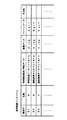
図6は、この変形例のICレコーダの外部記憶装置111の記憶領域に形成される音声データベースの一例を説明するための図である。図6に示すように、この例の音声データベースは、会議の出席者を識別するための識別子(例えば、登録順に応じたシーケンスナンバなど)と、会議の出席者の名前、会議の出席者の音声の特徴解析結果である声紋データ、会議の出席者の顔写真などの画像データ、会議の出席者のそれぞれに割り当てられたアイコンデータ、その他、テキストデータなどからなるものである。
FIG. 6 is a diagram for explaining an example of a voice database formed in the storage area of the
声紋データ、画像データ、アイコンデータ、その他のデータのそれぞれは、ファイルの形式で外部記憶装置111に記憶されており、それが会議の各出席者の識別子をキー情報(対応付け情報)として記憶保持されている。なお、特徴解析結果である声紋データは、会議に先だって、会議の出席者の音声を集音し、特徴解析を行うことにより予め得るようにしたものである。
Each of the voiceprint data, image data, icon data, and other data is stored in the
すなわち、この例のICレコーダは、音声データベース作成モードを有するものである。そして、音声データベース作成モードが選択された場合には、会議の出席者の音声を集音し、この集音音声の特徴解析を音声特徴解析部143で行って声紋データを得て、この声紋データをシーケンスナンバなどの識別子と対応付けて、外部記憶装置111の記憶領域に記憶することができるものである。
That is, the IC recorder of this example has a voice database creation mode. When the voice database creation mode is selected, the voices of the attendees of the conference are collected, and the voice analysis is performed by the voice
識別子と声紋データ以外の情報である、名前、画像データ、アイコンデータなどの情報は、接続端子145に接続される例えばパーソナルコンピュータなどを通じて、この例のICレコーダに供給され、図6に示したように、対応する識別子、声紋データと関連付けられて記憶保持するようにされる。もちろん、名前などは、ICレコーダのキー操作部121に設けられている操作キーを操作して入力することも可能である。また、画像データは、接続端子145に接続されるデジタルカメラから取り込むことも可能である。
Information other than the identifier and voiceprint data, such as name, image data, and icon data, is supplied to the IC recorder of this example through, for example, a personal computer connected to the
そして、この例のICレコーダもまた、図1、図2および図4を用いて説明したように、集音音声の特徴解析を行って、声紋データの変化点を検出し、その変化点に対応する音声信号上の位置にマークを自動的に付与していくのであるが、変化点を検出した場合に、最新の集音音声の声紋データと、音声データベースの声紋データとのマッチングを行い、声紋データが一致した会議の出席者の識別子を付与するマークに含めるようにしている。 As described with reference to FIGS. 1, 2, and 4, the IC recorder of this example also performs a feature analysis of the collected voice, detects a change point of voiceprint data, and responds to the change point. When a change point is detected, the voiceprint data of the latest collected voice is matched with the voiceprint data of the voice database when a change point is detected. It is included in the mark that gives the identifier of the meeting attendee whose data matches.
図7は、この変形例のICレコーダにおいて行われる集音して録音する音声信号にマークを付す処理の概要を説明するための図である。基本的にマークを付す処理は、図2を用いて説明した場合と同様に行なわれる。しかし、マークには、話者の識別子が付加される。 FIG. 7 is a diagram for explaining the outline of the process of adding marks to the audio signal to be collected and recorded in the IC recorder of this modification. The process of adding marks is basically performed in the same manner as described with reference to FIG. However, the speaker identifier is added to the mark.
図7に示すように、会議の様子を録音するようにした場合、録音開始から10秒後に、Aさんが発言を始めたとする。この場合、Aさんの発言の開始前は、無音、あるいは、ざわめきや椅子を引く音、テーブルに何かがあたる音など、明瞭な話音声とは異なるいわゆる雑音などの無意味な音声が集音されているので、集音した音声信号の特徴解析結果は、Aさんが発言を始める前とは明らかに異なることになる。この変化点の音声信号上の位置を特定(取得)して、この特定した変化点情報を図7におけるマークMK1として記憶保持する。 As shown in FIG. 7, when recording the state of the meeting, it is assumed that Mr. A starts speaking after 10 seconds from the start of recording. In this case, before Mr. A's speech begins, silent or nonsense speech such as noise that is different from clear speech is collected, such as a noise or a noise of pulling a chair, or a sound hitting a table. Therefore, the characteristic analysis result of the collected audio signal is clearly different from that before Mr. A started speaking. The position of the change point on the audio signal is specified (acquired), and the specified change point information is stored and held as a mark MK1 in FIG.
この場合に、最新の声紋データと音声データベースの声紋データとのマッチングを行い、一致する声紋データに対応する話者(会議の出席者)の識別子をマークMK1に含めるようにする。なお、図7においても、録音開始からの経過時間を変化点情報として記憶保持している場合を示している。 In this case, the latest voiceprint data is matched with the voiceprint data of the voice database, and the identifier of the speaker (conference attendee) corresponding to the matched voiceprint data is included in the mark MK1. FIG. 7 also shows a case where the elapsed time from the start of recording is stored and held as change point information.
そして、Aさんの発言が終了した後、少し間をおいて、Bさんが発言を始めたとする。このBさんの発言の直前も、無音あるいは雑音であったとする。この場合にも、Bさんが発言を始め、それが集音されることにより、集音した音声信号の特徴解析結果は、Bさんが発言を始める前とは明らかに異なることになり、図7において、マークMK2が示すように、Bさんの発言の開始部分にマークを付すように、変化点情報(マークMK2)を記憶保持する。 Then, suppose that Mr. B started speaking after a while after Mr. A's speech ended. It is assumed that there was no sound or noise immediately before Mr. B's remark. Also in this case, when Mr. B starts speaking and is collected, the characteristic analysis result of the collected voice signal is clearly different from that before Mr. B starts speaking. As shown by the mark MK2, the change point information (mark MK2) is stored and held so as to mark the start part of Mr. B's speech.
この場合にも、最新の声紋データと音声データベースの声紋データとのマッチングを行い、一致する声紋データに対応する話者(会議の出席者)の識別子をマークMK2に含めるようにする。 Also in this case, matching is performed between the latest voiceprint data and the voiceprint data of the voice database, and the identifier of the speaker (conference attendee) corresponding to the matching voiceprint data is included in the mark MK2.
さらに、Bさんの発言の途中でCさんが割って入ったような場合も発生するが、この場合には、Bさんの話し声とCさんの話し声とでは異なっているために、集音した音声信号の解析結果も異なることになり、図7において、マークMK3が示すように、Cさんの発言の開始部分にマークを付すように、変化点情報(マークMK3)を記憶保持する。 Furthermore, there may be a case where Mr. C breaks in the middle of Mr. B's speech. In this case, the voice of the collected sound is different because Mr. B's voice is different from Mr. C's voice. The signal analysis results are also different. In FIG. 7, as indicated by the mark MK3, the change point information (mark MK3) is stored and held so that a mark is attached to the start portion of Mr. C's speech.
この場合にも、最新の声紋データと音声データベースの声紋データとのマッチングを行い、一致する声紋データに対応する話者(会議の出席者)の識別子をマークMK3に含めるようにする。 Also in this case, the latest voiceprint data is matched with the voiceprint data of the voice database, and the identifier of the speaker (conference attendee) corresponding to the matched voiceprint data is included in the mark MK3.
このようにすることによって、録音した音声信号のどの部分が誰の発言部分であるかを特定することができるようにされ、例えば、Aさんの発言部分だけを再生するようにしてAさんの発言の要旨をまとめるなどのことが簡単にできるようになる。 By doing so, it becomes possible to specify which part of the recorded audio signal is who's utterance. For example, only Mr. A's utterance is reproduced and Mr. A's utterance is reproduced. It becomes easy to summarize the summary of.
なお、この変形例の各マークのその他の情報は、例えば、集音音声の音声認識を行って、集音音声をテキストデータに変換し、このテキストデータをその他の情報としてファイル形式(テキストデータファイル)で記憶保持するようにしている。このテキストデータを用いることにより、議事録や発言の要約を迅速に作成することができるようにされる。 The other information of each mark of this modification is, for example, by performing voice recognition of the collected voice, converting the collected voice into text data, and using this text data as other information in a file format (text data file ) Is stored and retained. By using this text data, minutes and summaries of statements can be quickly created.
そして、この変形例のICレコーダにおいても、図1、図3、図5を用いて説明した場合と同様にして、録音音声の再生を行うことができるようにされる。そして、この変形例のICレコーダの場合には、録音音声における各発言者の発言部分の録音音声を再生することなく特定することができるようにされる。 Also in this modified example of the IC recorder, the recorded voice can be reproduced in the same manner as described with reference to FIGS. And in the case of the IC recorder of this modification, it is possible to specify without reproducing the recorded voice of the utterance part of each speaker in the recorded voice.
図8は、録音した音声信号の再生時に行われるマークへの位置付け動作を説明するための図であり、操作に応じて変化するLCD135の表示情報の変化を示す図である。図8に示すように、PLAYキー211が押下操作されると、上述もしたように、CPU101は各部を制御し、指示された録音音声信号の先頭から再生を開始するようにする。
FIG. 8 is a diagram for explaining an operation of positioning a mark performed when a recorded audio signal is reproduced, and is a diagram showing a change in display information on the
そして、Aさんの発言部分においては、図7を用いて説明したように、録音処理時に付された(記憶保持された)マークMK1に基づいて、図8Aに示すように、Aさんについての、発言の開始時刻D(1)、話者の画像データに応じた顔写真D(2)、話者の名前D(3)、発言の最初の部分のテキストデータD(4)が表示されると共に、再生中表示D(5)が表示される。 In Mr. A's remarks part, as described with reference to FIG. 7, based on the mark MK1 (stored and held) during the recording process, as shown in FIG. A speech start time D (1), a face photo D (2) corresponding to the speaker's image data, a speaker's name D (3), and text data D (4) of the first part of the speech are displayed. During playback, display D (5) is displayed.
そして、再生が続行され、Bさんの発言部分の再生が開始されると、録音時に付されたマークMK2に基づいて、図8Bに示すように、Bさんについての、発言の開始時刻D(1)、話者の画像データに応じた顔写真D(2)、話者の名前D(3)、発言の最初の部分のテキストデータD(4)が表示されると共に、再生中表示D(5)が表示される。 Then, when the reproduction is continued and the reproduction of Mr. B's speech part is started, the message start time D (1) for Mr. B is shown in FIG. 8B based on the mark MK2 attached at the time of recording. ), A face photograph D (2) corresponding to the image data of the speaker, a name D (3) of the speaker, and text data D (4) of the first part of the utterance, and a display D (5) during playback ) Is displayed.
この後、PREVキー215が押下操作されると、CPU101は、図8Cに示すように、開始時刻が先頭から10秒後(0分10秒後)のマークMK1が示すAさんの発言の開始部分に再生位置を位置付け、そこから再生を開始するようにする。この場合には、図8Aの場合と同様に、Aさんについての、発言の開始時刻D(1)、話者の画像データに応じた顔写真D(2)、話者の名前D(3)、発言の最初の部分のテキストデータD(4)が表示されると共に、再生中表示D(5)が表示される。
Thereafter, when the
この後、NEXTキーが押下操作されると、CPU101は、図8Dに示すように、開始時刻が先頭から1分25秒後のマークMK2が示すBさんの発言の開始部分に再生位置を位置付け、そこから再生を開始するようにする。この場合には、図8Bの場合と同様に、Bさんについての、発言の開始時刻D(1)、話者の画像データに応じた顔写真D(2)、話者の名前D(3)、発言の最初の部分のテキストデータD(4)が表示されると共に、再生中表示D(5)が表示される。
Thereafter, when the NEXT key is pressed, as shown in FIG. 8D, the
さらに、NEXTキーが押下操作されると、CPU101は、図8Eに示すように、開始時刻が先頭から2分30秒後のマークMK3が示すCさんの発言の開始部分に再生位置を位置付け、そこから再生を開始するようにする。この場合には、Cさんについての、発言の開始時刻D(1)、話者の画像データに応じた顔写真D(2)、話者の名前D(3)、発言の最初の部分のテキストデータD(4)が表示されると共に、再生中表示D(5)が表示される。
Further, when the NEXT key is pressed, the
なお、この変形例において、例えばAさんの発言部分を再生中にNEXTキーまたはPREVキーをすばやく2回押下すると、次にAさんの発言部分が出現する部分またはこれ以前にAさんの発言部分が出現した部分に再生位置を位置付け、そこから再生を開始するモードを付加してもよい。つまり、この操作を繰り返すことにより、Aさんの発言部分のみを辿って、あるいは遡って再生させることができる。もちろん、NEXTキーやPREVキーではなく、このモードを明示的に示す操作キーを設けてもよく、その場合には自動的に次々とAさんの発言部分が再生されるようにする。 In this modification, for example, when the NEXT key or PREV key is pressed twice quickly while Mr. A's speech part is being played back, the part where Mr. A's speech part appears next or before that, A mode may be added in which a playback position is positioned at an appearing portion and playback is started from there. In other words, by repeating this operation, only Mr. A's remark part can be traced or reproduced retroactively. Of course, instead of the NEXT key or PREV key, an operation key that explicitly indicates this mode may be provided. In this case, the remark portion of Mr. A is automatically reproduced one after another.
このように、この変形例のICレコーダは、録音処理時において、集音した音声信号の特徴解析を自動的に行い、特徴の変化点にマークを付与するようにすると共に、再生処理時においては、NEXTキー214、PREVキー215を操作することによって、付与されたマークが示す録音された音声信号上の位置に再生位置をすばやく位置付けて、そこから再生を行うようにすることができるものである。
As described above, the IC recorder of this modified example automatically performs the feature analysis of the collected audio signal at the time of the recording process, adds a mark to the change point of the feature, and at the time of the reproduction process. By operating the
しかも、録音された音声信号の変化点においては、誰の発言部分であるかを、話者の名前の表示や顔写真の表示により明確に示すことができるので、目的とする話者の発言部分を迅速に検索することができると共に、特定の話者の発言部分のみを再生するようにするなどのことが簡単にできる。もちろん、話者を特定するための情報として、各話者に固有のアイコンデータに応じたアイコンを表示するようにしてもよい。また、発言の最初の部分のテキストデータを表示することもできるので、目的とする発言部分か否かを判断する際に役立てることができる。 Moreover, at the change point of the recorded audio signal, it is possible to clearly indicate who is speaking by displaying the name of the speaker or displaying a face photo. Can be searched quickly, and only the utterance portion of a specific speaker can be reproduced. Of course, as information for specifying a speaker, an icon corresponding to icon data unique to each speaker may be displayed. In addition, since the text data of the first part of the utterance can be displayed, it can be used when determining whether or not the utterance part is the target.
そして、この変形例のICレコーダのユーザは、再生時の表示情報をも利用して、目的とする人の発言部分に再生位置を迅速に位置付けて、録音した音声信号を再生して聴取することができるので、目的とする発言部分の議事録を迅速に作成することができる。 Then, the user of the IC recorder of this modified example uses the display information at the time of reproduction to quickly position the reproduction position in the remarked part of the intended person and reproduce and listen to the recorded audio signal. Therefore, it is possible to quickly create the minutes of the target remark part.
換言すれば、録音後に録音音声信号をいちいち再生することなく、どこに誰の発言があるのかを視覚的に把握することができ、特定の話者の発言を簡単に探し出すことが可能になる。シンボルには文字列や記号の他に話者の顔写真など、より話者を特定し易くできるような情報が利用できるので、検索性が向上する。 In other words, without replaying the recorded audio signal after recording, it is possible to visually grasp who is speaking, and it is possible to easily find the speech of a specific speaker. As the symbols, in addition to character strings and symbols, information that makes it easier to specify the speaker, such as a photograph of the speaker's face, can be used, so searchability is improved.
また、音声の特徴が未登録の話者(登録済みであってもICレコーダが識別できなかった場合)の発言には未登録話者であることを意味するシンボルを対応付けておくことで、その部分を見つけ易くできる。この場合、議事録作成者は、未登録話者の発言部分を再生し、それが誰であるかを判断すればよい。 In addition, by associating a utterance of a speaker whose voice characteristics are unregistered (when the IC recorder cannot be identified even though it is registered) with a symbol indicating that the speaker is an unregistered speaker, You can easily find that part. In this case, the minutes maker may reproduce the utterance part of the unregistered speaker and determine who the person is.
未登録話者が誰であるかがわかったときには、それが登録済みの話者であったならば、その話者に対応付けられたシンボルをマークとして付け直せるようにすることもできる。また、未登録の話者であった場合は,話者の新規登録操作を行えるようにすることもできる。音声の特徴は録音音声から抽出し、対応付けるシンボルはICレコーダに予め登録済みの記号や文字列入力、ICレコーダにカメラ撮影機能があれば撮影した画像,または外部機器から取り込んだ画像データなどを用いる。 When it is known who the unregistered speaker is, if it is a registered speaker, a symbol associated with the speaker can be re-marked. If the speaker is unregistered, the speaker can be newly registered. The features of the sound are extracted from the recorded sound, and the symbol to be associated is input with a symbol or character string registered in advance in the IC recorder, a photographed image if the IC recorder has a camera photographing function, or image data captured from an external device. .
なお、この変形例のICレコーダの録音処理は、図4を用いて説明した録音処理と同様に行われるが、ステップS113の話者の切り替わりのマークMK1、MK2、MK3、…を付与する処理において、音声データベースの声紋データとのマッチングを行って、該当する話者の識別子が付加するようにされる。また、該当する声紋データが無かった場合には、該当なしを示すマークが付与されることになる。 The recording process of the IC recorder of this modification is performed in the same manner as the recording process described with reference to FIG. 4, but in the process of assigning speaker switching marks MK1, MK2, MK3,. Then, matching with the voice print data of the voice database is performed, and the identifier of the corresponding speaker is added. Further, when there is no corresponding voiceprint data, a mark indicating no corresponding is given.
また、この変形例のICレコーダの再生処理は、図5を用いて説明した再生処理と同様に行われるが、ステップS213、ステップS217の再生位置情報の表示処理において、話者の顔写真や氏名、発言内容のテキストデータなどが表示するようにされることになる。 Further, the reproduction process of the IC recorder of this modification is performed in the same manner as the reproduction process described with reference to FIG. 5, but in the reproduction position information display process in steps S213 and S217, the face photograph of the speaker and the name The text data of the content of the utterance will be displayed.
なお、この変形例のICレコーダの場合にも、変化点情報として、録音開始時点からの時刻を用いるようにしたが、これに限るものではなく、録音された音声信号のデータ記憶装置111の記録媒体上のアドレスを変化点情報として用いるようにしてもよい。
Also in the case of the IC recorder of this modification, the time from the recording start time is used as the change point information. However, the present invention is not limited to this, and recording of the recorded audio signal in the
[マーク付与処理の実行タイミングについて]
上述した第1の実施の形態のICレコーダ、第1の実施の形態の変形例のICレコーダにおいては、録音処理時に集音音声の変化点を検出し、その変化点に対応する音声信号上の位置にマークを付すようにしたが、これに限るものではない。録音処理終了後において、マークを付すようにすることができる。すなわち、再生処理時にマークを付すようにしたり、あるいは、マーク付与処理だけを行うようにしたりすることが可能である。
[Mark execution timing]
In the IC recorder according to the first embodiment and the IC recorder according to the modification of the first embodiment described above, a change point of the collected sound is detected during the recording process, and an audio signal corresponding to the change point is detected. Although the mark is attached to the position, it is not limited to this. A mark can be added after the recording process is completed. That is, it is possible to add a mark at the time of reproduction processing, or to perform only the mark addition processing.
図9は、録音処理終了後において、録音した音声信号の変化点にマークを付すようにする処理を説明するためのフローチャートである。すなわち、図9に示す処理は、再生処理時において録音音声の変化点にマークを付すようにする場合、あるいは、録音音声の変化点に対してマーク付与処理だけを独立に行う場合において行われるものである。この図9に示す処理もまた、ICレコーダのCPU101が各部を制御することにより行なわれる処理である。
FIG. 9 is a flowchart for explaining a process of marking a change point of a recorded audio signal after the recording process is completed. That is, the process shown in FIG. 9 is performed when a mark is added to the change point of the recorded sound at the time of the reproduction process, or when only the mark providing process is performed independently for the change point of the recorded sound. It is. The processing shown in FIG. 9 is also processing performed by the
まず、CPU101は、ファイル処理部104を制御して、データ記憶装置111の音声ファイルにデータ圧縮されて記憶されている録音音声信号を所定単位分づつ読み出し(ステップS301)、全ての録音音声信号の読み出しを終了しているか否かを判断する(ステップS302)。
First, the
ステップS302の判断処理において、全ての録音音声信号が読み出されていないと判断したときには、CPU101は、データ伸張処理部142を制御して、データ圧縮されている録音音声信号の伸張処理を行う(ステップS303)。この後、CPU101が、音声特徴解析部143を制御して、伸張した音声信号の特徴解析を行って、声紋データを得て、先に取得した声紋データと比較することによって、録音音声信号の特徴が変化したか否かを判断する(ステップS305)。
If it is determined in step S302 that all the recorded audio signals have not been read, the
ステップS305の判断処理において、録音音声信号の特徴は変化していないと判断したときには、ステップS301からの処理を繰り返すようにする。また、ステップS305の判断処理において、録音音声信号の特徴が変化したと判断したときには、CPU101は、「話者が切り替わった」と判断し、ファイル処理部110に音声の特徴に変化があった場所にマークを付加することを指示する(ステップS306)。
If it is determined in step S305 that the characteristics of the recorded audio signal have not changed, the processing from step S301 is repeated. If it is determined in the determination process in step S305 that the characteristics of the recorded voice signal have changed, the
これにより、ファイル処理部110は、データ記録装置111上のデータベース領域111(1)に当該音声ファイル111(2)に関する情報として、音声の特徴に変化のあった場所を示す情報として、ファイルの先頭からの時刻情報、あるいは、記録位置に対応するアドレス情報を書き込む。この場合、音声ファイルと音声の特徴に変化のあった場所を示す情報とは対応付けられて記憶される。
As a result, the
このステップS306の処理の後、CPU101は、ステップS301からの処理を繰り返し、次の周期(次の処理単位)の音声信号についても同様の処理を行う。そして、ステップS302の判断処理において、全ての録音音声信号について読み出しが終了していると判断したときには、所定の終了処理を行って(ステップS307)、この図9に示す処理を終了する。
After the processing in step S306, the
これにより、録音処理後において、再生処理時に録音音声の変化点を検出し、当該録音音声信号に対してマークを付与するようにしたり、あるいは、録音音声に対してマーク付与処理だけを独立に行うようにしたりすることができる。再生処理時において、マークの付与を行う場合には、図9に示したステップS303で伸張処理された音声信号をD/A変換し、D/A変換後のアナログ音声信号をスピーカ133に供給するようにすればよい。
As a result, after the recording process, the change point of the recorded voice is detected during the reproduction process, and a mark is given to the recorded voice signal, or only the mark giving process is independently performed on the recorded voice. And so on. When adding marks during reproduction processing, the audio signal expanded in
このように、録音後に録音音声信号の特徴の変化点に対してマークを付与するようにすることによって、録音時の処理の負荷と消費電力を軽減することが期待できる。また、ユーザがすべての録音において自動マーク付けを希望しない場合もある。録音時の自動マーク付け機能のオン/オフ設定ができるようにしてもよい。そして、ユーザがオフに設定したまま録音してしまった場合に、後でマーク付けが必要になった場合には、上述のようにして、録音処理後においても、録音音声信号に対してマーク付けができるので、非常に便利である。 As described above, it is expected that the processing load and power consumption during recording can be reduced by adding marks to the changing points of the characteristics of the recorded audio signal after recording. Also, the user may not want automatic markup for all recordings. It may be possible to turn on / off the automatic marking function during recording. If the user has recorded with the recording set to OFF, and marking is necessary later, the recorded audio signal is marked even after the recording process as described above. Is very convenient.
また、上述したように、録音された音声信号に対するマーク付けが可能であるので、録音機能を持たないが信号処理機能を備えた機器への適用が可能になる。例えば、パーソナルコンピュータのアプリケーションソフトに、この発明を適用することも可能である。すなわち、音声録音機器で録音された音声信号をパーソナルコンピュータに転送し、このパーソナルコンピュータ上で動作する上述の信号処理アプリケーションソフトにより、マーク付けをすることができる。 Further, as described above, since the recorded audio signal can be marked, it can be applied to a device that does not have a recording function but has a signal processing function. For example, the present invention can be applied to application software of a personal computer. That is, an audio signal recorded by an audio recording device can be transferred to a personal computer and marked by the above-described signal processing application software operating on the personal computer.
また、この発明を適用した機器で作成したデータを、ネットワークなどを介して共有することで、このデータから議事録を書き起こすことなく、このデータそのものを議事録として用いることも可能になる。 Further, by sharing data created by a device to which the present invention is applied via a network or the like, it is possible to use the data itself as a minutes without writing the minutes from the data.
したがって、この発明は、録音機器だけでなく、信号処理が可能な種々の電子機器に適用可能であり、既に録音済みの音声信号であっても、この発明を適応したで電子機器で処理することにより、同様の結果を得ることができる。すなわち、議事録の作成を効率的に行うことができるようにされる。 Therefore, the present invention can be applied not only to a recording device but also to various electronic devices capable of signal processing, and even an already recorded audio signal is processed by the electronic device by applying the present invention. Thus, the same result can be obtained. That is, the minutes can be created efficiently.
また、上述もしたように、図1を用いて説明した第1の実施の形態のICレコーダは、通信I/F144を備えており、パーソナルコンピュータなどの電子機器に接続可能である。そこで、上述した第1の実施の形態のICレコーダで録音されると共に、変化点にマークが付すようにされた音声信号(デジタル音声信号)をパーソナルコンピュータに転送するようにすれば、パーソナルコンピュータの大きな表示画面の表示装置を通じて、詳細情報をより多く表示し、目的とする発言者の発言部分を迅速に検索することができる。
As described above, the IC recorder according to the first embodiment described with reference to FIG. 1 includes the communication I /
図10、図11は、上述した第1の実施の形態のICレコーダからパーソナルコンピュータに転送された録音音声信号、付与された変化点情報(マーク情報)に基づいて、パーソナルコンピュータに接続された表示装置200の表示画面への変化点情報の表示例を説明するための図である。 10 and 11 show the display connected to the personal computer based on the recorded audio signal transferred from the IC recorder of the first embodiment described above to the personal computer and the given change point information (mark information). 6 is a diagram for explaining a display example of change point information on a display screen of the apparatus 200. FIG.
図10の場合には、録音音声信号に対応する時間帯表示201と、その時間帯表示201の該当位置に、マーク表示(変化点表示)MK1、MK2、MK3、MK4、…を表示するようにする。このようにすれば、複数の変化点の位置を一見して認識することができる。そして、例えばマウスなどのポインティングデバイスを用いて、目的とするマーク表示にカーソルを位置付けてクリックすることにより、その位置から録音音声の再生を行うようにすることなどができるようにされる。
In the case of FIG. 10, the
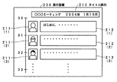
また、図11の場合には、図8に示した表示を、表示装置200の表示画眼に複数個いっぺんに表示するようにしたものであり、話者の顔写真211(1)、211(2)、211(3)、…や発言内容に応じたテキストデータ212(1)、212(2)、212(3)、…を表示して、目的とする話者の発言部分を迅速に検索するなどのことができるようにされる。また、パーソナルコンピュータの機能を用いて、タイトル表示210を行うようにすることもできる。 In the case of FIG. 11, a plurality of the displays shown in FIG. 8 are displayed on the display image of the display device 200 all at once, and the speaker's face photographs 211 (1), 211 (2 ), 211 (3),... And text data 212 (1), 212 (2), 212 (3),... Corresponding to the content of the utterance are displayed to quickly search the utterance portion of the target speaker. And so on. In addition, the title display 210 can be performed using a function of a personal computer.
なお、図11の表示例の場合、左側の「00」、「01」、「02」、「03」、…は、録音音声の先頭からの時間を示すものである。もちろん、図8に示したような表示を複数個行うようにするなど、種々の表示態様の実現が可能である。 In the display example of FIG. 11, “00”, “01”, “02”, “03”,... On the left side indicate the time from the beginning of the recorded voice. Of course, it is possible to realize various display modes such as performing a plurality of displays as shown in FIG.
そして、発言(録音音声)とその発言者を識別する情報(シンボル)とが対応付けられたデータをパーソナルコンピュータなど表示部が大きい機器に転送すれば、音声データから文章を書き起こさなくても議事録が作成できる。つまり、この発明を適用したICレコーダで録音したデータそのものが議事録になっていることになる。 If the data in which the utterance (recorded voice) is associated with the information (symbol) identifying the utterer is transferred to a device such as a personal computer that has a large display unit, the agenda can be used without writing the sentence from the voice data. A record can be created. That is, the data itself recorded by the IC recorder to which the present invention is applied is the minutes.
また、そのデータを Webページで公開し、Webブラウザで閲覧できるようにするプラグイン(plug-in)のようなソフトウェアを用意すれば、ネットワークを通じて議事録を共有することが可能になる。これにより情報の共有、すなわち、情報を公開するまでの手間と時間が、この発明を用いることにより、大幅に削減できる。 In addition, if software such as a plug-in that makes the data public on a web page and can be viewed on a web browser is prepared, the minutes can be shared through the network. As a result, sharing of information, that is, time and effort until the information is disclosed can be greatly reduced by using the present invention.
[第2の実施の形態]
[ICレコーダの構成と動作の概要]
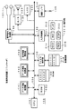
図12は、この第2の実施の形態の記録再生装置であるICレコーダを説明するためのブロック図である。この第2の実施の形態のICレコーダは、2つのマイクロホン131(1)、131(2)と、これら2つのマイクロホン131(1)、131(2)からの音声信号を処理する音声信号処理部136を備える点を除けば、図1に示した第1の実施の形態のICレコーダと同様に構成されるものである。このため、この第2の実施の形態のICレコーダにおいて、図1に示した第1の実施の形態のICレコーダと同様に構成される部分には同じ参照符号を付し、その部分の詳細な説明については省略することとする。
[Second Embodiment]
[Outline of configuration and operation of IC recorder]
FIG. 12 is a block diagram for explaining an IC recorder which is a recording / reproducing apparatus according to the second embodiment. The IC recorder of the second embodiment includes two microphones 131 (1) and 131 (2) and an audio signal processing unit that processes audio signals from the two microphones 131 (1) and 131 (2). Except for the point provided with 136, it is configured in the same manner as the IC recorder of the first embodiment shown in FIG. For this reason, in the IC recorder of the second embodiment, the same reference numerals are given to the same components as those of the IC recorder of the first embodiment shown in FIG. The description will be omitted.
そして、この第2の実施の形態のICレコーダにおいては、2つのマイクロホン131(1)、131(2)のそれぞれからの集音音声信号を音声信号処理部136において処理することにより、話者の位置(音源の位置)を特定するようにし、これをも考慮して集音した音声信号の変化点(話者の変化点)を特定することができるようにしたものである。すなわち、音声解析の結果得られる声紋データを用いた集音音声信号の変化点検出を行う場合の補助情報として、2つのマイクロホンの集音音声に基づく、話者の位置をも用いて、より正確に、変化点や話者を特定することができるようにしたものである。
In the IC recorder according to the second embodiment, the voice
図13は、マイクロホン131(1)、131(2)と、音声信号処理部136との構成例を説明するための図である。この図13に示す例の場合、2つのマイクロホン131(1)、131(2)のそれぞれは、図13にそれらの指向特性を示したように、いずれも単一指向性のものである。そして、マイクロホン131(1)、131(2)は、主指向方向が逆向きとなるように背中あわせに近接配置されている。これにより、マイクロホン131(1)は発言者Aの音声を良好に集音し、マイクロホン131(2)は発言者Bの音声を良好に集音することができるようにされる。
FIG. 13 is a diagram for explaining a configuration example of the microphones 131 (1) and 131 (2) and the audio
そして、音声信号処理部136は、図13に示したように、加算器1361と、コンパレータ(比較器)1362と、A/Dコンバータ1363とを備えたものである。そして、マイクロホン131(1)、131(2)のそれぞれ集音された音声信号は、加算器1361と、コンパレータ1362に供給される。
The audio
加算器1361は、マイクロホン131(1)からの集音音声信号と、マイクロホン131(2)からの集音音声信号とを加算し、加算後の音声信号をA/Dコンバータ1363に供給する。マイクロホン131(1)からの集音音声とマイクロホン131(2)からの集音音声の加算信号は、次の(式1)のように表すことがで、無指向性マイクで集音したものと同じになることが分かる。
((1+cosθ)/2)+((1−cosθ)/2)=1 …(1式)
また、コンパレータ1362は、マイクロホン131(1)からの集音声信号と、マイクロホン131(2)からの集音音声信号とを比較する。そして、コンパレータ1362は、マイクロホン131(1)からの集音音声信号のレベルの方が大きければ、発言者Aが主に発言していると判断し、値が「1(ハイレベル)」となる話者判別信号を制御部100に供給する。また、コンパレータ1362は、マイクロホン131(2)からの集音音声信号のレベルの方が大きければ、発言者Bが主に発言していると判断し、値が「0(ローレベル)」となる話者判別信号を制御部100に供給する。
The
((1 + cos θ) / 2) + ((1-cos θ) / 2) = 1 (Expression 1)
Further, the
これにより、マイクロホン131(1)からの集音音声信号と、マイクロホン131(2)からの集音音声信号とに基づいて、話者の位置を特定するようにし、発言者Aの発言か発言者Bの発言かを判別することができるようにしている。 Thus, the position of the speaker is specified based on the collected sound signal from the microphone 131 (1) and the collected sound signal from the microphone 131 (2), and the speaker A speaks or speaks. It is possible to determine whether the message is B.
なお、3人目の発言者Cが、マイクロホン131(1)、131(2)の主指向方向と交差する方向(図13において、発言者A、発言者Bをそれぞれ斜め前方に見る位置(図13の横方向))から発言した場合には、マイクロホン131(1)、131(2)からの集音音声の出力レベルはほぼ等しくなる。 Note that the third speaker C sees the speaker A and the speaker B obliquely forward in the direction crossing the main direction of the microphones 131 (1) and 131 (2) (FIG. 13). )), The output levels of the collected sound from the microphones 131 (1) and 131 (2) are substantially equal.
このような位置にある発言者Cについても対応する場合には、コンパレータ1362における閾値を2つ設けて、レベル差が±Vth以内なら横方向にいる発言者Cによる発言であると判断し、レベル差が+Vthより大きければ発言者Aであり、レベル差が−Vthより小さければ発言者Bであると判断するようにしてもよい。
When the speaker C at such a position is also supported, two threshold values in the
そして、マイクロホン131(1)の指向方向に位置する発言者、マイクロホン131(2)の指向方向に位置する発言者、マイクロホン131(1)、131(2)の指向方向と交差する方向に位置する発言者のそれぞれが誰であるかを把握しておくことにより、発言者(話者)が誰であるかを識別することができるようにされる。したがって、集音音声の特徴解析の結果得られる声紋データによる変化点検出の他に、マイクロホンの集音音声のレベルをも考慮することにより、発言者の特定をより正確に行うようにすることができる。 Then, a speaker located in the directivity direction of the microphone 131 (1), a speaker located in the directivity direction of the microphone 131 (2), and a direction intersecting the directivity direction of the microphones 131 (1) and 131 (2). By knowing who each of the speakers is, it is possible to identify who the speaker (speaker) is. Therefore, in addition to detection of change points based on voiceprint data obtained as a result of collected voice feature analysis, it is possible to more accurately identify the speaker by taking into account the level of the collected voice of the microphone. it can.
[マイクロホンと音声信号処理部の他の例]
また、マイクロホン131(1)、131(2)と音声信号処理部136とは、図14に示すように構成することもできる。すなわち、図14は、マイクロホン131(1)、131(2)と、音声信号処理部136との他の構成例を説明するための図である。この図14に示す例の場合、2つのマイクロホン131(1)、131(2)のそれぞれは、図14にそれらの指向特性を示したように、いずれも無指向性のものである。マイクロホン131(1)、131(2)は、例えば1cm位離間して近接配置するようにする。
[Other examples of microphone and audio signal processor]
Further, the microphones 131 (1) and 131 (2) and the audio
また、図14に示したように、この例の音声信号処理部136は、加算器1361、A/Dコンバータ1363、減算器1364、位相比較器1365を備えたものである。そして、マイクロホン131(1)、131(2)のそれぞれからの集音音声信号は、加算器1361と減算器1364とのそれぞれに供給される。
As shown in FIG. 14, the audio
ここで、加算器1361からの加算出力信号は、無指向性マイク出力と等価であり、減算器1364からの減算出力は、両指向性(8の字型指向性)マイク出力と等価である。両指向性マイクは、その音波の入射方向により出力の位相が正相または逆相になる。そこで、加算器1361からの加算出力(無指向性出力)と、減算器1364からの減算出力との間で位相コンパレータ1365により位相比較を行うことにより、減算器1364からの減算出力の極性を判断することにより発言者を特定できる。
Here, the added output signal from the
すなわち、減算器1364からの減算出力の極性が正相の場合には、発言者Aの発言を集音しており、減算器1364からの減算出力の極性が逆相の場合には、発言者Bの発言を集音していると判断することができる。
That is, when the polarity of the subtraction output from the
また、図13を用いて説明した場合と同様に、発言者A、発言者Bのそれぞれを斜め前方に見る位置(図14の横方向)に位置する発言者Cの発言をも判断しようとする場合には、当該発言者Cの発言を集音した音声信号の減算出力は、そのレベルが小さくなる。そこで、加算器1361からの加算出力と、減算器1364からの減算出力とのレベルをチェックすることで、発言者Cの発言をも認識することが可能となる。
Similarly to the case described with reference to FIG. 13, it also tries to determine the utterance of the utterer C located at the position where the utterer A and the utterer B are seen obliquely forward (lateral direction in FIG. 14). In this case, the level of the subtraction output of the audio signal obtained by collecting the utterance of the utterer C becomes small. Therefore, by checking the levels of the addition output from the
なお、図14に示した音声信号処理部136の場合には、加算器1361を用いるようにした。しかし、加算器1361は必須の構成要素ではない。例えば、マイクロホン131(1)、または、131(2)のいずれか一方の出力信号を、A/Dコンバータ1363と、位相比較器1365とに供給するようにしてもよい。
In the case of the audio
このように、図13、図14は、録音処理時において、2つのマイクロホン131(1)、131(2)の集音音声のレベルや極性を用いて、発言者の位置を特定することができるようにしている。そして、この特定結果をも考慮することにより、集音音声の変化点の検出、および、発言者の特定を精度良く行うことができるようにしている。 As described above, in FIGS. 13 and 14, the position of the speaker can be specified using the levels and polarities of the collected voices of the two microphones 131 (1) and 131 (2) during the recording process. I am doing so. By taking this identification result into consideration, it is possible to accurately detect the change point of the collected sound and to identify the speaker.
そして、図13、図14を用いた方式は、録音処理時だけでなく、再生処理時に録音音声に対してマークを付与する場合や、録音音声に対してマーク付与処理だけを独立に行う場合にも利用することができる。 The method using FIG. 13 and FIG. 14 is used not only at the time of the recording process but also when a mark is given to the recorded sound at the time of the reproduction process, or when only the mark giving process is performed on the recorded sound independently. Can also be used.
例えば、図13を用いて説明した方式を録音処理後において利用しようとする場合に置いては、図15Aに示すように、単一指向性のマイクロホン131(1)、131(2)のそれぞれからの集音音声信号を2チャンネルステレオ録音する。そして、図15Bに示すように、再生時、あるいは、マーク付与処理を独立に行う場合において、外部記憶装置111から読み出されるデータ圧縮された2チャンネルの音声信号のそれぞれを伸張処理し、伸張処理後の2チャンネルの音声信号を図13に示したコンパレータ1362と同様の機能を有するコンパレータに入力する。
For example, when the system described with reference to FIG. 13 is to be used after recording processing, as shown in FIG. 15A, each of the unidirectional microphones 131 (1) and 131 (2) is used. 2 channel stereo recording of the collected audio signal. Then, as shown in FIG. 15B, during reproduction or when the mark providing process is performed independently, each of the compressed two-channel audio signals compressed from the
これにより、マイクロホン131(1)の集音音声信号が主に用いられたか、マイクロホン131(2)の集音音声信号が主に用いられたかを判別することができ、この判別結果と、予め把握されている各マイクロホンに対する発言者の位置とに基づいて、発言者を特定することができる。 This makes it possible to determine whether the collected sound signal of the microphone 131 (1) is mainly used or whether the collected sound signal of the microphone 131 (2) is mainly used. The speaker can be specified based on the position of the speaker with respect to each microphone.
なお、図14を用いて説明した方式を録音処理後において利用しようとする場合においても同様に、マイクロホン131(1)、131(2)からの出力信号を2チャンネルステレオ録音し、再生時やマーク付与処理を独立に行う場合において、図14に示した音声信号処理部136と同様の処理を行うことによって、発言者を特定することができる。
Similarly, when the method described with reference to FIG. 14 is to be used after the recording process, the output signals from the microphones 131 (1) and 131 (2) are recorded in two channels in stereo, and are reproduced or marked. In the case where the assigning process is performed independently, the speaker can be specified by performing the same process as the audio
そして、マイクロホン131(1)、131(2)からの出力信号を用いた発言者の特定処理を行う場合に予め用意するマイクロホン131(1)、131(2)のそれぞれに対する発言者の位置情報は、例えば、図16に示す話者位置データベースのようにして、ICレコーダに記憶保持されておくようにすればよい。 The position information of the speaker with respect to each of the microphones 131 (1) and 131 (2) prepared in advance when performing speaker specifying processing using output signals from the microphones 131 (1) and 131 (2) is as follows. For example, it may be stored and held in the IC recorder as in the speaker position database shown in FIG.
図16は、話者位置データベースの一例を説明するための図である。この例の話者位置データベースは、ICレコーダの音声信号処理部136からの識別結果に対応する話者識別信号と、各話者識別信号に対応するマイクロホンの識別情報と、各マイクロホンを主に用いる発言者候補の識別子(話者識別子)からなるものである。また、図16に示したように、1つのマイクロホンに対して、話者識別子は複数個登録することができるようにしている。
FIG. 16 is a diagram for explaining an example of the speaker position database. The speaker position database in this example mainly uses the speaker identification signal corresponding to the identification result from the audio
この図16に示すような話者位置データベースは、好ましくは、会議の始まる前に作成しておく。一般に、会議への出席者や各出席者の席順は予め決まっている場合が多いので、ICレコーダの設置位置を考慮して、会議の始まる前に話者位置データベースを作成することが可能である。 The speaker location database as shown in FIG. 16 is preferably created before the start of the conference. In general, there are many cases where attendees to a conference and the seating order of each attendee are determined in advance, so that it is possible to create a speaker location database before the start of the conference in consideration of the installation position of the IC recorder. .
また、会議への出席者の急な変更や、会議中において、座席が変更になった場合においては、例えば、マイクロホンの集音音声に応じた発言者の認識は行わないようにし、音声解析処理により得た声紋データによる変化点の検出だけを行うようにしたり、あるいは、録音処理後において、話者位置データベースを調整して正確なものとし、録音音声に対して、マークの付け直しを行うようにしたりすることもできる。 Also, if the attendees suddenly change or the seat changes during the meeting, for example, the speaker is not recognized according to the sound collected by the microphone, and voice analysis processing is performed. Only the change point is detected based on the voiceprint data obtained from the above, or after the recording process, the speaker position database is adjusted to be accurate and the recorded voice is remarked. It can also be made.
この図16に示すような話者位置データベースを用いることにより、話者位置を特定し、その位置の話者自体をも特定することができるようにされる。 By using the speaker position database as shown in FIG. 16, the speaker position can be specified, and the speaker itself at that position can also be specified.
なお、この第2の実施の形態においては、2つのマイクロホン131(1)、131(2)を用い、発言者も2人または3人である場合を例にして説明したが、これに限るものではない。用いるマイクロホンを多くすることにより、より多くの発言者の識別を行うことが可能である。 In the second embodiment, the case where two microphones 131 (1) and 131 (2) are used and the number of speakers is two or three has been described as an example. However, the present invention is not limited to this. is not. By using more microphones, it is possible to identify more speakers.
また、マイクロホンからの出力信号に応じて、発言者の位置を特定することにより、発言者自身を特定する方式としては、図13、図14を用いて説明した方式に限るものではない。例えば、近接4点法や近接3点法などを用いるようにすることもできる。 Further, the method of specifying the speaker himself / herself by specifying the position of the speaker according to the output signal from the microphone is not limited to the method described with reference to FIGS. For example, a proximity 4-point method or a proximity 3-point method can be used.
近接4点法は、図17Aに示すように、必ず1つのマイクロホンが同一平面内にないようにして近接配置される4つのマイクロホンM0、M1、M2、M3で集音された音声信号の時間構造のわずかな違いに着目して、短時間相関あるいはインテンシティなどの手法により、音源の位置や大きさなどの空間情報を算出するようにする手法である。このように、少なくとも4つのマイクロホンを用いることにより、発言者の位置を性格に特定し、その発言者の位置(座席位置)に応じて、発言者を特定することも可能である。 As shown in FIG. 17A, the proximity four-point method is a time structure of audio signals collected by four microphones M0, M1, M2, and M3 that are arranged in close proximity so that one microphone is not necessarily in the same plane. In this method, spatial information such as the position and size of the sound source is calculated by a technique such as short-time correlation or intensity. Thus, by using at least four microphones, it is possible to specify the position of the speaker in a personality and to specify the speaker according to the position (seat position) of the speaker.
また、発言者がほぼ水平面内に位置すると限定して差し支えない場合には、近接配置されるマイクロホンの配置関係は、図17Bに示すように水平面内の3つでよい。 Further, in the case where it is possible to limit the speaker to be located substantially in the horizontal plane, the arrangement relationship of the microphones arranged close to each other may be three in the horizontal plane as shown in FIG. 17B.
また、図17A、Bに示したように、各マイクロホンの配置関係は、直交関係とならなくてもよい。図17Bに示した近接3点法の場合には、3つのマイクロホンが、例えば正三角形の頂点に配置されるような位置関係となるようにしてもよい。 As shown in FIGS. 17A and 17B, the arrangement relationship of the microphones does not have to be an orthogonal relationship. In the case of the proximity three-point method shown in FIG. 17B, the three microphones may have a positional relationship such as being arranged at the apex of an equilateral triangle, for example.
[第2の実施の形態の変形例]
上述した第2の実施の形態のICレコーダにおいては、音声解析の結果得られる声紋データを用いた集音音声信号の変化点検出を行う場合に、2つのマイクロホンの集音音声に基づく、主に利用されているマイクロホンの判別結果をも考慮することによって、音声信号の変化点の検出をより精度良く行うようにした。しかし、これに限るものではない。
[Modification of Second Embodiment]
In the above-described IC recorder of the second embodiment, when detecting a change point of a collected sound signal using voiceprint data obtained as a result of sound analysis, mainly based on the collected sound of two microphones. By taking into account the discrimination results of the microphones used, the change point of the audio signal is detected with higher accuracy. However, it is not limited to this.
例えば、図18に示すように、2つのマイクロホン131(1)、131(2)と、音声信号処理部136は備えるが、音声特徴解析部143を備えないようにしたICレコーダを構成することも可能である。すなわち、図18のICレコーダは、音声特徴解析部143を備えない点を除けば、図12に示した第2の実施の形態のICレコーダと同様に構成されるものである。
For example, as shown in FIG. 18, an IC recorder may be configured in which two microphones 131 (1) and 131 (2) and an audio
そして、2つのマイクロホン131(1)、131(2)の集音音声に基づく、主に利用されているマイクロホンの判別結果のみに基づいて、話者の変化点を検出し、その変化点に応じた音声信号上の対応する位置にマークを付すようにすることもできる。このようにした場合には、音声特徴解析処理を行う必要が無いので、CPU101にかかる負荷を軽減することができる。
Then, based on the collected sound of the two microphones 131 (1) and 131 (2), the change point of the speaker is detected based only on the discrimination result of the microphone that is mainly used, and according to the change point. It is also possible to add a mark to the corresponding position on the audio signal. In this case, since it is not necessary to perform the voice feature analysis process, the load on the
なお、上述した実施の形態においては、処理対象の音声信号の変化点にマークを付すようにしたが、変化点であっても、話音声への変化点のみにマークを付すようにすることによって、より効率的に検索を行うようにすることができる。例えば、処理対象の音声信号の信号レベルや声紋データなどに基づいて、話音声とそれ以外の雑音などの不要部分とを明確に認識するようにし、話音声の開始点のみにマークを付すようにすることもできる。 In the above-described embodiment, a mark is attached to the change point of the processing target audio signal. However, even if it is a change point, the mark is attached only to the change point to the spoken voice. , You can make the search more efficient. For example, based on the signal level or voiceprint data of the processing target speech signal, the speech and other unnecessary parts such as noise are clearly recognized, and only the start point of the speech is marked. You can also
また、声紋データや音声信号の周波数の特徴データなどに基づいて、話者が男性か女性かを判別して、変化点における話者の性別を通知するようにすることも可能である。 It is also possible to determine whether the speaker is male or female based on voiceprint data, frequency characteristic data of the audio signal, etc., and to notify the gender of the speaker at the changing point.
また、上述したように付されるマーク情報に基づいて、検索だけを行う用にする検索モードや、付されたマークの位置を変更したり、削除したり、追加したりするマーク編集モードや、また、付されたマークに応じて指定可能な話者の発言部分のみ、例えば、Aさんの発言部分のみを再生するようにする特殊再生モードなどを設けるようにすることもできる。これらの各モードの実現は、CPU101で実行するプログラムに追加のみによって比較的に簡単に実現可能である。
In addition, based on the mark information attached as described above, a search mode for performing only a search, a mark edit mode for changing, deleting, or adding a position of the attached mark, It is also possible to provide a special reproduction mode for reproducing only the utterance portion of the speaker that can be specified according to the mark, for example, only the utterance portion of Mr. A. Each of these modes can be realized relatively easily only by adding to the program executed by the
また、図6に示した音声特徴データベースの声紋データを、変化点の検出に用いた声紋データによって更新し、精度の高い音声特徴データベースにするなど、データベースの更新機能を持たせるようにしてもよい。例えば、声紋データの比較処理において不一致であっても、実際にその発言者の音声特徴データベースが存在している場合には、その発言者のデータベースの声紋データを新たに取得した声紋データに変更するようにすることができる。 In addition, the voice print data in the voice feature database shown in FIG. 6 may be updated with the voice print data used for detecting the change point to obtain a highly accurate voice feature database. . For example, even if there is a mismatch in the voice print data comparison process, if the voice feature database of the speaker is actually present, the voice print data of the speaker database is changed to the newly acquired voice print data. Can be.
また、声紋データの比較処理において一致しても、実際には違う話者の声紋データと一致してしまうような場合には、その異なる話者の声紋データを比較処理に用いないように設定するなどのこともできる。 In addition, if the voiceprint data is matched in the voiceprint data comparison process but actually matches the voiceprint data of a different speaker, the voiceprint data of the different speaker is set not to be used in the comparison process. You can also.
また、声紋データが、複数の話者の声紋データと一致してしまうような場合には、正しい話者とだけ一致するように、用いる声紋データに優先順位を付けるようにしてももちろんよい。 In addition, when the voiceprint data matches the voiceprint data of a plurality of speakers, the voiceprint data to be used may be prioritized so as to match only the correct speaker.
また、マークを付す位置は、発言の開始点だけでなく、終了点に付すようにしてもよいし、その他、開始点から数秒後または数秒前などのユーザ個々の利便性を考慮して、変更できるようにすることも可能である。 In addition, the position where the mark is added may be added not only to the start point of the speech but also to the end point, and may be changed in consideration of the convenience of each user such as several seconds or several seconds before the start point. It is also possible to make it possible.
また、音声信号の特徴解析は、上述もしたように、声紋解析だけでなく、種々の方法の1つ以上を用いることにより、精度の高い解析データを得るようにすることができる。 In addition, as described above, the feature analysis of the audio signal can obtain highly accurate analysis data by using not only the voice print analysis but also one or more of various methods.
また、上述した第2の実施の形態においては、主に2つのマイクロホンを用いた場合を例にして説明したが、これに限るものではない。マイクロホンの数は2つ以上であれば、いくつでも良く、それら複数のマイクロホンの個々の集音音声の信号レベル、極性、また、集音までの遅延時間などの種々のパラメータを利用して、話者の位置を特定し、その位置に応じた話者自身を特定できるようにすることができる。 In the above-described second embodiment, the case where two microphones are mainly used has been described as an example, but the present invention is not limited to this. As long as the number of microphones is two or more, any number of microphones may be used. By using various parameters such as the signal level, polarity, and delay time until sound collection of each of the plurality of microphones. The position of the speaker can be specified, and the speaker himself can be specified according to the position.
また、上述した第1、第2の実施の形態においては、音声信号の記録再生装置であるICレコーダにこの発明を適用した場合を例にして説明したが、これに限るものではない。例えば、ハードディスクドライブやMDなどの光磁気ディスク、DVDなどの光ディスクなどの記録媒体を用いる記録装置、再生装置、記録再生装置にこの発明を適用することができる。すなわち、種々の記録媒体を用いる記録装置、再生装置、記録再生装置にこの発明を適用することが可能である。 In the first and second embodiments described above, the case where the present invention is applied to an IC recorder that is a recording / reproducing apparatus for audio signals has been described as an example. However, the present invention is not limited to this. For example, the present invention can be applied to a recording apparatus, a reproducing apparatus, and a recording / reproducing apparatus that use a recording medium such as a hard disk drive or a magneto-optical disk such as an MD or an optical disk such as a DVD. That is, the present invention can be applied to a recording apparatus, a reproducing apparatus, and a recording / reproducing apparatus that use various recording media.
[ソフトウエアによる実現]
また、上述した実施の形態のICレコーダの音声特徴解析部143、音声信号処理部136などの各処理部の機能を実現するようにすると共に、各機能を有機的に結びつけるようにするプログラムを作成し、このプログラムをCPU101において実行するようにすることによっても、この発明を実現することができる。すなわち、図4、図5のフローチャートに示した処理を行うプログラムを作成し、これをCPU101で実行させることにより、この発明を実現することができる。
[Realization by software]
Also, a program for realizing the functions of each processing unit such as the audio
また、上述した実施の形態と同様に、例えば音声特徴解析部143の機能を実現したプログラムがインストールされたパーソナルコンピュータに、録音機で録音した音声データを取り込み、話者の切り換わりを検出させることも可能である。
Similarly to the above-described embodiment, for example, the personal computer installed with the program that implements the function of the voice
101…CPU、102…ROM、103…RAM、104…CPUバス、110…ファイル処理部、111…データ記憶装置、120…入力処理部、121…キー操作部、132…A/Dコンバータ、131…マイクロホン、134…D/Aコンバータ、133…スピーカ、135…LCD、141…データ圧縮処理部、142…データ伸張処理部、143…音声特徴解析部、144…通信I/F、145…接続端子、131(1)、131(2)…マイクロホン、136…音声信号処理部
DESCRIPTION OF
Claims (30)
前記検出手段により話者が変化したと検出された前記音声信号上の位置を示す変化点情報を取得する取得手段と、
前記取得手段により取得された前記変化点情報を保持する保持手段と
を備えることを特徴とする音声信号処理装置。 Detecting means for detecting, for each predetermined processing unit, a change in speaker of the audio signal based on the audio signal to be processed;
Acquisition means for acquiring change point information indicating a position on the audio signal detected by the detection means as a speaker has changed;
An audio signal processing apparatus comprising: holding means for holding the change point information acquired by the acquisition means.
前記検出手段は、前記処理単位毎に前記音声信号の特徴を抽出し、抽出した前記音声信号の特徴に基づいて、話音声以外の部分から話音声部分への変化点、および、話音声部分の話者の変化点を検出することができるものであることを特徴とする音声信号処理装置。 The audio signal processing apparatus according to claim 1,
The detection means extracts features of the audio signal for each processing unit, and based on the extracted features of the audio signal, a change point from a portion other than the spoken voice to a spoken voice portion, and A voice signal processing apparatus capable of detecting a change point of a speaker.
1人以上の話者の話音声の特徴を示す特徴情報と前記話者の識別情報とを対応付けて記憶保持する記憶手段と、
前記検出手段により抽出された前記音声信号の前記特徴と、前記記憶手段に記憶保持されている前記特徴情報とを比較して、話者を特定する特定手段と
を備え、
前記保持手段は、前記変化点情報と、前記特定手段で特定された話者の前記識別情報とを関連付けて保持することを特徴とする音声信号処理装置。 The audio signal processing device according to claim 2,
Storage means for storing and holding feature information indicating features of speech of one or more speakers and the identification information of the speakers in association with each other;
A means for specifying a speaker by comparing the feature of the voice signal extracted by the detection means with the feature information stored and held in the storage means; and
The holding means holds the change point information and the identification information of the speaker specified by the specifying means in association with each other.
複数のマイクロホンのそれぞれに対応する複数の音声チャンネルの音声信号を解析して話者位置を検出する第2の検出手段を備え、
前記取得手段は、前記第2の検出手段により検出された話者位置の変化をも考慮して、前記変化点を特定し、特定した変化点に対応する前記変化点情報を取得することを特徴とする音声信号処理装置。 The audio signal processing device according to claim 2,
Second detection means for detecting a speaker position by analyzing audio signals of a plurality of audio channels corresponding to each of the plurality of microphones;
The acquisition unit specifies the change point in consideration of a change in speaker position detected by the second detection unit, and acquires the change point information corresponding to the specified change point. An audio signal processing device.
複数のマイクロホンのそれぞれに対応する複数の音声チャンネルの音声信号に応じて決められる話者位置と、前記話者位置の話者の識別情報とを対応付けて記憶保持する話者情報記憶手段と、
前記複数の音声チャンネルの音声信号を解析して得られる前記話者位置に応じた話者の前記識別情報を前記話者情報保持手段から取得する話者情報取得手段と
を備え、
前記特定手段は、前記話者情報取得手段により取得された話者の前記識別情報をも考慮して、前記話者を特定することを特徴とする音声信号処理装置。 The audio signal processing device according to claim 3,
Speaker information storage means for storing and holding a speaker position determined in accordance with audio signals of a plurality of audio channels corresponding to each of a plurality of microphones and identification information of the speaker at the speaker position in association with each other;
Speaker information acquisition means for acquiring, from the speaker information holding means, the identification information of the speaker corresponding to the speaker position obtained by analyzing audio signals of the plurality of audio channels;
The audio signal processing apparatus characterized in that the specifying means specifies the speaker in consideration of the identification information of the speaker acquired by the speaker information acquisition means.
前記記憶手段には、各識別情報に対応する話者に関連する情報が各識別情報に対応付けられて記憶されており、
前記音声信号に対する変化点の位置と前記話者に関連する情報とを表示する表示情報処理手段を備えることを特徴とする音声信号処理装置。 The audio signal processing apparatus according to claim 3 or 5, wherein
In the storage means, information related to a speaker corresponding to each identification information is stored in association with each identification information,
An audio signal processing apparatus comprising display information processing means for displaying a position of a change point with respect to the audio signal and information related to the speaker.
前記検出手段は、異なるマイクロホンにより集音される各音声チャンネルの音声信号を解析することにより得られる話者位置に基づいて、前記話者の変化を検出するものであることを特徴とする音声信号処理装置。 The audio signal processing apparatus according to claim 1,
The detection means detects the change of the speaker based on the speaker position obtained by analyzing the audio signal of each audio channel collected by a different microphone. Processing equipment.
前記保持手段は、前記変化点情報と、前記検出手段により検出される話者位置を示す情報とを関連付けて保持することを特徴とする音声信号処理装置。 The audio signal processing device according to claim 7,
The holding means holds the change point information and information indicating a speaker position detected by the detecting means in association with each other.
複数のマイクロホンのそれぞれに対応する複数の音声チャンネルの音声信号に応じて決められる話者位置と、前記話者位置の話者の識別情報とを対応付けて記憶保持する話者情報記憶手段と、
前記複数の音声チャンネルのそれぞれの音声信号を解析して得られる前記話者位置に応じた話者の前記識別情報を前記話者情報保持手段から取得する話者情報取得手段と
を備え、
前記保持手段は、前記変化点情報と、前記話者情報取得手段により取得された話者の前記識別情報とを関連付けて保持することを特徴とする音声信号処理装置。 The audio signal processing device according to claim 7,
Speaker information storage means for storing and holding a speaker position determined in accordance with audio signals of a plurality of audio channels corresponding to each of a plurality of microphones and identification information of the speaker at the speaker position in association with each other;
Speaker information acquisition means for acquiring the identification information of the speaker according to the speaker position obtained by analyzing the respective audio signals of the plurality of audio channels from the speaker information holding means,
The audio signal processing apparatus, wherein the holding unit holds the change point information and the identification information of the speaker acquired by the speaker information acquisition unit in association with each other.
前記話者情報記憶手段には、各識別情報に対応する話者に関連する情報が各識別情報に対応付けられて記憶されており、
前記音声信号に対する変化点の位置と前記話者に関連する情報とを表示する表示情報処理手段を備えることを特徴とする音声信号処理装置。 The audio signal processing device according to claim 9,
In the speaker information storage means, information related to a speaker corresponding to each identification information is stored in association with each identification information,
An audio signal processing apparatus comprising display information processing means for displaying a position of a change point with respect to the audio signal and information related to the speaker.
前記検出ステップにおいて、話者が変化したと検出した前記音声信号上の位置を示す変化点情報を取得する取得ステップと、
前記取得ステップにおいて取得した前記変化点情報を記録媒体に格納する格納ステップと
を有することを特徴とする音声信号処理方法。 A detection step of detecting, for each predetermined processing unit, a change in speaker of the audio signal based on the audio signal to be processed;
In the detection step, an acquisition step of acquiring change point information indicating a position on the audio signal detected as a speaker has changed,
An audio signal processing method comprising: a storage step of storing the change point information acquired in the acquisition step in a recording medium.
前記検出ステップにおいては、前記処理単位毎に前記音声信号の特徴を抽出し、抽出した前記音声信号の特徴に基づいて、話音声以外の部分から話音声部分への変化点、および、話音声部分の話者の変化点を検出することを特徴とする音声信号処理方法。 The audio signal processing method according to claim 11, comprising:
In the detection step, a feature of the audio signal is extracted for each processing unit, and a change point from a portion other than the spoken speech to a spoken speech portion based on the extracted feature of the speech signal, and a spoken speech portion A method of processing an audio signal, comprising detecting a change point of a speaker.
前記検出ステップにおいて抽出された前記音声信号の前記特徴と、1人以上の話者の話音声の特徴を示す特徴情報と前記話者の識別情報とが対応付けられて記憶されている記録媒体の前記特徴情報とを比較して話者を特定する特定ステップを有し、
前記格納ステップにおいては、前記変化点情報と、前記特定ステップで特定した話者の前記識別情報とを関連付けて前記記録媒体に格納することを特徴とする音声信号処理方法。 An audio signal processing method according to claim 12, comprising:
A recording medium in which the features of the voice signal extracted in the detection step, feature information indicating features of speech speech of one or more speakers, and identification information of the speakers are stored in association with each other. A specific step of identifying a speaker by comparing with the feature information;
In the storage step, the change point information and the identification information of the speaker specified in the specifying step are associated with each other and stored in the recording medium.
複数のマイクロホンのそれぞれに対応する複数の音声チャンネルの音声信号を解析して話者位置を検出する第2の検出ステップを有し、
前記取得ステップにおいては、前記第2の検出ステップにおいて検出した話者位置の変化をも考慮して、前記変化点を特定し、特定した変化点に対応する前記変化点情報を取得することを特徴とする音声信号処理方法。 An audio signal processing method according to claim 12, comprising:
A second detection step of detecting a speaker position by analyzing voice signals of a plurality of voice channels corresponding to each of the plurality of microphones;
In the acquisition step, the change point is specified in consideration of the change in the speaker position detected in the second detection step, and the change point information corresponding to the specified change point is acquired. An audio signal processing method.
複数のマイクロホンのそれぞれに対応する複数の音声チャンネルの音声信号に応じて決められる話者位置と、前記話者位置の話者の識別情報とを対応付けて予め話者情報記憶手段に記憶保持する話者情報記憶ステップを設け、
前記複数の音声チャンネルの音声信号を解析して得られる話者位置に応じた話者の前記識別情報を前記話者情報記憶手段から取得する話者情報取得ステップを有し、
前記特定ステップにおいては、前記話者情報取得ステップにおいて取得した話者の前記識別情報をも考慮して、前記話者を特定することを特徴とする音声信号処理方法。 The audio signal processing method according to claim 13,
A speaker position determined according to audio signals of a plurality of audio channels corresponding to each of a plurality of microphones and the identification information of the speaker at the speaker position are associated with each other and stored in advance in the speaker information storage means. There is a speaker information storage step,
A speaker information acquisition step of acquiring the identification information of the speaker according to the speaker position obtained by analyzing the audio signals of the plurality of audio channels from the speaker information storage means;
In the specifying step, the speaker is specified in consideration of the identification information of the speaker acquired in the speaker information acquiring step.
前記記憶手段には、各識別情報に対応する話者に関連する情報が各識別情報に対応付けられて記憶されており、
前記音声信号に対する変化点の位置と前記話者に関連する情報とを表示する表示情報処理ステップを有することを特徴とする音声信号処理方法。 The audio signal processing method according to claim 13 or 15,
In the storage means, information related to a speaker corresponding to each identification information is stored in association with each identification information,
An audio signal processing method comprising: a display information processing step for displaying a position of a change point with respect to the audio signal and information related to the speaker.
前記検出ステップにおいては、異なるマイクロホンにより集音される各音声チャンネルの音声信号を解析することにより得られる話者位置に基づいて、前記変化点を検出することを特徴とする音声信号処理方法。 The audio signal processing method according to claim 11, comprising:
In the detecting step, the change point is detected based on a speaker position obtained by analyzing a sound signal of each sound channel collected by a different microphone.
前記格納ステップにおいては、前記変化点情報と、前記検出ステップにおいて検出される話者位置を示す情報とを関連付けて格納することを特徴とする音声信号処理方法。 The audio signal processing method according to claim 17,
In the storing step, the change point information and the information indicating the speaker position detected in the detecting step are stored in association with each other.
複数のマイクロホンのそれぞれに対応する複数の音声チャンネルの音声信号に応じて決められる話者位置と、前記話者位置の話者の識別情報とを対応付けて予め話者情報記憶手段に記憶保持する話者情報記憶ステップを設け、
前記複数の音声チャンネルの音声信号を解析して得られる話者位置に応じた話者の前記識別情報を前記話者情報記憶手段から取得する話者情報取得ステップを有し、
前記格納ステップにおいては、前記変化点情報と、前記話者情報取得ステップにおいて取得される話者の前記識別情報とを関連付けて格納することを特徴とする音声信号処理方法。 The audio signal processing method according to claim 17,
A speaker position determined according to audio signals of a plurality of audio channels corresponding to each of a plurality of microphones and the identification information of the speaker at the speaker position are associated with each other and stored in advance in the speaker information storage means. There is a speaker information storage step,
A speaker information acquisition step of acquiring the identification information of the speaker according to the speaker position obtained by analyzing the audio signals of the plurality of audio channels from the speaker information storage means;
In the storing step, the change point information and the identification information of the speaker acquired in the speaker information acquiring step are stored in association with each other.
前記話者情報記憶手段には、各識別情報に対応する話者に関連する情報が各識別情報に対応付けられて記憶されており、
前記音声信号に対する変化点の位置と前記話者に関連する情報とを表示する表示情報処理ステップを有することを特徴とする音声信号処理方法。 The audio signal processing method according to claim 19, comprising:
In the speaker information storage means, information related to a speaker corresponding to each identification information is stored in association with each identification information,
An audio signal processing method comprising: a display information processing step for displaying a position of a change point with respect to the audio signal and information related to the speaker.
処理対象の音声信号に基づいて、当該音声信号の話者の変化を所定の処理単位毎に検出する検出手段、
前記検出手段において、話者が変化したと検出した前記音声信号上の位置を示す変化点情報を取得する取得手段、
前記取得手段において取得した前記変化点情報を記録媒体に格納する格納手段
として機能させるための音声信号処理プログラム。 A computer mounted on an audio signal processing device that processes audio signals,
Detecting means for detecting a change of a speaker of the audio signal for each predetermined processing unit based on the audio signal to be processed;
In the detection means, an acquisition means for acquiring change point information indicating a position on the voice signal detected as a speaker has changed,
The audio signal processing program for functioning as a storage means for storing the change point information acquired by the acquisition means in a recording medium.
前記検出手段においては、前記処理単位毎に前記音声信号の特徴を抽出し、抽出した前記音声信号の特徴に基づいて、話音声以外の部分から話音声部分への変化点、および、話音声部分の話者の変化点を検出することを特徴とする音声信号処理プログラム。 The audio signal processing program according to claim 21,
In the detection means, the feature of the audio signal is extracted for each processing unit, and based on the extracted feature of the audio signal, a change point from a portion other than the spoken voice to a spoken voice portion, and a spoken voice portion A speech signal processing program for detecting a change point of a speaker.
前記検出手段において抽出された前記音声信号の前記特徴と、1人以上の話者の話音声の特徴を示す特徴情報と前記話者の識別情報とが対応付けられて記憶されている記録媒体の前記特徴情報とを比較して話者を特定する特定手段として機能させると共に、
前記格納手段においては、前記変化点情報と、前記特定手段で特定した話者の前記識別情報とを関連付けて前記記録媒体に格納することを特徴とする音声信号処理プログラム。 An audio signal processing program according to claim 22,
A recording medium in which the characteristics of the audio signal extracted by the detection means, characteristic information indicating the characteristics of the voice of one or more speakers, and identification information of the speakers are stored in association with each other. While functioning as a specifying means for specifying the speaker by comparing with the feature information,
In the storage means, the change point information and the identification information of the speaker specified by the specifying means are associated with each other and stored in the recording medium.
複数のマイクロホンのそれぞれに対応する複数の音声チャンネルの音声信号を解析して話者位置を検出する第2の検出手段として機能させると共に、
前記取得手段においては、前記第2の検出手段において検出した変化をも考慮して、前記変化点を特定し、特定した変化点に対応する前記変化点情報を取得することを特徴とする音声信号処理プログラム。 An audio signal processing program according to claim 22,
While functioning as a second detection means for detecting a speaker position by analyzing audio signals of a plurality of audio channels corresponding to each of a plurality of microphones,
The acquisition means specifies the change point in consideration of the change detected by the second detection means, and acquires the change point information corresponding to the specified change point. Processing program.
複数のマイクロホンのそれぞれに対応する複数の音声チャンネルの音声信号に応じて決められる話者位置と、前記話者位置の話者の識別情報とを対応付けて記憶保持する話者情報記憶手段を用いるようにし、
前記複数の音声チャンネルの音声信号を解析して得られる話者位置に応じた話者の前記識別情報を前記話者情報記憶手段から取得する話者情報取得手段として機能させると共に、
前記特定手段においては、前記話者情報取得手段において取得した話者の前記識別情報をも考慮して、前記話者を特定することを特徴とする音声信号処理プログラム。 An audio signal processing program according to claim 23,
Speaker information storage means for storing and holding a speaker position determined in accordance with audio signals of a plurality of audio channels corresponding to each of a plurality of microphones and identification information of the speaker at the speaker position in association with each other is used. And
While functioning as speaker information acquisition means for acquiring the identification information of the speaker according to the speaker position obtained by analyzing the audio signals of the plurality of audio channels from the speaker information storage means,
An audio signal processing program characterized in that the specifying means specifies the speaker in consideration of the identification information of the speaker acquired by the speaker information acquisition means.
前記記録媒体には、各識別情報に対応する話者に関連する情報が各識別情報に対応付けられて記憶されており、
前記音声信号に対する変化点の位置と前記話者に関連する情報とを表示する表示情報処理手段としての機能をも実効することを特徴とする音声信号処理プログラム。 An audio signal processing program according to claim 23 or claim 25,
In the recording medium, information related to a speaker corresponding to each identification information is stored in association with each identification information,
An audio signal processing program that also functions as display information processing means for displaying a position of a change point with respect to the audio signal and information related to the speaker.
前記検出手段においては、異なるマイクロホンにより集音される各音声チャンネルの音声信号のそれぞれを解析して得られる話者位置に応じて、前記変化点を検出することを特徴とする音声信号処理プログラム。 The audio signal processing program according to claim 21,
The audio signal processing program characterized in that the detecting means detects the change point according to a speaker position obtained by analyzing each audio signal of each audio channel collected by a different microphone.
前記格納手段においては、前記変化点情報と、前記検出ステップにおいて検出される話者位置を示す情報とを関連付けて格納することを特徴とする音声信号処理プログラム。 An audio signal processing program according to claim 27, wherein
The storage means stores the change point information and information indicating a speaker position detected in the detection step in association with each other.
複数のマイクロホンのそれぞれに対応する複数の音声チャンネルの音声信号に応じて決められる話者位置と、前記話者位置の話者の識別情報とを対応付けて記憶保持する話者情報記憶手段を用いるようにし、
前記複数の音声チャンネルの音声信号を解析して得られる前記話者位置に応じた話者の前記識別情報を前記話者情報記憶手段から取得する話者情報取得手段として機能させると共に、
前記格納手段においては、前記変化点情報と、前記話者情報取得手段において取得される話者の前記識別情報とを関連付けて格納することを特徴とする音声信号処理プログラム。 An audio signal processing program according to claim 27, wherein
Speaker information storage means for storing and holding a speaker position determined in accordance with audio signals of a plurality of audio channels corresponding to each of a plurality of microphones and identification information of the speaker at the speaker position in association with each other is used. And
While functioning as speaker information acquisition means for acquiring the identification information of the speaker according to the speaker position obtained by analyzing the audio signals of the plurality of audio channels from the speaker information storage means,
In the storage means, the change point information and the identification information of the speaker acquired in the speaker information acquisition means are stored in association with each other.
前記話者情報記憶手段には、各識別情報に対応する話者に関連する情報が各識別情報に対応付けられて記憶されており、
前記音声信号に対する変化点の位置と前記話者に関連する情報とを表示する表示情報処理手段としての機能をも実行することを特徴とする音声信号処理プログラム。 An audio signal processing program according to claim 29, wherein
In the speaker information storage means, information related to a speaker corresponding to each identification information is stored in association with each identification information,
An audio signal processing program that also executes a function as display information processing means for displaying a position of a change point with respect to the audio signal and information related to the speaker.
Priority Applications (4)
| Application Number | Priority Date | Filing Date | Title |
|---|---|---|---|
| JP2004006456A JP2005202014A (en) | 2004-01-14 | 2004-01-14 | Audio signal processor, audio signal processing method, and audio signal processing program |
| US11/036,533 US20050182627A1 (en) | 2004-01-14 | 2005-01-13 | Audio signal processing apparatus and audio signal processing method |
| KR1020050003281A KR20050074920A (en) | 2004-01-14 | 2005-01-13 | Sound signal processing apparatus and method thereof |
| CNB2005100601004A CN1333363C (en) | 2004-01-14 | 2005-01-14 | Audio signal processing apparatus and audio signal processing method |
Applications Claiming Priority (1)
| Application Number | Priority Date | Filing Date | Title |
|---|---|---|---|
| JP2004006456A JP2005202014A (en) | 2004-01-14 | 2004-01-14 | Audio signal processor, audio signal processing method, and audio signal processing program |
Related Child Applications (1)
| Application Number | Title | Priority Date | Filing Date |
|---|---|---|---|
| JP2007291765A Division JP2008102538A (en) | 2007-11-09 | 2007-11-09 | Storage/reproduction device and control method of storing/reproducing device |
Publications (1)
| Publication Number | Publication Date |
|---|---|
| JP2005202014A true JP2005202014A (en) | 2005-07-28 |
Family
ID=34820412
Family Applications (1)
| Application Number | Title | Priority Date | Filing Date |
|---|---|---|---|
| JP2004006456A Pending JP2005202014A (en) | 2004-01-14 | 2004-01-14 | Audio signal processor, audio signal processing method, and audio signal processing program |
Country Status (4)
| Country | Link |
|---|---|
| US (1) | US20050182627A1 (en) |
| JP (1) | JP2005202014A (en) |
| KR (1) | KR20050074920A (en) |
| CN (1) | CN1333363C (en) |
Cited By (8)
| Publication number | Priority date | Publication date | Assignee | Title |
|---|---|---|---|---|
| JP2008032825A (en) * | 2006-07-26 | 2008-02-14 | Fujitsu Fsas Inc | Speaker display system, speaker display method and speaker display program |
| JP2008102538A (en) * | 2007-11-09 | 2008-05-01 | Sony Corp | Storage/reproduction device and control method of storing/reproducing device |
| JP2008170588A (en) * | 2007-01-10 | 2008-07-24 | Kenwood Corp | Voice recording device and voice recording method |
| JP2010054733A (en) * | 2008-08-27 | 2010-03-11 | Nippon Telegr & Teleph Corp <Ntt> | Device and method for estimating multiple signal section, its program, and recording medium |
| JP2012090337A (en) * | 2012-01-13 | 2012-05-10 | Toshiba Corp | Electronic device and display processing method |
| US8935169B2 (en) | 2007-09-27 | 2015-01-13 | Kabushiki Kaisha Toshiba | Electronic apparatus and display process |
| JP2018106148A (en) * | 2016-12-12 | 2018-07-05 | ソリザバ カンパニー リミテッドSorizava Co., Ltd. | Multiplex speaker-speech-recognition correction system |
| JP7404568B1 (en) | 2023-01-18 | 2023-12-25 | Kddi株式会社 | Program, information processing device, and information processing method |
Families Citing this family (149)
| Publication number | Priority date | Publication date | Assignee | Title |
|---|---|---|---|---|
| US8645137B2 (en) | 2000-03-16 | 2014-02-04 | Apple Inc. | Fast, language-independent method for user authentication by voice |
| US9300790B2 (en) | 2005-06-24 | 2016-03-29 | Securus Technologies, Inc. | Multi-party conversation analyzer and logger |
| US8677377B2 (en) | 2005-09-08 | 2014-03-18 | Apple Inc. | Method and apparatus for building an intelligent automated assistant |
| US20070286358A1 (en) * | 2006-04-29 | 2007-12-13 | Msystems Ltd. | Digital audio recorder |
| JP2007318438A (en) * | 2006-05-25 | 2007-12-06 | Yamaha Corp | Voice state data generating device, voice state visualizing device, voice state data editing device, voice data reproducing device, and voice communication system |
| US9318108B2 (en) | 2010-01-18 | 2016-04-19 | Apple Inc. | Intelligent automated assistant |
| US20080256613A1 (en) * | 2007-03-13 | 2008-10-16 | Grover Noel J | Voice print identification portal |
| US8977255B2 (en) | 2007-04-03 | 2015-03-10 | Apple Inc. | Method and system for operating a multi-function portable electronic device using voice-activation |
| US9330720B2 (en) | 2008-01-03 | 2016-05-03 | Apple Inc. | Methods and apparatus for altering audio output signals |
| JP5156934B2 (en) * | 2008-03-07 | 2013-03-06 | 学校法人日本大学 | Acoustic measuring device |
| US8996376B2 (en) | 2008-04-05 | 2015-03-31 | Apple Inc. | Intelligent text-to-speech conversion |
| US10496753B2 (en) | 2010-01-18 | 2019-12-03 | Apple Inc. | Automatically adapting user interfaces for hands-free interaction |
| US20090313010A1 (en) * | 2008-06-11 | 2009-12-17 | International Business Machines Corporation | Automatic playback of a speech segment for media devices capable of pausing a media stream in response to environmental cues |
| WO2009153999A1 (en) * | 2008-06-20 | 2009-12-23 | 学校法人日本大学 | Acoustic energy measuring device, acoustic performance evaluation device utilizing same, and acoustic information measuring device |
| US20100030549A1 (en) | 2008-07-31 | 2010-02-04 | Lee Michael M | Mobile device having human language translation capability with positional feedback |
| DK2364495T3 (en) * | 2008-12-10 | 2017-01-16 | Agnitio S L | Method of verifying the identity of a speaking and associated computer-readable medium and computer |
| US9959870B2 (en) | 2008-12-11 | 2018-05-01 | Apple Inc. | Speech recognition involving a mobile device |
| US20100299131A1 (en) * | 2009-05-21 | 2010-11-25 | Nexidia Inc. | Transcript alignment |
| US9858925B2 (en) | 2009-06-05 | 2018-01-02 | Apple Inc. | Using context information to facilitate processing of commands in a virtual assistant |
| US10706373B2 (en) | 2011-06-03 | 2020-07-07 | Apple Inc. | Performing actions associated with task items that represent tasks to perform |
| US10241752B2 (en) | 2011-09-30 | 2019-03-26 | Apple Inc. | Interface for a virtual digital assistant |
| US10241644B2 (en) | 2011-06-03 | 2019-03-26 | Apple Inc. | Actionable reminder entries |
| US9431006B2 (en) | 2009-07-02 | 2016-08-30 | Apple Inc. | Methods and apparatuses for automatic speech recognition |
| CN102696239B (en) * | 2009-11-24 | 2020-08-25 | 诺基亚技术有限公司 | A device |
| US8560309B2 (en) * | 2009-12-29 | 2013-10-15 | Apple Inc. | Remote conferencing center |
| US10276170B2 (en) | 2010-01-18 | 2019-04-30 | Apple Inc. | Intelligent automated assistant |
| US10553209B2 (en) | 2010-01-18 | 2020-02-04 | Apple Inc. | Systems and methods for hands-free notification summaries |
| US10679605B2 (en) | 2010-01-18 | 2020-06-09 | Apple Inc. | Hands-free list-reading by intelligent automated assistant |
| US10705794B2 (en) | 2010-01-18 | 2020-07-07 | Apple Inc. | Automatically adapting user interfaces for hands-free interaction |
| WO2011102246A1 (en) * | 2010-02-18 | 2011-08-25 | 株式会社ニコン | Information processing device, portable device and information processing system |
| US8682667B2 (en) | 2010-02-25 | 2014-03-25 | Apple Inc. | User profiling for selecting user specific voice input processing information |
| US10762293B2 (en) | 2010-12-22 | 2020-09-01 | Apple Inc. | Using parts-of-speech tagging and named entity recognition for spelling correction |
| US9262612B2 (en) | 2011-03-21 | 2016-02-16 | Apple Inc. | Device access using voice authentication |
| US10057736B2 (en) | 2011-06-03 | 2018-08-21 | Apple Inc. | Active transport based notifications |
| US8994660B2 (en) | 2011-08-29 | 2015-03-31 | Apple Inc. | Text correction processing |
| US8879761B2 (en) | 2011-11-22 | 2014-11-04 | Apple Inc. | Orientation-based audio |
| US10134385B2 (en) | 2012-03-02 | 2018-11-20 | Apple Inc. | Systems and methods for name pronunciation |
| US9483461B2 (en) | 2012-03-06 | 2016-11-01 | Apple Inc. | Handling speech synthesis of content for multiple languages |
| US9280610B2 (en) | 2012-05-14 | 2016-03-08 | Apple Inc. | Crowd sourcing information to fulfill user requests |
| US9721563B2 (en) | 2012-06-08 | 2017-08-01 | Apple Inc. | Name recognition system |
| US10354650B2 (en) * | 2012-06-26 | 2019-07-16 | Google Llc | Recognizing speech with mixed speech recognition models to generate transcriptions |
| US9495129B2 (en) | 2012-06-29 | 2016-11-15 | Apple Inc. | Device, method, and user interface for voice-activated navigation and browsing of a document |
| US9576574B2 (en) | 2012-09-10 | 2017-02-21 | Apple Inc. | Context-sensitive handling of interruptions by intelligent digital assistant |
| US9547647B2 (en) | 2012-09-19 | 2017-01-17 | Apple Inc. | Voice-based media searching |
| JP2016508007A (en) | 2013-02-07 | 2016-03-10 | アップル インコーポレイテッド | Voice trigger for digital assistant |
| US9368114B2 (en) | 2013-03-14 | 2016-06-14 | Apple Inc. | Context-sensitive handling of interruptions |
| WO2014144579A1 (en) | 2013-03-15 | 2014-09-18 | Apple Inc. | System and method for updating an adaptive speech recognition model |
| KR101759009B1 (en) | 2013-03-15 | 2017-07-17 | 애플 인크. | Training an at least partial voice command system |
| WO2014197336A1 (en) | 2013-06-07 | 2014-12-11 | Apple Inc. | System and method for detecting errors in interactions with a voice-based digital assistant |
| US9582608B2 (en) | 2013-06-07 | 2017-02-28 | Apple Inc. | Unified ranking with entropy-weighted information for phrase-based semantic auto-completion |
| WO2014197334A2 (en) | 2013-06-07 | 2014-12-11 | Apple Inc. | System and method for user-specified pronunciation of words for speech synthesis and recognition |
| WO2014197335A1 (en) | 2013-06-08 | 2014-12-11 | Apple Inc. | Interpreting and acting upon commands that involve sharing information with remote devices |
| US10176167B2 (en) | 2013-06-09 | 2019-01-08 | Apple Inc. | System and method for inferring user intent from speech inputs |
| CN110442699A (en) | 2013-06-09 | 2019-11-12 | 苹果公司 | Operate method, computer-readable medium, electronic equipment and the system of digital assistants |
| CN105265005B (en) | 2013-06-13 | 2019-09-17 | 苹果公司 | System and method for the urgent call initiated by voice command |
| JP6163266B2 (en) | 2013-08-06 | 2017-07-12 | アップル インコーポレイテッド | Automatic activation of smart responses based on activation from remote devices |
| US9881605B2 (en) * | 2014-02-26 | 2018-01-30 | Mitsubishi Electric Corporation | In-vehicle control apparatus and in-vehicle control method |
| US9620105B2 (en) | 2014-05-15 | 2017-04-11 | Apple Inc. | Analyzing audio input for efficient speech and music recognition |
| US10592095B2 (en) | 2014-05-23 | 2020-03-17 | Apple Inc. | Instantaneous speaking of content on touch devices |
| US9502031B2 (en) | 2014-05-27 | 2016-11-22 | Apple Inc. | Method for supporting dynamic grammars in WFST-based ASR |
| US10289433B2 (en) | 2014-05-30 | 2019-05-14 | Apple Inc. | Domain specific language for encoding assistant dialog |
| US10170123B2 (en) | 2014-05-30 | 2019-01-01 | Apple Inc. | Intelligent assistant for home automation |
| US9715875B2 (en) | 2014-05-30 | 2017-07-25 | Apple Inc. | Reducing the need for manual start/end-pointing and trigger phrases |
| US9633004B2 (en) | 2014-05-30 | 2017-04-25 | Apple Inc. | Better resolution when referencing to concepts |
| US10078631B2 (en) | 2014-05-30 | 2018-09-18 | Apple Inc. | Entropy-guided text prediction using combined word and character n-gram language models |
| US9734193B2 (en) | 2014-05-30 | 2017-08-15 | Apple Inc. | Determining domain salience ranking from ambiguous words in natural speech |
| US9430463B2 (en) | 2014-05-30 | 2016-08-30 | Apple Inc. | Exemplar-based natural language processing |
| US9760559B2 (en) | 2014-05-30 | 2017-09-12 | Apple Inc. | Predictive text input |
| US9785630B2 (en) | 2014-05-30 | 2017-10-10 | Apple Inc. | Text prediction using combined word N-gram and unigram language models |
| US9842101B2 (en) | 2014-05-30 | 2017-12-12 | Apple Inc. | Predictive conversion of language input |
| US9966065B2 (en) | 2014-05-30 | 2018-05-08 | Apple Inc. | Multi-command single utterance input method |
| JP6340926B2 (en) * | 2014-06-09 | 2018-06-13 | 株式会社リコー | Information processing system, information processing apparatus, and program |
| US10659851B2 (en) | 2014-06-30 | 2020-05-19 | Apple Inc. | Real-time digital assistant knowledge updates |
| US9338493B2 (en) | 2014-06-30 | 2016-05-10 | Apple Inc. | Intelligent automated assistant for TV user interactions |
| KR102224568B1 (en) * | 2014-08-27 | 2021-03-08 | 삼성전자주식회사 | Method and Electronic Device for handling audio data |
| US10446141B2 (en) | 2014-08-28 | 2019-10-15 | Apple Inc. | Automatic speech recognition based on user feedback |
| KR101888391B1 (en) | 2014-09-01 | 2018-08-14 | 삼성전자 주식회사 | Method for managing audio signal and electronic device implementing the same |
| US9818400B2 (en) | 2014-09-11 | 2017-11-14 | Apple Inc. | Method and apparatus for discovering trending terms in speech requests |
| US10789041B2 (en) | 2014-09-12 | 2020-09-29 | Apple Inc. | Dynamic thresholds for always listening speech trigger |
| JP6509516B2 (en) * | 2014-09-29 | 2019-05-08 | Dynabook株式会社 | Electronic device, method and program |
| US10127911B2 (en) | 2014-09-30 | 2018-11-13 | Apple Inc. | Speaker identification and unsupervised speaker adaptation techniques |
| US9646609B2 (en) | 2014-09-30 | 2017-05-09 | Apple Inc. | Caching apparatus for serving phonetic pronunciations |
| US9668121B2 (en) | 2014-09-30 | 2017-05-30 | Apple Inc. | Social reminders |
| US9886432B2 (en) | 2014-09-30 | 2018-02-06 | Apple Inc. | Parsimonious handling of word inflection via categorical stem + suffix N-gram language models |
| US10074360B2 (en) | 2014-09-30 | 2018-09-11 | Apple Inc. | Providing an indication of the suitability of speech recognition |
| US10552013B2 (en) | 2014-12-02 | 2020-02-04 | Apple Inc. | Data detection |
| US9711141B2 (en) | 2014-12-09 | 2017-07-18 | Apple Inc. | Disambiguating heteronyms in speech synthesis |
| JP6464411B6 (en) * | 2015-02-25 | 2019-03-13 | Dynabook株式会社 | Electronic device, method and program |
| US9865280B2 (en) | 2015-03-06 | 2018-01-09 | Apple Inc. | Structured dictation using intelligent automated assistants |
| US9886953B2 (en) | 2015-03-08 | 2018-02-06 | Apple Inc. | Virtual assistant activation |
| US9721566B2 (en) | 2015-03-08 | 2017-08-01 | Apple Inc. | Competing devices responding to voice triggers |
| US10567477B2 (en) | 2015-03-08 | 2020-02-18 | Apple Inc. | Virtual assistant continuity |
| US9899019B2 (en) | 2015-03-18 | 2018-02-20 | Apple Inc. | Systems and methods for structured stem and suffix language models |
| CN104751846B (en) * | 2015-03-20 | 2019-03-01 | 努比亚技术有限公司 | The method and device of speech-to-text conversion |
| US9842105B2 (en) | 2015-04-16 | 2017-12-12 | Apple Inc. | Parsimonious continuous-space phrase representations for natural language processing |
| US10083688B2 (en) | 2015-05-27 | 2018-09-25 | Apple Inc. | Device voice control for selecting a displayed affordance |
| US10127220B2 (en) | 2015-06-04 | 2018-11-13 | Apple Inc. | Language identification from short strings |
| US10101822B2 (en) | 2015-06-05 | 2018-10-16 | Apple Inc. | Language input correction |
| US9578173B2 (en) | 2015-06-05 | 2017-02-21 | Apple Inc. | Virtual assistant aided communication with 3rd party service in a communication session |
| US10186254B2 (en) | 2015-06-07 | 2019-01-22 | Apple Inc. | Context-based endpoint detection |
| US11025565B2 (en) | 2015-06-07 | 2021-06-01 | Apple Inc. | Personalized prediction of responses for instant messaging |
| US10255907B2 (en) | 2015-06-07 | 2019-04-09 | Apple Inc. | Automatic accent detection using acoustic models |
| US10089061B2 (en) * | 2015-08-28 | 2018-10-02 | Kabushiki Kaisha Toshiba | Electronic device and method |
| US10747498B2 (en) | 2015-09-08 | 2020-08-18 | Apple Inc. | Zero latency digital assistant |
| US10671428B2 (en) | 2015-09-08 | 2020-06-02 | Apple Inc. | Distributed personal assistant |
| US20170075652A1 (en) | 2015-09-14 | 2017-03-16 | Kabushiki Kaisha Toshiba | Electronic device and method |
| US9697820B2 (en) | 2015-09-24 | 2017-07-04 | Apple Inc. | Unit-selection text-to-speech synthesis using concatenation-sensitive neural networks |
| US11010550B2 (en) | 2015-09-29 | 2021-05-18 | Apple Inc. | Unified language modeling framework for word prediction, auto-completion and auto-correction |
| US10366158B2 (en) | 2015-09-29 | 2019-07-30 | Apple Inc. | Efficient word encoding for recurrent neural network language models |
| US11587559B2 (en) | 2015-09-30 | 2023-02-21 | Apple Inc. | Intelligent device identification |
| US10691473B2 (en) | 2015-11-06 | 2020-06-23 | Apple Inc. | Intelligent automated assistant in a messaging environment |
| US10049668B2 (en) | 2015-12-02 | 2018-08-14 | Apple Inc. | Applying neural network language models to weighted finite state transducers for automatic speech recognition |
| US10223066B2 (en) | 2015-12-23 | 2019-03-05 | Apple Inc. | Proactive assistance based on dialog communication between devices |
| US10446143B2 (en) | 2016-03-14 | 2019-10-15 | Apple Inc. | Identification of voice inputs providing credentials |
| EP3430613B1 (en) * | 2016-03-16 | 2019-10-30 | Sony Mobile Communications Inc. | Controlling playback of speech-containing audio data |
| US9934775B2 (en) | 2016-05-26 | 2018-04-03 | Apple Inc. | Unit-selection text-to-speech synthesis based on predicted concatenation parameters |
| US9972304B2 (en) | 2016-06-03 | 2018-05-15 | Apple Inc. | Privacy preserving distributed evaluation framework for embedded personalized systems |
| US10249300B2 (en) | 2016-06-06 | 2019-04-02 | Apple Inc. | Intelligent list reading |
| US10049663B2 (en) | 2016-06-08 | 2018-08-14 | Apple, Inc. | Intelligent automated assistant for media exploration |
| DK179309B1 (en) | 2016-06-09 | 2018-04-23 | Apple Inc | Intelligent automated assistant in a home environment |
| US10586535B2 (en) | 2016-06-10 | 2020-03-10 | Apple Inc. | Intelligent digital assistant in a multi-tasking environment |
| US10490187B2 (en) | 2016-06-10 | 2019-11-26 | Apple Inc. | Digital assistant providing automated status report |
| US10067938B2 (en) | 2016-06-10 | 2018-09-04 | Apple Inc. | Multilingual word prediction |
| US10192552B2 (en) | 2016-06-10 | 2019-01-29 | Apple Inc. | Digital assistant providing whispered speech |
| US10509862B2 (en) | 2016-06-10 | 2019-12-17 | Apple Inc. | Dynamic phrase expansion of language input |
| DK179049B1 (en) | 2016-06-11 | 2017-09-18 | Apple Inc | Data driven natural language event detection and classification |
| DK201670540A1 (en) | 2016-06-11 | 2018-01-08 | Apple Inc | Application integration with a digital assistant |
| DK179343B1 (en) | 2016-06-11 | 2018-05-14 | Apple Inc | Intelligent task discovery |
| DK179415B1 (en) | 2016-06-11 | 2018-06-14 | Apple Inc | Intelligent device arbitration and control |
| CN106356067A (en) * | 2016-08-25 | 2017-01-25 | 乐视控股(北京)有限公司 | Recording method, device and terminal |
| US10043516B2 (en) | 2016-09-23 | 2018-08-07 | Apple Inc. | Intelligent automated assistant |
| US10593346B2 (en) | 2016-12-22 | 2020-03-17 | Apple Inc. | Rank-reduced token representation for automatic speech recognition |
| US11100384B2 (en) | 2017-02-14 | 2021-08-24 | Microsoft Technology Licensing, Llc | Intelligent device user interactions |
| US11010601B2 (en) | 2017-02-14 | 2021-05-18 | Microsoft Technology Licensing, Llc | Intelligent assistant device communicating non-verbal cues |
| US10467510B2 (en) | 2017-02-14 | 2019-11-05 | Microsoft Technology Licensing, Llc | Intelligent assistant |
| DK201770439A1 (en) | 2017-05-11 | 2018-12-13 | Apple Inc. | Offline personal assistant |
| DK179745B1 (en) | 2017-05-12 | 2019-05-01 | Apple Inc. | SYNCHRONIZATION AND TASK DELEGATION OF A DIGITAL ASSISTANT |
| DK179496B1 (en) | 2017-05-12 | 2019-01-15 | Apple Inc. | USER-SPECIFIC Acoustic Models |
| DK201770432A1 (en) | 2017-05-15 | 2018-12-21 | Apple Inc. | Hierarchical belief states for digital assistants |
| DK201770431A1 (en) | 2017-05-15 | 2018-12-20 | Apple Inc. | Optimizing dialogue policy decisions for digital assistants using implicit feedback |
| DK179549B1 (en) | 2017-05-16 | 2019-02-12 | Apple Inc. | Far-field extension for digital assistant services |
| US10650813B2 (en) * | 2017-05-25 | 2020-05-12 | International Business Machines Corporation | Analysis of content written on a board |
| CN107729441B (en) * | 2017-09-30 | 2022-04-08 | 北京酷我科技有限公司 | Audio file processing method and system |
| CN108172213B (en) * | 2017-12-26 | 2022-09-30 | 北京百度网讯科技有限公司 | Surge audio identification method, surge audio identification device, surge audio identification equipment and computer readable medium |
| US10839807B2 (en) * | 2018-12-31 | 2020-11-17 | Hed Technologies Sarl | Systems and methods for voice identification and analysis |
| CN111046216B (en) * | 2019-12-06 | 2024-02-09 | 广州国音智能科技有限公司 | Audio information access method, device, equipment and computer readable storage medium |
| US11609738B1 (en) | 2020-11-24 | 2023-03-21 | Spotify Ab | Audio segment recommendation |
| CN113129904B (en) * | 2021-03-30 | 2022-08-23 | 北京百度网讯科技有限公司 | Voiceprint determination method, apparatus, system, device and storage medium |
| CN113299319B (en) * | 2021-05-25 | 2023-01-24 | 华晨鑫源重庆汽车有限公司 | Voice recognition module and recognition method based on edge AI chip |
Family Cites Families (9)
| Publication number | Priority date | Publication date | Assignee | Title |
|---|---|---|---|---|
| US6754631B1 (en) * | 1998-11-04 | 2004-06-22 | Gateway, Inc. | Recording meeting minutes based upon speech recognition |
| JP2000322077A (en) * | 1999-05-12 | 2000-11-24 | Sony Corp | Television device |
| GB9925297D0 (en) * | 1999-10-27 | 1999-12-29 | Ibm | Voice processing system |
| US6542869B1 (en) * | 2000-05-11 | 2003-04-01 | Fuji Xerox Co., Ltd. | Method for automatic analysis of audio including music and speech |
| US6894714B2 (en) * | 2000-12-05 | 2005-05-17 | Koninklijke Philips Electronics N.V. | Method and apparatus for predicting events in video conferencing and other applications |
| JP3560590B2 (en) * | 2001-03-08 | 2004-09-02 | 松下電器産業株式会社 | Prosody generation device, prosody generation method, and program |
| US20040083090A1 (en) * | 2002-10-17 | 2004-04-29 | Daniel Kiecza | Manager for integrating language technology components |
| US7298930B1 (en) * | 2002-11-29 | 2007-11-20 | Ricoh Company, Ltd. | Multimodal access of meeting recordings |
| KR20050081470A (en) * | 2004-02-13 | 2005-08-19 | 주식회사 엑스텔테크놀러지 | Method for recording and play of voice message by voice recognition |
-
2004
- 2004-01-14 JP JP2004006456A patent/JP2005202014A/en active Pending
-
2005
- 2005-01-13 US US11/036,533 patent/US20050182627A1/en not_active Abandoned
- 2005-01-13 KR KR1020050003281A patent/KR20050074920A/en not_active Application Discontinuation
- 2005-01-14 CN CNB2005100601004A patent/CN1333363C/en not_active Expired - Fee Related
Cited By (8)
| Publication number | Priority date | Publication date | Assignee | Title |
|---|---|---|---|---|
| JP2008032825A (en) * | 2006-07-26 | 2008-02-14 | Fujitsu Fsas Inc | Speaker display system, speaker display method and speaker display program |
| JP2008170588A (en) * | 2007-01-10 | 2008-07-24 | Kenwood Corp | Voice recording device and voice recording method |
| US8935169B2 (en) | 2007-09-27 | 2015-01-13 | Kabushiki Kaisha Toshiba | Electronic apparatus and display process |
| JP2008102538A (en) * | 2007-11-09 | 2008-05-01 | Sony Corp | Storage/reproduction device and control method of storing/reproducing device |
| JP2010054733A (en) * | 2008-08-27 | 2010-03-11 | Nippon Telegr & Teleph Corp <Ntt> | Device and method for estimating multiple signal section, its program, and recording medium |
| JP2012090337A (en) * | 2012-01-13 | 2012-05-10 | Toshiba Corp | Electronic device and display processing method |
| JP2018106148A (en) * | 2016-12-12 | 2018-07-05 | ソリザバ カンパニー リミテッドSorizava Co., Ltd. | Multiplex speaker-speech-recognition correction system |
| JP7404568B1 (en) | 2023-01-18 | 2023-12-25 | Kddi株式会社 | Program, information processing device, and information processing method |
Also Published As
| Publication number | Publication date |
|---|---|
| CN1333363C (en) | 2007-08-22 |
| CN1652205A (en) | 2005-08-10 |
| US20050182627A1 (en) | 2005-08-18 |
| KR20050074920A (en) | 2005-07-19 |
Similar Documents
| Publication | Publication Date | Title |
|---|---|---|
| JP2005202014A (en) | Audio signal processor, audio signal processing method, and audio signal processing program | |
| EP1865426B1 (en) | Information processing apparatus, information processing method, and computer program | |
| US7848493B2 (en) | System and method for capturing media | |
| US8270587B2 (en) | Method and arrangement for capturing of voice during a telephone conference | |
| KR20140114238A (en) | Method for generating and displaying image coupled audio | |
| JP2007027990A (en) | Apparatus and method, and program for generating caption from moving picture data, and storage medium | |
| EP1657721A3 (en) | Music content reproduction apparatus, method thereof and recording apparatus | |
| CN104123115A (en) | Audio information processing method and electronic device | |
| CN106155470B (en) | A kind of audio file generation method and device | |
| WO2005094437A2 (en) | System and method for automatically cataloguing data by utilizing speech recognition procedures | |
| JP2009218976A (en) | Information recording device | |
| WO2016197708A1 (en) | Recording method and terminal | |
| KR20100124200A (en) | Digital video recorder system and application method thereof | |
| JP6314837B2 (en) | Storage control device, reproduction control device, and recording medium | |
| TWM594323U (en) | Intelligent meeting record system | |
| CN108320761B (en) | Audio recording method, intelligent recording device and computer readable storage medium | |
| JP2008102538A (en) | Storage/reproduction device and control method of storing/reproducing device | |
| CN109065038A (en) | A kind of sound control method and system of crime scene investigation device | |
| JP5522369B2 (en) | Conference record summarization system, conference record summarization method and program | |
| JP5320913B2 (en) | Imaging apparatus and keyword creation program | |
| JP2018151533A (en) | Communication terminal, communication program and communication method | |
| JP4015018B2 (en) | Recording apparatus, recording method, and recording program | |
| JP2007306322A (en) | Video reproduction control apparatus, method and program | |
| CN211788155U (en) | Intelligent conference recording system | |
| JP2001056700A (en) | Voice recording/reproducing device |
Legal Events
| Date | Code | Title | Description |
|---|---|---|---|
| A977 | Report on retrieval |
Free format text: JAPANESE INTERMEDIATE CODE: A971007 Effective date: 20070831 |
|
| A131 | Notification of reasons for refusal |
Free format text: JAPANESE INTERMEDIATE CODE: A131 Effective date: 20070912 |
|
| A521 | Request for written amendment filed |
Free format text: JAPANESE INTERMEDIATE CODE: A523 Effective date: 20071109 |
|
| A02 | Decision of refusal |
Free format text: JAPANESE INTERMEDIATE CODE: A02 Effective date: 20081022 |