JP2005201874A - Laser marking device - Google Patents

Laser marking device Download PDF

Info

Publication number
JP2005201874A
JP2005201874A JP2004011079A JP2004011079A JP2005201874A JP 2005201874 A JP2005201874 A JP 2005201874A JP 2004011079 A JP2004011079 A JP 2004011079A JP 2004011079 A JP2004011079 A JP 2004011079A JP 2005201874 A JP2005201874 A JP 2005201874A
Authority
JP
Japan
Prior art keywords
laser
line
prism
laser light
device main
Prior art date
Legal status (The legal status is an assumption and is not a legal conclusion. Google has not performed a legal analysis and makes no representation as to the accuracy of the status listed.)
Withdrawn
Application number
JP2004011079A
Other languages
Japanese (ja)
Inventor
Koji Sakamoto
浩司 阪本
Naoyuki Nishikawa
尚之 西川
Current Assignee (The listed assignees may be inaccurate. Google has not performed a legal analysis and makes no representation or warranty as to the accuracy of the list.)
Panasonic Electric Works Co Ltd
Original Assignee
Matsushita Electric Works Ltd
Priority date (The priority date is an assumption and is not a legal conclusion. Google has not performed a legal analysis and makes no representation as to the accuracy of the date listed.)
Filing date
Publication date
Application filed by Matsushita Electric Works Ltd filed Critical Matsushita Electric Works Ltd
Priority to JP2004011079A priority Critical patent/JP2005201874A/en
Publication of JP2005201874A publication Critical patent/JP2005201874A/en
Withdrawn legal-status Critical Current

Links

Images

Landscapes

  • Laser Beam Processing (AREA)

Abstract

<P>PROBLEM TO BE SOLVED: To provide a laser marking device enhanced in precision for a vertical line or a horizontal line by a laser beam. <P>SOLUTION: This device is provided with a plurality of laser output parts provided respectively with laser sources 11a, for outputting the laser beam, a prism block 21 provided integrally with prism parts 24a, for changing optical paths of the laser beams from the laser sources 11a, to desired directions, and cylindrical lenses for converting the laser beams optical-path-changed by the prism parts 24a, into line light beams, substantially cylindrical laser device main bodies attached adjacently each other to make the laser sources 11a, of the respective laser output parts substantially parallel to an axial direction (vertical direction), and main body support parts for supporting the laser device main bodies with respect to setting-out device main bodies swingably in the whole circumferential direction, and for supporting the laser device main bodies under an erected condition to make the axial direction substantially parallel to a vertical direction by a dead weight of the laser device main bodies. <P>COPYRIGHT: (C)2005,JPO&NCIPI

Description

本発明は、レーザ光線によるライン光を利用して墨出しを行うためのレーザ墨出し器に関するものである。   The present invention relates to a laser marking device for performing marking using line light generated by a laser beam.

従来より、レーザ光を出力するレーザ光源及び当該レーザ光源から出力されたレーザ光を扇状のライン光に変換する円筒レンズを具備したレーザ出力部と、レーザ出力部が取り付けられた円柱状のレーザ装置本体と、レーザ装置本体を全周方向において揺動自在に支持するジンバル機構とを備え、レーザ装置本体がその自重によって揺動することで、鉛直方向に沿って垂立した姿勢を保持し、墨出し器本体の姿勢に関わらずレーザ光による水平ライン光又は垂直ライン光を室内の天井や壁に照射して、垂直ラインや水平ラインの墨出し作業を行うレーザ墨出し器が提供されている(例えば特許文献1参照)。
特開平9−159451号公報
2. Description of the Related Art Conventionally, a laser light source that outputs laser light, a laser output unit that includes a cylindrical lens that converts laser light output from the laser light source into fan-shaped line light, and a columnar laser device to which the laser output unit is attached The main body and a gimbal mechanism that supports the laser device main body so as to be swingable in the entire circumferential direction. The laser device main body swings due to its own weight, thereby maintaining a vertical posture in the vertical direction. There is a laser marking device that irradiates the ceiling or wall of a room with horizontal line light or vertical line light from a laser beam regardless of the posture of the dispensing body, and performs marking work on vertical lines and horizontal lines ( For example, see Patent Document 1).
JP-A-9-159451

上述のレーザ墨出し器では、かねラインを照射するために2つのレーザ出力部を備えており、2つのレーザ出力部はレーザ装置本体に対し上下方向に並べて取り付けられているが、かねラインを180度照射するためには、2つのレーザ出力部を水平面に対して例えば20〜50度斜め上向きに傾けた状態でレーザ装置本体に取り付けていた。また、たちラインを照射するレーザ出力部は、かねラインを照射するレーザ出力部の下側に配置されているのであるが、レーザ出力部から照射されたたちラインが、かねラインのレーザ出力部によってケラれることなく、しかも頂部においてかねラインと交差させるために、たちラインを照射するレーザ出力部をレーザ装置本体から水平方向にある程度突出させる必要があった。このように、かねラインを照射する2つのレーザ出力部が水平面に対して斜めに傾けて取り付けられ、たちラインを照射するレーザ出力部が水平方向にある程度突出させた状態で取り付けられているため、レーザ装置本体の重心位置が取りにくくなり、ひいてはジンバル機構によるレーザ装置本体の位置決め精度が悪化し、レーザ出力部から出力される垂直ライン或いは水平ラインの垂直度や水平度が悪くなって、墨出しの精度が悪化するという問題があった。   The above-mentioned laser marking device is provided with two laser output units for irradiating the money line, and the two laser output parts are mounted side by side with respect to the laser device main body. In order to irradiate twice, the two laser output portions are attached to the laser device main body in a state where the two laser output portions are inclined obliquely upward by, for example, 20 to 50 degrees with respect to the horizontal plane. In addition, the laser output unit for irradiating the lead line is arranged below the laser output unit for irradiating the kane line. In order to cross the bevel line at the top without vignetting, it was necessary to project the laser output unit for irradiating the straight line from the laser device main body to some extent in the horizontal direction. In this way, the two laser output parts that irradiate the money line are attached obliquely with respect to the horizontal plane, and the laser output part that irradiates the straight line is attached in a state protruding to some extent in the horizontal direction, The center of gravity of the laser device main body becomes difficult to obtain, and the positioning accuracy of the laser device main body by the gimbal mechanism is deteriorated, and the vertical or horizontal level of the vertical line or horizontal line output from the laser output unit is deteriorated. There was a problem that the accuracy of.

また、レーザ墨出し器には水平ラインや垂直ライン(たちラインやかねライン)を出力するために複数のレーザ出力部が上下方向に並べて取り付けられているため、各々のレーザ出力部に給電線を接続するために、レーザ装置本体において給電線を引き回す距離が長くなっていた。そのため、シンバル機構の揺動などでレーザ装置本体が変位すると、給電線の位置ずれが起こりやすく、給電線の位置ずれによってレーザ装置本体の重心位置が変化し、それに応じてレーザ装置本体の静止位置が変化して、レーザ出力部から出力される垂直ライン或いは水平ラインの位置ずれが発生するという問題もあった。   In addition, the laser marking unit is equipped with a plurality of laser output units arranged in the vertical direction to output horizontal lines and vertical lines (line and kink lines), so a power supply line is attached to each laser output unit. In order to make the connection, the distance for drawing the power supply line in the laser device main body has been long. For this reason, if the laser device body is displaced due to the swing of the cymbal mechanism or the like, the position of the power supply line is likely to shift, and the position of the center of gravity of the laser device body changes due to the position shift of the power supply line. There is also a problem that the position of the vertical line or horizontal line output from the laser output unit is displaced due to the change in the angle.

本発明は上記問題点に鑑みて為されたものであり、その目的とするところは、レーザ光による垂直ライン又は水平ラインの精度を高めたレーザ墨出し器を提供することにある。   The present invention has been made in view of the above problems, and an object of the present invention is to provide a laser marking device in which the accuracy of vertical lines or horizontal lines by laser light is improved.

上記目的を達成するために、請求項1の発明は、レーザ光によるライン光をそれぞれ出力する複数のレーザ出力部と、複数のレーザ出力部が取り付けられたレーザ装置本体と、墨出し器本体に対しレーザ装置本体を揺動自在に支持し、レーザ装置本体に鉛直方向に沿って垂立した姿勢を保持させる本体支持部とを具備したレーザ墨出し器において、複数のレーザ出力部の内、少なくとも垂直ライン光を出力するレーザ出力部が、光軸が鉛直方向と略平行するように配置されたレーザ光源と、レーザ光源からのレーザ光を反射してその光路を所望の方向に変化させる光学部材と、光学部材で光路が変えられたレーザ光をライン光に変換する円筒レンズとを備えて成ることを特徴とする。   In order to achieve the above-mentioned object, the invention of claim 1 includes a plurality of laser output units that respectively output line light by laser light, a laser device main body to which a plurality of laser output units are attached, and an ink jet main body. A laser marking device including a main body support unit that supports the laser device main body in a swingable manner and maintains a posture in which the laser device main body is suspended in the vertical direction. A laser output unit that outputs vertical line light has a laser light source arranged so that an optical axis is substantially parallel to the vertical direction, and an optical member that reflects the laser light from the laser light source and changes its optical path in a desired direction And a cylindrical lens that converts laser light whose optical path has been changed by an optical member into line light.

請求項2の発明は、請求項1の発明において、少なくとも垂直ライン光を出力するレーザ光源が同一の保持部材に取り付けられたことを特徴とする。   According to a second aspect of the present invention, in the first aspect of the present invention, at least laser light sources that output vertical line light are attached to the same holding member.

請求項3の発明は、請求項1又は2の発明において、光学部材は、内部に入射したレーザ光を内部で全反射することによってレーザ光の光路を変更するプリズムからなることを特徴とする。   According to a third aspect of the present invention, in the first or second aspect of the present invention, the optical member comprises a prism that changes the optical path of the laser beam by totally reflecting the laser beam incident therein.

請求項4の発明は、請求項3の発明において、複数のレーザ出力部の内、少なくとも2つのレーザ出力部が具備するプリズムを一体に形成したプリズムブロックを備えて成ることを特徴とする。   The invention of claim 4 is characterized in that, in the invention of claim 3, a prism block is formed by integrally forming prisms included in at least two of the plurality of laser output portions.

請求項5の発明は、請求項1、3又は4の何れか1つの発明において、複数のライン光を照射するために用いる複数のレーザ光源、円筒レンズ及び光学部材をそれぞれ着脱自在に取り付ける取付手段を具備した取付部材を設け、複数のライン光の内所望のライン光を照射するために用いる1乃至複数の光学部材と当該1乃至複数の光学部材に対応するレーザ光源及び円筒レンズとを取付部材を介してレーザ装置本体に取り付けたことを特徴とする。   The invention of claim 5 is the attachment means for detachably attaching a plurality of laser light sources, cylindrical lenses and optical members used for irradiating a plurality of line lights in any one of the inventions of claim 1, 3 or 4. 1 to a plurality of optical members used for irradiating desired line light out of a plurality of line lights, and a laser light source and a cylindrical lens corresponding to the one to the plurality of optical members. It is characterized by being attached to the laser device main body via

以上説明したように、請求項1の発明では、少なくとも垂直ライン光を照射するレーザ出力部のレーザ光源が、その光軸が鉛直方向と略平行するように取り付けられ、このレーザ光源から出力されたレーザ光の光路を光学部材で所望の方向に変化させて対応する円筒レンズに入射させているので、従来のようにかねラインを照射するレーザ光源を水平面に対して斜めに傾けて取り付ける必要が無く、また、たちラインを照射するレーザ光源を水平方向にある程度突出させる必要もないので、レーザ装置本体の重心位置が安定するという効果がある。その結果、レーザ装置本体の静止位置が安定して位置決め精度が向上するので、レーザ出力部から出力される垂直ライン或いは水平ラインの垂直度や水平度が向上して、墨出しの精度が高まるという効果がある。   As described above, in the invention of claim 1, at least the laser light source of the laser output unit that irradiates the vertical line light is mounted so that the optical axis thereof is substantially parallel to the vertical direction, and is output from the laser light source. Since the optical path of the laser beam is changed in a desired direction by an optical member and is incident on the corresponding cylindrical lens, there is no need to attach the laser light source for irradiating the bevel line obliquely with respect to the horizontal plane as in the prior art. Further, since it is not necessary to project the laser light source for irradiating the line to some extent in the horizontal direction, there is an effect that the position of the center of gravity of the laser device body is stabilized. As a result, the stationary position of the laser device main body is stabilized and the positioning accuracy is improved, so that the verticality or horizontality of the vertical line or horizontal line output from the laser output unit is improved, and the marking accuracy is increased. effective.

請求項2の発明では、少なくとも垂直ライン光を照射するレーザ出力部のレーザ光源が、同一の保持部材に取り付けられているので、複数のレーザ出力部に給電線を接続する際に、給電線を引き回す距離が短くて済む。その結果、シンバル機構の揺動などでレーザ装置本体が変位したとしても、給電線の位置ずれが起こりにくくなって、レーザ装置本体の重心位置が安定し、レーザ装置本体の位置決め精度が向上するので、レーザ出力部から出力される垂直ライン或いは水平ラインの垂直度や水平度が高くなって、墨出しの精度が向上するという効果がある。   In the invention of claim 2, since the laser light source of the laser output unit that irradiates at least vertical line light is attached to the same holding member, when connecting the power supply line to the plurality of laser output units, The distance to be routed is short. As a result, even if the laser device main body is displaced due to the swing of the cymbal mechanism or the like, the position of the feeder line is less likely to occur, the position of the center of gravity of the laser device main body is stabilized, and the positioning accuracy of the laser device main body is improved. In addition, the vertical line or horizontal line output from the laser output unit is increased in the vertical and horizontal levels, so that the ink marking accuracy is improved.

請求項3の発明では、プリズムを用いレーザ出力部から出力されたレーザ光を内部で全反射することでレーザ光の光路を変化させているので、レーザ出力部から出力されたレーザ光を100%に近い反射効率で反射することができる。   In the invention of claim 3, since the optical path of the laser beam is changed by totally reflecting the laser beam output from the laser output unit using a prism, 100% of the laser beam output from the laser output unit is changed. Can be reflected with a reflection efficiency close to.

請求項4の発明では、複数のレーザ出力部の内、少なくとも2つのレーザ出力部が具備するプリズムを一体に形成したプリズムブロックを備えており、各々のレーザ出力部が具備するプリズムを別々に形成した場合はプリズムを組み込む際のガタ等によって、レーザ出力部から出力されるレーザ光の向きにズレが生じる可能性があるが、少なくとも2つのレーザ出力部が具備するプリズムを一体に形成したプリズムブロックを設けているので、組込時のガタ等でレーザ光の向きにズレが発生するのを防止でき、墨出しの精度が向上するという効果がある。また少なくとも2つのプリズムが一体に形成されたプリズムブロックを備えているので、部品数を削減でき、組立の作業性を向上させることができる。   According to a fourth aspect of the present invention, a prism block is formed by integrally forming prisms included in at least two laser output units among a plurality of laser output units, and the prisms included in each laser output unit are formed separately. In such a case, there is a possibility that the direction of the laser beam output from the laser output unit will be shifted due to backlash or the like when the prism is incorporated, but the prism block in which the prisms included in at least two laser output units are integrally formed Therefore, it is possible to prevent the deviation of the direction of the laser beam due to the looseness at the time of incorporation, and the effect of improving the accuracy of inking. Further, since the prism block in which at least two prisms are integrally formed is provided, the number of parts can be reduced, and the assembling workability can be improved.

請求項5の発明では、取付部材が、複数のライン光を出力するために用いられるレーザ光源、円筒レンズ及び光学部材を着脱自在に取り付けるための取付手段を備えており、これらの取付手段を用いて、所望のライン光を照射するために用いる1乃至複数の光学部材と、1乃至複数の光学部材に対応したレーザ光源及び円筒レンズとを取付部材に取り付けているので、所望のライン光を出力するのに必要なレーザ光源、円筒レンズ、及び光学部材のみを取付部材に取り付け、それ以外のレーザ光源や円筒レンズや光学部材を外すことで、ライン光の出力仕様に合わせてレーザ光源や円筒レンズや光学部材の組み合わせを変えることができる。したがって、出力するライン光の数が少ない場合には、レーザ装置本体に取り付けられるレーザ光源や円筒レンズや光学部材の数を減らして、レーザ装置本体の軽量化を図ることができ、且つ、レーザ装置本体の軽量化によって落下等の衝撃が加わった場合に本体支持部にかかる負荷を低減して、本体支持部の破損を防止できるという効果もある。   In the invention of claim 5, the attachment member includes attachment means for detachably attaching a laser light source, a cylindrical lens and an optical member which are used for outputting a plurality of line lights, and these attachment means are used. Since one or more optical members used for irradiating the desired line light and a laser light source and a cylindrical lens corresponding to the one or more optical members are attached to the attachment member, the desired line light is output. By attaching only the laser light source, cylindrical lens, and optical member necessary for the mounting to the mounting member, and removing the other laser light source, cylindrical lens, and optical member, the laser light source and cylindrical lens can be adapted to the output specifications of the line light. And the combination of optical members can be changed. Therefore, when the number of line lights to be output is small, the number of laser light sources, cylindrical lenses, and optical members attached to the laser device main body can be reduced to reduce the weight of the laser device main body, and the laser device There is also an effect that it is possible to reduce the load applied to the main body support portion when an impact such as dropping is applied due to the weight reduction of the main body, and to prevent the main body support portion from being damaged.

以下に本発明の実施の形態を図面に基づいて説明する。   Embodiments of the present invention will be described below with reference to the drawings.

(実施形態1)
本発明の実施形態1を図1〜図7に基づいて説明する。図7は本実施形態のレーザ墨出し器を模式的に示した断面図であり、上下方向に細長い円筒形状の外殻1と、外殻1の下部に上端部が連結された3本の支持脚2とを備え、外殻1の内部には直交交差する2つの枢支軸を有する2軸のジンバル機構3(本体支持部)を介してレーザ装置本体4が取り付けられている。すなわち、レーザ装置本体4は、ジンバル機構3により外殻1に対して全周方向において揺動自在に支持されており、レーザ装置本体4が自重で揺動することによって、外殻1の姿勢の如何に関わらず、レーザ装置本体4の軸方向が鉛直方向と略平行になるような姿勢を保持できるようになっている。
(Embodiment 1)
Embodiment 1 of this invention is demonstrated based on FIGS. FIG. 7 is a cross-sectional view schematically showing the laser marking device of the present embodiment. The cylindrical outer shell 1 is elongated in the vertical direction, and three supports are connected to the lower portion of the outer shell 1 at the upper end. A laser device main body 4 is attached to the inside of the outer shell 1 via a biaxial gimbal mechanism 3 (main body support portion) having two pivot shafts that intersect at right angles. That is, the laser device body 4 is supported by the gimbal mechanism 3 so as to be swingable with respect to the outer shell 1 in the entire circumferential direction. Regardless of the case, it is possible to maintain a posture in which the axial direction of the laser device body 4 is substantially parallel to the vertical direction.

レーザ装置本体4は円筒状に形成されており、その内部にはレーザ光を出力する光源ブロック10と、この光源ブロック10から出力されたレーザ光をライン状のレーザ光(ライン光)に変換して所望の方向に照射させる光学系ブロック20とが収納されている。なお、図7ではレーザ装置本体4の内部を模式的に示しているため、光源ブロック10がジンバル機構3の枢支軸よりも下側に図示されているが、実際には光源ブロック10と光学系ブロック20とはジンバル機構3の枢支軸よりも上側に配置されている。   The laser device main body 4 is formed in a cylindrical shape, in which a light source block 10 for outputting laser light and a laser light output from the light source block 10 are converted into a linear laser light (line light). And an optical system block 20 for irradiating in a desired direction. 7 schematically shows the inside of the laser device main body 4, the light source block 10 is shown below the pivot shaft of the gimbal mechanism 3. The system block 20 is disposed above the pivot shaft of the gimbal mechanism 3.

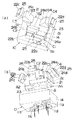
図1〜図3は光源ブロック10及び光学系ブロック20を拡大して図示した要部分解斜視図であり、これらの図を参照して光源ブロック10及び光学系ブロック20の構成を説明する。   FIGS. 1 to 3 are exploded perspective views of main parts showing the light source block 10 and the optical system block 20 in an enlarged manner. The configurations of the light source block 10 and the optical system block 20 will be described with reference to these drawings.

光源ブロック10は、レーザ光を出力する半導体レーザ素子のような発光素子12a及び発光素子12aから出力されたレーザ光をコリメート光に変換する投光レンズ12bとを円柱状のケース12cに収納してそれぞれ構成された複数のレーザ光源11a〜11dと、支持脚2に取着されたバッテリBから電源供給を受けて各レーザ光源11a〜11dの発光素子12aを駆動する駆動回路13とで構成される。   The light source block 10 houses a light emitting element 12a such as a semiconductor laser element that outputs laser light and a light projecting lens 12b that converts the laser light output from the light emitting element 12a into collimated light in a cylindrical case 12c. Each of the plurality of laser light sources 11a to 11d configured and a drive circuit 13 that receives power supply from the battery B attached to the support leg 2 and drives the light emitting elements 12a of the laser light sources 11a to 11d. .

ここで、レーザ光源11aは水平面と略平行な平面内で扇状に広がるライン光(水平ラインLh)を照射する光源、レーザ光源11bは鉛直面と略平行な平面内で扇状に広がるライン光(たちラインLv1)を照射する光源、レーザ光源11cはたちラインLv1と略平行な平面及び水平面に対してそれぞれ略垂直な平面内で、主に図3中左側の領域に扇状に広がるライン光(かねラインLv2)を照射する光源、レーザ光源11dはかねラインLv2が照射される平面内で主に図3中右側の領域に扇状に広がるライン光(かねラインLv3)を照射する光源であり、これら4つのレーザ光源11a〜11dは直方体状のボディ14(保持部材)を上下方向に貫通する取付孔14cに挿通させた状態で取り付けられている(図3参照)。   Here, the laser light source 11a is a light source that irradiates a line light (horizontal line Lh) that spreads in a fan shape in a plane substantially parallel to the horizontal plane, and the laser light source 11b is a line light that spreads in a fan shape in a plane substantially parallel to the vertical plane. The light source that irradiates the line Lv1), the laser light source 11c, is a line light that spreads in a fan shape mainly in the region on the left side in FIG. 3 in a plane substantially parallel to the horizontal line Lv1 and a plane substantially perpendicular to the horizontal plane. The laser light source 11d is a light source that irradiates fan-shaped line light (Kane line Lv3) mainly in the right side of FIG. 3 within the plane irradiated with the Kane line Lv2. The laser light sources 11a to 11d are attached in a state where the rectangular body 14 (holding member) is inserted through the attachment hole 14c penetrating in the vertical direction (see FIG. 3).

一方、光学系ブロック20は、4つのレーザ光源11a〜11dより上方に出力されたレーザ光がそれぞれ入射し、入射したレーザ光をそれぞれ所望の方向に反射することでレーザ光の光路を変化させるプリズムブロック21と、プリズムブロック21で光路が変えられたレーザ光を鉛直面或いは水平面と略平行な扇状のライン光に変換して出力する円筒レンズ22a〜22dとで構成される。   On the other hand, the optical system block 20 is a prism that changes the optical path of the laser light by allowing the laser light output above the four laser light sources 11a to 11d to enter and reflecting the incident laser light in a desired direction. The block 21 and cylindrical lenses 22a to 22d that convert the laser light whose optical path has been changed by the prism block 21 into fan-shaped line light that is substantially parallel to the vertical or horizontal plane and output it.

プリズムブロック21は透光性を有する合成樹脂により一体に形成されており、レーザ光源11a〜11dに対向する面(下面)が水平面と略平行な平坦面(この面を入射面Aと言う)に形成された平板部23と、平板部23の上面に各々のレーザ光源11a〜11dに対応して設けられた4つのプリズム部24a〜24dとを備えている。   The prism block 21 is integrally formed of a translucent synthetic resin, and a surface (lower surface) facing the laser light sources 11a to 11d is a flat surface substantially parallel to the horizontal surface (this surface is referred to as an incident surface A). The formed flat plate portion 23 and four prism portions 24a to 24d provided on the upper surface of the flat plate portion 23 corresponding to the respective laser light sources 11a to 11d are provided.

プリズム部24aは直角プリズムからなり、入射面Aにおけるレーザ光源11aとの対向エリアA1から入射したレーザ光はプリズム面B1によって反射され、レーザ光の光路が水平方向に変えられる。そして、プリズム面B1で反射されたレーザ光は、入射面Aに対して略垂直な出射面C1から外部に出射された後、出射面C1の前方に軸方向が鉛直方向に沿うように配置された円筒レンズ22aで、円筒レンズ22aの中心軸と略垂直な平面(水平面)内で扇状に広がるライン光に変換され、このライン光によって水平ラインLhが形成される。   The prism portion 24a is a right-angle prism, and the laser light incident from the area A1 facing the laser light source 11a on the incident surface A is reflected by the prism surface B1, and the optical path of the laser light is changed in the horizontal direction. Then, after the laser beam reflected by the prism surface B1 is emitted to the outside from the emission surface C1 substantially perpendicular to the incident surface A, it is arranged in front of the emission surface C1 so that the axial direction is along the vertical direction. The cylindrical lens 22a converts the light into fan-shaped line light in a plane (horizontal plane) substantially perpendicular to the central axis of the cylindrical lens 22a, and a horizontal line Lh is formed by the line light.

プリズム部24bは側面視の形状が四角形に形成された角柱形状であって、入射面Aにおけるレーザ光源11bとの対向エリアA2から入射したレーザ光は、入射面Aに対して斜めに傾斜するプリズム面B2で反射されて、レーザ光の光路が水平面よりも上向きに変えられる。そして、プリズム面B2で斜め上向きに反射されたレーザ光は、このレーザ光の光路に対して略垂直な出射面C2から外部に出射された後、出射面C2の前方に軸方向が水平方向に沿うように配置された円筒レンズ22bで、円筒レンズ22bの中心軸と略垂直な平面(鉛直面)内で扇状に広がるライン光に変換され、このライン光によりたちラインLv1が形成される。   The prism portion 24b has a prismatic shape with a quadrangular shape when viewed from the side, and the laser light incident from the area A2 facing the laser light source 11b on the incident surface A is inclined obliquely with respect to the incident surface A. Reflected by the surface B2, the optical path of the laser light is changed upward from the horizontal plane. Then, the laser beam reflected obliquely upward by the prism surface B2 is emitted to the outside from the emission surface C2 substantially perpendicular to the optical path of the laser beam, and then the axial direction is in the horizontal direction in front of the emission surface C2. The cylindrical lens 22b arranged along the axis is converted into line light spreading in a fan shape in a plane (vertical surface) substantially perpendicular to the central axis of the cylindrical lens 22b, and a straight line Lv1 is formed by the line light.

プリズム部24cは側面視の形状が四角形に形成された角柱形状(プリズム部24bと略同じ形状)であって、入射面Aにおけるレーザ光源11cとの対向エリアA3から入射したレーザ光は、入射面Aに対して斜めに傾斜するプリズム面B3で反射されて、レーザ光の光路が水平面よりも上向きに変えられる。そして、プリズム面B3で斜め上向きに反射されたレーザ光は、このレーザ光の光路に対して略垂直な出射面C3から外部に出射された後、出射面C3の前方に軸方向が水平方向に沿うように配置された円筒レンズ22cで、円筒レンズ22cの中心軸と略垂直な平面(鉛直面)内で扇状に広がるライン光に変換され、このライン光により主に図3中左側の領域に照射されるかねラインLv2が形成される。   The prism portion 24c has a prismatic shape (substantially the same shape as the prism portion 24b) formed in a quadrangular shape in a side view, and the laser light incident from the area A3 facing the laser light source 11c on the incident surface A is incident surface Reflected by the prism surface B3 inclined obliquely with respect to A, the optical path of the laser light is changed upward from the horizontal plane. Then, the laser beam reflected obliquely upward by the prism surface B3 is emitted to the outside from the emission surface C3 substantially perpendicular to the optical path of the laser beam, and then the axial direction is in the horizontal direction in front of the emission surface C3. The cylindrical lens 22c arranged along the axis is converted into line light that spreads in a fan shape within a plane (vertical surface) substantially perpendicular to the central axis of the cylindrical lens 22c, and this line light mainly causes the region on the left side in FIG. The shine line Lv2 is formed.

プリズム部24dは側面視の形状が四角形に形成された角柱形状(プリズム部24b,24cと略同じ形状)であって、入射面Aにおけるレーザ光源11dとの対向エリアA4から入射したレーザ光は、入射面Aに対して斜めに傾斜するプリズム面B4で反射されて、レーザ光の光路が水平面よりも上向きに変えられる。そして、プリズム面B4で斜め上向きに反射されたレーザ光は、このレーザ光の光路に対して略垂直な出射面C4から外部に出射された後、出射面C4の前方に軸方向が水平方向に沿うように配置された円筒レンズ22dで、円筒レンズ22dの中心軸と略垂直な平面(鉛直面)内で扇状に広がるライン光に変換され、このライン光により主に図3中右側の領域に照射されるかねラインLv3が形成される。   The prism portion 24d has a prismatic shape (substantially the same shape as the prism portions 24b and 24c) formed in a quadrangular shape when viewed from the side, and the laser light incident from the area A4 facing the laser light source 11d on the incident surface A is Reflected by the prism surface B4 inclined obliquely with respect to the incident surface A, the optical path of the laser light is changed upward from the horizontal plane. Then, the laser beam reflected obliquely upward by the prism surface B4 is emitted to the outside from the emission surface C4 substantially perpendicular to the optical path of the laser beam, and then the axial direction is in the horizontal direction in front of the emission surface C4. The cylindrical lens 22d arranged so as to be converted into line light that spreads in a fan shape within a plane (vertical surface) substantially perpendicular to the central axis of the cylindrical lens 22d, and this line light mainly causes the region on the right side in FIG. The shine line Lv3 is formed.

ここで、各プリズム部24a〜24dのプリズム面B1〜B4は、プリズム面B1〜B4に対するレーザ光の入射角が全反射角(臨界角)以上となるような角度で、レーザ光の光路に対して斜めに傾斜しているので、プリズム面B1〜B4に入射したレーザ光は略100%の反射効率で全反射されるようになっている。   Here, the prism surfaces B1 to B4 of the respective prism portions 24a to 24d are at an angle such that the incident angle of the laser beam with respect to the prism surfaces B1 to B4 is equal to or greater than the total reflection angle (critical angle), with respect to the optical path of the laser beam. Therefore, the laser light incident on the prism surfaces B1 to B4 is totally reflected with a reflection efficiency of approximately 100%.

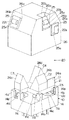
次に上述した光源ブロック10および光学系ブロック20のレーザ装置本体4への取付構造について図4〜図6を参照して説明する。   Next, a structure for attaching the light source block 10 and the optical system block 20 to the laser device body 4 will be described with reference to FIGS.

4個のレーザ光源11a〜11dが埋設した状態で取り付けられるボディ14の上面には、プリズムブロック21の平板部23の角部に対応する部位に、平板部23の角部外側面とそれぞれ当接する平面視略L字形の支持リブ14aが一体に突設されており、平板部23の角部と対向する支持リブ14aの2つの内側面でできる角部には平板部23の下面が載置される載置段部14bが支持リブ14aと一体に突設されている。尚、図1〜図3では図示を簡単にするため、支持リブ14a及び載置段部14bを省略して図示してある。   On the upper surface of the body 14 to which the four laser light sources 11a to 11d are embedded, the portions corresponding to the corners of the flat plate portion 23 of the prism block 21 are in contact with the outer side surfaces of the corner portions of the flat plate portion 23, respectively. A substantially rib-shaped support rib 14a in a plan view is integrally projected, and a lower surface of the flat plate portion 23 is placed on a corner portion formed by two inner surfaces of the support rib 14a facing the corner portion of the flat plate portion 23. The mounting step portion 14b protrudes integrally with the support rib 14a. In FIG. 1 to FIG. 3, the support rib 14 a and the mounting step 14 b are omitted for the sake of simplicity.

一方、4個の円筒レンズ22a〜22dは、それぞれ、矩形板状の取付板25に貫設された嵌合孔25aに圧入や接着などの方法で取り付けられている。そして、円筒レンズ22a…がそれぞれ取着された4つの取付板25は、下面が開口した略箱状のカバー26に貫設した角孔状の窓孔26aに圧入や接着などの方法で固着されている。なお、カバー26の開口部の大きさはボディ14よりも若干大きな寸法に形成されている。また、垂直ラインを出力するための円筒レンズ22b〜22dを固着した取付板25が取着されるカバー26の部位には、対応するプリズム部24b〜24dの出射面C2〜C4と略平行なテーパ面26bが形成されている。   On the other hand, each of the four cylindrical lenses 22a to 22d is attached to a fitting hole 25a penetrating through the rectangular plate-like attachment plate 25 by a method such as press fitting or adhesion. The four mounting plates 25 to which the cylindrical lenses 22a are respectively attached are fixed to a square hole-shaped window hole 26a penetrating the substantially box-shaped cover 26 whose bottom surface is opened by a method such as press fitting or adhesion. ing. Note that the size of the opening of the cover 26 is slightly larger than that of the body 14. Further, the portion of the cover 26 to which the mounting plate 25 to which the cylindrical lenses 22b to 22d for outputting the vertical lines are fixed is attached is a taper substantially parallel to the emission surfaces C2 to C4 of the corresponding prism portions 24b to 24d. A surface 26b is formed.

而して、この光源ブロック10及び光学系ブロック20を組み立てるに当たっては、先ず円筒レンズ22a〜22dが固着された取付板25を、円筒レンズ22a〜22dの軸方向が所定の方向を向くようにしてカバー26の窓孔26aに固定する(図4参照)。次にプリズムブロック21をボディ14の載置段部14b上に載置して固定すると、プリズムブロック21の角部が支持リブ14aの2つの内側面と当接することで、プリズムブロック21がボディ14に対して位置決めされ、各レーザ光源11a〜11dがプリズムブロック21下面の対向エリアA1〜A4にそれぞれ対向する(図5参照)。そして、カバー26をボディ14の上側から被せて固定すると、カバー26とボディ14とで囲まれる空間内にプリズムブロック21が収納され、光源ブロック10及び光学系ブロック20の組立が完了する。この時、カバー26の内側面がボディ14の側面と当接することで、カバー26の平面方向における位置ずれが規制されるとともに、ボディ14の上面に突設された支持リブ14aがカバー26の内側面に突設された係止段部(図示せず)と当接することで、カバー26の上下方向における位置ずれが規制されており、各プリズム部24a〜24dの出射面C1〜C4の前方に円筒レンズ22a〜22dが配置されるようになっている。そして、両ブロック10,20を組み立てた状態でボディ14をレーザ装置本体4に取り付けることにより、光源ブロック10と光学系ブロック20とがレーザ装置本体4に固定されるのである。   Thus, in assembling the light source block 10 and the optical system block 20, first, the mounting plate 25 to which the cylindrical lenses 22a to 22d are fixed is placed so that the axial direction of the cylindrical lenses 22a to 22d is directed to a predetermined direction. It fixes to the window hole 26a of the cover 26 (refer FIG. 4). Next, when the prism block 21 is mounted and fixed on the mounting step portion 14b of the body 14, the corners of the prism block 21 come into contact with the two inner side surfaces of the support rib 14a, so that the prism block 21 is moved to the body 14. The laser light sources 11a to 11d face the facing areas A1 to A4 on the lower surface of the prism block 21, respectively (see FIG. 5). When the cover 26 is placed and fixed from the upper side of the body 14, the prism block 21 is housed in a space surrounded by the cover 26 and the body 14, and the assembly of the light source block 10 and the optical system block 20 is completed. At this time, the inner side surface of the cover 26 abuts on the side surface of the body 14, so that the positional deviation in the planar direction of the cover 26 is restricted, and the support ribs 14 a protruding from the upper surface of the body 14 are provided inside the cover 26. By abutting a locking step (not shown) projecting on the side surface, the vertical displacement of the cover 26 is restricted, and in front of the exit surfaces C1 to C4 of the prism portions 24a to 24d. Cylindrical lenses 22a to 22d are arranged. Then, the light source block 10 and the optical system block 20 are fixed to the laser device body 4 by attaching the body 14 to the laser device body 4 in a state where both the blocks 10 and 20 are assembled.

本実施形態のレーザ墨出し器は上記のような構造を有しており、垂直ラインを出力するレーザ光源11b〜11dを含め全てのレーザ光源11a〜11dが、円柱状のレーザ装置本体4の上側部(ジンバル機構3の枢支軸よりも上側)に、レーザ装置本体4の軸方向と略平行するように取り付けられているので、レーザ光源11b〜11dを水平面に対して斜め上向きにレーザ装置本体4に取り付けた場合に比べてレーザ装置本体4の上側部分の径を小さくでき、それによってレーザ装置本体4の重心位置を下げることができる。ここで、レーザ装置本体4はジンバル機構3により全周方向において揺動自在に枢支されているので、レーザ装置本体4の重心位置を下げることで、レーザ装置本体4の停止位置(静止位置)が安定して位置決め精度が向上し、レーザ出力部から出力される垂直ライン或いは水平ラインの垂直度や水平度が高くなって、墨出しの精度が向上する。さらに複数のレーザ光源11a〜11dはレーザ装置本体4に対して互いに近接して取り付けられているので、各レーザ光源11a〜11dに給電線を引き回す距離が短くて済み、レーザ装置本体4が揺動したとしても、給電線の位置ずれが起こりにくくなるから、給電線の位置ずれによってレーザ装置本体4の停止位置がずれるのを防止して、レーザ装置本体4の位置決め精度を向上させることができ、レーザ出力部から出力される垂直ライン或いは水平ラインの垂直度や水平度が高くなって、墨出しの精度が向上する。   The laser marking device of the present embodiment has the above-described structure, and all of the laser light sources 11a to 11d including the laser light sources 11b to 11d that output vertical lines are located above the cylindrical laser device body 4. Since it is attached to the portion (above the pivot shaft of the gimbal mechanism 3) so as to be substantially parallel to the axial direction of the laser device main body 4, the laser light sources 11b to 11d are obliquely upward with respect to the horizontal plane. The diameter of the upper portion of the laser device main body 4 can be made smaller than the case where the laser device main body 4 is attached to the laser device main body 4, thereby lowering the center of gravity of the laser device main body 4. Here, since the laser device main body 4 is pivotally supported by the gimbal mechanism 3 so as to be swingable in the entire circumferential direction, the laser device main body 4 can be stopped (rest position) by lowering the position of the center of gravity of the laser device main body 4. However, the positioning accuracy is improved and the verticality or horizontality of the vertical line or horizontal line output from the laser output unit is increased, so that the accuracy of marking is improved. Further, since the plurality of laser light sources 11a to 11d are attached close to each other with respect to the laser device main body 4, the distance for feeding the power supply line to each laser light source 11a to 11d can be short, and the laser device main body 4 swings. Even if it does, since it becomes difficult to occur the position shift of the feed line, it is possible to prevent the stop position of the laser apparatus body 4 from shifting due to the position shift of the feed line, and to improve the positioning accuracy of the laser apparatus body 4, The vertical or horizontal level of the vertical line or horizontal line output from the laser output unit is increased, and the accuracy of inking is improved.

また本実施形態では、レーザ光源11a〜11dより上方に出力されたレーザ光の光路を所望の方向に変化させる光学部材としてプリズム部24a〜24dを用い、各プリズム部24a〜24dのプリズム面B1〜B4でレーザ光を所望の方向に全反射しているので、レーザ光を略100%の反射効率で反射することができ、レーザ光を効率良く利用することができる。   In the present embodiment, prism portions 24a to 24d are used as optical members that change the optical path of the laser light output above the laser light sources 11a to 11d in a desired direction, and the prism surfaces B1 to B1 of the prism portions 24a to 24d are used. Since the laser beam is totally reflected in a desired direction at B4, the laser beam can be reflected with a reflection efficiency of approximately 100%, and the laser beam can be used efficiently.

また更に、本実施形態ではレーザ光源11a…と、各レーザ光源11a…からのレーザ光の光路を変化させるプリズム部24a…と、各プリズム部24a…で光路が変換されたレーザ光からライン光を生成する円筒レンズ22a…とを4組ずつ備え、各々の組でレーザ出力部を構成しており、各レーザ出力部のプリズム部24a〜24dが平板部23の上面に一体に形成されたプリズムブロック21を用いている。ここで、複数のプリズム部24a〜24dを別々に形成した場合はプリズム部24a〜24dを組み込む際のガタによって、レーザ出力部から出力されるレーザ光の向きにズレが生じるが、複数のプリズム部24a〜24dをプリズムブロック21に一体に形成してあるので、レーザ光の方向が組込時のガタ等の影響を受けることはなく、各プリズム部24a〜24dのプリズム面B1〜B4の相対角度によって決まるから、レーザ光の照射方向の精度をさらに向上させることができる。また複数のプリズム部24a〜24dがプリズムブロック21と一体に形成されているので、部品点数を削減して、組立の作業性を向上させることもできる。またプリズムブロック21はアクリルやポリカーボネートなどの合成樹脂製であって、樹脂成形により形成することができるので、光学部材として例えば反射鏡を用いる場合に比べ、光学部材の製造コストを低減できるという利点がある。尚、プリズムブロック21をガラスで形成しても良いことは言うまでもない。また、本実施形態では全てのレーザ出力部のプリズム部24a〜24dをプリズムブロック21と一体に形成しているが、4つのプリズム部24a〜24dの内、少なくとも2つを一体に形成すれば良く、上述と同様にレーザ光の向きのズレを抑制したり、組立作業性が向上するという利点がある。   Furthermore, in the present embodiment, line light is generated from the laser light sources 11a, prism sections 24a that change the optical paths of the laser beams from the laser light sources 11a, and laser beams whose optical paths are converted by the prism sections 24a. 4 sets of cylindrical lenses 22a to be generated, and each set constitutes a laser output section, and prism sections 24a to 24d of each laser output section are integrally formed on the upper surface of the flat plate section 23. 21 is used. Here, when the plurality of prism portions 24a to 24d are separately formed, a deviation occurs in the direction of the laser beam output from the laser output portion due to backlash when the prism portions 24a to 24d are incorporated. Since 24a to 24d are formed integrally with the prism block 21, the direction of the laser beam is not affected by play or the like when assembled, and the relative angles of the prism surfaces B1 to B4 of the respective prism portions 24a to 24d. Therefore, the accuracy of the laser beam irradiation direction can be further improved. Further, since the plurality of prism portions 24a to 24d are formed integrally with the prism block 21, the number of parts can be reduced and the assembly workability can be improved. The prism block 21 is made of a synthetic resin such as acrylic or polycarbonate, and can be formed by resin molding. Therefore, there is an advantage that the manufacturing cost of the optical member can be reduced as compared with the case where a reflecting mirror is used as the optical member. is there. Needless to say, the prism block 21 may be made of glass. In the present embodiment, the prism portions 24a to 24d of all the laser output portions are formed integrally with the prism block 21, but at least two of the four prism portions 24a to 24d may be formed integrally. As described above, there are advantages that the deviation of the direction of the laser beam is suppressed and the assembling workability is improved.

さらに、本実施形態では4種類のライン光(水平ラインLh、たちラインLv1、及びかねラインLv2,Lv3)を照射するために用いる4組のレーザ光源11a…及び円筒レンズ22a…とプリズムブロック21とを用いており、ボディ14には4つのレーザ光源11a…が着脱自在に取り付けられる取付手段としての取付孔14cが設けられ、カバー26には円筒レンズ22a…をそれぞれ保持した4つの取付板25が着脱自在に取り付けられる取付手段としての窓孔26aが設けられており、またボディ14にはプリズムブロック21を取り付けるための支持リブ14aが設けられている。したがって、上記4種類のライン光の内、所望のライン光を照射するために必要なプリズム部24a…のみをプリズムブロック21に形成するとともに、プリズムブロック21に設けられたプリズム部24a…に対応するレーザ光源11a…および円筒レンズ22a…のみを取付部材たるボディ14又はカバー26に選択的に取り付けることで、ライン光の出力仕様に合わせて、不要なレーザ光源11a…や円筒レンズ22a…やプリズム部24a…を無くして、レーザ光源11a…や円筒レンズ22a…やプリズム部24a…の組み合わせを変えることができる。したがって、出力するライン光の数が少ない場合には、レーザ装置本体4に取り付けられるレーザ光源11a…や円筒レンズ22a…や光学部材の数を減らして、レーザ装置本体4の軽量化を図ることができ、さらにレーザ装置本体4の軽量化によって落下等の衝撃が加わった場合にレーザ装置本体4を支持するジンバル機構3に加わる負荷が低減され、ジンバル機構3の破損を防止することができる。   Furthermore, in this embodiment, four sets of laser light sources 11a, cylindrical lenses 22a, and prism block 21 used for irradiating four types of line light (horizontal line Lh, vertical line Lv1, and chain line Lv2, Lv3) The body 14 is provided with mounting holes 14c as mounting means for detachably mounting the four laser light sources 11a, and the cover 26 has four mounting plates 25 each holding a cylindrical lens 22a. A window hole 26a is provided as attachment means that can be detachably attached, and a support rib 14a for attaching the prism block 21 is provided in the body 14. Therefore, among the four types of line light, only the prism portions 24a necessary for irradiating the desired line light are formed in the prism block 21 and correspond to the prism portions 24a provided in the prism block 21. By selectively attaching only the laser light source 11a ... and the cylindrical lens 22a ... to the body 14 or the cover 26 as an attachment member, an unnecessary laser light source 11a ..., a cylindrical lens 22a ... 24a can be eliminated and the combination of the laser light sources 11a, the cylindrical lenses 22a, and the prism portions 24a can be changed. Therefore, when the number of line lights to be output is small, it is possible to reduce the number of laser light sources 11a... And cylindrical lenses 22a. In addition, the load applied to the gimbal mechanism 3 that supports the laser device body 4 when an impact such as dropping is applied due to the weight reduction of the laser device body 4 can be reduced, and the gimbal mechanism 3 can be prevented from being damaged.

(実施形態2)
本発明の実施形態2を図8〜図13に基づいて説明する。上述の実施形態1では4つのレーザ光源11a〜11dを上下方向と略平行にしてボディ14に取り付けているのに対して、本実施形態では垂直ライン(たちラインLv1及びかねラインLv2,Lv3)を出力するための3つのレーザ光源11b〜11dを上下方向と略平行にしてボディ14に取り付けるとともに、水平ラインLhを出力するためのレーザ光源11aを水平方向と略平行にしてレーザ装置本体4に取り付けてある。尚、レーザ墨出し器の基本構成は実施形態1と同様であるので、共通する構成要素には同一の符号を付して、その説明は省略する。
(Embodiment 2)
A second embodiment of the present invention will be described with reference to FIGS. In the first embodiment described above, the four laser light sources 11a to 11d are attached to the body 14 so as to be substantially parallel to the vertical direction, whereas in the present embodiment, vertical lines (line Lv1 and chain lines Lv2, Lv3) are provided. The three laser light sources 11b to 11d for output are attached to the body 14 so as to be substantially parallel to the vertical direction, and the laser light source 11a for outputting the horizontal line Lh is attached to the laser device body 4 so as to be substantially parallel to the horizontal direction. It is. Since the basic configuration of the laser marking device is the same as that of the first embodiment, common components are denoted by the same reference numerals, and description thereof is omitted.

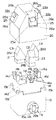
図8及び図9(a)(b)は光源ブロック10及び光学系ブロック20を拡大して図示した要部分解斜視図であり、これらの図を参照して光源ブロック10及び光学系ブロック20の構成を説明する。   8 and 9 (a) and 9 (b) are exploded perspective views of the main part showing the light source block 10 and the optical system block 20 in an enlarged manner. With reference to these drawings, the light source block 10 and the optical system block 20 are shown. The configuration will be described.

光源ブロック10は、水平面に略平行な平面内で扇状に広がる水平ラインLhを照射するレーザ光源11aと、鉛直面と略平行な平面内で扇状に広がるたちラインLv1を照射するレーザ光源11bと、たちラインLv1に略平行な平面及び水平面に対してそれぞれ略垂直な平面内で扇状に広がるかねラインLv2を照射するレーザ光源11cと、かねラインLv2が照射される平面内で扇状に広がるかねラインLv3を照射するレーザ光源11dとを備える。そして、4つのレーザ光源11a〜11dの内、垂直ラインを出力するための3つのレーザ光源11b〜11dは、直方体状のボディ14を上下方向に貫通する取付孔14cに挿通させた状態で取り付けられている。また、水平ラインを出力するためのレーザ光源11aは、ボディ14とは別体に形成された直方体状のベース15に、このベース15を水平方向に貫通する取付孔15aに挿通させた状態で取り付けられている。   The light source block 10 includes a laser light source 11a that irradiates a horizontal line Lh that extends in a fan shape in a plane substantially parallel to the horizontal plane, a laser light source 11b that irradiates a line Lv1 that extends in a fan shape in a plane substantially parallel to the vertical plane, A laser light source 11c that irradiates a fan-shaped line Lv2 that extends in a fan shape in a plane substantially parallel to the line Lv1 and a plane that is substantially perpendicular to the horizontal plane, and a fan-shaped line Lv3 that extends in a fan shape in a plane that is irradiated with the money line Lv2. And a laser light source 11d for irradiating. Of the four laser light sources 11a to 11d, three laser light sources 11b to 11d for outputting a vertical line are attached in a state of being inserted through attachment holes 14c penetrating the rectangular parallelepiped body 14 in the vertical direction. ing. The laser light source 11a for outputting a horizontal line is attached to a rectangular parallelepiped base 15 formed separately from the body 14 in a state where the base 15 is inserted into an attachment hole 15a penetrating in the horizontal direction. It has been.

ここで、レーザ光源11aは円柱状のケース12cを有し、このケース12cの内部に発光素子12aと投光レンズ12bとを収納するとともに、ケース12cの前面に円筒レンズ22aを半分埋設させた状態で取り付けてある。円筒レンズ22aはその軸方向が上下方向と略平行するようにして配置されており、発光素子12aから投光レンズ12bを介して入射したレーザ光は円筒レンズ22aによって、円筒レンズ22aの軸方向と垂直な平面(水平面)内で扇状に広がるライン光に変換され、このライン光によって水平ラインLhが形成される。   Here, the laser light source 11a has a cylindrical case 12c, the light emitting element 12a and the light projecting lens 12b are housed in the case 12c, and the cylindrical lens 22a is half embedded in the front surface of the case 12c. It is attached with. The cylindrical lens 22a is arranged so that its axial direction is substantially parallel to the vertical direction, and the laser light incident from the light emitting element 12a via the light projecting lens 12b is aligned with the axial direction of the cylindrical lens 22a by the cylindrical lens 22a. It is converted into line light that spreads in a fan shape within a vertical plane (horizontal plane), and a horizontal line Lh is formed by this line light.

一方、垂直ラインを出力する3つのレーザ光源11b〜11dより出力されたレーザ光は、それぞれ、プリズムブロック21に設けられたプリズム部24b〜24dによってその光路が所望の方向に変えられる。   On the other hand, the optical paths of the laser beams output from the three laser light sources 11b to 11d that output the vertical lines are changed in desired directions by the prism portions 24b to 24d provided in the prism block 21, respectively.

プリズムブロック21は透光性を有する合成樹脂により成形され、レーザ光源11b〜11dと対向する面(下面)が水平面と略平行な平坦面(入射面A)に形成された平面視略T字形の平板部23と、平板部23の上面に各々のレーザ光源11b〜11dに対応してそれぞれ設けられた3つのプリズム部24b〜24dとを備えている。   The prism block 21 is formed of a translucent synthetic resin, and has a substantially T-shaped plan view in which a surface (lower surface) facing the laser light sources 11b to 11d is formed on a flat surface (incident surface A) substantially parallel to the horizontal surface. A flat plate portion 23 and three prism portions 24b to 24d respectively provided on the upper surface of the flat plate portion 23 corresponding to the respective laser light sources 11b to 11d are provided.

プリズム部24bは側面視の形状が四角形に形成された角柱形状であって、入射面Aにおけるレーザ光源11bとの対向エリアA2から入射したレーザ光が、入射面Aに対して斜めに傾斜するプリズム面B2で反射されて、レーザ光の光路が水平面よりも上向きに変えられる。そして、プリズム面B2で斜め上向きに反射されたレーザ光は、このレーザ光の光路に対して略垂直な出射面C2から外部に出射された後、出射面C2の前方に軸方向が水平方向に沿うように配置された円筒レンズ22bに入射する。円筒レンズ22bに入射したレーザ光は、この円筒レンズ22bの中心軸と略垂直な平面(鉛直面)内で扇状に広がるライン光に変換され、このライン光によりたちラインLv1が形成される。   The prism portion 24b is a prism having a quadrangular shape when viewed from the side, and the laser beam incident from the area A2 facing the laser light source 11b on the incident surface A is obliquely inclined with respect to the incident surface A. Reflected by the surface B2, the optical path of the laser light is changed upward from the horizontal plane. Then, the laser beam reflected obliquely upward by the prism surface B2 is emitted to the outside from the emission surface C2 substantially perpendicular to the optical path of the laser beam, and then the axial direction is in the horizontal direction in front of the emission surface C2. The light enters the cylindrical lens 22b that is disposed along. The laser light incident on the cylindrical lens 22b is converted into line light that spreads in a fan shape in a plane (vertical surface) substantially perpendicular to the central axis of the cylindrical lens 22b, and a line Lv1 is formed by the line light.

プリズム部24cは側面視の形状が四角形に形成された角柱形状であって、入射面Aにおけるレーザ光源11cとの対向エリアA3から入射したレーザ光が、入射面Aに対して斜めに傾斜するプリズム面B3で反射されて、レーザ光の光路が水平面よりも上向きに変えられる。そして、プリズム面B3で斜め上向きに反射されたレーザ光は、このレーザ光の光路に対して略垂直な出射面C3から外部に出射された後、出射面C3の前方に軸方向が円筒レンズ22bの軸方向と略直交し、且つ、水平方向と略平行になるように配置された円筒レンズ22cに入射する。円筒レンズ22cに入射したレーザ光は、この円筒レンズ22cの中心軸と略垂直な平面(たちラインLv1と平行な平面及び水平面に対してそれぞれ略垂直な平面)内で扇状に広がるライン光に変換され、このライン光により主に図8中左側の領域に照射されるかねラインLv2が形成される。   The prism portion 24c has a prismatic shape with a quadrangular shape when viewed from the side, and the laser beam incident from the area A3 facing the laser light source 11c on the incident surface A is inclined obliquely with respect to the incident surface A. Reflected by the surface B3, the optical path of the laser light is changed upward from the horizontal plane. The laser beam reflected obliquely upward by the prism surface B3 is emitted to the outside from the emission surface C3 substantially perpendicular to the optical path of the laser beam, and then the axial direction of the cylindrical lens 22b is in front of the emission surface C3. Is incident on a cylindrical lens 22c that is arranged so as to be substantially orthogonal to the axial direction of the lens and to be substantially parallel to the horizontal direction. The laser light incident on the cylindrical lens 22c is converted into line light that spreads in a fan shape in a plane substantially perpendicular to the central axis of the cylindrical lens 22c (a plane parallel to the line Lv1 and a plane substantially perpendicular to the horizontal plane). As a result, the line Lv2 that is mainly irradiated to the left region in FIG. 8 is formed.

またプリズム部24dは側面視の形状が四角形に形成された角柱形状であって、入射面Aにおけるレーザ光源11dとの対向エリアA4から入射したレーザ光が、入射面Aに対して斜めに傾斜するプリズム面B4で反射されて、レーザ光の光路が水平面よりも上向きに変えられる。そして、プリズム面B4で斜め上向きに反射されたレーザ光は、このレーザ光の光路に対して略垂直な出射面C4から外部に出射された後、出射面C4の前方に軸方向が円筒レンズ22cの軸方向と略平行になるように配置された円筒レンズ22dに入射する。円筒レンズ22dに入射したレーザ光は、この円筒レンズ22dの中心軸と略垂直な平面(かねラインLv2が照射される鉛直面)内で扇状に広がるライン光に変換され、このライン光により主に図8中右側の領域に照射されるかねラインLv3が形成される。   The prism portion 24d has a prismatic shape in which the shape in side view is a quadrangle, and the laser light incident from the area A4 facing the laser light source 11d on the incident surface A is inclined with respect to the incident surface A. Reflected by the prism surface B4, the optical path of the laser light is changed upward from the horizontal plane. The laser beam reflected obliquely upward by the prism surface B4 is emitted to the outside from the emission surface C4 substantially perpendicular to the optical path of the laser beam, and then the cylindrical lens 22c has an axial direction in front of the emission surface C4. Is incident on a cylindrical lens 22d that is arranged so as to be substantially parallel to the axial direction. The laser light incident on the cylindrical lens 22d is converted into line light that spreads in a fan shape in a plane (vertical surface irradiated with the curve line Lv2) that is substantially perpendicular to the central axis of the cylindrical lens 22d. A money line Lv3 is formed to irradiate the right region in FIG.

ここで、各プリズム部24b〜24dのプリズム面B2〜B4は、プリズム面B2〜B4に対するレーザ光の入射角が全反射角(臨界角)以上となるような角度で傾斜しているので、プリズム面B2〜B4に入射したレーザ光は略100%の反射効率で全反射されるようになっている。   Here, the prism surfaces B2 to B4 of the respective prism portions 24b to 24d are inclined at an angle such that the incident angle of the laser beam with respect to the prism surfaces B2 to B4 is equal to or greater than the total reflection angle (critical angle). The laser light incident on the surfaces B2 to B4 is totally reflected with a reflection efficiency of approximately 100%.

次に上述した光源ブロック10および光学系ブロック20のレーザ装置本体4への取付構造について図10〜図13を参照して説明する。   Next, a structure for attaching the light source block 10 and the optical system block 20 to the laser device main body 4 will be described with reference to FIGS.

レーザ光源11aが取り付けられるベース15は略直方体状であって、ベース15上面の縦横の寸法はボディ14底面の縦横の寸法よりも一回り大きい寸法に形成されており、ベース15上面の四隅にはボディ14の角部の外側面とそれぞれ当接する平面視略L字形のリブ15bが一体に突設されている。またベース15上面の略中央にはボディ14の下面から突出する各レーザ光源11b〜11dの端子ピンを逃がすための凹所15cが形成されている。   The base 15 to which the laser light source 11a is attached has a substantially rectangular parallelepiped shape. The vertical and horizontal dimensions of the upper surface of the base 15 are formed to be slightly larger than the vertical and horizontal dimensions of the bottom surface of the body 14, and the four corners of the upper surface of the base 15 are formed. A rib 15b having a substantially L-shape in plan view that abuts against the outer surface of the corner portion of the body 14 is integrally provided. In addition, a recess 15c for allowing the terminal pins of the laser light sources 11b to 11d projecting from the lower surface of the body 14 to escape is formed in the approximate center of the upper surface of the base 15.

一方、3個のレーザ光源11b〜11dが埋設した状態で取り付けられるボディ14の上面には、プリズムブロック21の平板部23の横棒部分の角部に対応する部位に、各角部の外側面とそれぞれ当接する平面視略L字形の支持リブ14aが一体に形成され、縦棒部分の角部と対向する支持リブ14aの2つの内側面でできる角部には平板部23の下面が載置される載置段部14bが支持リブ14aと一体に突設されている。またボディ14の上面には、平板部23の縦棒部分の両側縁に対応する部位に、縦棒部分の側縁とそれぞれ当接する短冊状の支持リブ14d,14dが一体に形成されており、各支持リブ14dの先端部には平板部23の下面が載置される載置段部14eが設けられている。   On the other hand, on the upper surface of the body 14 to which the three laser light sources 11b to 11d are embedded, the outer surface of each corner is located at a portion corresponding to the corner of the horizontal bar portion of the flat plate portion 23 of the prism block 21. Are formed integrally with each other, and the lower surface of the flat plate portion 23 is placed on the corner portion formed by the two inner surfaces of the support rib 14a facing the corner portion of the vertical bar portion. The mounting step portion 14b is projected integrally with the support rib 14a. On the upper surface of the body 14, strip-shaped support ribs 14d and 14d that are in contact with the side edges of the vertical bar portion are integrally formed at portions corresponding to both side edges of the vertical bar portion of the flat plate portion 23, respectively. A mounting step portion 14e on which the lower surface of the flat plate portion 23 is mounted is provided at the tip of each support rib 14d.

また、3個の円筒レンズ22b〜22dは、それぞれ、矩形板状の取付板25に貫設された嵌合孔25aに圧入や接着などの方法で取り付けられている。そして、円筒レンズ22b〜22dが取着された3つの取付板25は、下面が開口した略箱状のカバー26に貫設した角孔状の窓孔26aに圧入や接着などの方法で固着されている。なお、カバー26の開口部の大きさはボディ14よりも若干大きな寸法に形成されている。また、取付板25が取着されるカバー26の部位には、対応するプリズム部24b〜24dの出射面C2〜C4と略平行なテーパ面26bが形成されている。   Each of the three cylindrical lenses 22b to 22d is attached to a fitting hole 25a penetrating the rectangular plate-like attachment plate 25 by a method such as press fitting or adhesion. Then, the three mounting plates 25 to which the cylindrical lenses 22b to 22d are attached are fixed to a square hole-like window hole 26a penetrating the substantially box-shaped cover 26 whose lower surface is opened by a method such as press fitting or adhesion. ing. Note that the size of the opening of the cover 26 is slightly larger than that of the body 14. Further, a tapered surface 26b substantially parallel to the emission surfaces C2 to C4 of the corresponding prism portions 24b to 24d is formed at the portion of the cover 26 to which the mounting plate 25 is attached.

而して、この光源ブロック10及び光学系ブロック20を組み立てるに当たっては、先ずレーザ光源11aをベース15に貫設された取付孔15aに挿通して、ベース15に保持させるとともに、レーザ光源11b〜11dをボディ14に貫設された取付孔14cに挿通して、ボディ14に保持させ、さらに円筒レンズ22b〜22dがそれぞれ固着された取付板25を、円筒レンズ22b〜22dの軸方向が所定の方向を向くようにしてカバー26の窓孔26aに固定する(図10及び図11参照)。そして、レーザ光源11b〜11dが取着されたボディ14を、レーザ光源11aが取着されたベース15の上面に載置して固定すると、支持リブ15bがボディ14の角部と当接することで、ボディ14がベースに対して位置決めされる。次にプリズムブロック21をボディ14の載置段部14b,14e上に載置して固定すると、平板部23の横棒部分の角部が支持リブ14aの2つの内側面に当接するとともに、縦棒部分の両側縁が支持リブ14dの側縁と当接することで、プリズムブロック21がボディ14に対して位置決めされ、各レーザ光源11b〜11dがプリズムブロック21下面の対向エリアA2〜A4にそれぞれ対向する(図12参照)。そして、カバー26をボディ14の上側から被せて固定すると、カバー26とボディ14とで囲まれる空間内にプリズムブロック21が収納され、光源ブロック10及び光学系ブロック20の組立が完了する。この時、カバー26の内側面がボディ14の側面と当接することで、カバー26の平面方向における位置ずれが規制されるとともに、ボディ14の上面に突設された支持リブ14aがカバー26の内側面に突設された係止段部(図示せず)と当接することで、カバー26の上下方向における位置ずれが規制されており、各プリズム部24b〜24dの出射面C2〜C4の前方に円筒レンズ22b〜22dが配置されるようになっている。そして、両ブロック10,20を組み立てた状態でベース15をレーザ装置本体4に固定することにより、光源ブロック10と光学系ブロック20とがレーザ装置本体4に固定されるのである。   Thus, in assembling the light source block 10 and the optical system block 20, first, the laser light source 11a is inserted into the mounting hole 15a penetrating the base 15 and held in the base 15, and the laser light sources 11b to 11d. Is inserted into a mounting hole 14c penetrating the body 14 and is held by the body 14, and the mounting plate 25 to which the cylindrical lenses 22b to 22d are fixed is attached to the cylindrical lens 22b to 22d in a predetermined direction. It fixes to the window hole 26a of the cover 26 so that it may face (refer FIG.10 and FIG.11). Then, when the body 14 to which the laser light sources 11b to 11d are attached is placed and fixed on the upper surface of the base 15 to which the laser light source 11a is attached, the support ribs 15b come into contact with the corners of the body 14. The body 14 is positioned with respect to the base. Next, when the prism block 21 is mounted and fixed on the mounting steps 14b and 14e of the body 14, the corners of the horizontal bar portion of the flat plate portion 23 abut against the two inner surfaces of the support rib 14a, and the The prism block 21 is positioned with respect to the body 14 by the both side edges of the rod portion being in contact with the side edges of the support rib 14d, and the laser light sources 11b to 11d respectively face the facing areas A2 to A4 on the lower surface of the prism block 21. (See FIG. 12). When the cover 26 is placed and fixed from the upper side of the body 14, the prism block 21 is housed in a space surrounded by the cover 26 and the body 14, and the assembly of the light source block 10 and the optical system block 20 is completed. At this time, the inner side surface of the cover 26 abuts on the side surface of the body 14, so that the positional deviation in the planar direction of the cover 26 is restricted, and the support ribs 14 a protruding from the upper surface of the body 14 are provided inside the cover 26. By abutting a locking step portion (not shown) projecting on the side surface, the vertical displacement of the cover 26 is restricted, and in front of the emission surfaces C2 to C4 of the prism portions 24b to 24d. Cylindrical lenses 22b to 22d are arranged. The light source block 10 and the optical system block 20 are fixed to the laser device main body 4 by fixing the base 15 to the laser device main body 4 in a state where both the blocks 10 and 20 are assembled.

本実施形態のレーザ墨出し器は上記のような構造を有しており、垂直ライン(たちラインLv1及びかねラインLv2,Lv3)を出力するレーザ光源11b〜11dは、円柱状のレーザ装置本体4の上側部(ジンバル機構3の枢支軸よりも上側)に、レーザ装置本体4の軸方向と略平行するように取り付けられているので、レーザ光源11b…自体を水平面に対して斜め上向きにしてレーザ装置本体4に取り付ける場合に比べてレーザ装置本体4の上側部分の径を小さくすることができ、それによってレーザ装置本体4の重心位置を下げることができる。ここで、レーザ装置本体4はジンバル機構3により全周方向において揺動自在に枢支されているので、レーザ装置本体4の重心位置を下げることで、レーザ装置本体4の停止位置(静止位置)が安定して位置決め精度が向上し、レーザ出力部から出力される垂直ラインの垂直度が高くなって、墨出しの精度が向上する。さらに複数のレーザ光源11b〜11dはレーザ装置本体4に対して互いに近接して取り付けられているので、各レーザ光源11b〜11dに給電線を引き回す距離が短くて済み、レーザ装置本体4が揺動したとしても、給電線の位置ずれが起こりにくくなるから、給電線の位置ずれによってレーザ装置本体4の停止位置がずれるのを防止して、レーザ装置本体4の位置決め精度を向上させることができ、レーザ出力部から出力される垂直ラインの垂直度が高くなって、墨出しの精度が向上する。   The laser marking device of the present embodiment has the above-described structure, and the laser light sources 11b to 11d that output vertical lines (the vertical line Lv1 and the fringe lines Lv2 and Lv3) are columnar laser device bodies 4 respectively. Are mounted so as to be substantially parallel to the axial direction of the laser device main body 4 so that the laser light source 11b itself is inclined upward with respect to the horizontal plane. The diameter of the upper portion of the laser device main body 4 can be reduced compared with the case where it is attached to the laser device main body 4, thereby lowering the position of the center of gravity of the laser device main body 4. Here, since the laser device main body 4 is pivotally supported by the gimbal mechanism 3 so as to be swingable in the entire circumferential direction, the laser device main body 4 can be stopped (rest position) by lowering the position of the center of gravity of the laser device main body 4. However, the positioning accuracy is improved and the verticality of the vertical line output from the laser output unit is increased, so that the accuracy of marking is improved. Further, since the plurality of laser light sources 11b to 11d are mounted close to each other with respect to the laser device main body 4, the distance for feeding the power supply line to each laser light source 11b to 11d can be short, and the laser device main body 4 swings. Even if it does, since it becomes difficult to occur the position shift of the feed line, it is possible to prevent the stop position of the laser apparatus body 4 from shifting due to the position shift of the feed line, and to improve the positioning accuracy of the laser apparatus body 4, The perpendicularity of the vertical line output from the laser output unit is increased, and the accuracy of inking is improved.

また本実施形態では、レーザ光源11b〜11dより上方に出力されたレーザ光の光路を所望の方向に変化させる光学部材としてプリズム部24b〜24dを用い、各プリズム部24b〜24dのプリズム面B2〜B4でレーザ光を所望の方向に全反射しているので、レーザ光を略100%の反射効率で反射することができ、レーザ光を効率良く利用できる。またプリズムブロック21は合成樹脂製であって、樹脂成形により形成することができるので、光学部材として例えば反射鏡を用いる場合に比べ、光学部材の製造コストを低減することもできる。   In the present embodiment, the prism portions 24b to 24d are used as optical members for changing the optical path of the laser light output above the laser light sources 11b to 11d in a desired direction, and the prism surfaces B2 to B2 of the prism portions 24b to 24d are used. Since the laser beam is totally reflected in a desired direction at B4, the laser beam can be reflected with a reflection efficiency of approximately 100%, and the laser beam can be used efficiently. Since the prism block 21 is made of synthetic resin and can be formed by resin molding, the manufacturing cost of the optical member can be reduced as compared with the case where a reflecting mirror is used as the optical member.

また更に、本実施形態ではレーザ光源11b…と、各レーザ光源11b…からのレーザ光の光路を変化させるプリズム部24b…と、各プリズム部24b…で光路が変換されたレーザ光からライン光を生成する円筒レンズ22b…とを3組ずつ備え、各々の組でレーザ出力部を構成しており、各レーザ出力部のプリズム部24b〜24dが平板部23の上面に一体に形成されたプリズムブロック21を用いている。ここで、複数のプリズム部24b〜24dを別々に形成した場合はプリズム部24b〜24dを組み込む際のガタによって、レーザ出力部から出力されるレーザ光の向きにズレが生じるが、複数のプリズム部24b〜24dをプリズムブロック21に一体に形成してあるので、レーザ光の方向が組込時のガタ等の影響を受けることはなく、各プリズム部24b〜24dのプリズム面B2〜B4の相対角度によって決まるから、レーザ光の照射方向の精度を向上させることができる。また複数のプリズム部24b〜24dがプリズムブロック21と一体に形成されているので、部品点数を削減して、組立の作業性を向上させることもできる。またプリズムブロック21は合成樹脂製であって、樹脂成形により形成することができるので、光学部材として例えば反射鏡を用いる場合に比べ、光学部材の製造コストを低減できるという利点もある。尚、本実施形態では垂直ラインを出力する3つのレーザ出力部のプリズム部24b〜24dをプリズムブロック21と一体に形成しているが、3つのプリズム部24a〜24dの内、少なくとも2つを一体に形成すれば良く、上述と同様にレーザ光の向きのズレを抑制したり、組立作業性が向上するという利点がある。   Furthermore, in this embodiment, the laser light source 11b, a prism portion 24b for changing the optical path of the laser light from each laser light source 11b, and the line light from the laser light whose optical path is converted by each prism portion 24b. Three sets of cylindrical lenses 22b to be generated, and each set constitutes a laser output unit, and prism units 24b to 24d of each laser output unit are integrally formed on the upper surface of the flat plate unit 23. 21 is used. Here, when the plurality of prism portions 24b to 24d are separately formed, a deviation occurs in the direction of the laser beam output from the laser output portion due to backlash when the prism portions 24b to 24d are incorporated. Since 24b to 24d are formed integrally with the prism block 21, the direction of the laser beam is not affected by the backlash or the like at the time of incorporation, and the relative angles of the prism surfaces B2 to B4 of the prism portions 24b to 24d Therefore, the accuracy of the laser beam irradiation direction can be improved. In addition, since the plurality of prism portions 24b to 24d are formed integrally with the prism block 21, the number of parts can be reduced and the assembly workability can be improved. Moreover, since the prism block 21 is made of synthetic resin and can be formed by resin molding, there is an advantage that the manufacturing cost of the optical member can be reduced as compared with the case where a reflecting mirror is used as the optical member. In this embodiment, the prism portions 24b to 24d of the three laser output portions that output vertical lines are formed integrally with the prism block 21, but at least two of the three prism portions 24a to 24d are integrated. In the same manner as described above, there is an advantage that the deviation of the direction of the laser beam is suppressed and the assembling workability is improved.

さらに、本実施形態では3種類のライン光(たちラインLv1及びかねラインLv2,Lv3)を照射するために用いる3組のレーザ光源11b…及び円筒レンズ22b…とプリズムブロック21とを用いており、ボディ14に、上述した3種類の垂直ライン光を照射するためのレーザ光源11b〜11dが着脱自在に取り付けられる取付孔14c(取付手段)を設けるとともに、カバー26に、上述した3種類の垂直ライン光を照射するための円筒レンズ22b〜22dが取着された3つの取付板25が着脱自在に取り付けられる窓孔26a(取付手段)を設けており、またボディ14にはプリズムブロック21を取り付けるための支持リブ14a,14dを設けている。したがって、3種類の垂直ライン光の内、所望のライン光を照射するために必要なプリズム部24b…のみをプリズムブロック21に形成するとともに、プリズムブロック21に設けられたプリズム部24b…に対応するレーザ光源11b…および円筒レンズ22b…のみを取付部材たるボディ14又はカバー26に選択的に取り付けることで、ライン光の出力仕様に合わせて不要なレーザ光源11b…や円筒レンズ22b…やプリズム部24b…を無くして、レーザ光源11b…や円筒レンズ22b…やプリズム部24b…の組み合わせを変えることができる。したがって、出力するライン光の数が少ない場合には、レーザ装置本体4に取り付けられるレーザ光源11a…や円筒レンズ22a…やプリズム部24a…の数を減らして、レーザ装置本体4の軽量化を図ることができ、さらにレーザ装置本体4の軽量化によって落下等の衝撃が加わった場合にレーザ装置本体4を支持するジンバル機構3(本体支持部)に加わる負荷が低減され、ジンバル機構3の破損を防止することができる。   Further, in the present embodiment, three sets of laser light sources 11b, cylindrical lenses 22b, and prism block 21 used for irradiating three types of line lights (line Lv1 and chain lines Lv2, Lv3) are used. The body 14 is provided with an attachment hole 14c (attachment means) to which the laser light sources 11b to 11d for irradiating the above-described three types of vertical line light are detachably attached, and the cover 26 is provided with the above-described three types of vertical lines. A window hole 26a (attachment means) to which the three attachment plates 25 to which the cylindrical lenses 22b to 22d for irradiating light are attached is detachably attached is provided, and the prism block 21 is attached to the body 14. Support ribs 14a and 14d are provided. Therefore, among the three types of vertical line light, only the prism portions 24b necessary for irradiating the desired line light are formed in the prism block 21 and correspond to the prism portions 24b provided in the prism block 21. By selectively attaching only the laser light source 11b ... and the cylindrical lens 22b ... to the body 14 or the cover 26 as an attachment member, unnecessary laser light sources 11b ..., the cylindrical lens 22b ..., and the prism portion 24b according to the output specification of the line light. Can be changed, and the combination of the laser light source 11b, the cylindrical lens 22b, and the prism portion 24b can be changed. Therefore, when the number of line lights to be output is small, the number of laser light sources 11a ..., cylindrical lenses 22a ..., prism portions 24a ... attached to the laser device body 4 is reduced to reduce the weight of the laser device body 4. In addition, the load applied to the gimbal mechanism 3 (main body support portion) that supports the laser device main body 4 when an impact such as a drop is applied due to the weight reduction of the laser device main body 4 is reduced, and the gimbal mechanism 3 is damaged. Can be prevented.

実施形態1の一部省略せる分解斜視図である。FIG. 3 is an exploded perspective view of the first embodiment that can be partially omitted. 同上を示し、(a)は上側から見た一部省略せる分解斜視図、(b)は下側から見た一部省略せる分解斜視図である。The same as the above, (a) is an exploded perspective view that can be partially omitted when viewed from the upper side, and (b) is an exploded perspective view that can be partially omitted when viewed from the lower side. 同上の光学系から出力されるライン光の説明図である。It is explanatory drawing of the line light output from an optical system same as the above. 同上を示し、光源ブロック及び光学系ブロックの組立前の状態を示した分解斜視図である。It is the disassembled perspective view which showed the same and showed the state before the assembly of a light source block and an optical system block. 同上を示し、光源ブロック及び光学系ブロックの組立途中の状態を示した分解斜視図である。It is the disassembled perspective view which showed the same and showed the state in the middle of the assembly of a light source block and an optical system block. 同上を示し、光源ブロック及び光学系ブロックを組み立てた状態の外観斜視図である。It is the external appearance perspective view of the state which showed the same and assembled the light source block and the optical system block. 同上を正面から見た断面図である。It is sectional drawing which looked at the same from the front. 実施形態2の一部省略せる分解斜視図である。FIG. 6 is an exploded perspective view showing a part of Embodiment 2 that can be omitted. 同上を示し、(a)は上側から見た一部省略せる分解斜視図、(b)は下側から見た一部省略せる分解斜視図である。The same as the above, (a) is an exploded perspective view that can be partially omitted when viewed from the upper side, and (b) is an exploded perspective view that can be partially omitted when viewed from the lower side. 同上のベースにレーザ光源を組み込んだ状態の外観斜視図である。It is an external appearance perspective view of the state which incorporated the laser light source in the base same as the above. 同上の光源ブロック及び光学系ブロックの組立途中の状態を示し、ベースにボディを組み込んだ状態の分解斜視図である。It is a disassembled perspective view of a state in which the light source block and the optical system block are assembled and the body is incorporated in the base. 同上の光源ブロック及び光学系ブロックの組立途中の状態を示し、ボディにプリズムブロックを組み込んだ状態の分解斜視図である。It is a disassembled perspective view of a state in which a prism block is incorporated in a body, showing a state during assembly of the light source block and the optical system block. 同上を示し、光源ブロック及び光学系ブロックを組み立てた状態の外観斜視図である。It is the external appearance perspective view of the state which showed the same and assembled the light source block and the optical system block.

符号の説明Explanation of symbols

11a… レーザ光源
21 プリズムブロック
22a… 円筒レンズ
24a… プリズム部
11a ... Laser light source 21 Prism block 22a ... Cylindrical lens 24a ... Prism section

Claims (5)

レーザ光によるライン光をそれぞれ出力する複数のレーザ出力部と、前記複数のレーザ出力部が取り付けられたレーザ装置本体と、墨出し器本体に対し前記レーザ装置本体を揺動自在に支持し、前記レーザ装置本体に鉛直方向に沿って垂立した姿勢を保持させる本体支持部とを具備したレーザ墨出し器において、前記複数のレーザ出力部の内、少なくとも垂直ライン光を出力するレーザ出力部が、光軸が鉛直方向と略平行するように配置されたレーザ光源と、レーザ光源からのレーザ光を反射してその光路を所望の方向に変化させる光学部材と、光学部材で光路が変えられたレーザ光をライン光に変換する円筒レンズとを備えて成ることを特徴とするレーザ墨出し器。   A plurality of laser output units each outputting line light by laser light, a laser device main body to which the plurality of laser output units are attached, and the laser device main body swingably supported with respect to the inking device main body, In the laser marking device comprising a main body support portion that maintains a vertical posture in the laser device main body, a laser output portion that outputs at least vertical line light among the plurality of laser output portions, A laser light source arranged so that its optical axis is substantially parallel to the vertical direction, an optical member that reflects the laser light from the laser light source and changes its optical path in a desired direction, and a laser whose optical path has been changed by the optical member A laser marking device comprising a cylindrical lens for converting light into line light. 少なくとも垂直ライン光を出力するレーザ光源が同一の保持部材に取り付けられたことを特徴とする請求項1記載のレーザ墨出し器。   2. The laser marking device according to claim 1, wherein at least laser light sources for outputting vertical line light are attached to the same holding member. 前記光学部材は、内部に入射したレーザ光を内部で全反射することによってその光路を変更するプリズムからなることを特徴とする請求項1又は2記載のレーザ墨出し器。   3. The laser marking device according to claim 1, wherein the optical member comprises a prism that changes the optical path by totally reflecting the laser beam incident therein. 前記複数のレーザ出力部の内、少なくとも2つのレーザ出力部に対応するプリズムを一体に形成したプリズムブロックを備えて成ることを特徴とする請求項3記載のレーザ墨出し器。   4. The laser marking device according to claim 3, further comprising a prism block integrally formed with prisms corresponding to at least two laser output portions among the plurality of laser output portions. 複数のライン光を照射するために用いる複数のレーザ光源、円筒レンズ及び光学部材をそれぞれ着脱自在に取り付ける取付手段を具備した取付部材を設け、前記複数のライン光の内所望のライン光を照射するために用いる1乃至複数の光学部材と当該1乃至複数の光学部材に対応するレーザ光源及び円筒レンズとを前記取付部材を介してレーザ装置本体に取り付けたことを特徴とする請求項1、3又は4の何れか1つに記載のレーザ墨出し器。
An attachment member having attachment means for detachably attaching a plurality of laser light sources, a cylindrical lens, and an optical member used for irradiating the plurality of line lights is provided, and desired line light is emitted from the plurality of line lights. The one or more optical members used for the purpose and a laser light source and a cylindrical lens corresponding to the one or more optical members are attached to the laser device main body through the attachment member. 4. The laser marking device according to any one of 4 above.
JP2004011079A 2004-01-19 2004-01-19 Laser marking device Withdrawn JP2005201874A (en)

Priority Applications (1)

Application Number Priority Date Filing Date Title
JP2004011079A JP2005201874A (en) 2004-01-19 2004-01-19 Laser marking device

Applications Claiming Priority (1)

Application Number Priority Date Filing Date Title
JP2004011079A JP2005201874A (en) 2004-01-19 2004-01-19 Laser marking device

Publications (1)

Publication Number Publication Date
JP2005201874A true JP2005201874A (en) 2005-07-28

Family

ID=34823617

Family Applications (1)

Application Number Title Priority Date Filing Date
JP2004011079A Withdrawn JP2005201874A (en) 2004-01-19 2004-01-19 Laser marking device

Country Status (1)

Country Link
JP (1) JP2005201874A (en)

Cited By (3)

* Cited by examiner, † Cited by third party
Publication number Priority date Publication date Assignee Title
JP2010127751A (en) * 2008-11-27 2010-06-10 Honda Motor Co Ltd Coordinate position detection device and method
JP2016225448A (en) * 2015-05-29 2016-12-28 セイコーエプソン株式会社 Light source device and projector
US9967252B2 (en) 2008-05-23 2018-05-08 Exacttrak Limited Secure storage device with automatic command filtering

Cited By (3)

* Cited by examiner, † Cited by third party
Publication number Priority date Publication date Assignee Title
US9967252B2 (en) 2008-05-23 2018-05-08 Exacttrak Limited Secure storage device with automatic command filtering
JP2010127751A (en) * 2008-11-27 2010-06-10 Honda Motor Co Ltd Coordinate position detection device and method
JP2016225448A (en) * 2015-05-29 2016-12-28 セイコーエプソン株式会社 Light source device and projector

Similar Documents

Publication Publication Date Title
JP3522239B2 (en) Wide angle laser line irradiation apparatus and method
EP2930465B1 (en) Laser beam generating device
US10119817B2 (en) Laser level
JP2017054608A (en) Vehicular lighting tool
EP1906143A3 (en) Self-leveling mechanism
JP5444568B2 (en) Luminous flux control member, light emitting device, and illumination device
EP1798467B1 (en) Projection lighting device
JP5336029B2 (en) Retroreflective photoelectric switch
JP2005201874A (en) Laser marking device
KR20180025870A (en) Optical lens, backlight module and display device
JP6425886B2 (en) Projection optical system mounting structure
JP3141895U (en) measurement tool
JP7035558B2 (en) Rider device
CN211717443U (en) Lens device and laser projection device
JP2006098653A (en) Optical switch
JP4628146B2 (en) Laser marking machine
US20070121081A1 (en) Projection lighting device
JP4549181B2 (en) Laser marking machine
JP6988198B2 (en) Vehicle lighting
JP2004133215A (en) Beam splitter and laser marking system carrying same
JP4020029B2 (en) Laser marking device
JP2001272612A (en) Optical switch device
JP2006177879A (en) Laser marking device
JP6475299B1 (en) Prism fixture device
JP2008058295A (en) Laser line generator, laser module, and laser marking device

Legal Events

Date Code Title Description
A621 Written request for application examination

Effective date: 20060524

Free format text: JAPANESE INTERMEDIATE CODE: A621

A977 Report on retrieval

Free format text: JAPANESE INTERMEDIATE CODE: A971007

Effective date: 20070522

A761 Written withdrawal of application

Effective date: 20070614

Free format text: JAPANESE INTERMEDIATE CODE: A761