JP2005195475A - Navigation system - Google Patents
Navigation system Download PDFInfo
- Publication number
- JP2005195475A JP2005195475A JP2004002474A JP2004002474A JP2005195475A JP 2005195475 A JP2005195475 A JP 2005195475A JP 2004002474 A JP2004002474 A JP 2004002474A JP 2004002474 A JP2004002474 A JP 2004002474A JP 2005195475 A JP2005195475 A JP 2005195475A
- Authority
- JP
- Japan
- Prior art keywords
- display
- building
- image
- current position
- data
- Prior art date
- Legal status (The legal status is an assumption and is not a legal conclusion. Google has not performed a legal analysis and makes no representation as to the accuracy of the status listed.)
- Pending
Links
Images


Landscapes
- Instructional Devices (AREA)
- Navigation (AREA)
- Traffic Control Systems (AREA)
Abstract
Description
本発明は、目的地までの経路案内を行うナビゲーション装置に関し、特に立体地図画像を表示する機能を備えたナビゲーション装置に関する。 The present invention relates to a navigation device that provides route guidance to a destination, and more particularly, to a navigation device that has a function of displaying a three-dimensional map image.
目的地までの経路を案内する装置としてナビゲーション装置が開発され、特に広い範囲を移動する自動車においては有用であるため車載用ナビゲーション装置の普及率はどんどん高くなってきている。その機能も高度化してきており、立体表示や航空写真を利用した実写表示を行うものも実現されている。 A navigation device has been developed as a device for guiding a route to a destination, and is particularly useful in automobiles that move over a wide range. Therefore, the penetration rate of in-vehicle navigation devices has been increasing. Its functions are also becoming more sophisticated, and real-time display using stereoscopic display and aerial photography has been realized.
例えば、下記の特許文献1に記載された技術では、地形データから透視投影変換処理が施され道路地図が立体鳥瞰図にして、表示されている。
For example, in the technique described in
特許文献1に示されたような立体鳥瞰図の表示も高度化され、リアリティがかなりのレベルにあるが、航空写真や衛星写真等の実写画像を使用した表示はさらにリアリティに富んでいる。しかし、実写画像は平面図であるため、立体感には欠けるという課題があった。
本発明は、上記課題に鑑みなされたものであって、リアリティに富み、さらに立体感もある表示が可能なナビゲーション装置を提供することを目的としている。 The present invention has been made in view of the above problems, and an object of the present invention is to provide a navigation device that is rich in reality and capable of displaying with a stereoscopic effect.
上記目的を達成するため、本発明に係るナビゲーション装置(1)は、目的地までの経路案内を行うナビゲーション装置において、各地点における高度データを記憶する地点高度記憶手段と、上空より撮影した地形の画像データを記憶する画像記憶手段と、前記地点高度記憶手段に記憶された高度データと前記画像記憶手段に記憶された画像データに基づいて立体地図画像を生成する立体地図画像生成手段と、前記立体地図画像生成手段により生成された立体地図画像を表示する表示手段とを備えていることを特徴としている。
上記ナビゲーション装置(1)によれば、上空より撮影した地形の画像データに基づく立体地図表示がなされるので、リアリティに富み、さらに立体感もある表示が可能となる。
In order to achieve the above object, a navigation device (1) according to the present invention is a navigation device that provides route guidance to a destination. In the navigation device, the altitude storage means for storing altitude data at each point, Image storage means for storing image data; 3D map image generation means for generating a 3D map image based on altitude data stored in the point altitude storage means; and image data stored in the image storage means; And a display means for displaying the three-dimensional map image generated by the map image generating means.
According to the navigation device (1), since the 3D map display based on the image data of the terrain photographed from the sky is made, it is possible to realize a display that is rich in reality and has a stereoscopic effect.
また、本発明に係るナビゲーション装置(2)は、上記ナビゲーション装置(1)において、建築物のデータを記憶する建築物記憶手段と、該建築物記憶手段に記憶された建築物のデータに基づいて立体地図画像の該当する位置に建築物を表示する建築物表示手段とを備えていることを特徴としている。
上記ナビゲーション装置(2)によれば、単なる地形図的な立体地図では無く、経路案内に適したリアリティに富み、さらに立体感のある立体地図上への建築物の表示が行われる。
The navigation device (2) according to the present invention is based on the building storage means for storing the building data and the building data stored in the building storage means in the navigation device (1). It is characterized by comprising a building display means for displaying a building at a corresponding position of the three-dimensional map image.
According to the navigation device (2), a building is displayed on a three-dimensional map that is not a simple topographical three-dimensional map but is rich in reality suitable for route guidance and has a three-dimensional effect.
また、本発明に係るナビゲーション装置(3)は、上記ナビゲーション装置(2)において、前記建築物記憶手段には建築物データとして建築物の高さデータも記憶され、前記建築物表示手段が、前記建築物記憶手段に記憶された建築物の高さデータと、前記地点高度記憶手段に記憶された建築物の位置における地点高度データに基づいて、建築物の立体表示を行うものであることを特徴としている。
上記ナビゲーション装置(3)によれば、建築物の表示も立体感のある表示となる。
Further, in the navigation device (3) according to the present invention, in the navigation device (2), the building storage means also stores building height data as building data, and the building display means The three-dimensional display of the building is performed based on the height data of the building stored in the building storage means and the point altitude data at the position of the building stored in the point height storage means. It is said.
According to the said navigation apparatus (3), the display of a building also becomes a display with a three-dimensional effect.
また、本発明に係るナビゲーション装置(4)は、上記ナビゲーション装置(3)において、前記画像記憶手段に記憶された画像データに基づいて、建築物の側面画像パターンを抽出する画像パターン抽出手段を備え、前記建築物表示手段が、建築物の立体表示を行う際に建築物の側面を前記画像パターン抽出手段により抽出された画像パターンで描画処理するものであることを特徴としている。
上記ナビゲーション装置(4)によれば、建築物の表示もリアリティに富み、さらに立体感のある表示となる。
The navigation device (4) according to the present invention includes image pattern extraction means for extracting a side image pattern of a building based on the image data stored in the image storage means in the navigation device (3). The building display means draws the side surface of the building with the image pattern extracted by the image pattern extraction means when performing stereoscopic display of the building.
According to the said navigation apparatus (4), the display of a building is also rich in reality, and also becomes a display with a three-dimensional effect.
また、本発明に係るナビゲーション装置(5)は、上記ナビゲーション装置(1)〜(4)のいずれかにおいて、前記立体地図画像生成手段が、上空より撮影した地形の画像データにおける画像の周辺部の画像データを、中央部の画像データよりも高優先度で、画像生成処理に用いるものであることを特徴としている。
上記ナビゲーション装置(5)によれば、真上からの撮影画像ではなく、多少斜めからの撮影画像を優先的に用いることになるので、多少立体情報のある画像を利用することになり、よりリアリティのある立体地図表示が可能となる。
In the navigation device (5) according to the present invention, in any one of the navigation devices (1) to (4), the stereoscopic map image generating means The image data is used for image generation processing with higher priority than the image data in the central portion.
According to the navigation device (5), since a photographed image from a slight angle is used preferentially rather than a photographed image from directly above, an image having a certain amount of stereoscopic information is used. 3D map display with
また、本発明に係るナビゲーション装置(6)は、上記ナビゲーション装置(1)〜(5)のいずれかにおいて、立体地図の視点位置を設定する視点位置設定手段を備え、前記立体地図画像生成手段が、前記視点位置設定手段により設定された視点位置に応じて画像生成処理を行うものであることを特徴としている。
上記ナビゲーション装置(6)によれば、いろいろの視点位置から見た立体地図表示が可能となる。
The navigation device (6) according to the present invention includes any one of the navigation devices (1) to (5) including a viewpoint position setting unit that sets a viewpoint position of the three-dimensional map, and the three-dimensional map image generating unit includes: The image generation processing is performed according to the viewpoint position set by the viewpoint position setting means.
According to the navigation device (6), it is possible to display a three-dimensional map viewed from various viewpoint positions.
また、本発明に係るナビゲーション装置(7)は、上記ナビゲーション装置(1)〜(6)のいずれかにおいて、現在位置を検出する現在位置検出手段と、該現在位置検出手段により検出された車両の現在位置に基づいて立体地図の該当位置に現在位置マークを表示する現在位置マーク表示手段を備えていることを特徴としている。
上記ナビゲーション装置(7)によれば、立体地図上への自身の現在位置が表示される。
A navigation device (7) according to the present invention includes a current position detection means for detecting a current position in any one of the navigation devices (1) to (6), and a vehicle detected by the current position detection means. The present invention is characterized by comprising current position mark display means for displaying a current position mark at a corresponding position of the three-dimensional map based on the current position.
According to the navigation device (7), the current position on the 3D map is displayed.
また、本発明に係るナビゲーション装置(8)は、上記ナビゲーション装置(7)において、前記現在位置マーク表示手段が現在位置の標高に応じて現在位置マークの表示形態を変化させるものであることを特徴としている。
上記ナビゲーション装置(8)によれば、自身が現在いる位置の標高を容易に認知することができる。
The navigation device (8) according to the present invention is characterized in that, in the navigation device (7), the current position mark display means changes a display form of the current position mark in accordance with the altitude of the current position. It is said.
According to the said navigation apparatus (8), the altitude of the position where self is present can be recognized easily now.
また、本発明に係るナビゲーション装置(9)は、上記ナビゲーション装置(7)又は(8)において、前記現在位置マーク表示手段が現在位置の傾斜に応じて現在位置マークの表示形態を変化させるものであることを特徴としている。
上記ナビゲーション装置(9)によれば、自身が現在いる位置の道路等の傾斜を容易に認知することができる。
In the navigation device (9) according to the present invention, in the navigation device (7) or (8), the current position mark display means changes the display form of the current position mark according to the inclination of the current position. It is characterized by being.
According to the navigation device (9), it is possible to easily recognize the inclination of the road or the like at the current position.
また、本発明に係るナビゲーション装置(10)は、上記ナビゲーション装置(1)〜(9)のいずれかにおいて、現在位置における標高を目盛りと指示マークで表す標高ゲージを表示する標高ゲージ表示手段を備えていることを特徴としている。
上記ナビゲーション装置(10)によれば、自身が現在いる位置の標高を容易に認知することができ、またその表示位置が略固定されているのでより確認が容易となる。
Further, the navigation device (10) according to the present invention includes an elevation gauge display means for displaying an elevation gauge indicating the elevation at the current position with a scale and an instruction mark in any of the navigation devices (1) to (9). It is characterized by having.
According to the navigation device (10), it is possible to easily recognize the altitude of the current position, and the display position is substantially fixed, so that confirmation is easier.
また、本発明に係るナビゲーション装置(11)は、上記ナビゲーション装置(1)〜(10)のいずれかにおいて、立体地図上における道路の表示色を、道路の標高により変える道路色標高可変手段を備えていることを特徴としている。
上記ナビゲーション装置(11)によれば、各道路における各地点の標高を認識することができる。
In addition, the navigation device (11) according to the present invention includes a road color elevation changing unit that changes the display color of the road on the three-dimensional map according to the elevation of the road in any one of the navigation devices (1) to (10). It is characterized by having.
According to the navigation device (11), the altitude of each point on each road can be recognized.
また、本発明に係るナビゲーション装置(12)は、上記ナビゲーション装置(1)〜(11)のいずれかにおいて、立体地図上における道路の表示色を、道路の傾斜により変える道路色傾斜可変手段を備えていることを特徴としている。
上記ナビゲーション装置(12)によれば、各道路における各地点の傾斜を認識することができる。
In addition, the navigation device (12) according to the present invention includes a road color inclination changing unit that changes the display color of the road on the three-dimensional map according to the inclination of the road in any one of the navigation devices (1) to (11). It is characterized by having.
According to the navigation device (12), the inclination of each point on each road can be recognized.
また、本発明に係るナビゲーション装置(13)は、上記ナビゲーション装置(1)〜(12)のいずれかにおいて、立体地図上における目的地までの案内経路の表示色を、道路の標高により変える経路色標高可変手段を備えていることを特徴としている。
上記ナビゲーション装置(13)によれば、目定地への案内経路における各地点の標高を認識することができる。
Further, the navigation device (13) according to the present invention provides a route color in which the display color of the guide route to the destination on the three-dimensional map is changed according to the altitude of the road in any one of the navigation devices (1) to (12). It is characterized by having an elevation changing means.
According to the navigation device (13), it is possible to recognize the altitude of each point on the guide route to the fixed place.
また、本発明に係るナビゲーション装置(14)は、上記ナビゲーション装置(1)〜(13)のいずれかにおいて、立体地図上における目的地までの案内経路の表示色を、道路の傾斜により変える経路色傾斜可変手段を備えていることを特徴としている。
上記ナビゲーション装置(14)によれば、目定地への案内経路における各地点の傾斜を認識することができる。
Further, the navigation device (14) according to the present invention provides a route color in which the display color of the guide route to the destination on the three-dimensional map is changed by the inclination of the road in any of the navigation devices (1) to (13). It is characterized by having a tilt varying means.
According to the said navigation apparatus (14), the inclination of each point in the guidance route to a fixed place can be recognized.
また、本発明に係るナビゲーション装置(15)は、上記ナビゲーション装置(1)〜(14)のいずれかにおいて、地下構造物を立体地図上に透過表示する透過表示手段を備えていることを特徴としている。
上記ナビゲーション装置(15)によれば、例えばトンネル等の地下構造物の位置や形状を確認することができる。
A navigation device (15) according to the present invention is characterized in that in any one of the navigation devices (1) to (14), a transparent display means for transparently displaying an underground structure on a three-dimensional map is provided. Yes.
According to the navigation device (15), the position and shape of an underground structure such as a tunnel can be confirmed.
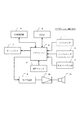
以下、本発明に係るナビゲーション装置の実施の形態を図面に基づいて説明する。図1は実施の形態に係るナビゲーション装置20の構成を示すブロック図である。 Embodiments of a navigation device according to the present invention will be described below with reference to the drawings. FIG. 1 is a block diagram showing a configuration of a navigation device 20 according to the embodiment.
図中1はGPSセンサを示しており、GPSセンサ1は、GPS衛星からの信号を受信して、その信号から位置を算出し、算出した結果をナビゲーションシステム制御用のマイクロコンピュータ(ナビマイコン)2に出力するようになっている。ナビマイコン2にはGPSセンサ1の他にも、ジャイロセンサ3、車速パルス入力部4、ハードディスク装置(HDD)5、操作スイッチ6、ディスプレイ7、情報通信機8、音声合成部9等が接続されている。
In the figure,
ジャイロセンサ3は、車両の向きの変化を検出するセンサでジャイロにより構成され、ナビマイコン2に検出信号を出力し、ナビマイコン2では、このジャイロセンサ3の検出信号を積算して車両の方向を算出するようになっている。車速パルス入力部4は、車両側に設置された車速センサ(図示せず)からの所定走行距離毎に発生するパルス(所定期間におけるパルス数が車速に比例する)からなる車速パルスを取り込み、ノイズ除去、波形整形処理等を行った後ナビマイコン2に車速パルスを出力するようになっている。尚、車両側に設置された車速センサは、車両の駆動系の制御、例えば燃料噴射量制御や点火時期制御等に用いられるもので、車両に既設のものである。この車速センサは、例えば車軸と同期して回転する磁石と、この磁石の回転位置により変化する磁場の状態に応じて接断状態が変わるリードスイッチからなる磁気センサや、車軸と同期して回転する遮蔽板と、この遮蔽板の回転位置によりその光路の遮断状態が変化する受光素子、発光素子からなる光センサ等により構成されている。
The
磁気ディスクを含んで構成され、データの読み書きが可能なHDD5には、地図データ(道路データ、公共交通機関の路線データ、有料道路の料金データ、公共交通機関の料金データ等)が記憶されており、ナビマイコン2からの制御信号に応じて必要なデータを読み込んで、ナビマイコン2に出力するようになっている。また、HDD5には、各地点における高度データ(地点高度データ)が記憶されている。具体的には、高度データとして、地図を適当な大きさの縦横の格子状に区切り、その交点あるいは中心点における絶対位置(例えば緯度・経度)と高さが記憶されている。更に、HDD5には、衛星(あるいは航空機)から撮影された写真(実写画像データ)が記憶されている。具体的には、実写画像データは、地図を適当な大きさの縦横の格子状に区切り、その格子領域毎の画像データがその格子位置データとともに記憶されており、画像における各地点の絶対位置(例えば緯度・経度)が算出できるようになっている。各領域は各領域の実写画像データの表示切り換えをスムーズに行うために周辺部が重なるように作成されている。また、HDD5には、各施設(建築物)位置、施設の内容、建築物の高さ・形状等の施設データが記憶されている。
Map data (road data, public transportation route data, toll road toll data, public transportation toll data, etc.) is stored in the
HDD5は、ナビマイコン2からの制御信号に応じて、地図データの更新データ等、各種データを磁気ディスクに書き込み記憶するように構成されている。HDD5の代わりに、別の実施の形態ではデータの読み書きが可能なDVD−RAM装置や、DVD−ROM装置とメモリ(RAM)の組み合わせ等、種々の記憶装置が用いられ、また、地図データと高度データとがそれぞれ別の記憶装置に記憶されるようになっていてもよい(別種類の記憶装置でも可)。
The
操作スイッチ6は、ナビゲーションシステム操作用のスイッチで、ナビゲーションシステム本体に設置された押しボタンスイッチや、赤外線リモコン等により構成され、ON−OFFスイッチやジョイスティック等の方向指定用スイッチ等を備えている。また、操作スイッチ6としてディスプレイ7の前面に設けられた透明のタッチパネルスイッチ構成されており、ディスプレイ7に対応した座標入力、例えば地図上における位置指定が可能となっている。
The
ナビマイコン2は、ジャイロセンサ3の検出信号と車速パルス入力部4からの車速パルスとから自立方式により自車位置を算出し、そして算出した自車位置とGPSセンサ1からの位置信号とを補完処理して、自車位置を決定するようになっている。また、ナビマイコン2は、この決定された自車位置、操作スイッチ6の操作状態に応じて、必要な地図データ等をHDD5から読み込んだり、目的地までの経路を演算する処理、道路地図や衛星写真、3次元画像等の表示処理等を行い、液晶表示装置で構成されたディスプレイ7に対応する地図、経路、各種案内、そして操作案内表示を行うようになっている。尚、ナビマイコン2には、各種データ、プログラムの記憶、また演算処理のために用いるRAM,ROMが内蔵されている。
The
また、ナビマイコン2には、情報を送受信する情報通信機8が接続されており、ナビマイコン2は情報通信機8が受信した施設情報、ニュース、交通情報、天気予報、娯楽情報等をディスプレイ7に表示させたり、音声合成するために後述の音声合成部9にそのデータを出力するようになっている。また、情報通信機8は携帯電話等の双方向通信機により構成されており、情報提供センターとの双方向通信により、交通情報データ、地図更新データ等、必要な情報を得る構成となっている。
The
音声合成部9はマイコンを含んで構成されており、ナビマイコン2からの文字データを処理して合成音声を生成し、増幅器10に出力し、増幅器10は合成音声を増幅して車室内に設けられたスピーカ11から音声として出力するようになっている。
The
次に、本実施の形態に係るナビゲーション装置20における立体地図画像生成について説明する。尚、立体地図画像表示は、ユーザの立体地図画像表示指示操作があった時等、立体地図画像表示条件が成立した時に行われる。 Next, the 3D map image generation in the navigation device 20 according to the present embodiment will be described. The three-dimensional map image display is performed when a three-dimensional map image display condition is satisfied, such as when a user performs a three-dimensional map image display instruction operation.
立体地図画像の生成は、例えば特開平10−207351号に示されているような透視投影変換処理を、地点高度データと実写画像データに施す方法等により行える。図2は、立体地図画像の生成方法の一例を簡単に示す説明図である。ここでは、説明を簡単にするために、1つの領域の実写画像データを処理対象とし、視点位置を固定した条件で説明するが、処理対象とする領域を変えることにより、また後述する3次元軸(X軸、Y軸、Z軸)の単位長さ、交差角度等を変えることにより様々な形態の画像(視点位置を変えた画像等)が得られる。つまり、ユーザの操作スイッチ6の操作に応じて、これらの値を可変とすることにより、ユーザの所望する立体地図画像が表示される。
A three-dimensional map image can be generated by, for example, a method of performing perspective projection conversion processing as disclosed in Japanese Patent Laid-Open No. 10-207351 on point altitude data and photographed image data. FIG. 2 is an explanatory diagram simply showing an example of a method for generating a three-dimensional map image. Here, for the sake of simplicity, the description will be given under the condition that the real image data of one area is a processing target and the viewpoint position is fixed. However, by changing the processing target area, a three-dimensional axis described later Various types of images (images with different viewpoint positions, etc.) can be obtained by changing the unit length (X-axis, Y-axis, Z-axis), intersection angle, and the like. That is, by changing these values in accordance with the operation of the
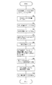
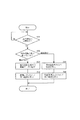
次に実施の形態に係るナビゲーション装置20におけるナビマイコン2の行う立体地図画像の表示処理動作を図3に示したフローチャートに基づいて説明する。
Next, the display processing operation of the three-dimensional map image performed by the
まず、ステップS1では、 図2(A)の実写画像データにおける、各地点(x,y)の色データcを抜き出す処理(第1処理)を行い、その後ステップ2に進む。尚、地点高度データにおいて高さデータを有する地点に対応する各地点についてこの色データの抜き出し処理を行う。 First, in step S1, a process (first process) for extracting color data c at each point (x, y) in the real image data of FIG. 2A is performed, and then the process proceeds to step 2. It should be noted that this color data extraction processing is performed for each point corresponding to a point having height data in the point altitude data.
ステップS2では、地点高度データに基づき、各地点(x,y)について3次元位置データ(x,y,z)化する処理(第2処理)を行い、その後ステップS3に進む。 In step S2, processing (second processing) for converting each point (x, y) into three-dimensional position data (x, y, z) is performed based on the point altitude data, and then the process proceeds to step S3.
ステップS3では、第1処理で抜き出した色データcを第2処理で生成した3次元位置データ(x,y,z)に対応付け、3次元位置色データ(x,y,z,c)を生成する処理(第3処理)を行い、その後ステップ4に進む。 In step S3, the color data c extracted in the first process is associated with the three-dimensional position data (x, y, z) generated in the second process, and the three-dimensional position color data (x, y, z, c) is associated. A process to be generated (third process) is performed, and then the process proceeds to step 4.
ステップS4では、第3処理で生成した3次元位置色データ(x,y,z,c)に基づき、図2(B)で示した3次元座標に対して対応位置に対応色で点描画Cを行い、その後ステップ5に進む。尚、点描画は上書き描画で、点描画順は視点位置(図2(A)の点(Xr,Yr))から遠い点から順に行う。つまり、前景により隠される位置の点描画は上書きされ見えなくなることとなる。
In step S4, based on the three-dimensional position color data (x, y, z, c) generated in the third process, the point drawing C with the corresponding color at the corresponding position with respect to the three-dimensional coordinates shown in FIG. And then go to
続くステップS5〜S9では、建築物(施設)の表示処理が行われるようになっており、建築物の表示処理は、施設データにおける位置データ等に基づいて行われる。 In subsequent steps S5 to S9, a building (facility) display process is performed, and the building display process is performed based on position data or the like in the facility data.
ステップS5では、表示領域にある表示対象の施設の位置データ(Xs,Ys)と地点高度データから、施設を表示する3次元位置データ(Xs,Ys,Zs)を算出する処理(第5処理)を行い、その後ステップS6に進む。 In step S5, a process of calculating three-dimensional position data (Xs, Ys, Zs) for displaying the facility from the position data (Xs, Ys) of the display target facility in the display area and the point altitude data (fifth process) Then, the process proceeds to step S6.
ステップS6では、施設の形状・高さデータに基づき、施設画像を生成する処理を行い、その後ステップS7に進む。ステップS7では、施設の位置データ(Xs,Ys)から実写画像データにおける施設位置を求め、さらに施設の形状・高さデータを参照して実写画像データにおける施設の外形位置における視点位置側の位置を算出する処理を行い、その後ステップS8に進む。 In step S6, a facility image is generated based on the facility shape / height data, and then the process proceeds to step S7. In step S7, the facility position in the live-action image data is obtained from the position data (Xs, Ys) of the facility, and the position on the viewpoint position side in the external position of the facility in the live-action image data is obtained by referring to the shape / height data of the facility. The calculation process is performed, and then the process proceeds to step S8.
ステップS8では、実写画像データにおけるその位置の色データ(あるいはある領域の画像パターン:テクスチャ)を抜き出し、施設画像における施設側面をその抜き出した色で描画する処理(第6処理)を行い、その後ステップ9に進む。同様の方法で施設上面等を色付けしてもよい。また、同じ施設の画像が複数の実写画像データ(異なった領域の実写画像データ)に含まれる場合、その施設が実写画像のより周辺にある方(中心から遠くある方)の実写画像データを利用することにより、施設の側面画像データを作成する。 In step S8, color data (or image pattern: texture of a certain area) in the actual image data is extracted, and a facility side in the facility image is drawn with the extracted color (sixth processing), and then step S8 is performed. Proceed to step 9. The upper surface of the facility may be colored by the same method. In addition, when multiple images of the same facility are included in multiple live-action image data (actual image data in different areas), use the real-image data of the facility that is closer to the periphery (the one that is farther from the center) By doing so, the side image data of the facility is created.
ステップS9では、第5処理で算出した3次元位置データ(Xs,Ys,Zs)に基づき、図2(B)で示した3次元座標に対して対応位置に第6処理で生成した施設画像(図4の施設A,B)を描画する処理を行い、その後ステップS10に進む。 In step S9, based on the three-dimensional position data (Xs, Ys, Zs) calculated in the fifth process, the facility image (generated in the sixth process at the corresponding position with respect to the three-dimensional coordinates shown in FIG. 2B). A process of drawing the facilities A and B) in FIG. 4 is performed, and then the process proceeds to step S10.
ステップS10では、トンネル等の地下構造物を半透明表示する処理を行い、その後処理を終了する。この処理は、ステップS5〜S9の建築物表示処理と略同様の処理で行われるようになっており、ここでは、その説明を省略する。地下構造物については、施設データにその旨を示すデータが付加されており、そのデータより施設が地下構造物の場合には、当該地下構造物を半透明表示する(図4のトンネルUG)。半透明表示方法としては、地下構造物の画像とその前面となる地表面の画像を、ドット単位で千鳥状に交互に表示する方法等がある。 In step S10, a process for semi-transparently displaying an underground structure such as a tunnel is performed, and then the process ends. This process is performed in a process substantially similar to the building display process in steps S5 to S9, and the description thereof is omitted here. For the underground structure, data indicating that fact is added to the facility data. When the facility is an underground structure, the underground structure is displayed translucently (tunnel UG in FIG. 4). As a translucent display method, there is a method of alternately displaying an image of an underground structure and an image of the ground surface that is the front surface in a zigzag pattern in dot units.
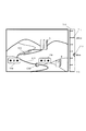
次に、案内経路、自車位置表示等も含めた立体地図画像ナビゲーション表示について説明する。図4は、立体地図画像ナビゲーション表示を示す表示画像図である。 Next, 3D map image navigation display including guidance route, own vehicle position display, etc. will be described. FIG. 4 is a display image diagram showing a three-dimensional map image navigation display.
立体地図画像ナビゲーション表示は、立体地図画像に、目的地までの案内経路NR、自車の現在位置を示す現在位置マークCM、信号機等の交通標識TM等が表示された図である。本実施の形態では、次のような特徴を有している。 The three-dimensional map image navigation display is a diagram in which a guide route NR to the destination, a current position mark CM indicating the current position of the host vehicle, a traffic sign TM such as a traffic light, etc. are displayed on the three-dimensional map image. The present embodiment has the following characteristics.
[特徴1] 自車の現在位置の標高を示す標高ゲージTGが、立体地図画像の横に表示されている。この表示は、縦方向に延びる標高目盛りT1と、自車現在位置の標高を示す指示マークT2から構成されている。また、指示マーク2の色は、標高レベルに応じて変化させられ、より直感的に標高を把握できるようになっている。自車の標高については、自車の現在位置で、地点高度データを検索することにより求められ、この標高データに基づいて標高ゲージTGが表示されるようになっている。
[Feature 1] An altitude gauge TG indicating the altitude of the current position of the host vehicle is displayed beside the three-dimensional map image. This display is composed of an altitude scale T1 extending in the vertical direction and an instruction mark T2 indicating the altitude of the current position of the vehicle. Further, the color of the
[特徴2] 自車の現在位置を示す現在位置マークCMの色は、標高レベル(例えば100m毎)に応じて変化する。これにより、より直感的に現在の標高を把握できるものとなっている。自車の標高については、自車の現在位置で、地点高度データを検索することにより求められ、この標高データと現在位置に基づいて、該当する表示位置に現在位置マークCMが、標高に応じた色で表示されるようになっている。また、自車の現在位置と、経路上における自車の現在位置と前後する位置の標高が求められ、それら標高から現在位置における道の傾斜が算出され、その傾斜に応じて現在位置マークCMの色が変化させられるようになっている。尚、現在位置マークCMの色を、標高、傾斜のどちらで変化させるかは、ユーザによる設定で決められるようになっている。 [Characteristic 2] The color of the current position mark CM indicating the current position of the host vehicle changes according to the altitude level (for example, every 100 m). This makes it possible to grasp the current altitude more intuitively. The altitude of the host vehicle is obtained by searching the point altitude data at the current position of the host vehicle. Based on the altitude data and the current position, the current position mark CM is displayed at the corresponding display position according to the altitude. It is displayed in color. In addition, the current position of the vehicle and the altitude of the current position of the vehicle on the route and the position before and after the vehicle are obtained, and the inclination of the road at the current position is calculated from the elevation, and the current position mark CM is determined according to the inclination. The color can be changed. Note that whether to change the color of the current position mark CM at an altitude or an inclination can be determined by setting by the user.
[特徴3] 道路の色は、その道路の標高レベル(例えば100m毎)に応じて変化する。これにより、より直感的に道路の標高を把握できるものとなっている。道路の標高については、道路の各地点の位置データで、地点高度データを検索することにより求められ、道路の各地点における標高データに基づいて、道路の色が標高に応じた色で表示されるようになっている。また、道路の各地点と、その地点の前後する位置の標高が求められ、それら標高からその地点の傾斜が算出され、その傾斜に応じて道路の色が変化させられるようになっている。尚、道路の色を、標高、傾斜のどちらで変化させるかは、ユーザによる設定で決められるようになっている。 [Characteristic 3] The color of the road changes according to the altitude level (for example, every 100 m) of the road. Thereby, the altitude of the road can be grasped more intuitively. The elevation of the road is obtained by searching the location altitude data from the location data of each location on the road, and the color of the road is displayed in a color corresponding to the elevation based on the elevation data at each location on the road. It is like that. In addition, the altitude of each point on the road and the position before and after the point is obtained, the inclination of the point is calculated from the altitude, and the color of the road is changed according to the inclination. Note that whether the color of the road is to be changed by altitude or slope can be determined by user settings.
[特徴4] 案内経路の色は、その案内経路の標高レベル(例えば100m毎)に応じて変化する。これにより、より直感的に案内経路の標高を把握できるものとなっている。案内経路の標高については、案内経路の各地点の位置データで、地点高度データを検索することにより求められ、案内経路の各地点における標高データに基づいて、案内経路の色を標高に応じた色で表示されるようになっている。また、案内経路の各地点と、その地点の前後する位置の標高が求められ、それら標高からその地点の傾斜が算出され、その傾斜に応じて案内経路の色が変化させられるようになっている。尚、案内経路の色を、標高、傾斜のどちらで変化させるかは、ユーザによる設定で決められるようになっている。また、案内経路と、それ以外の道路との識別性を高めるために、案内経路とそれ以外の道路の表示色は、変化色を含めて同系統の色を使用しない方が好ましい。 [Feature 4] The color of the guide route changes according to the altitude level (for example, every 100 m) of the guide route. Thereby, the elevation of the guide route can be grasped more intuitively. The altitude of the guide route is obtained by searching the location altitude data from the position data of each point on the guide route, and the color of the guide route according to the altitude based on the altitude data at each point of the guide route. Is displayed. In addition, the elevation of each point of the guide route and the position before and after the point is obtained, the inclination of the point is calculated from the elevation, and the color of the guide route can be changed according to the inclination. . Note that whether to change the color of the guide route at an altitude or an inclination can be determined by setting by the user. Moreover, in order to improve the discriminability between the guide route and other roads, it is preferable not to use the same color as the display color of the guide route and other roads including the change color.
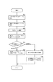
次にナビマイコン2の行う自車位置表示処理動作を図5に示したフローチャートに基づいて説明する。本処理動作は、自車の現在位置が検出されるタイミングで実行される。
Next, the vehicle position display processing operation performed by the
まず、ステップ11では、自車の現在位置データを取得する処理を行い、その後ステップS12に進む。ステップS12では、取得した自車の現在位置における地点高度データを探索して、現在位置の標高データを抽出する処理を行い、その後ステップS13に進む。ステップS13では、抽出された標高データに基づいて標高レベルを判定する処理を行い、その後ステップ14に進む。ステップS14では、判定された標高レベルに応じた色の指示マーク2を該当する目盛り位置に表示する処理を行い、その後ステップS15に進む。
First, in
ステップS15では、現在位置マークCMの色の表示設定を判断し、標高設定であると判断すればステップS16に進む。ステップS16では、現在位置マークCMをステップS13で判定された標高レベルに応じた色で表示する処理を行い、その後処理を終了する。 In step S15, the display setting of the color of the current position mark CM is determined. If it is determined that the altitude setting is set, the process proceeds to step S16. In step S16, a process for displaying the current position mark CM in a color corresponding to the altitude level determined in step S13 is performed, and then the process ends.
一方、ステップS15において、現在位置マークCMの色の表示設定が傾斜設定であると判断すればステップS17に進む。ステップS17では、現在位置における道の傾斜を算出する処理を行い、その後ステップS18に進む。ステップS18では、現在位置マークCMを傾斜角度に応じた色で表示する処理を行い、その後処理を終了する。 On the other hand, if it is determined in step S15 that the display setting of the color of the current position mark CM is tilt setting, the process proceeds to step S17. In step S17, a process of calculating the slope of the road at the current position is performed, and then the process proceeds to step S18. In step S18, a process of displaying the current position mark CM in a color corresponding to the tilt angle is performed, and then the process ends.
次にナビマイコン2の行う道路表示処理動作を図6に示したフローチャートに基づいて説明する。本処理動作は、立体地図画像の表示領域が切り替えられるタイミングで実行される。
Next, the road display processing operation performed by the
まずステップS21では、縮尺の変更や移動等に伴い立体地図画像の表示領域が切り替えられたか否かを判断し、立体地図画像の表示領域が切り替えられていないと判断すればステップS21に戻る一方、立体地図画像の表示領域が切り替えられたと判断すればステップS22に進む。ステップS22では、立体地図画像に表示される道路の色の表示設定を判断し、標高設定であると判断すればステップS23に進む。ステップS23では、道路の各地点の位置データに基づいて地点高度データを探索し、表示される道路の各地点の標高データを抽出する処理を行い、その後ステップS24に進む。ステップS24では、抽出された道路の各地点の標高データに基づいて道路の色を標高に応じた色で表示する処理を行い、その後処理を終了する。 First, in step S21, it is determined whether or not the display area of the 3D map image has been switched due to a change in scale, movement, or the like. If it is determined that the display area of the 3D map image has not been switched, the process returns to step S21. If it is determined that the display area of the three-dimensional map image has been switched, the process proceeds to step S22. In step S22, the display setting of the color of the road displayed on the three-dimensional map image is determined. If it is determined that the altitude setting is set, the process proceeds to step S23. In step S23, the point altitude data is searched based on the position data of each point on the road, the altitude data of each point on the road to be displayed is extracted, and then the process proceeds to step S24. In step S24, a process for displaying the color of the road in a color corresponding to the altitude is performed based on the extracted altitude data of each point of the road, and then the process ends.
一方、ステップS22において、道路の色の表示設定が傾斜設定であると判断すればステップS25に進む。ステップS25では、道路の各地点の傾斜を算出する処理を行い、その後ステップS26に進む。ステップS26では、算出された道路の各地点の傾斜データに基づいて道路の色を傾斜角度に応じた色で表示する処理を行い、その後処理を終了する。 On the other hand, if it is determined in step S22 that the display setting of the road color is an inclination setting, the process proceeds to step S25. In step S25, a process of calculating the slope of each point on the road is performed, and then the process proceeds to step S26. In step S26, a process of displaying the color of the road in a color corresponding to the inclination angle is performed based on the calculated inclination data of each point of the road, and then the process ends.
次にナビマイコン2の行う案内経路表示処理動作を図7に示したフローチャートに基づいて説明する。本処理動作は、立体地図画像の表示領域が切り替えられるタイミングで実行される。
Next, the guidance route display processing operation performed by the
まずステップS31では、縮尺の変更や移動等に伴い立体地図画像の表示領域が切り替えられたか否かを判断し、立体地図画像の表示領域が切り替えられていないと判断すればステップS31に戻る一方、立体地図画像の表示領域が切り替えられたと判断すればステップS32に進む。ステップS32では、立体地図画像に表示される案内経路の色の表示設定を判断し、標高設定であると判断すればステップS33に進む。ステップS33では、案内経路の各地点の位置データに基づいて地点高度データを探索し、表示される案内経路の各地点の標高データを抽出する処理を行い、その後ステップS34に進む。ステップS34では、抽出された案内経路の各地点の標高データに基づいて案内経路の色を標高に応じた色で表示する処理を行い、その後処理を終了する。 First, in step S31, it is determined whether or not the display area of the three-dimensional map image has been switched due to a change or movement of the scale. If it is determined that the display area of the three-dimensional map image has not been switched, the process returns to step S31. If it is determined that the display area of the three-dimensional map image has been switched, the process proceeds to step S32. In step S32, the display setting of the color of the guide route displayed on the three-dimensional map image is determined. If it is determined that the altitude setting is set, the process proceeds to step S33. In step S33, a process for searching for point altitude data based on the position data of each point on the guide route and extracting elevation data of each point on the displayed guide route is performed, and then the process proceeds to step S34. In step S34, a process of displaying the color of the guide route in a color corresponding to the altitude is performed based on the elevation data of each point of the extracted guide route, and then the process ends.
一方、ステップS32において、案内経路の色の表示設定が傾斜設定であると判断すればステップS35に進む。ステップS35では、案内経路の各地点の傾斜を算出する処理を行い、その後ステップS36に進む。ステップS36では、算出された案内経路の各地点の傾斜データに基づいて案内経路の色を傾斜角度に応じた色で表示する処理を行い、その後処理を終了する。 On the other hand, if it is determined in step S32 that the display setting of the color of the guide route is tilt setting, the process proceeds to step S35. In step S35, the process of calculating the inclination of each point on the guide route is performed, and then the process proceeds to step S36. In step S36, a process of displaying the color of the guidance route in a color corresponding to the inclination angle is performed based on the calculated inclination data of each point of the guidance route, and then the process is terminated.
以上のように本実施の形態によれば、地点高度データと実写画像データを用いて、リアリティの高い立体地図表示ができる。また、経路案内において、道路や案経経路、自車現在位置等の標高や傾斜を容易に把握できる。 As described above, according to the present embodiment, it is possible to display a stereoscopic map with high reality by using point altitude data and photographed image data. Further, in route guidance, it is possible to easily grasp the altitude and inclination of roads, draft routes, current vehicle positions, and the like.
20 ナビゲーション装置
2 ナビマイコン
4 車速パルス入力部
5 HDD(ハードディスク)
6 操作スイッチ
7 ディスプレイ
20
6
Claims (15)
各地点における高度データを記憶する地点高度記憶手段と、
上空より撮影した地形の画像データを記憶する画像記憶手段と、
前記地点高度記憶手段に記憶された高度データと前記画像記憶手段に記憶された画像データに基づいて立体地図画像を生成する立体地図画像生成手段と、
前記立体地図画像生成手段により生成された立体地図画像を表示する表示手段とを備えていることを特徴とするナビゲーション装置。 In a navigation device that provides route guidance to a destination,
Point altitude storage means for storing altitude data at each point;
Image storage means for storing terrain image data taken from above;
3D map image generation means for generating a 3D map image based on altitude data stored in the point altitude storage means and image data stored in the image storage means;
A navigation device comprising display means for displaying a three-dimensional map image generated by the three-dimensional map image generation means.
該建築物記憶手段に記憶された建築物のデータに基づいて立体地図画像の該当する位置に建築物を表示する建築物表示手段とを備えていることを特徴とする請求項1記載のナビゲーション装置。 Building storage means for storing building data;
2. The navigation apparatus according to claim 1, further comprising: a building display means for displaying the building at a corresponding position in the three-dimensional map image based on the building data stored in the building storage means. .
前記建築物表示手段が、前記建築物記憶手段に記憶された建築物の高さデータと、前記地点高度記憶手段に記憶された建築物の位置における地点高度データに基づいて建築物の立体表示を行うものであることを特徴とする請求項2記載のナビゲーション装置。 The building storage means also stores building height data as building data,
The building display means performs a three-dimensional display of the building based on the building height data stored in the building storage means and the point height data at the position of the building stored in the point height storage means. The navigation apparatus according to claim 2, wherein the navigation apparatus performs the operation.
前記建築物表示手段が、建築物の立体表示を行う際に建築物の側面を前記画像パターン抽出手段により抽出された画像パターンで描画処理するものであることを特徴とする請求項3記載のナビゲーション装置。 Image pattern extraction means for extracting a side image pattern of a building based on image data stored in the image storage means;
4. The navigation according to claim 3, wherein the building display means renders a side surface of the building with the image pattern extracted by the image pattern extraction means when performing stereoscopic display of the building. apparatus.
前記立体地図画像生成手段が、前記視点位置設定手段により設定された視点位置に応じて画像生成処理を行うものであることを特徴とする請求項1〜5のいずれかの項に記載のナビゲーション装置。 Equipped with viewpoint position setting means for setting the viewpoint position of the three-dimensional map,
The navigation apparatus according to claim 1, wherein the three-dimensional map image generation unit performs image generation processing according to the viewpoint position set by the viewpoint position setting unit. .
該現在位置検出手段により検出された車両の現在位置に基づいて立体地図の該当位置に現在位置マークを表示する現在位置マーク表示手段を備えていることを特徴とする請求項1〜6のいずれかの項に記載のナビゲーション装置。 Current position detecting means for detecting the current position;
7. A current position mark display means for displaying a current position mark at a corresponding position of the three-dimensional map based on the current position of the vehicle detected by the current position detection means. The navigation device according to the section.
Priority Applications (1)
| Application Number | Priority Date | Filing Date | Title |
|---|---|---|---|
| JP2004002474A JP2005195475A (en) | 2004-01-07 | 2004-01-07 | Navigation system |
Applications Claiming Priority (1)
| Application Number | Priority Date | Filing Date | Title |
|---|---|---|---|
| JP2004002474A JP2005195475A (en) | 2004-01-07 | 2004-01-07 | Navigation system |
Publications (2)
| Publication Number | Publication Date |
|---|---|
| JP2005195475A true JP2005195475A (en) | 2005-07-21 |
| JP2005195475A5 JP2005195475A5 (en) | 2006-12-21 |
Family
ID=34817660
Family Applications (1)
| Application Number | Title | Priority Date | Filing Date |
|---|---|---|---|
| JP2004002474A Pending JP2005195475A (en) | 2004-01-07 | 2004-01-07 | Navigation system |
Country Status (1)
| Country | Link |
|---|---|
| JP (1) | JP2005195475A (en) |
Cited By (10)
| Publication number | Priority date | Publication date | Assignee | Title |
|---|---|---|---|---|
| JP2009229354A (en) * | 2008-03-25 | 2009-10-08 | Denso Corp | Map display |
| JP2010002362A (en) * | 2008-06-23 | 2010-01-07 | Xanavi Informatics Corp | Navigation device |
| EP2505964A2 (en) | 2011-03-31 | 2012-10-03 | Aisin AW Co., Ltd. | Movement guidance display system, movement guidance display method, and computer program |
| JP2015036824A (en) * | 2013-08-12 | 2015-02-23 | 株式会社ジオ技術研究所 | Three-dimensional map display system |
| WO2015141301A1 (en) * | 2014-03-19 | 2015-09-24 | 株式会社ジオ技術研究所 | Three-dimensional-map display system |
| KR20160065721A (en) * | 2014-12-01 | 2016-06-09 | 팅크웨어(주) | Electronic apparatus, control method of electronic apparatus, computer program and computer readable recording medium |
| JP2016170308A (en) * | 2015-03-13 | 2016-09-23 | 株式会社ゼンリンデータコム | Information processing apparatus, map display system, and program |
| CN107338712A (en) * | 2016-12-29 | 2017-11-10 | 沧州渤海新区辰禾工程有限公司 | A kind of roadbed is built with distance pole and roadbed construction method |
| JP2020140487A (en) * | 2019-02-28 | 2020-09-03 | トヨタ自動車株式会社 | Processing device, processing method, and program |
| JP2021157018A (en) * | 2020-03-26 | 2021-10-07 | 株式会社アイシン | Map display system and map display program |
-
2004
- 2004-01-07 JP JP2004002474A patent/JP2005195475A/en active Pending
Cited By (19)
| Publication number | Priority date | Publication date | Assignee | Title |
|---|---|---|---|---|
| JP2009229354A (en) * | 2008-03-25 | 2009-10-08 | Denso Corp | Map display |
| JP2010002362A (en) * | 2008-06-23 | 2010-01-07 | Xanavi Informatics Corp | Navigation device |
| EP2505964A2 (en) | 2011-03-31 | 2012-10-03 | Aisin AW Co., Ltd. | Movement guidance display system, movement guidance display method, and computer program |
| US20120253666A1 (en) * | 2011-03-31 | 2012-10-04 | Aisin Aw Co., Ltd. | Movement guidance display system, movement guidance display method, and computer program |
| CN102735240A (en) * | 2011-03-31 | 2012-10-17 | 爱信艾达株式会社 | Movement guidance display system, movement guidance display method, and computer program |
| US9741164B2 (en) | 2013-08-12 | 2017-08-22 | Geo Technical Laboratory Co., Ltd. | 3D map display system |
| JP2015036824A (en) * | 2013-08-12 | 2015-02-23 | 株式会社ジオ技術研究所 | Three-dimensional map display system |
| EP3051498A4 (en) * | 2014-03-19 | 2017-05-31 | Geo Technical Laboratory Co., Ltd. | Three-dimensional-map display system |
| JP2015179346A (en) * | 2014-03-19 | 2015-10-08 | 株式会社ジオ技術研究所 | Three-dimensional map display system |
| CN105474269A (en) * | 2014-03-19 | 2016-04-06 | 吉欧技术研究所股份有限公司 | Three-dimensional-map display system |
| WO2015141301A1 (en) * | 2014-03-19 | 2015-09-24 | 株式会社ジオ技術研究所 | Three-dimensional-map display system |
| KR20160065721A (en) * | 2014-12-01 | 2016-06-09 | 팅크웨어(주) | Electronic apparatus, control method of electronic apparatus, computer program and computer readable recording medium |
| KR102406489B1 (en) | 2014-12-01 | 2022-06-10 | 현대자동차주식회사 | Electronic apparatus, control method of electronic apparatus, computer program and computer readable recording medium |
| JP2016170308A (en) * | 2015-03-13 | 2016-09-23 | 株式会社ゼンリンデータコム | Information processing apparatus, map display system, and program |
| CN107338712A (en) * | 2016-12-29 | 2017-11-10 | 沧州渤海新区辰禾工程有限公司 | A kind of roadbed is built with distance pole and roadbed construction method |
| JP2020140487A (en) * | 2019-02-28 | 2020-09-03 | トヨタ自動車株式会社 | Processing device, processing method, and program |
| US11592303B2 (en) | 2019-02-28 | 2023-02-28 | Toyota Jidosha Kabushiki Kaisha | Processing apparatus, processing method, and program |
| JP2021157018A (en) * | 2020-03-26 | 2021-10-07 | 株式会社アイシン | Map display system and map display program |
| JP7417198B2 (en) | 2020-03-26 | 2024-01-18 | 株式会社アイシン | Map display system, map display program |
Similar Documents
| Publication | Publication Date | Title |
|---|---|---|
| JP3375258B2 (en) | Map display method and device, and navigation device provided with the device | |
| KR100745116B1 (en) | Stereoscopic map-display method and navigation system using the method | |
| EP1085299B1 (en) | Navigation apparatus | |
| JP3501390B2 (en) | Car navigation system | |
| CN101363739B (en) | Navigation apparatus and navigation program | |
| CN101573590A (en) | Navigation device and method for displaying navigation information | |
| JP2002168634A (en) | Display method for three-dimensional map of on-vehicle navigation system | |
| MX2007015348A (en) | Navigation device with camera-info. | |
| WO2006092853A1 (en) | Map display device and map display method | |
| JP2008014754A (en) | Navigation apparatus | |
| JP2009236843A (en) | Navigation device, navigation method, and navigation program | |
| JP2005195475A (en) | Navigation system | |
| JP2006349964A (en) | Map display apparatus for portable device | |
| JP2004233333A (en) | Stereoscopic display method for navigation, and navigation device | |
| JP3642776B2 (en) | Map display method of navigation device and navigation device | |
| JP2001273526A (en) | Stereoscopic map display device | |
| JP2005283630A (en) | Electronic apparatus having navigation function, and night scene map display method | |
| RU2375756C2 (en) | Navigation device with information received from camera | |
| JPH09237037A (en) | Map display device | |
| JPH10332396A (en) | Navigation device | |
| JP4381205B2 (en) | Navigation device and map display method in the device | |
| JP2000207577A (en) | Map sterescopice display device | |
| JP2007178378A (en) | Car navigation device | |
| JP3619076B2 (en) | Navigation device | |
| KR20080019690A (en) | Navigation device with camera-info |
Legal Events
| Date | Code | Title | Description |
|---|---|---|---|
| A521 | Written amendment |
Effective date: 20061106 Free format text: JAPANESE INTERMEDIATE CODE: A523 |
|
| A621 | Written request for application examination |
Effective date: 20061107 Free format text: JAPANESE INTERMEDIATE CODE: A621 |
|
| A977 | Report on retrieval |
Free format text: JAPANESE INTERMEDIATE CODE: A971007 Effective date: 20090122 |
|
| A131 | Notification of reasons for refusal |
Effective date: 20090127 Free format text: JAPANESE INTERMEDIATE CODE: A131 |
|
| A02 | Decision of refusal |
Free format text: JAPANESE INTERMEDIATE CODE: A02 Effective date: 20090616 |