JP2005190785A - Non-aqueous electrolyte secondary battery - Google Patents
Non-aqueous electrolyte secondary battery Download PDFInfo
- Publication number
- JP2005190785A JP2005190785A JP2003429647A JP2003429647A JP2005190785A JP 2005190785 A JP2005190785 A JP 2005190785A JP 2003429647 A JP2003429647 A JP 2003429647A JP 2003429647 A JP2003429647 A JP 2003429647A JP 2005190785 A JP2005190785 A JP 2005190785A
- Authority
- JP
- Japan
- Prior art keywords
- positive electrode
- active material
- material layer
- electrode active
- separator
- Prior art date
- Legal status (The legal status is an assumption and is not a legal conclusion. Google has not performed a legal analysis and makes no representation as to the accuracy of the status listed.)
- Pending
Links
Images


Classifications
-
- Y—GENERAL TAGGING OF NEW TECHNOLOGICAL DEVELOPMENTS; GENERAL TAGGING OF CROSS-SECTIONAL TECHNOLOGIES SPANNING OVER SEVERAL SECTIONS OF THE IPC; TECHNICAL SUBJECTS COVERED BY FORMER USPC CROSS-REFERENCE ART COLLECTIONS [XRACs] AND DIGESTS
- Y02—TECHNOLOGIES OR APPLICATIONS FOR MITIGATION OR ADAPTATION AGAINST CLIMATE CHANGE
- Y02E—REDUCTION OF GREENHOUSE GAS [GHG] EMISSIONS, RELATED TO ENERGY GENERATION, TRANSMISSION OR DISTRIBUTION
- Y02E60/00—Enabling technologies; Technologies with a potential or indirect contribution to GHG emissions mitigation
- Y02E60/10—Energy storage using batteries
-
- Y—GENERAL TAGGING OF NEW TECHNOLOGICAL DEVELOPMENTS; GENERAL TAGGING OF CROSS-SECTIONAL TECHNOLOGIES SPANNING OVER SEVERAL SECTIONS OF THE IPC; TECHNICAL SUBJECTS COVERED BY FORMER USPC CROSS-REFERENCE ART COLLECTIONS [XRACs] AND DIGESTS
- Y02—TECHNOLOGIES OR APPLICATIONS FOR MITIGATION OR ADAPTATION AGAINST CLIMATE CHANGE
- Y02P—CLIMATE CHANGE MITIGATION TECHNOLOGIES IN THE PRODUCTION OR PROCESSING OF GOODS
- Y02P70/00—Climate change mitigation technologies in the production process for final industrial or consumer products
- Y02P70/50—Manufacturing or production processes characterised by the final manufactured product
Landscapes
- Cell Separators (AREA)
- Secondary Cells (AREA)
Abstract
Description
本発明は、電池の高容量化と安全性の向上を目的とした非水電解質二次電池の改良に関する。 The present invention relates to an improvement in a non-aqueous electrolyte secondary battery for the purpose of increasing the battery capacity and improving safety.
リチウムイオン二次電池に代表される非水電解質二次電池は、高いエネルギー密度を有しかつ高容量であるので、移動情報端末等の駆動電源として有用である。 A non-aqueous electrolyte secondary battery represented by a lithium ion secondary battery has a high energy density and a high capacity, and thus is useful as a driving power source for mobile information terminals and the like.
例えば、正極板と負極板とを、セパレータを介して巻回した巻回型の電極体を用いたリチウム二次電池は、正負極の対向面積が大きく、大電流を取り出しやすいことから、上記移動情報端末等に広く用いられている。 For example, a lithium secondary battery using a wound-type electrode body in which a positive electrode plate and a negative electrode plate are wound via a separator has a large opposing area between the positive and negative electrodes, and it is easy to take out a large current. Widely used in information terminals and the like.
このような巻回型電極体は、正負極の間にセパレータを介在させ、かつ各極板とセパレータとの幅方向の中心線を一致させて重ね合わせた後、巻き取り機により巻回することによって作製される。この巻回工程は精密に制御されているものの、微少な巻きズレが生じる可能性がある。図6に示すように、巻きズレ(L1、L2)が生じると、正極板(正極活物質層)201の端部には対向する負極板(負極活物質層)202が存在しない負極非対向正極領域205が生じる。この状態では、負極非対向正極領域205からのリチウムイオン204の移動が負極板202の端部(図6の○で囲んだ部分)に集中し、負極板202の端部が吸蔵できるリチウムイオン量を超える。このため、当該端部にリチウムデンドライトが析出し、これがセパレータを貫通し、正極と導通して内部短絡を引き起こす。
In such a wound electrode body, a separator is interposed between the positive and negative electrodes, and the center lines in the width direction of each electrode plate and the separator are overlapped with each other and then wound by a winder. It is produced by. Although this winding process is precisely controlled, there is a possibility that a slight winding deviation may occur. As shown in FIG. 6, when winding deviation (
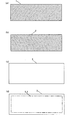
そこで、図4(a)〜図4(d)に示すように、負極板102のサイズを正極板101よりも大きく、且つセパレータ103のサイズを負極板102よりも大きく設計することにより、図5に示すように巻きズレ(L1<L2)が生じても負極非対向正極領域が生じないようにして、リチウムの析出による内部短絡を防止することがなされている。
4A to 4D, the size of the
しかし、この技術では正極板の正極活物質量が小さくなるので、電池のさらなる高容量化に対する要望に応えることができない。
他方、正極板のサイズを負極板のサイズまで大きくすると、上述した理由により安全性に問題が生じる。
However, since the amount of the positive electrode active material in the positive electrode plate is reduced by this technique, it is not possible to meet the demand for higher capacity of the battery.
On the other hand, when the size of the positive electrode plate is increased to the size of the negative electrode plate, a problem arises in safety for the reason described above.
そこで、負極でのリチウムの析出を防止するため、セパレータの一部を閉塞し部分的にリチウムイオンの透過を阻止する技術が提案されている(特許文献1〜3)。
Therefore, in order to prevent lithium deposition on the negative electrode, a technique has been proposed in which a part of the separator is blocked to partially prevent lithium ions from passing therethrough (
特許文献1は、セパレータを多孔質体で形成し、該セパレータの正極板の周縁部に対面している部分の孔を潰しリチウムイオンの透過を阻止することにより安全性を高めようとする技術である。しかし、この技術は、正極板の周縁部の充放電反応を抑制するものであるので電池容量を低下させることになる。
特許文献2には、負極側リード線接続部と正極板の他方の端部との間の部分に、両者におけるリチウムイオンの移動を阻止する無孔質の阻止部分を形成する開示されている。この技術は負極側リード線接続部にリチウムが析出することを防止するための技術である。よって、活物質量を多くするという観点からの検討はなされていない。
特許文献3には、セパレータの端縁部の気孔率を各電極間に挟持されたセパレータの中央部の気孔率よりも相対的に低く設定する技術が開示されている。しかし、この技術は、セパレータの端縁部に剥がれ落ちた活物質がセパレータの端縁部に侵入することを阻止し、セパレータの導電性が高まらないようにする技術である。よって、活物質量を多くするという観点からの検討はなされていない。
発明者らは、上記問題を解決するために鋭意研究を行ったところ、正極板のサイズを負極板のサイズと同一としても、リチウムイオンを透過させないようにセパレータを予め所定の位置にセパレータを閉塞した透過阻止領域を形成することにより、高容量で且つ安全性の高い電池が得られることを見いだした。 The inventors have conducted intensive research to solve the above problems, and even if the size of the positive electrode plate is the same as the size of the negative electrode plate, the separator is previously blocked at a predetermined position so as not to transmit lithium ions. It was found that a battery having a high capacity and high safety can be obtained by forming the permeation blocking region.
本発明は以上の知見に基づき完成されたものであって、電池容量が大きく、安全性に優れた非水電解質二次電池を提供することを目的とする。 The present invention has been completed based on the above findings, and an object thereof is to provide a nonaqueous electrolyte secondary battery having a large battery capacity and excellent safety.
本発明は、正極集電体上に塗布されてなる正極活物質層を有する帯状の正極板と、負極活物質層を有する帯状の負極板と、前記正負極板間に介装され、リチウムイオンを透過させる微細孔を有する帯状のセパレータと、からなる電極体と、非水電解質と、を備える非水電解質二次電池において、前記正極活物質層のサイズと前記負極活物質層のサイズとが実質的に同一であり、前記セパレータのサイズが前記正極活物質層のサイズよりも大きく、前記セパレータが前記微細孔を予め閉塞してなる透過阻止領域31を有し、前記正極集電体の前記セパレータと直接対向する正極活物質層中の正極活物質質量をm(g/m2)とし、前記正極活物質層を覆うように前記セパレータと前記正極板とを重ね合わせたとき、前記正極活物質層の外周線3aと前記透過阻止領域31の内周線3bとの直線距離t1が0.5≦t1≦12.3−0.03m(mm)を満たし、前記正極外周線3aと前記透過阻止領域31の外周線3cとの直線距離t2が0.5≦t2(mm)を満たしている、ことを特徴とする。
The present invention provides a strip-like positive electrode plate having a positive electrode active material layer coated on a positive electrode current collector, a strip-like negative electrode plate having a negative electrode active material layer, and a lithium ion interposed between the positive and negative electrode plates. In a non-aqueous electrolyte secondary battery comprising a strip-shaped separator having fine pores that permeate, an electrode body, and a non-aqueous electrolyte, the size of the positive electrode active material layer and the size of the negative electrode active material layer are Substantially the same, the separator has a size larger than the size of the positive electrode active material layer, and the separator has a
ここで、「実質的に同一」とは完全に同一なものを意味するのではなく、製造上の誤差があってもよいことを意味し、誤差の範囲としては好ましくは5%以下、より好ましくは3%以下、さらに好ましくは1%以下とする。 Here, “substantially the same” does not mean completely the same thing, but means that there may be a manufacturing error, and the error range is preferably 5% or less, more preferably Is 3% or less, more preferably 1% or less.
本発明はまた、前記セパレータの透過阻止領域が、電極体作製前にセパレータの融点以上に加熱して、セパレータの微細孔を溶融することにより形成されたものである、とすることができる。 According to the present invention, the permeation prevention region of the separator may be formed by heating the separator to a melting point or higher before melting the electrode body to melt the fine pores of the separator.
本発明によると、図1、2に示すように、前記正極活物質層の外周線3aを中心としてセパレータの内側及び外側の領域に透過阻止領域31が形成されている。このため、巻きズレが生じた場合、負極非対向正極領域5のリチウムイオン4は、充電時に図3の矢印で示すように当該透過阻止領域31を迂回して正極板(正極活物質層)1から負極板(負極活物質層)2に移動する。このリチウムイオン4の一部は、セパレータ3を透過した後、負極板の端部に到達する前に負極板に吸蔵される。したがって、負極板の端部でのリチウムの析出が抑制され、高容量で且つ安全性に優れた電池が得られる。
According to the present invention, as shown in FIGS. 1 and 2,
ここで、正極活物質層の外周線3aと透過阻止領域内周線3bとの直線距離t1及び正極活物質層の外周線3aと透過阻止領域外周線3cとの直線距離t2が0.5mm以上であることが好ましい。他方、図8に示すように正極活物質層の外周線403aと透過阻止領域内周線403bとの直線距離t1が0.5mmよりも小さいと、透過阻止領域の大きさが過小であり、負極板の端部での過剰なリチウムイオンの吸蔵を防止する効果が小さく、負極板の端部にリチウムが析出する。正極活物質層の外周線と透過阻止領域外周線との直線距離t2が0.5mmよりも小さい場合においても同様である。
Here, the linear distance t1 between the outer
また、セパレータと直接対向する正極活物質層中の正極活物質質量をm(g/m2)としたとき、正極活物質層の外周線3aと透過阻止領域内周線3bとの直線距離t1が12.3−0.03m以下であることが好ましい。他方、図7に示すようにt1が12.3−0.03mより大きいと、透過阻止領域331と対向している正極板301からのリチウムイオン304の多くが負極板302の端部に到達する前に、透過阻止領域内周線303b近傍の負極板302に過剰のリチウムイオン304吸蔵されて、当該部分でリチウムが析出するという問題が新たに生じてしまう。
Further, when the mass of the positive electrode active material in the positive electrode active material layer directly facing the separator is m (g / m 2 ), the linear distance t1 between the outer
また、t2の上限は特に規制されないが、セパレータのサイズが大きくなると体積エネルギー密度が低下することに留意する必要がある。 Moreover, although the upper limit of t2 is not particularly restricted, it should be noted that the volume energy density decreases as the separator size increases.
また、正極活物質層のサイズ及び正極活物質質量が設計されると、それに従い透過阻止領域の位置、サイズも決定されるので、電極体作製前に当該部分をセパレータの融点以上に加熱するという簡便な手段によって透過阻止領域を作製できる。したがって、生産しやすい。 In addition, when the size of the positive electrode active material layer and the mass of the positive electrode active material are designed, the position and size of the permeation blocking region are also determined accordingly, so that the portion is heated to the melting point or more of the separator before the electrode body is manufactured. The permeation blocking region can be produced by simple means. Therefore, it is easy to produce.
本発明を実施するための最良の形態を、実施の形態に基づいて以下に詳細に説明する。本発明は下記実施の形態に何ら限定されるものではなく、その要旨を変更しない範囲において適宜変更して実施することができる。 The best mode for carrying out the present invention will be described in detail below based on the embodiments. The present invention is not limited to the following embodiments, and can be implemented with appropriate modifications within a range that does not change the gist thereof.
(実施の形態)
以下、本発明に係る電池の作製方法について説明する。
(Embodiment)
Hereinafter, a method for manufacturing a battery according to the present invention will be described.
〈正極の作製〉
コバルト酸リチウム(LiCoO2)からなる正極活物質90質量部と、アセチレンブラックからなる導電剤5質量部と、ポリビニリデンフルオライド(PVdF)からなる結着剤5質量部と、N−メチル−2−ピロリドン(NMP)とを混合し、活物質スラリーとした。
<Preparation of positive electrode>
90 parts by mass of a positive electrode active material composed of lithium cobaltate (LiCoO 2 ), 5 parts by mass of a conductive agent composed of acetylene black, 5 parts by mass of a binder composed of polyvinylidene fluoride (PVdF), and N-methyl-2 -Pyrrolidone (NMP) was mixed to obtain an active material slurry.
この活物質スラリーをドクターブレードにより厚み20μmのアルミニウム箔からなる正極芯体の両面に均一に塗布した後、乾燥機中を通過させて乾燥することにより、スラリー作製時に必要であった有機溶媒を除去した。次いで、この極板を所定の充填密度となるようにロールプレス機により圧延して裁断することにより正極板1を作製した。
The active material slurry is uniformly applied to both surfaces of a positive electrode core made of an aluminum foil having a thickness of 20 μm by a doctor blade, and then passed through a dryer to be dried, thereby removing the organic solvent necessary for slurry preparation. did. Subsequently, the
〈負極の作製〉
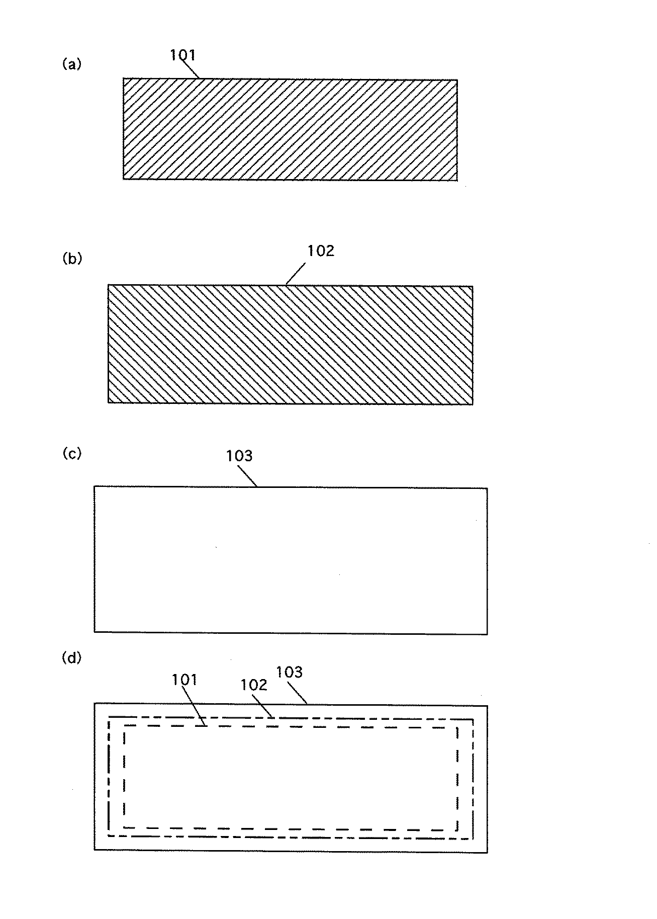
黒鉛からなる負極活物質90質量部と、ポリビニリデンフルオライド(PVdF)からなる結着剤10質量部と、N−メチル−2−ピロリドン(NMP)とを混合して活物質スラリーとした。この活物質スラリーをドクターブレードにより厚み20μmの銅箔からなる負極芯体の両面に均一に塗布した後、乾燥機中を通過させて乾燥することにより、スラリー作製時に必要であった有機溶媒を除去した。次いで、この極板を厚みが0.14mmになるようにロールプレス機により圧延して裁断することにより負極板2を作製した。なお、図1(a)、図1(b)、図1(d)に示すように、上記正極板(正極活物質層)1と上記負極板(負極活物質層)2のサイズは同一とした。
<Preparation of negative electrode>
An active material slurry was prepared by mixing 90 parts by mass of a negative electrode active material made of graphite, 10 parts by mass of a binder made of polyvinylidene fluoride (PVdF), and N-methyl-2-pyrrolidone (NMP). This active material slurry is uniformly applied to both sides of a negative electrode core made of a copper foil having a thickness of 20 μm by a doctor blade, and then passed through a dryer to dry, thereby removing an organic solvent necessary for slurry preparation. did. Next, the electrode plate was rolled and cut with a roll press so that the thickness was 0.14 mm, whereby a
〈セパレータの作製〉
ポリオレフィン製微多孔膜を必要なサイズに裁断し、そのうち一定部分を140℃のホットプレートに10秒押しあてることによって微多孔を溶融して閉塞させ、図2に示す透過阻止領域31が形成されたセパレータ3を作製した。なお、図1(c)、図1(d)に示すように、上記セパレータ3のサイズは正極板1のサイズ及び負極板2のサイズより大きくした。
<Preparation of separator>
The polyolefin microporous membrane was cut to a required size, and a certain portion of the membrane was pressed against a hot plate at 140 ° C. for 10 seconds to melt and close the micropore, thereby forming the
〈電解質の調製〉
エチレンカーボネートとジエチルカーボネートとを体積比5:5となるように混合した混合溶媒に、電解質塩としてLiPF6を1M(モル/リットル)となるよう溶解し、電解液を作製した。
<Preparation of electrolyte>
LiPF 6 as an electrolyte salt was dissolved in a mixed solvent in which ethylene carbonate and diethyl carbonate were mixed so as to have a volume ratio of 5: 5 to 1 M (mol / liter) to prepare an electrolytic solution.
〈電極体の作製〉
上記で作製した正負極板の間に上記セパレータを介在させ、かつ各極板の幅方向の中心線を一致させて重ね合わせた。この後、巻き取り機により巻回し、最外周をテープ止めすることにより渦巻状電極体を作製した。
<Production of electrode body>
The separator was interposed between the positive and negative electrode plates produced above, and the center lines in the width direction of each electrode plate were made to coincide with each other. Then, it wound with the winder and taped the outermost periphery, and produced the spiral electrode body.
この電極体を外装缶に挿入し、電解液を注液し、開口部分を封口することによって、直径18mm、高さ65mmの円筒型電池を作製した。 The electrode body was inserted into an outer can, an electrolyte solution was injected, and the opening was sealed to produce a cylindrical battery having a diameter of 18 mm and a height of 65 mm.
なお、上記実施の形態ではドクターブレードによりスラリーを塗布したが、ダイコーターであってもよい。また、活物質スラリーのかわりに活物質ペーストを用い、ローラコーティング法により塗布することもできる。また、アルミニウム箔のかわりにアルミニウムメッシュを用いても同様に作製することができる。 In the above embodiment, the slurry is applied by the doctor blade, but a die coater may be used. Further, an active material paste can be used in place of the active material slurry, and it can be applied by a roller coating method. Moreover, it can produce similarly even if it uses an aluminum mesh instead of an aluminum foil.
(実施例A1〜A6、比較例X1〜X5)
下記表1に示すように、透過阻止領域の直線距離t1及びt2を変化させたこと以外は、上記実施の形態と同様にして電池を作製した。なお、比較例X1は、背景技術で述べたように、正極を負極よりも2mm小さくした。また、片面の正極活物質質量m(g/m2)は150である。
(Examples A1 to A6, Comparative Examples X1 to X5)
As shown in Table 1 below, a battery was fabricated in the same manner as in the above embodiment, except that the linear distances t1 and t2 of the transmission blocking region were changed. In Comparative Example X1, as described in the background art, the positive electrode was made 2 mm smaller than the negative electrode. Further, the mass m (g / m 2 ) of the positive electrode active material on one side is 150.
(実施例B1〜B7、比較例Y1〜Y4)
下記表2に示すように、透過阻止領域の直線距離t1及びt2を変化させたこと以外は、上記実施の形態と同様にして電池を作製した。なお、比較例Y1は、背景技術で述べたように、正極を負極よりも2mm小さくした。また、片面の正極活物質質量m(g/m2)は200である。
(Examples B1 to B7, Comparative Examples Y1 to Y4)
As shown in Table 2 below, a battery was fabricated in the same manner as in the above embodiment except that the linear distances t1 and t2 of the transmission blocking region were changed. In Comparative Example Y1, as described in the background art, the positive electrode was made 2 mm smaller than the negative electrode. Further, the mass m (g / m 2 ) of the positive electrode active material on one side is 200.
(実施例C1〜C6、比較例Z1〜Z5)
下記表3に示すように、透過阻止領域の直線距離t1及びt2を変化させたこと以外は、上記実施の形態と同様にして電池を作製した。なお、比較例Z1は、背景技術で述べたように、正極を負極よりも2mm小さくした。また、片面の正極活物質質量m(g/m2)は250である。
(Examples C1-C6, Comparative Examples Z1-Z5)
As shown in Table 3 below, a battery was fabricated in the same manner as in the above embodiment, except that the linear distances t1 and t2 of the transmission blocking region were changed. In Comparative Example Z1, as described in the background art, the positive electrode was made 2 mm smaller than the negative electrode. Further, the mass m (g / m 2 ) of the positive electrode active material on one side is 250.
容量測定試験
定電流 2000mA、定電圧4.2V、終止電流50mA、25℃で充電後、
定電流 1It(一回目の充電容量)、終止電圧 2.75V、25℃で放電したときの放電容量を測定した。
Capacity measurement test After charging at a constant current of 2000 mA, a constant voltage of 4.2 V, a final current of 50 mA and 25 ° C.,
The discharge capacity when discharged at a constant current of 1 It (first charge capacity), a final voltage of 2.75 V and 25 ° C. was measured.
リチウム析出の確認
上記条件で一回充放電した後、もう一度充電を行った各電池を分解し、目視にてリチウムの析出を確認した。
Confirmation of lithium deposition After charging and discharging once under the above conditions, each charged battery was disassembled, and lithium deposition was visually confirmed.
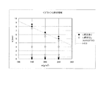
上記表1〜3のt1に関し、リチウム析出があったものを●、無かったものを○として図9にプロットした。この結果を一次関数フィッティングしたところ、片面の正極活物質質量をm(g/m2)としたとき、0.5≦t1≦12.3−0.03m(mm)の範囲内であることが好ましいことがわかった。 With respect to t1 in Tables 1 to 3, the case where lithium was precipitated was plotted in FIG. As a result of linear function fitting of this result, when the mass of the positive electrode active material on one side is m (g / m 2 ), it is within the range of 0.5 ≦ t1 ≦ 12.3-0.03 m (mm). It turned out to be preferable.
上記結果が得られたことについて以下に考察する。t1の値が0.5mm未満であると(X3,Y3,Z3)、巻きズレ等によって負極非対向正極領域405が生じた場合、図8に示すようにその間に介在されているセパレータ403に形成されている透過阻止領域431が過小である。このため吸蔵できる量以上のリチウムイオンが負極板の端部に移動して、負極板端部にリチウムが析出する。
また、t1の値が12.3−0.03mよりも大きいと(X4,X5,Y4,Z4,Z5)、図7に示すように負極非対向正極領域305の透過阻止領域331が過大であり、透過阻止領域331を迂回して移動したリチウムイオン304が負極板302端部まで移動する前に負極に吸蔵され(主に、透過阻止領域内周線3b近傍)、当該部分のリチウムイオン吸蔵量が過大となって、リチウムが析出する。
他方、t1の値が0.05以上且つ12.3−0.03m(mm)以下であると(A1〜A6,B1〜B7,C1〜C6)図3に示すようにセパレータ3の透過阻止領域31を迂回して負極板2の端部まで移動する量が適正に保たれ、安全性が向上するとともに、正極活物質層のサイズが従来の技術よりも大きくできるので、電池容量が増大する。したがって、0.5≦t1≦12.3−0.03mを満たすことが好ましい。
It will be discussed below that the above results were obtained. When the value of t1 is less than 0.5 mm (X3, Y3, Z3), when the negative electrode non-facing positive electrode region 405 is generated due to winding misalignment or the like, it is formed in the
If the value of t1 is larger than 12.3-0.03 m (X4, X5, Y4, Z4, Z5), the
On the other hand, when the value of t1 is 0.05 or more and 12.3-0.03 m (mm) or less (A1 to A6, B1 to B7, C1 to C6), as shown in FIG. The amount of movement to the end of the
また、t2が0.5mm以上であることが好ましいことがわかった。これは、t2が0.5mm未満であると(X2,Y2,Z2)、セパレータに形成されている透過阻止領域が過小であり、t1が0.5mm未満であるときと同様の現象が生じるためと考えられる。
なお、t2には特に上限を設ける必要はないが、セパレータのサイズが過大となると体積エネルギー密度が小さくなることに注意をする必要がある。
Moreover, it turned out that it is preferable that t2 is 0.5 mm or more. This is because when t2 is less than 0.5 mm (X2, Y2, Z2), the permeation blocking region formed in the separator is too small, and the same phenomenon as when t1 is less than 0.5 mm occurs. it is conceivable that.
It is not necessary to set an upper limit for t2, but it should be noted that the volume energy density decreases when the separator size is excessive.
また、上記表1〜3から、本発明電池A1〜A6,B1〜B7,C1〜C6は、従来の技術と同様に正負極ギャップ(正極板と負極板とのサイズの差)を設けた比較電池X1,Y1,Z1と比較し、電池容量が64〜83mAh大きくなっていることがわかる。このことは、正負極ギャップを設けていないので正極板のサイズが大きくなり、正極活物質量が増大したことによると考えられる。 In addition, from Tables 1 to 3, the present invention batteries A1 to A6, B1 to B7, and C1 to C6 are compared with the conventional technique in which a positive and negative electrode gap (a difference in size between the positive electrode plate and the negative electrode plate) is provided. It can be seen that the battery capacity is larger by 64 to 83 mAh than the batteries X1, Y1, and Z1. This is presumably because the positive and negative electrode gaps are not provided, so that the size of the positive electrode plate is increased and the amount of the positive electrode active material is increased.
〔その他の事項〕
尚、上記実施例では円筒型外装缶を使用したが、角型、ラミネート外装体等種々の形状にすることができることは当然のことである。
[Other matters]
In the above embodiment, a cylindrical outer can is used, but it is natural that various shapes such as a square shape and a laminate outer can be used.
また、正極活物質としては、リチウム含有遷移金属複合酸化物から選択される一種の化合物、あるいは二種以上の化合物を混合して用いることができ、例えば、コバルト酸リチウム、ニッケル酸リチウム、マンガン酸リチウム、鉄酸リチウム、またはこれらの酸化物に含まれる遷移金属の一部を他の元素で置換した酸化物等が用いることができる。 Further, as the positive electrode active material, one kind of compound selected from lithium-containing transition metal composite oxides, or a mixture of two or more kinds of compounds can be used. For example, lithium cobaltate, lithium nickelate, manganate Lithium, lithium ferrate, or an oxide obtained by substituting part of the transition metal contained in these oxides with another element can be used.
また、負極活物質としては、天然黒鉛、カーボンブラック、コークス、ガラス状炭素、炭素繊維、あるいはこれらの焼成体等の炭素質物を用いることができる。 Further, as the negative electrode active material, natural graphite, carbon black, coke, glassy carbon, carbon fiber, or a carbonaceous material such as a fired body thereof can be used.
また、電解質に使用する非水溶媒としては、カーボネート類、ラクトン類、エーテル類、ケトン類、ニトリル類、アミド類、スルホン系化合物、エステル類、芳香族炭化水素等から選択される化合物の一種、あるいは二種以上混合して用いることができる。これらの内でも、カーボネート類、ラクトン類、エーテル類、ケトン類、ニトリル類が好ましく、特にカーボネート類がさらに好ましい。これらの具体例としては、エチレンカーボネート、プロピレンカーボネート、ブチレンカーボネート、ジエチルカーボネート、ジメチルカーボネート、エチルメチルカーボネート、γ−ブチロラクトン、1,2−ジメトキシエタン、テトラヒドロフラン、アニソール、1,4−ジオキサン、4−メチル−2−ペンタノン、シクロヘキサノン、アセトニトリル、プロピオニトリル、ジメチルホルムアミド、スルホラン、蟻酸メチル、蟻酸エチル、酢酸メチル、酢酸エチル、酢酸プロピル、プロピオン酸エチルなどがあげられる。 In addition, as the non-aqueous solvent used for the electrolyte, a kind of compound selected from carbonates, lactones, ethers, ketones, nitriles, amides, sulfone compounds, esters, aromatic hydrocarbons, Or it can use in mixture of 2 or more types. Among these, carbonates, lactones, ethers, ketones, and nitriles are preferable, and carbonates are more preferable. Specific examples thereof include ethylene carbonate, propylene carbonate, butylene carbonate, diethyl carbonate, dimethyl carbonate, ethyl methyl carbonate, γ-butyrolactone, 1,2-dimethoxyethane, tetrahydrofuran, anisole, 1,4-dioxane, 4-methyl. -2-pentanone, cyclohexanone, acetonitrile, propionitrile, dimethylformamide, sulfolane, methyl formate, ethyl formate, methyl acetate, ethyl acetate, propyl acetate, ethyl propionate and the like.
また、電解質塩としては、LiN(C2F5SO2)2、LiN(CF3SO2)2、LiCF3SO3、LiPF6、LiBF4、LiAsF6、LiClO4等のリチウム塩から選択される化合物の一種単独で、あるいは二種以上混合して使用することができる。また、前記非水溶媒に対する電解質塩の溶解量は0.5〜2.0モル/リットルとすることが好ましい。 The electrolyte salt is selected from lithium salts such as LiN (C 2 F 5 SO 2 ) 2 , LiN (CF 3 SO 2 ) 2 , LiCF 3 SO 3 , LiPF 6 , LiBF 4 , LiAsF 6 and LiClO 4. These compounds can be used alone or in combination of two or more. The amount of electrolyte salt dissolved in the non-aqueous solvent is preferably 0.5 to 2.0 mol / liter.
上記の結果から明らかなように、本発明によると、安全性に優れ、且つ容量の大きい非水電解質二次電池を提供できるという優れた効果を奏する。よって、産業上の利用可能性は大きい。 As is apparent from the above results, according to the present invention, there is an excellent effect that a nonaqueous electrolyte secondary battery having excellent safety and large capacity can be provided. Therefore, industrial applicability is great.
1 正極板
2 負極板
3 セパレータ
31 透過阻止領域
4 リチウムイオン
5 負極非対向正極領域
DESCRIPTION OF
Claims (2)
非水電解質と、
を備える非水電解質二次電池において、
前記正極活物質層のサイズと前記負極活物質層のサイズとが実質的に同一であり、
前記セパレータのサイズが前記正極活物質層のサイズよりも大きく、
前記セパレータが前記微細孔を予め閉塞してなる透過阻止領域(31)を有し、
前記正極集電体の前記セパレータと直接対向する正極活物質層中の正極活物質質量をm(g/m2)とし、前記正極活物質層を覆うように前記セパレータと前記正極板とを重ね合わせたとき、前記正極活物質層の外周線(3a)と前記透過阻止領域(31)の内周線(3b)との直線距離t1が0.5≦t1≦12.3−0.03m(mm)を満たし、前記正極外周線(3a)と前記透過阻止領域(31)の外周線(3c)との直線距離t2が0.5≦t2(mm)を満たしている、
ことを特徴とする非水電解質二次電池。 A finely striped positive electrode plate having a positive electrode active material layer coated on a positive electrode current collector, a strip-like negative electrode plate having a negative electrode active material layer, and a fine electrode that is interposed between the positive and negative electrode plates and transmits lithium ions. An electrode body comprising a strip-shaped separator having holes;
A non-aqueous electrolyte,
In a non-aqueous electrolyte secondary battery comprising:
The size of the positive electrode active material layer and the size of the negative electrode active material layer are substantially the same,
The size of the separator is larger than the size of the positive electrode active material layer,
The separator has a permeation prevention region (31) formed by previously closing the micropores;
The positive electrode active material layer in the positive electrode active material layer directly facing the separator of the positive electrode current collector is defined as m (g / m 2 ), and the separator and the positive electrode plate are overlapped so as to cover the positive electrode active material layer. When combined, the linear distance t1 between the outer peripheral line (3a) of the positive electrode active material layer and the inner peripheral line (3b) of the permeation blocking region (31) is 0.5 ≦ t1 ≦ 12.3-0.03m ( mm), and a linear distance t2 between the positive electrode outer peripheral line (3a) and the outer peripheral line (3c) of the transmission blocking region (31) satisfies 0.5 ≦ t2 (mm).
A non-aqueous electrolyte secondary battery.
前記透過阻止領域(31)は、前記正負極間に介在させる前にセパレータを融点以上に加熱して、セパレータの微細孔を溶融させ閉塞することにより形成されたものである、
ことを特徴とする非水電解質二次電池。
The nonaqueous electrolyte secondary battery according to claim 1,
The permeation blocking region (31) is formed by heating the separator to a melting point or higher before being interposed between the positive and negative electrodes to melt and close the fine pores of the separator,
A non-aqueous electrolyte secondary battery.
Priority Applications (1)
| Application Number | Priority Date | Filing Date | Title |
|---|---|---|---|
| JP2003429647A JP2005190785A (en) | 2003-12-25 | 2003-12-25 | Non-aqueous electrolyte secondary battery |
Applications Claiming Priority (1)
| Application Number | Priority Date | Filing Date | Title |
|---|---|---|---|
| JP2003429647A JP2005190785A (en) | 2003-12-25 | 2003-12-25 | Non-aqueous electrolyte secondary battery |
Publications (2)
| Publication Number | Publication Date |
|---|---|
| JP2005190785A true JP2005190785A (en) | 2005-07-14 |
| JP2005190785A5 JP2005190785A5 (en) | 2006-12-21 |
Family
ID=34788241
Family Applications (1)
| Application Number | Title | Priority Date | Filing Date |
|---|---|---|---|
| JP2003429647A Pending JP2005190785A (en) | 2003-12-25 | 2003-12-25 | Non-aqueous electrolyte secondary battery |
Country Status (1)
| Country | Link |
|---|---|
| JP (1) | JP2005190785A (en) |
Cited By (10)
| Publication number | Priority date | Publication date | Assignee | Title |
|---|---|---|---|---|
| JP2007250319A (en) * | 2006-03-15 | 2007-09-27 | Nec Tokin Corp | Stacked battery |
| JP2008140551A (en) * | 2006-11-29 | 2008-06-19 | Nissan Motor Co Ltd | Nonaqueous electrolyte secondary battery |
| JP2012204334A (en) * | 2011-03-28 | 2012-10-22 | Mitsubishi Heavy Ind Ltd | Nonaqueous electrolyte secondary battery, and method for manufacturing nonaqueous electrolyte secondary battery |
| JP2012216460A (en) * | 2011-04-01 | 2012-11-08 | Gs Yuasa Corp | Nonaqueous electrolyte secondary battery |
| WO2013069134A1 (en) * | 2011-11-10 | 2013-05-16 | トヨタ自動車株式会社 | Battery |
| JP2013161684A (en) * | 2012-02-06 | 2013-08-19 | Toyota Industries Corp | Power storage device, vehicle and method of manufacturing electrode body |
| US8879700B2 (en) | 2005-10-12 | 2014-11-04 | Panasonic Corporation | Communication apparatus, integrated circuit, and communication method |
| EP3073549A1 (en) * | 2015-03-25 | 2016-09-28 | Automotive Energy Supply Corporation | Lithium ion secondary battery and method for manufacturing the same |
| DE112011105588B4 (en) * | 2011-09-01 | 2021-01-07 | Toyota Jidosha Kabushiki Kaisha | Secondary battery with non-aqueous electrolyte |
| WO2021153528A1 (en) | 2020-01-31 | 2021-08-05 | パナソニックIpマネジメント株式会社 | Non-aqueous electrolyte secondary battery |
-
2003
- 2003-12-25 JP JP2003429647A patent/JP2005190785A/en active Pending
Cited By (14)
| Publication number | Priority date | Publication date | Assignee | Title |
|---|---|---|---|---|
| US8879700B2 (en) | 2005-10-12 | 2014-11-04 | Panasonic Corporation | Communication apparatus, integrated circuit, and communication method |
| US9419756B2 (en) | 2005-10-12 | 2016-08-16 | Panasonic Corporation | Communication apparatus, integrated circuit, and communication method |
| JP2007250319A (en) * | 2006-03-15 | 2007-09-27 | Nec Tokin Corp | Stacked battery |
| JP2008140551A (en) * | 2006-11-29 | 2008-06-19 | Nissan Motor Co Ltd | Nonaqueous electrolyte secondary battery |
| JP2012204334A (en) * | 2011-03-28 | 2012-10-22 | Mitsubishi Heavy Ind Ltd | Nonaqueous electrolyte secondary battery, and method for manufacturing nonaqueous electrolyte secondary battery |
| JP2012216460A (en) * | 2011-04-01 | 2012-11-08 | Gs Yuasa Corp | Nonaqueous electrolyte secondary battery |
| DE112011105588B4 (en) * | 2011-09-01 | 2021-01-07 | Toyota Jidosha Kabushiki Kaisha | Secondary battery with non-aqueous electrolyte |
| CN103918103A (en) * | 2011-11-10 | 2014-07-09 | 丰田自动车株式会社 | Battery |
| JPWO2013069134A1 (en) * | 2011-11-10 | 2015-04-02 | トヨタ自動車株式会社 | battery |
| WO2013069134A1 (en) * | 2011-11-10 | 2013-05-16 | トヨタ自動車株式会社 | Battery |
| US9698397B2 (en) | 2011-11-10 | 2017-07-04 | Toyota Jidosha Kabushiki Kaisha | Battery |
| JP2013161684A (en) * | 2012-02-06 | 2013-08-19 | Toyota Industries Corp | Power storage device, vehicle and method of manufacturing electrode body |
| EP3073549A1 (en) * | 2015-03-25 | 2016-09-28 | Automotive Energy Supply Corporation | Lithium ion secondary battery and method for manufacturing the same |
| WO2021153528A1 (en) | 2020-01-31 | 2021-08-05 | パナソニックIpマネジメント株式会社 | Non-aqueous electrolyte secondary battery |
Similar Documents
| Publication | Publication Date | Title |
|---|---|---|
| JP5156406B2 (en) | Positive electrode for lithium secondary battery, method for producing the same, and lithium secondary battery | |
| JP6531652B2 (en) | Negative electrode for non-aqueous electrolyte secondary battery | |
| WO2012128160A1 (en) | Positive electrode plate for anhydrous electrolyte secondary cell, method for manufacturing positive electrode plate, and anhydrous electrolyte secondary cell and method for manufacturing same | |
| WO2010131401A1 (en) | Electrode for lithium ion secondary battery, and lithium ion secondary battery | |
| WO2011155060A1 (en) | Lithium secondary battery and production method for same | |
| WO2018116876A1 (en) | Cylindrical non-aqueous electrolyte secondary battery | |
| JP2007172880A (en) | Battery and its manufacturing method | |
| JP4097443B2 (en) | Lithium secondary battery | |
| JP2008262826A (en) | Coin-shaped nonaqueous electrolytic solution secondary battery | |
| JP2007005158A (en) | Lithium ion secondary battery | |
| US9567238B2 (en) | Negative electrode active material for lithium ion secondary battery, negative electrode for lithium ion secondary battery, and lithium ion secondary battery | |
| US20080113260A1 (en) | Prismatic nonaqueous electrolyte secondary battery and method for manufacturing the same | |
| JP2005190785A (en) | Non-aqueous electrolyte secondary battery | |
| JP6897228B2 (en) | Active material, electrodes and lithium-ion secondary battery | |
| JP2008218177A (en) | Manufacturing method of positive active material and nonaqueous electrolyte secondary battery using the positive active material | |
| WO2013038702A1 (en) | Nonaqueous electrolyte secondary cell | |
| JP3332781B2 (en) | Lithium ion battery | |
| JP6962231B2 (en) | Non-aqueous electrolyte secondary battery | |
| JP2008243704A (en) | Cylindrical type nonaqueous electrolyte battery | |
| JP4404612B2 (en) | Nonaqueous electrolyte secondary battery | |
| JP2007227292A (en) | Cylindrical battery and method for manufacturing same | |
| JP2007172879A (en) | Battery and its manufacturing method | |
| JP4954468B2 (en) | Winding electrode, manufacturing method thereof, and battery manufacturing method | |
| JP4420666B2 (en) | Nonaqueous electrolyte secondary battery | |
| JP2007172878A (en) | Battery and its manufacturing method |
Legal Events
| Date | Code | Title | Description |
|---|---|---|---|
| A521 | Written amendment |
Free format text: JAPANESE INTERMEDIATE CODE: A523 Effective date: 20061101 |
|
| A621 | Written request for application examination |
Free format text: JAPANESE INTERMEDIATE CODE: A621 Effective date: 20061101 |
|
| A977 | Report on retrieval |
Free format text: JAPANESE INTERMEDIATE CODE: A971007 Effective date: 20090715 |
|
| A131 | Notification of reasons for refusal |
Free format text: JAPANESE INTERMEDIATE CODE: A131 Effective date: 20090721 |
|
| A02 | Decision of refusal |
Free format text: JAPANESE INTERMEDIATE CODE: A02 Effective date: 20091208 |