JP2005189542A - Display system, display program and display method - Google Patents
Display system, display program and display method Download PDFInfo
- Publication number
- JP2005189542A JP2005189542A JP2003431384A JP2003431384A JP2005189542A JP 2005189542 A JP2005189542 A JP 2005189542A JP 2003431384 A JP2003431384 A JP 2003431384A JP 2003431384 A JP2003431384 A JP 2003431384A JP 2005189542 A JP2005189542 A JP 2005189542A
- Authority
- JP
- Japan
- Prior art keywords
- color image
- image data
- display
- test
- data
- Prior art date
- Legal status (The legal status is an assumption and is not a legal conclusion. Google has not performed a legal analysis and makes no representation as to the accuracy of the status listed.)
- Pending
Links
Images


Classifications
-
- H—ELECTRICITY
- H04—ELECTRIC COMMUNICATION TECHNIQUE
- H04N—PICTORIAL COMMUNICATION, e.g. TELEVISION
- H04N5/00—Details of television systems
- H04N5/14—Picture signal circuitry for video frequency region
- H04N5/21—Circuitry for suppressing or minimising disturbance, e.g. moiré or halo
-
- G—PHYSICS
- G09—EDUCATION; CRYPTOGRAPHY; DISPLAY; ADVERTISING; SEALS
- G09G—ARRANGEMENTS OR CIRCUITS FOR CONTROL OF INDICATING DEVICES USING STATIC MEANS TO PRESENT VARIABLE INFORMATION
- G09G5/00—Control arrangements or circuits for visual indicators common to cathode-ray tube indicators and other visual indicators
- G09G5/02—Control arrangements or circuits for visual indicators common to cathode-ray tube indicators and other visual indicators characterised by the way in which colour is displayed
-
- H—ELECTRICITY
- H04—ELECTRIC COMMUNICATION TECHNIQUE
- H04N—PICTORIAL COMMUNICATION, e.g. TELEVISION
- H04N9/00—Details of colour television systems
- H04N9/12—Picture reproducers
- H04N9/31—Projection devices for colour picture display, e.g. using electronic spatial light modulators [ESLM]
- H04N9/3191—Testing thereof
- H04N9/3194—Testing thereof including sensor feedback
-
- H—ELECTRICITY
- H04—ELECTRIC COMMUNICATION TECHNIQUE
- H04N—PICTORIAL COMMUNICATION, e.g. TELEVISION
- H04N9/00—Details of colour television systems
- H04N9/64—Circuits for processing colour signals
- H04N9/646—Circuits for processing colour signals for image enhancement, e.g. vertical detail restoration, cross-colour elimination, contour correction, chrominance trapping filters
-
- G—PHYSICS
- G09—EDUCATION; CRYPTOGRAPHY; DISPLAY; ADVERTISING; SEALS
- G09G—ARRANGEMENTS OR CIRCUITS FOR CONTROL OF INDICATING DEVICES USING STATIC MEANS TO PRESENT VARIABLE INFORMATION
- G09G2320/00—Control of display operating conditions
- G09G2320/06—Adjustment of display parameters
- G09G2320/0666—Adjustment of display parameters for control of colour parameters, e.g. colour temperature
-
- G—PHYSICS
- G09—EDUCATION; CRYPTOGRAPHY; DISPLAY; ADVERTISING; SEALS
- G09G—ARRANGEMENTS OR CIRCUITS FOR CONTROL OF INDICATING DEVICES USING STATIC MEANS TO PRESENT VARIABLE INFORMATION
- G09G2360/00—Aspects of the architecture of display systems
- G09G2360/14—Detecting light within display terminals, e.g. using a single or a plurality of photosensors
- G09G2360/145—Detecting light within display terminals, e.g. using a single or a plurality of photosensors the light originating from the display screen
Landscapes
- Engineering & Computer Science (AREA)
- Multimedia (AREA)
- Signal Processing (AREA)
- Physics & Mathematics (AREA)
- Computer Hardware Design (AREA)
- General Physics & Mathematics (AREA)
- Theoretical Computer Science (AREA)
- Controls And Circuits For Display Device (AREA)
- Video Image Reproduction Devices For Color Tv Systems (AREA)
- Processing Of Color Television Signals (AREA)
- Liquid Crystal Display Device Control (AREA)
- Control Of Indicators Other Than Cathode Ray Tubes (AREA)
Abstract
Description
本発明は、光学的フレアの影響を補正して画像の表示を行う表示システム、表示プログラム、表示方法に関する。 The present invention relates to a display system, a display program, and a display method for displaying an image by correcting the influence of optical flare.
近年、電子商取引や電子美術館・博物館などの実現を目的として、被写体の画像をディスプレイ上に正確な色で再現する技術の研究が活発に行われている。 In recent years, for the purpose of realizing electronic commerce, electronic art museums, museums, and the like, research on techniques for reproducing an object image with an accurate color on a display has been actively conducted.
これらの研究は、画像入力装置や画像表示装置の色特性を測定して、これらの装置の色特性情報に基づいて色信号の補正を行うものとなっている。ここで用いられる装置の色特性情報のフォーマットを標準化することは、色再現システムを普及させる上で重要であり、International Color Consortium(ICC)では装置の色特性情報をデバイスプロファイルとして規定している(http://www.color.org)。 These studies measure the color characteristics of image input devices and image display devices, and correct color signals based on the color property information of these devices. Standardizing the format of the color characteristic information of the apparatus used here is important in spreading the color reproduction system. The International Color Consortium (ICC) defines the color characteristic information of the apparatus as a device profile ( http://www.color.org).
上述したようなICCのデバイスプロファイルや現行のカラー画像システムでは、カラー画像機器または画像データに対して、画像の空間座標には依存しない情報として色特性を規定し、この色特性情報に基づいて色再現を行っている。 In the ICC device profile and the current color image system as described above, color characteristics are defined for color image equipment or image data as information that does not depend on the spatial coordinates of the image, and the color characteristics are determined based on the color characteristic information. It is being reproduced.
上述したようなICCのデバイスプロファイルや現行のカラー画像システムでは、表示装置における光学的なフレアのような、画像内のある位置の色が他の位置の色に及ぼす影響についてまでを考慮することができるものとはなっていない。そのために、光学的なフレアの影響が生じるような表示装置では、十分に正確な色再現を行うことができない場合があった。 In the ICC device profile as described above and the current color image system, the influence of the color at one position in the image on the color at the other position, such as optical flare in the display device, is considered. It is not possible. For this reason, in a display device in which the influence of optical flare occurs, there are cases where sufficiently accurate color reproduction cannot be performed.
本発明は上記事情に鑑みてなされたものであり、光学的フレアの影響を低減して意図した通りの色再現を行い得る表示システム、表示プログラム、表示方法を提供することを目的としている。 The present invention has been made in view of the above circumstances, and an object thereof is to provide a display system, a display program, and a display method capable of reducing the influence of optical flare and performing color reproduction as intended.
上記の目的を達成するために、第1の発明による表示システムは、カラー画像を表示するためのカラー画像表示装置と、カラー画像データを補正することにより上記カラー画像表示装置へ出力するための補正カラー画像データを生成する画像補正装置と、を具備し、上記画像補正装置は、上記カラー画像表示装置へ出力する複数のテストカラー画像データと、これら複数のテストカラー画像データに各対応して該カラー画像表示装置に表示されるテストカラー画像の表示色の空間分布と、の関係に基づいて、上記カラー画像データから、上記カラー画像表示装置の光学的フレアを補正する補正カラー画像データを算出するものである。 To achieve the above object, a display system according to a first invention includes a color image display device for displaying a color image, and a correction for outputting the color image data to the color image display device by correcting the color image data. An image correction device for generating color image data, the image correction device corresponding to each of the plurality of test color image data to be output to the color image display device and the plurality of test color image data. Based on the relationship with the spatial distribution of the display color of the test color image displayed on the color image display device, corrected color image data for correcting the optical flare of the color image display device is calculated from the color image data. Is.
また、第2の発明による表示システムは、上記第1の発明による表示システムにおいて、上記画像補正装置が、上記テストカラー画像データに対応して上記カラー画像表示装置に表示されるテストカラー画像の表示色の空間分布を測定するためのテストカラー画像測定手段を有して構成されたものである。 A display system according to a second invention is the display system according to the first invention, wherein the image correction device displays a test color image displayed on the color image display device corresponding to the test color image data. The test color image measuring means for measuring the color spatial distribution is provided.
さらに、第3の発明による表示システムは、上記第2の発明による表示システムにおいて、上記テストカラー画像測定手段が、輝度計、色彩計、分光放射輝度計、モノクロカメラ、カラーカメラ、マルチバンドカメラ、の内の少なくとも1つを含むものである。 Furthermore, the display system according to a third invention is the display system according to the second invention, wherein the test color image measuring means includes a luminance meter, a color meter, a spectral radiance meter, a monochrome camera, a color camera, a multiband camera, Including at least one of the following.
第4の発明による表示システムは、上記第1から第3の発明による表示システムにおいて、上記画像補正装置が、上記テストカラー画像データと、該テストカラー画像データに対応して上記カラー画像表示装置に表示されるテストカラー画像の表示色の空間分布と、に基づいて該カラー画像表示装置の表示特性データを算出する表示特性算出手段を有して構成され、上記表示特性算出手段により算出した表示特性データに基づいて、上記補正カラー画像データを算出するものである。 A display system according to a fourth invention is the display system according to any of the first to third inventions, wherein the image correction device is connected to the test color image data and the color image display device corresponding to the test color image data. Display characteristics calculated by display characteristic calculation means for calculating display characteristic data of the color image display device based on the spatial distribution of the display color of the displayed test color image, and calculated by the display characteristic calculation means The corrected color image data is calculated based on the data.
第5の発明による表示システムは、上記第4の発明による表示システムにおいて、上記画像補正装置が、上記表示特性データに基づいて上記カラー画像データに係るフレア分布データを算出し、該カラー画像データからこのフレア分布データを減算することにより、上記補正カラー画像データを算出するフレア算出手段をさらに有して構成されたものである。 A display system according to a fifth invention is the display system according to the fourth invention, wherein the image correction device calculates flare distribution data relating to the color image data based on the display characteristic data, and from the color image data. The apparatus further includes flare calculation means for calculating the corrected color image data by subtracting the flare distribution data.
第6の発明による表示システムは、上記第5の発明による表示システムにおいて、複数画素でなるカラー画像データの各画素データを成分とするベクトルをP、このベクトルPの成分数をN(Nは自然数)、N×Nの単位行列をE、上記カラー画像表示装置の表示特性のN×Nの行列による表現をM、任意の定数をK、とすると、上記フレア分布データを表すベクトルFは、次の数式、

第7の発明による表示プログラムは、コンピュータに、カラー画像表示装置へ複数のテストカラー画像データを出力して複数のテストカラー画像を表示させる第1の手順、上記第1の手順により上記カラー画像表示装置に表示された複数のテストカラー画像の表示色の空間分布をそれぞれ取得する第2の手順、上記複数のテストカラー画像データとこれら複数のテストカラー画像データに各対応して上記第2の手順により取得したテストカラー画像の表示色の空間分布とに基づいてカラー画像データから上記カラー画像表示装置の光学的フレアを補正する補正カラー画像データを算出する第3の手順、上記第3の手順により算出された補正カラー画像データを上記カラー画像表示装置へ出力して表示させる第4の手順、を実行させるためのプログラムである。 A display program according to a seventh aspect of the present invention is a first procedure for causing a computer to output a plurality of test color image data to a color image display device to display a plurality of test color images, and to display the color image according to the first procedure. A second procedure for acquiring the spatial distribution of display colors of a plurality of test color images displayed on the apparatus, and the second procedure corresponding to each of the plurality of test color image data and the plurality of test color image data. A third procedure for calculating corrected color image data for correcting optical flare of the color image display device from the color image data based on the spatial distribution of the display color of the test color image obtained by the above, and the third procedure A process for executing the fourth procedure for outputting the calculated corrected color image data to the color image display device for display. A gram.
第8の発明による表示方法は、カラー画像表示装置へ複数のテストカラー画像データを出力して複数のテストカラー画像を表示させる第1の手順と、上記第1の手順により上記カラー画像表示装置に表示された複数のテストカラー画像の表示色の空間分布をそれぞれ取得する第2の手順と、上記複数のテストカラー画像データとこれら複数のテストカラー画像データに各対応して上記第2の手順により取得したテストカラー画像の表示色の空間分布とに基づいてカラー画像データから上記カラー画像表示装置の光学的フレアを補正する補正カラー画像データを算出する第3の手順と、上記第3の手順により算出された補正カラー画像データを上記カラー画像表示装置へ出力して表示させる第4の手順と、を含む方法である。 A display method according to an eighth aspect of the present invention is a first procedure for outputting a plurality of test color image data to a color image display device to display a plurality of test color images, and the color image display device according to the first procedure. A second procedure for acquiring the spatial distribution of display colors of the plurality of displayed test color images, and the second procedure for each of the plurality of test color image data and the plurality of test color image data. A third procedure for calculating corrected color image data for correcting the optical flare of the color image display device from the color image data based on the acquired spatial distribution of the display color of the test color image, and the third procedure. And a fourth procedure for outputting the calculated corrected color image data to the color image display device for display.
本発明の表示システム、表示プログラム、表示方法によれば、光学的フレアの影響を低減して意図した通りの色再現を行うことが可能となる。 According to the display system, display program, and display method of the present invention, it is possible to reduce the influence of optical flare and perform color reproduction as intended.
まず、実施例を具体的に説明する前に、本発明に用いられる原理について詳細に説明する。この原理は、入力画像データが、表示装置の光学的フレア(以下では適宜、単にフレアと述べる。)などの影響を受けて異なる表示画像データとなる場合において、どのような補正入力画像データを入力すれば本来の入力画像データと同一の表示画像データが得られるかを求めるものである。 First, the principle used in the present invention will be described in detail before specifically describing the embodiments. This principle is based on what kind of corrected input image data is input when the input image data becomes different display image data due to the influence of optical flare of the display device (hereinafter simply referred to as flare as appropriate). Then, it is determined whether or not the same display image data as the original input image data can be obtained.
[原理]
表示装置へ入力される画素数Nの入力画像データを(p1,p2,…,pN)tとする。ここに、右肩の添え字tは転置を表している。また、この入力画像データに対して、実際に表示される画像の光分布を画素数Nの画像データとして離散化して表した表示画像データを(g1,g2,…,gN)tとする。なお、この表示画像データは、例えば、デジタルカメラにより表示装置に表示されている画像を撮影することにより、取得することができる。この表示画像データは、表示装置のフレア等の影響を受けるために、一般には入力画像データと一致せず、他の画素位置の信号により表示される光の一部が重畳されたものとなる。さらに、表示装置への入力画像信号が0である場合にも、表示画像データは一般には0にはならない。このときの表示画像データをバイアス(o1,o2,…,oN)tとする。これらの影響を考慮して、入力画像データと表示画像データとの関係をモデル化したものが数式1である。
[数1]
Assume that the input image data of N pixels input to the display device is (p 1 , p 2 ,..., P N ) t . Here, the subscript t on the right shoulder represents transposition. Further, display image data obtained by discretizing the light distribution of an actually displayed image as image data of the number of pixels N with respect to this input image data is represented by (g 1 , g 2 ,..., G N ) t . To do. The display image data can be acquired by, for example, taking an image displayed on the display device with a digital camera. Since this display image data is affected by flare and the like of the display device, in general, it does not coincide with the input image data, and a part of light displayed by signals at other pixel positions is superimposed. Further, even when the input image signal to the display device is 0, the display image data is generally not 0. The display image data at this time is defined as bias (o 1 , o 2 ,..., O N ) t . In consideration of these influences, Formula 1 is a model of the relationship between the input image data and the display image data.
[Equation 1]
この数式1の行列式における各要素の文字に対応する大文字を用いて、該数式1を簡単に表記したものが次の数式2である。
[数2]
![]()
[Equation 2]
![]()
上記数式1あるいは数式2は、ある画素位置n(n=1〜N)の表示光が、該画素位置nの周囲の他の画素位置に広がって、該他の画素位置の表示光に加算される現象を、全ての画素位置nについてモデル化したものである。ここで、数式2に示したような行列M(数式1においては、要素mij(i=1〜N,j=1〜N)でなる行列)を、表示装置の表示特性と呼ぶ。
In the
上記表示画像データGは、本来は、上記入力画像データPと一致することが望ましいが、上述したように、表示画像はフレア等の影響を受けるために、一般には、入力画像データと表示画像データとは異なる。 Originally, the display image data G desirably matches the input image data P. However, as described above, since the display image is affected by flare or the like, the input image data and the display image data are generally used. Is different.
そこで、入力画像データを補正し、補正した入力画像データを用いて取得した表示画像データが、本来の入力画像データと一致するか、もしくは近似するように、該補正した入力画像データを算出することを考える。この補正入力画像データをP’とすると、該補正入力画像データP’に対応する表示画像データである補正表示画像データG’は、次の数式3に示すようになる。
[数3]
![]()
[Equation 3]
![]()
この数式3に示した補正表示画像データG’が、本来の入力画像データPと一致する条件式は、次の数式4に示すようになる。
[数4]
![]()
[Equation 4]
![]()
この数式4を満たすためには、上記数式3を用いることにより、次の数式5に示すような補正入力画像データP’を用いれば良い。
[数5]
![]()
[Equation 5]
![]()
この数式5に示すような表示特性Mは、上述したようにN×Nの行列であり、例えば1280×1024の画素でなる表示装置の場合には、N=1280×1024=1310720となるために、一般にデータサイズは非常に大きくなるといえる。
As described above, the display characteristic M shown in
これに対して、表示特性Mが特別な特性をもつ場合には、演算をより簡単に行うことができる可能性がある。例えば、表示装置におけるフレア等による光の広がり方が、画素位置にほぼ依存せず、同じ分布で近似することができる場合を考える。このときの表示特性をM’(m’1,m’2,…,m’N)とすると、上記数式1または数式2は、この表示特性M’と入力画像データPとのコンボリューションを用いて、次の数式6に示すように表される。
[数6]
![]()
[Equation 6]
![]()
この数式6における入力画像データPを補正入力画像データP’とし、さらに上記数式4に示した条件を用いることにより、次の数式7が得られる。
[数7]
![]()
[Equation 7]
![]()
表示特性M’が既知である場合には、この数式7から補正入力画像データP’を算出することが可能である。すなわち、2つの画像のコンボリューション画像(ここではP−O)から、一方の画像(ここではM’)が既知である場合に、他方の画像(ここではP’)を算出するデコンボリューションに関する技術は公知である。例えば、文献1(Rosenfeld and A. C. Kak, Digital Picture Processing, Academic Press 1976(長尾 真 監訳 ディジタル画像処理 近代科学社 1978))の第7章に記載されているような手法を用いることができる。 When the display characteristic M ′ is known, the corrected input image data P ′ can be calculated from the equation (7). In other words, when one image (here, M ′) is known from the convolution image (here, PO) of the two images, a technique related to deconvolution that calculates the other image (here, P ′). Is known. For example, a technique as described in Chapter 7 of Reference 1 (Rosenfeld and A. C. Kak, Digital Picture Processing, Academic Press 1976 (translated by Makoto Nagao, Digital Image Processing Modern Science Co., 1978)) can be used.
上記数式5に示したような補正方法は、要素数の多い行列Mの逆行列の演算が含まれ、また、上記数式7や文献1に記載されたような補正方法は、コンボリューションの逆演算などが含まれるために、演算が複雑であり、処理系の負荷が大きくなったり処理時間を要したりすることが考えられる。
The correction method as shown in
これに対して、より簡便な補正方法として、フレア量を入力画像データから差し引くことで補正入力画像データを算出することを考える。今、表示画像データGが、数式8に示すような入力画像データPとバイアスOとフレア等の影響により生じるフレア分布データであるフレア成分Fとの和により表されるものとしてモデル化する。
[数8]
[Equation 8]
この数式8におけるフレア成分Fは、さらに数式2を用いることにより、次の数式9に示すように表される。
[数9]
[Equation 9]
この数式9で与えられるFを用いて、P−F−M-1Oを補正入力画像データP’として入力した場合に、補正表示画像データG’は、数式3から、
[数10]
[Equation 10]
ここで、Mの非対角成分が1よりも小さい場合、補正表示画像データG’のフレア補正誤差である数式10の第2項の−(M−E)2Pは、補正前の表示画像データGのフレアによる影響である数式9の(M−E)Pよりも小さい値となり、フレアの影響が改善されることが分かる。
Here, when the non-diagonal component of M is smaller than 1, the second term − (ME) 2 P of
さらにこの結果を考慮して、次の数式11により与えられるF
[数11]
![]()
[数12]
![]()
[Equation 11]
![]()
[Equation 12]
![]()
この数式12の第2項の(M−E)3Pは、フレア補正誤差であり、次数が3次となっていて、より一層フレアの影響が小さくなっていることが分かる。
The second term (ME) 3 P in
これを、同様にしてK次の項まで行った場合のフレアFは、次の数式13に示すように与えられる。
[数13]
[Equation 13]
従って、この数式13に示すようなフレアFを補正するための補正入力画像データP’は、次の数式14に示すようになる。
[数14]
[Formula 14]
この数式14におけるKを大きな値にするほど、フレアの影響をより小さく抑制する補正を行うことができる。あるいは、計算量や計算時間などを考慮してKを適宜の値とすることにより、処理系の負荷を抑制しながらフレアを良好に取り除く補正を行うことができる。 As K in Equation 14 is increased, correction that suppresses the influence of flare can be performed. Alternatively, by setting K to an appropriate value in consideration of the calculation amount, calculation time, etc., it is possible to correct the flare well while suppressing the load on the processing system.
このような方法によるフレア補正に対しても、フレア等による光の広がり方が画素位置に依存することなく同じ分布であると近似できる場合には、数式9のFはコンボリューションを用いて、次の数式15に示すように置き換えることができる。
[数15]
[Equation 15]
同様に数式13は、
[数16]
![]()
[Equation 16]
![]()
従って、数式14に対応する補正入力画像データP’は、次の数式17に示すようになる。
[数17]
[Equation 17]
ここまでの説明は、画像データを1チャンネルのデータとして扱ったものであったが、画像がカラー画像である場合は、画像データは一般に3チャンネルのデータとして扱われる。従って、この場合には、RGB各チャンネル毎に上述したような表示特性Mまたは表示特性M’を算出して、算出された表示特性に基づきフレア補正を行うことになる。 The description so far has dealt with image data as one-channel data. However, when an image is a color image, the image data is generally handled as three-channel data. Accordingly, in this case, the display characteristic M or the display characteristic M ′ as described above is calculated for each RGB channel, and flare correction is performed based on the calculated display characteristic.
さらに、カラー画像が4原色以上の原色数の画像データとして表される場合にも、同様に、各チャンネルの画像に対して上述したようなフレア補正処理を行うことにより、カラー画像として本来意図した表示を達成することが可能となる。 Further, when a color image is represented as image data having the number of primary colors of four or more primary colors, the color image is originally intended by performing the flare correction processing as described above on the image of each channel. It is possible to achieve the display.
また、表示装置やデジタルカメラ等のカラー画像機器の信号値は、対応する輝度と非線形な関係にある場合がある。このような場合には、各信号の非線形性を補正してから上述したような処理を行う必要があるが、こうした階調特性の補正は公知の技術であるために、ここでは説明を省略している。すなわち、上述した説明は、信号の非線形性を補正した後の、リニアな空間における原理を説明したものとなっている。 In addition, the signal value of a color image device such as a display device or a digital camera may have a non-linear relationship with the corresponding luminance. In such a case, it is necessary to perform the above-described processing after correcting the nonlinearity of each signal. However, since the correction of such gradation characteristics is a known technique, description thereof is omitted here. ing. That is, the above description explains the principle in the linear space after correcting the nonlinearity of the signal.
以下、図面を参照して本発明の実施例を説明する。 Embodiments of the present invention will be described below with reference to the drawings.
図1から図10は本発明の実施例1を示したものであり、図1は表示システムの構成の概要を示す図である。 1 to 10 show a first embodiment of the present invention, and FIG. 1 is a diagram showing an outline of a configuration of a display system.
この表示システムは、画像を投影するためのカラー画像表示装置たるプロジェクタ1と、このプロジェクタ1により投影される補正画像を生成するための画像補正装置2と、上記プロジェクタ1から画像が投影されるカラー画像表示装置たるスクリーン3と、このスクリーン3に表示される画像の全領域を撮影し得るように配置された例えばデジタルカメラ等でなるテストカラー画像測定手段でありカラーカメラたるテスト画像撮影カメラ4と、を有して構成されている。
This display system includes a
上記テスト画像撮影カメラ4は、広い意味での画像補正装置に含まれるものであり、撮影レンズの光学的特性に起因する画像の面内ムラや、あるいは撮像素子の面内感度ムラに起因する画像の面内ムラなどを補正することができる回路等を備えていて、出力する例えばRGBのデジタル画像データは、これらの補正が行われたものであるとする。さらに、このテスト画像撮影カメラ4は、入力光強度に対して線形な応答で信号を出力するものとする。
The test
次に、このような表示システムの動作について説明する。 Next, the operation of such a display system will be described.
まず、表示システムにおいて、光学的フレアを補正するのに必要な表示特性データを取得するときの動作は、以下のようになっている。 First, in the display system, an operation when acquiring display characteristic data necessary for correcting optical flare is as follows.
画像補正装置2は、予め内部に記憶している所定のテストカラー画像データをプロジェクタ1へ出力する。
The
プロジェクタ1は、該画像補正装置2から供給されたテストカラー画像データを、スクリーン3に投影する。
The
画像補正装置2は、このスクリーン3に表示されている上記テストカラー画像データに対応した表示色分布の画像を、テスト画像撮影カメラ4を制御することにより撮影させて転送させ、取り込む。
The
そして、該画像補正装置2は、テスト画像撮影カメラ4から取得したカラー画像データと、上記プロジェクタ1へ供給した元のテストカラー画像データと、を用いて、カラー画像データを補正するために用いる表示特性データを算出する。
The
次に、表示特性データ取得後の表示システムにより、通常の画像を投影するときの動作は、以下のようになっている。なお、この通常の画像を投影するときには、上記テスト画像撮影カメラ4は不要であるために、例えば取り外されている。
Next, the operation when a normal image is projected by the display system after obtaining the display characteristic data is as follows. Note that when projecting this normal image, the test
また、画像補正装置2の内部には、輝度に対して線形となるように変換されたカラー画像データが、予め記憶されているものとする。
In addition, it is assumed that color image data converted so as to be linear with respect to luminance is stored in advance in the
画像補正装置2は、予め内部に記憶しているカラー画像データを、上述したように算出した表示特性データを用いて補正してから、補正カラー画像データとして内部に記憶しておく。
The
その後に、操作者により表示するカラー画像データが選択されたときに、該選択に対応する補正カラー画像データをプロジェクタ1へ出力する。
Thereafter, when color image data to be displayed is selected by the operator, corrected color image data corresponding to the selection is output to the
プロジェクタ1は、画像補正装置2から供給された補正カラー画像データに基づいて、スクリーン3へ画像を投影して表示する。
The
これにより、スクリーン3には、フレア等の影響を補正し得るような画像が表示され、観察者は、画像の表示者が本来意図した画像を観察することが可能となる。
Thereby, an image that can correct the influence of flare or the like is displayed on the
なお、本実施例では、プロジェクタ1へ入力される画像データと、テスト画像撮影カメラ4から出力される画像データと、画像補正装置2で処理される画像データとは、全て、横1280画素×縦1024画素で、かつ各画素がRGBの3色でなる、3チャンネルの画像データであるとする。
In this embodiment, the image data input to the
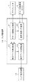
次に、図2は、画像補正装置2の構成を示すブロック図である。
Next, FIG. 2 is a block diagram showing a configuration of the
この画像補正装置2は、予め記憶している所定のテストカラー画像データを上記プロジェクタ1へ出力して上記テスト画像撮影カメラ4から該テストカラー画像データに係る撮影されたカラー画像データ(撮影画像データ)を取得し、取得した撮影画像データと元のテストカラー画像データとに基づいて表示特性データを算出するフレア算出装置13と、表示用のカラー画像データを記憶するものであってこのカラー画像データを後述するフレア補正装置12により補正して得られる補正カラー画像データも記憶する画像データ記憶装置11と、この画像データ記憶装置11からカラー画像データを取得して上記フレア算出装置13により算出された表示特性データを用いて補正し、補正後のカラー画像データ(補正カラー画像データ)を該画像データ記憶装置11へ再び出力して記憶させるフレア補正装置12と、を有して構成されている。
The
次に、このような画像補正装置2の動作について説明する。
Next, the operation of such an
まず、表示特性データを取得するときには、以下のように動作する。 First, when obtaining display characteristic data, the following operation is performed.
上記フレア算出装置13は、上記テストカラー画像データを上記プロジェクタ1へ出力して、テストカラー画像をスクリーン3上に表示させる。フレア算出装置13は、これと同期して、テスト画像撮影カメラ4を制御することにより、スクリーン3の表示画像を撮影させる。そして、フレア算出装置13は、撮影したカラー画像データを転送させることにより取得して、取得したカラー画像データと、元のテストカラー画像データと、に基づいて、表示特性データを算出し記憶する。ここに、フレア算出装置13が算出する表示特性データは、2種類あり、1つが上述した数式1または数式2で定義されるN×Nの行列M、他の1つが数式6に用いられているM’である。ただし、画像データがRGB3チャンネルであることに対応して、各表記はRGB3チャンネル分のデータであるものとする。なお、画像データの画素数は1280×1024=1310720であるために、この例ではNは1310720となる。フレア算出装置13が表示特性データM,M’を算出する処理については、後で図3を参照してさらに詳細に説明する。
The
続いて、カラー画像データを補正するときには、以下のように動作する。 Subsequently, when color image data is corrected, the following operation is performed.
フレア補正装置12は、画像データ記憶装置11に記憶されているカラー画像データを読み出すとともに、フレア補正方法に応じて、フレア算出装置13から上述した2種類の表示特性データMまたはM’の何れかを入力して、読み出した表示特性データに基づきフレア補正を行い、補正カラー画像データを算出する。
The
なお、本実施例の説明では、カラー画像データが上記原理の説明における入力画像データPに対応し、補正カラー画像データが該原理の説明における補正入力画像データP’に対応している。上述したように、カラー画像データおよび補正カラー画像データは、各画素がRGB3チャンネルの画像データであるために、「P」と「P’」は、ぞれぞれRGB3チャンネルのデータを表すものとする。
In the description of this embodiment, the color image data corresponds to the input image data P in the description of the principle, and the corrected color image data corresponds to the corrected input image data P ′ in the description of the principle. As described above, since the color image data and the corrected color image data are
該フレア補正装置12は、次に説明するような第1〜第4の補正モジュールを有して構成されており、上記フレア算出装置13から入力した表示特性データMまたはM’を、これらの第1〜第4の補正モジュールにおいて用いて、補正カラー画像データを算出するようになっている。
The
まず、第1の補正モジュールは、表示特性データMを入力して、数式5により補正カラー画像データP’を算出する。なお、バイアスOは、全ての成分が0となるようなテストカラー画像をプロジェクタ1からスクリーン3に投影して、このスクリーン3の画像を上記テスト画像撮影カメラ4を用いて撮影する等により予め測定されて、フレア補正装置12内に記憶されているものとする。
First, the first correction module inputs the display characteristic data M, and calculates corrected color image data P ′ according to
次に、第2の補正モジュールは、表示特性データM’を入力して、数式7に基づくデコンボリューション等の演算を行うことにより、補正カラー画像データP’を算出する。 Next, the second correction module calculates the corrected color image data P ′ by inputting the display characteristic data M ′ and performing a calculation such as deconvolution based on Equation 7.
さらに、第3の補正モジュールは、フレア算出手段であって、表示特性データMを入力して、数式14により補正カラー画像データP’を算出する。なお、定数Kは、画像補正装置2の操作者が任意に設定することができるようになっている。
Further, the third correction module is a flare calculating means, which inputs the display characteristic data M and calculates the corrected color image data P ′ by the equation 14. The constant K can be arbitrarily set by the operator of the
そして、第4の補正モジュールは、フレア算出手段であって、表示特性データM’を入力して、数式17により補正カラー画像データP’を算出する。なお、ここでも、数式17における数式16部分の項数(この項数は、上記定数Kに対応している。)は、画像補正装置2の操作者が任意に設定することができるようになっている。
The fourth correction module is a flare calculating means, which receives the display characteristic data M ′ and calculates the corrected color image data P ′ by
このようにして、フレア補正装置12により算出された補正カラー画像データは、該フレア補正装置12から画像データ記憶装置11へ出力されて、該画像データ記憶装置11により記憶される。
Thus, the corrected color image data calculated by the
そして、補正カラー画像データを投影して観察するときには、以下のように行う。 When the corrected color image data is projected and observed, it is performed as follows.
操作者が、画像補正装置2を操作することにより、該画像補正装置2に記憶されている所望の補正カラー画像データを選択する。すると、選択に対応した補正カラー画像データが画像データ記憶装置11から読み出されてプロジェクタ1へ出力される。プロジェクタ1が、入力した補正カラー画像データに基づく画像をスクリーン3へ投影することにより、該スクリーン3上に表示されるカラー画像を光学的フレアの影響が低減された状態で観察することが可能となる。
The operator operates the
図3は、フレア算出装置13の構成を示すブロック図である。
FIG. 3 is a block diagram showing the configuration of the
このフレア算出装置13は、テストカラー画像データや後述するような幾何補正パターン画像データを記憶しており必要に応じて上記プロジェクタ1と後述する撮影画像入力装置22と後述する補正データ算出装置23とへ出力するテスト画像出力装置21と、上記テスト画像撮影カメラ4を制御することにより撮影されたカラー画像データを該テスト画像撮影カメラ4から入力するものであり上記幾何補正パターン画像データに基づいて後述するように幾何補正に必要な座標変換テーブルを算出して該テスト画像撮影カメラ4から入力したカラー画像データを幾何補正してから出力する撮影画像入力装置22と、上記テスト画像出力装置21から取得した元のテストカラー画像データと上記撮影画像入力装置22を介して取得した撮影され幾何補正されたカラー画像データとに基づき上記表示特性Mと表示特性M’とを算出する表示特性算出手段たる補正データ算出装置23と、この補正データ算出装置23により算出された表示特性M,M’を記憶し必要に応じて上記フレア補正装置12へ出力する補正データ記憶装置24と、を有して構成されている。
The
次に、このようなフレア算出装置13の動作について説明する。
Next, the operation of the
テスト画像出力装置21は、表示特性測定用のテストカラー画像データをプロジェクタ1へ出力するとともに、テストカラー画像データを出力した旨の信号を撮影画像入力装置22へ送信する。
The test
また、テスト画像出力装置21は、プロジェクタ1へ出力したテストカラー画像データに関する情報を、補正データ算出装置23へも出力する。
Further, the test
撮影画像入力装置22は、テスト画像出力装置21からの上記信号を受けると、テスト画像撮影カメラ4を制御することにより、プロジェクタ1からスクリーン3に投影されているテストカラー画像を撮影させる。こうしてテスト画像撮影カメラ4により撮影されたカラー画像は、撮影画像データとして撮影画像入力装置22へ転送される。撮影画像入力装置22は、取得した撮影画像データを、補正データ算出装置23へ出力する。
When the captured
補正データ算出装置23は、テスト画像出力装置21から入力した元のテストカラー画像データに関する情報と、撮影画像入力装置22から入力した撮影画像データと、に基づいて、表示特性データを算出する処理を行う。
The correction
すなわち、この補正データ算出装置23は、2種類の表示特性データM,M’に応じた2種類の表示特性データ算出モジュールを有して構成されていて、第1の表示特性データ算出モジュールは表示特性データMを算出し、第2の表示特性データ算出モジュールは表示特性データM’を算出するものである。このとき、何れの表示特性データ算出モジュールを用いるかは、画像補正装置2の操作者が選択できるように構成されている。
That is, the correction
次に、図4はテスト画像出力装置21が出力する幾何補正パターン画像データを示す図、図5は十字パターンの中心位置の座標情報が記録されたテキストデータを示す図である。
4 is a diagram showing geometric correction pattern image data output from the test
テスト画像出力装置21は、テストカラー画像データを出力するに先立って、まず、例えば図4に示すような幾何補正パターン画像データをプロジェクタ1へ出力する。
Prior to outputting test color image data, the test
このときにテスト画像出力装置21が出力する幾何補正パターン画像データは、図4に示すように、白色の背景に、黒色の十字パターンが、等間隔で縦4×横5に配列された画像データとなっている。
As shown in FIG. 4, the geometric correction pattern image data output from the test
各十字パターンの中心位置の座標情報(幾何補正パターンデータ)は、図5に示すような形式により、テキストデータとしてテスト画像出力装置21から撮影画像入力装置22へ出力されるようになっている。
The coordinate information (geometric correction pattern data) of the center position of each cross pattern is output as text data from the test
この図5に示す例では、最も左上に位置する十字パターンの中心位置を座標1、その右隣りに位置する十字パターンの中心位置を座標2、などとして、最も右下に位置する座標20の十字パターンの中心位置までの画素位置が記載されている。このときの座標系は、例えば、最も左上角の画素を座標(0,0)、最も右下角の画素を座標(1279,1023)として、各画素の座標を表すような座標系が採用されている。 In the example shown in FIG. 5, the center position of the cross pattern located at the uppermost left is coordinate 1, the center position of the cross pattern located right next to the center is coordinate 2, etc. The pixel position up to the center position of the pattern is described. As the coordinate system at this time, for example, a coordinate system that represents the coordinates of each pixel with the pixel at the upper left corner as coordinates (0, 0) and the pixel at the lower right corner as coordinates (1279, 1023) is adopted. Yes.
撮影画像入力装置22は、後述するように、このような座標情報と、テスト画像撮影カメラ4から取得した幾何補正パターン画像の撮影画像データと、に基づいて、テストカラー画像データの空間座標と、テスト画像撮影カメラ4により撮影される画像の空間座標と、の対応関係を与える座標変換テーブルを作成する。
The captured
幾何補正に係る座標変換テーブルの作成が終了すると、テスト画像出力装置21は、次に、テストカラー画像データをプロジェクタ1へ出力する。
When the creation of the coordinate conversion table related to geometric correction is completed, the test
図6はテスト画像出力装置21が出力するテストカラー画像データにおける分割される領域の様子を示す図、図7は分割された領域の座標情報が記録されたテキストデータを示す図である。
FIG. 6 is a diagram showing a state of divided areas in the test color image data output from the test
このテストカラー画像データは、図6に示すように、1280画素×1024画素でなる全領域を縦4×横5に均等に分割した領域(256画素×256画素の領域)の内の、1つの領域のみでRGBの内の何れか1色を例えば最大輝度で表示するような画像データとなっている。そして、分割された領域の全てに関して、RGBでなる3色の表示をそれぞれ行うために、60種類のテストカラー画像データが用意されて順次表示されるようになっている。 As shown in FIG. 6, this test color image data includes one area out of areas (256 pixels × 256 pixels) obtained by equally dividing the entire area of 1280 pixels × 1024 pixels into 4 × 5 pixels. The image data is such that any one of the RGB colors is displayed with, for example, the maximum luminance only in the region. Then, 60 types of test color image data are prepared and sequentially displayed in order to display three colors of RGB for all of the divided areas.
このように合計20個の領域に分割した理由は、各画素毎に処理を行う場合には、RGBの各3色について1画素単位で時系列的に順次発光させることになり、データを取得するのに要する時間が長くなり過ぎてしまうためであり、また、1画素単位で発光させると、そのフレアの影響を他の画素位置で検出しようとしても光量が足りず、また各画素の最大輝度にムラがあるなどのデータの安定性に欠ける可能性があるからである。こうして、ブロック単位で処理を行うことにより、十分な光量の安定したデータに基づいて、短時間に処理を行うことが可能となる。 The reason for dividing into a total of 20 areas in this manner is that when processing is performed for each pixel, the three colors of RGB are sequentially emitted in time series in units of one pixel, and data is acquired. If the light is emitted in units of one pixel, the amount of light is insufficient to detect the influence of the flare at other pixel positions, and the maximum luminance of each pixel is increased. This is because there is a possibility of lack of data stability such as unevenness. In this way, by performing processing in units of blocks, it is possible to perform processing in a short time based on stable data with a sufficient amount of light.
このテストカラー画像データの領域の座標情報(パターンデータ)は、図7に示すような形式により、テキストデータとしてテスト画像出力装置21から補正データ算出装置23へ出力されるようになっている。
The coordinate information (pattern data) of the test color image data area is output as text data from the test
この図7に示す例では、上記図5において用いたのと同様の座標系が用いられており、左上角に位置する領域をパターン1、その右隣りに位置する領域をパターン2、などとして、右下角に位置するパターン20の領域までの画素位置が記載されている。
In the example shown in FIG. 7, a coordinate system similar to that used in FIG. 5 is used, and the region located at the upper left corner is
より具体的には、(0,0,256,256)と記載されたパターン1は、領域内の左上角の画素位置が(0,0)で、この画素位置から(256,256)だけの大きさを有する領域であることを示している。従って、例えば(1024,768,256,256)と記載されたパターン20は、領域内の左上角の画素位置が(1024,768)で、この画素位置から(256,256)だけの大きさを有する領域となっていることが分かる。
More specifically, in the
補正データ算出装置23は、後述するように、このような座標情報と、テスト画像撮影カメラ4から取得したテストカラー画像の撮影画像データと、に基づいて、表示特性データM、または表示特性データM’を算出するようになっている。
As will be described later, the correction
次に、図8は、撮影画像入力装置22の構成を示すブロック図である。
Next, FIG. 8 is a block diagram illustrating a configuration of the captured
この撮影画像入力装置22は、テスト画像出力装置21からの信号に基づいて上記テスト画像撮影カメラ4に撮影を行わせるように制御するカメラ制御装置31と、上記テスト画像撮影カメラ4により撮影された画像データを入力して記憶する撮影画像記憶装置32と、この撮影画像記憶装置32に記憶された幾何補正パターン画像に係る撮影画像と上記テスト画像出力装置21からの幾何補正パターン画像に対応する座標情報とに基づいて幾何補正テーブルを算出する幾何補正データ算出装置33と、この幾何補正データ算出装置33により算出された幾何補正テーブルに基づいて上記撮影画像記憶装置32に記憶されたテストカラー画像に係る画像データを幾何補正し上記補正データ算出装置23へ出力する幾何補正装置34と、を有して構成されている。
The photographed
続いて、このような撮影画像入力装置22の動作について説明する。
Next, the operation of the captured
カメラ制御装置31は、上記テスト画像出力装置21から画像データをプロジェクタ1へ出力した旨の信号を入力すると、テスト画像撮影カメラ4を制御し撮影を行わせるためのコマンドを、該テスト画像撮影カメラ4へ出力する。
When a signal indicating that the image data is output from the test
撮影画像記憶装置32は、テスト画像撮影カメラ4から伝送された画像データを入力して記憶する。該撮影画像記憶装置32は、撮影画像データが幾何補正パターン画像に係るものである場合には該撮影画像データを幾何補正データ算出装置33へ、また、テストカラー画像データに係るものである場合には該撮影画像データを幾何補正装置34へ、それぞれ出力する。
The captured
幾何補正データ算出装置33は、撮影画像記憶装置32から幾何補正パターン画像に係る撮影画像を入力するとともに、テスト画像出力装置21から幾何補正パターン画像に対応する座標情報を入力して、幾何補正テーブルを算出する処理を行う。
The geometric correction
この幾何補正テーブルは、テスト画像撮影カメラ4から入力された画像データの座標を、テスト画像出力装置21から出力される画像データの座標へ変換するためのテーブルデータであり、具体的には次のように算出される。
This geometric correction table is table data for converting the coordinates of the image data input from the test
まず、撮影画像記憶装置32から入力された幾何補正パターン画像に係る撮影画像から、十字パターンを検出してその中心座標を求める。次に、得られた20組の十字パターンの中心座標と、上記テスト画像出力装置21から入力した幾何補正パターン画像に対応する座標と、の対応関係に基づき、幾何補正テーブルを算出する。
First, a cross pattern is detected from the photographed image related to the geometric correction pattern image input from the photographed
十字パターンを検出する技術や、20組のサンプル座標の対応関係から幾何補正テーブルを算出する技術は、多くの公知のものがあり、これらを適宜利用することができるが、ここではその詳細については説明を省略する。 There are many known techniques for detecting the cross pattern and calculating the geometric correction table from the correspondence between the 20 sets of sample coordinates, and these can be used as appropriate. Description is omitted.
このようにして幾何補正データ算出装置33により算出された幾何補正テーブルは、幾何補正装置34へ出力される。
The geometric correction table calculated by the geometric correction
幾何補正装置34は、幾何補正データ算出装置33から上述したように予め算出された幾何補正テーブルを入力するとともに、撮影画像記憶装置32からテストカラー画像データに係る撮影画像を入力し、該幾何補正テーブルを参照してテストカラー画像データに係る撮影画像の座標変換を行い、変換後の画像データを補正データ算出装置23へ出力する。
The
補正データ算出装置23は、テスト画像出力装置21から入力したテスト画像の座標情報と、撮影画像入力装置22から入力した幾何補正後のテストカラー画像の撮影画像と、に基づいて、表示特性データMと表示特性データM’との少なくとも一方を算出し、補正データ記憶装置24へ出力する。
The correction
このような補正データ算出装置23の処理について、図9および図10を参照して説明する。図9はテストカラー画像に係る撮影画像に対して設定されるサンプル領域の様子を示す図、図10は発光領域と発光領域以外のサンプル領域との様子を示す図である。
The processing of the correction
補正データ算出装置23は、表示特性データを求めるために、幾何補正後のテストカラー画像の撮影画像から所定のサンプル領域における信号値の取得を行う。
The correction
このサンプル領域は、例えば図9に示すように設定されるようになっている。すなわち、サンプル領域を9画素×9画素の領域として設定して、このサンプル領域を、上記図5に示した20個のテスト画像の発光領域における各中心座標部分に位置するように、等間隔に縦4×横5で配列して、サンプル領域S1〜S20とする。 This sample area is set as shown in FIG. 9, for example. That is, the sample area is set as an area of 9 pixels × 9 pixels, and the sample areas are equally spaced so as to be located at the respective central coordinate portions in the light emission areas of the 20 test images shown in FIG. The sample areas S1 to S20 are arranged in 4 × 5.
そして、図10に示すように、テストカラー画像の発光領域以外のサンプル領域(図10に示す例では、左上角が発光領域となっているために、サンプル領域S2〜S20)について信号値を求めて、各サンプル領域内における各画素の信号値の和(サンプル領域が9画素×9画素である場合には、81画素分の信号値の和)をそれぞれ算出して平均値をとり、これらを各サンプル領域の中心座標に対するフレア信号とする。こうして、発光領域以外の19個のサンプル領域の各中心座標のみについてのフレア信号分布をまず求める。なお、このように複数画素分のデータを加算して平均値をとっているのは、フレアの影響による光量がそれほど大きくないためと、データを平均化して信頼性を向上するためである。フレアには高周波成分はないと想定することができるために、このような処理が可能となっている。そして、サンプル領域のみの信号値に基づき処理を行うことにより、処理時間を短縮することが可能となる。 Then, as shown in FIG. 10, signal values are obtained for sample regions other than the light emitting region of the test color image (in the example shown in FIG. 10, the upper left corner is the light emitting region, so the sample regions S2 to S20). Then, the sum of the signal values of each pixel in each sample area (if the sample area is 9 pixels × 9 pixels, the sum of signal values for 81 pixels) is calculated and averaged. Let it be a flare signal for the center coordinates of each sample area. Thus, the flare signal distribution for only the center coordinates of the 19 sample areas other than the light emitting area is first obtained. The reason why the average value is obtained by adding the data for a plurality of pixels in this way is that the amount of light due to the influence of flare is not so large and that the data is averaged to improve the reliability. Since it can be assumed that the flare has no high-frequency component, such processing is possible. Then, the processing time can be shortened by performing processing based on the signal value of only the sample region.
その後、これら19個のフレア信号に基づいて、補間処理を行うことにより、他の全ての画素位置におけるフレア信号を求める。このとき、図10に示す例のように、発光領域が画像の四隅である場合には、近隣画素位置のフレア信号から外挿を行うことにより、フレア信号を求めることになる。 Thereafter, by performing interpolation processing based on these 19 flare signals, flare signals at all other pixel positions are obtained. At this time, as in the example shown in FIG. 10, when the light emitting area is the four corners of the image, the flare signal is obtained by extrapolating from the flare signal at the neighboring pixel position.
こうして、1つのテストカラー画像に対して全画素のフレア信号を求め、このような処理を、図5に示したような20個のテストカラー画像の全てについて行う。なお、ここでは3チャンネルのRGBカラー画像を例に挙げているために、合計で60個のテストカラー画像について上述した処理を行うことになる。 Thus, flare signals for all pixels are obtained for one test color image, and such processing is performed for all of the 20 test color images as shown in FIG. Here, since the three-channel RGB color image is taken as an example, the above-described processing is performed on a total of 60 test color images.
1つのチャンネル毎に20個ずつ得られたフレア信号分布は、上記図6に示したような20個の発光領域の中心画素のみが発光したとき(すなわち、中心画素のみが発光画素となったとき)のフレア信号分布と見なされる。実際の発光は、256画素×256画素でなる発光領域全体の発光により行われるために、65536で除算して1つの発光画素当たりのフレア信号分布に変換される。その他の発光画素位置に対応するフレア信号分布については、近隣の発光画素位置に対応するフレア信号分布を用いて、補間処理を行うことにより算出する。 The distribution of 20 flare signals obtained for each channel is obtained when only the central pixel of the 20 light emitting regions as shown in FIG. 6 emits light (that is, when only the central pixel becomes a light emitting pixel). ) Flare signal distribution. Since actual light emission is performed by light emission of the entire light emitting area of 256 pixels × 256 pixels, the light is divided by 65536 and converted into a flare signal distribution per light emitting pixel. The flare signal distribution corresponding to the other light emitting pixel positions is calculated by performing an interpolation process using the flare signal distribution corresponding to the neighboring light emitting pixel positions.
こうして、全ての画素が発光位置となったときのフレア信号分布が算出されるが、全領域が上述したように1280画素×1024画素で構成される場合には、全部で1310720個のフレア信号分布が算出されることになる。 In this way, the flare signal distribution when all the pixels are in the light emitting position is calculated. However, when the entire area is composed of 1280 pixels × 1024 pixels as described above, a total of 1310720 flare signal distributions are calculated. Will be calculated.
こうして、1310720画素各々のフレア信号を含んで構成されるフレア信号分布が、1310720画素の発光位置に一対一に対応するように1310720個作成されて、これが1310720行1310720列の行列式でなる表示特性データMとなる。このような表示特性データは、上述したように、3つのチャンネルのそれぞれについて生成される。ここに、表示特性データMは、行列式の各要素mijにおけるjが発光画素の座標に対応し、iがフレア信号を取得する画素の座標に対応している。 Thus, 1310720 flare signal distributions including flare signals for each of the 1310720 pixels are created in a one-to-one correspondence with the light emission positions of 1310720 pixels, and this is a display characteristic represented by a determinant of 1310720 rows and 1310720 columns. Data M. Such display characteristic data is generated for each of the three channels as described above. Here, in the display characteristic data M, j in each element m ij of the determinant corresponds to the coordinates of the light emitting pixel, and i corresponds to the coordinates of the pixel from which the flare signal is acquired.
また、補正データ算出装置23の第2の表示特性データ算出モジュールにより算出され、フレア補正装置12の第2の補正モジュールまたは第4の補正モジュールにおいて用いられる表示特性データM’は、20個の発光領域に各対応する20個のフレア分布を、発光領域の中心座標が画像の中心座標となるようにそれぞれ座標移動した後に、これら20個の平均値を求めることにより算出する。
Further, the display characteristic data M ′ calculated by the second display characteristic data calculation module of the correction
フレア補正装置12は、このようにして算出した表示特性データMまたはM’を用いて、上述したようにカラー画像データの補正を行い、補正カラー画像データとして画像データ記憶装置11へ出力する。
The
なお、通常の画像表示装置と同様に、得られた補正カラー画像データに対して、プロジェクタの階調特性を考慮した階調補正を行うが、この階調補正は色再現処理に関連する公知の技術であるために、ここではその説明を省略する。 Note that, as in a normal image display device, tone correction is performed on the obtained corrected color image data in consideration of the tone characteristics of the projector. This tone correction is a well-known method related to color reproduction processing. Since it is a technique, its description is omitted here.
また、本実施例では、カラー表示装置としてプロジェクタを例に挙げて説明したが、本発明はこれに限定されるものではなく、例えば、CRT、液晶パネル等の任意の画像表示装置に適用することができる。 In this embodiment, the projector has been described as an example of a color display device. However, the present invention is not limited to this, and may be applied to an arbitrary image display device such as a CRT or a liquid crystal panel. Can do.
さらに、テストカラー画像データに対応する表示色の空間分布を取得する手段として、上述ではRGB方式のデジタルカメラで構成されるテスト画像撮影カメラ(カラーカメラ)を用いたが、モノクロカメラや4バンド以上のバンド数を有するマルチバンドカメラを用いることも可能である。あるいは、図9に示した例のような、測定サンプル数が比較的少ない場合には、表示色の空間分布を取得する手段として、カメラに代えて、分光放射輝度計、輝度計、色彩計等のスポット測定を行う測定器を用いることもできる。この場合には、測定の精度を上げ得ると期待することができる。 Furthermore, as a means for acquiring the spatial distribution of display colors corresponding to the test color image data, a test image photographing camera (color camera) composed of an RGB digital camera is used in the above description. It is also possible to use a multiband camera having the number of bands. Alternatively, when the number of measurement samples is relatively small as in the example shown in FIG. 9, a spectral radiance meter, a luminance meter, a color meter, etc., instead of the camera, are used as means for acquiring the spatial distribution of display colors. It is also possible to use a measuring instrument that performs spot measurement. In this case, it can be expected that the accuracy of measurement can be improved.
そして、上述では、プロジェクタが投影する画像データやテスト画像撮影カメラにより取得する画像データが、全て横1280画素×縦1024画素である場合を例に示したが、異なる画素数の構成であっても良いのは勿論、表示する画素数と撮像する画素数とが異なっていても構わない。一般に、表示する画素数と撮像する画素数とは、任意の組み合わせを用いることが可能である。この場合には、補正カラー画像データのサイズに対応して表示特性データの算出を行うことになる。 In the above description, the case where the image data projected by the projector and the image data acquired by the test image capturing camera are all 1280 pixels by 1024 pixels has been described as an example. Of course, the number of pixels to be displayed and the number of pixels to be imaged may be different. In general, any combination of the number of pixels to be displayed and the number of pixels to be imaged can be used. In this case, display characteristic data is calculated corresponding to the size of the corrected color image data.
加えて、幾何補正パターンにおける十字パターンの数、テストカラー画像における発光領域の数、フレア信号測定のためのサンプル領域の数は、上述の例では全て20としたが、これに限らず、夫々を独立に任意の数に設定することができる。また、測定精度や測定時間等を考慮して、画像補正装置の操作者が所望に設定することができるように構成しても構わない。 In addition, the number of cross patterns in the geometric correction pattern, the number of light emitting areas in the test color image, and the number of sample areas for flare signal measurement are all 20 in the above example, but this is not restrictive. Any number can be set independently. Further, it may be configured so that the operator of the image correction apparatus can set it as desired in consideration of measurement accuracy, measurement time, and the like.
なお、上述では、画像データを予めフレア補正した後に記憶しておき、スクリーンに投影する際には、すでに補正されている画像データを用いるようにしているが、十分な処理速度を確保することができる場合には、映像ソースから入力される画像データをリアルタイムでフレア補正して表示させるようにしても構わない。 In the above description, the image data is stored after being subjected to flare correction in advance, and when it is projected onto the screen, the already corrected image data is used. However, sufficient processing speed can be ensured. If possible, the image data input from the video source may be displayed with flare correction in real time.
そして、上述では、ハードウェア的に処理を行う表示システムを例に挙げて説明したが、これに限らず、モニタ等の表示装置やデジタルカメラ等の測定装置が接続されたコンピュータにおいて、表示プログラムを実行することにより同等の機能を実現するようにしても良いし、こうした構成のシステム等に適用される表示方法であっても構わない。 In the above description, a display system that performs processing in hardware has been described as an example. However, the present invention is not limited thereto, and a display program is executed in a computer to which a display device such as a monitor or a measurement device such as a digital camera is connected. By executing the function, an equivalent function may be realized, or a display method applied to a system having such a configuration may be used.
このような実施例1によれば、任意の画素位置の表示色が、それ以外の画素位置からの光により受ける影響を良好に低減することができ、高い色再現性をもったカラー画像を表示し得る表示システムを実現することが可能となる。 According to the first embodiment, it is possible to satisfactorily reduce the influence of the display color at an arbitrary pixel position due to light from other pixel positions, and display a color image having high color reproducibility. It is possible to realize a display system that can be used.
また、テストカラー画像データに対応する表示色の空間分布を測定するテストカラー画像測定手段を備えたために、カラー画像表示装置の表示特性を正確かつ簡便に測定することが可能となる。そして、これにより、カラー画像表示装置の経時的変化にも対応することができる。 Further, since the test color image measuring means for measuring the spatial distribution of the display color corresponding to the test color image data is provided, the display characteristics of the color image display device can be measured accurately and easily. As a result, it is possible to cope with a change with time of the color image display device.
特に、このテストカラー画像測定手段として、デジタルカメラ等のカラーカメラを用いることにより、より簡便に表示色の空間分布を取得することが可能となる。 In particular, by using a color camera such as a digital camera as the test color image measuring means, the spatial distribution of display colors can be acquired more easily.
一方、テストカラー画像測定手段として、輝度計、色彩計、分光放射輝度計などを用いる場合には、より正確に表示特性を測定することが可能になる。あるいは、テストカラー画像測定手段としてモノクロカメラを用いることにより、低コストな装置構成とすることができる。さらには、テストカラー画像測定手段としてマルチバンドカメラを用いることにより、高精度に表示特性を取得することができるとともに、空間的な測定も高精度に行うことができる。 On the other hand, when a luminance meter, a color meter, a spectral radiance meter, or the like is used as the test color image measuring means, the display characteristics can be measured more accurately. Alternatively, by using a monochrome camera as the test color image measuring means, a low-cost apparatus configuration can be achieved. Furthermore, by using a multiband camera as the test color image measuring means, display characteristics can be acquired with high accuracy, and spatial measurement can also be performed with high accuracy.
そして、テストカラー画像データと、このテストカラー画像データに対応する表示色の空間分布と、に基づいて、カラー画像表示装置の表示特性データを算出して用いることにより、フレアのモデルに基づいた正確なフレア補正を行うことが可能となる。 Then, by calculating and using the display characteristic data of the color image display device based on the test color image data and the spatial distribution of the display color corresponding to the test color image data, the accurate analysis based on the flare model is performed. Flare correction can be performed.
さらに、フレア算出手段によりフレア分布データを算出し、算出されたフレア分布データに基づいて補正カラー画像データを算出するようにしたために、補正画像データの算出を簡便に行うことが可能となる。 Further, since the flare distribution data is calculated by the flare calculation means, and the corrected color image data is calculated based on the calculated flare distribution data, the correction image data can be easily calculated.
また、フレア分布データを表すベクトルFとして数式13の表現を用いたために、この数式13における定数Kを適切な値に設定することにより、フレア分布データの計算負荷と精度とを考慮した最適なフレア補正を行うことが可能となる。同様に、フレア分布データを表すベクトルFとして数式16の表現を用いる場合にも、右辺の項数を適切な値に設定することにより、計算負荷と精度とを考慮した最適なフレア補正を行うことが可能となる。
Further, since the expression of
こうして、光学的フレアの影響を低減して意図した通りの色再現を行い得る表示システムとなる。 In this way, the display system can perform the color reproduction as intended by reducing the influence of optical flare.
なお、本発明は上述した実施例に限定されるものではなく、発明の主旨を逸脱しない範囲内において種々の変形や応用が可能であることは勿論である。 In addition, this invention is not limited to the Example mentioned above, Of course, a various deformation | transformation and application are possible within the range which does not deviate from the main point of invention.
本発明は、表示システム、表示プログラム、表示方法一般に広く利用することができ、特に、光学的フレアの影響によりある画素の光が他の画素の色再現に影響を与える可能性のある表示システム、表示プログラム、表示方法に好適に用いることができる。 The present invention can be widely used in general for display systems, display programs, and display methods, and in particular, a display system in which light of a pixel may affect color reproduction of other pixels due to the influence of optical flare, It can be suitably used for a display program and a display method.
1…プロジェクタ(カラー画像表示装置)
2…画像補正装置
3…スクリーン(カラー画像表示装置)
4…テスト画像撮影カメラ(テストカラー画像測定手段、カラーカメラ)
11…画像データ記憶装置
12…フレア補正装置(フレア算出手段を含む)
13…フレア算出装置
21…テスト画像出力装置
22…撮影画像入力装置
23…補正データ算出装置(表示特性算出手段)
24…補正データ記憶装置
31…カメラ制御装置
32…撮影画像記憶装置
33…幾何補正データ算出装置
34…幾何補正装置
代理人 弁理士 伊 藤 進
1. Projector (color image display device)
2.
4. Test image shooting camera (Test color image measuring means, color camera)
DESCRIPTION OF
DESCRIPTION OF
24 ... Correction
Agent Patent Attorney Susumu Ito
Claims (8)
カラー画像データを補正することにより、上記カラー画像表示装置へ出力するための補正カラー画像データを生成する画像補正装置と、
を具備し、
上記画像補正装置は、上記カラー画像表示装置へ出力する複数のテストカラー画像データと、これら複数のテストカラー画像データに各対応して該カラー画像表示装置に表示されるテストカラー画像の表示色の空間分布と、の関係に基づいて、上記カラー画像データから、上記カラー画像表示装置の光学的フレアを補正する補正カラー画像データを算出するものであることを特徴とする表示システム。 A color image display device for displaying a color image;
An image correction device that generates corrected color image data for output to the color image display device by correcting the color image data; and
Comprising
The image correction device includes a plurality of test color image data to be output to the color image display device and display colors of test color images displayed on the color image display device corresponding to the plurality of test color image data. A display system, wherein corrected color image data for correcting optical flare of the color image display device is calculated from the color image data based on a relationship with a spatial distribution.
カラー画像表示装置へ複数のテストカラー画像データを出力して複数のテストカラー画像を表示させる第1の手順、
上記第1の手順により上記カラー画像表示装置に表示された複数のテストカラー画像の表示色の空間分布をそれぞれ取得する第2の手順、
上記複数のテストカラー画像データと、これら複数のテストカラー画像データに各対応して上記第2の手順により取得したテストカラー画像の表示色の空間分布と、に基づいて、カラー画像データから、上記カラー画像表示装置の光学的フレアを補正する補正カラー画像データを算出する第3の手順、
上記第3の手順により算出された補正カラー画像データを上記カラー画像表示装置へ出力して表示させる第4の手順、
を実行させるための表示プログラム。 On the computer,
A first procedure for displaying a plurality of test color images by outputting a plurality of test color image data to a color image display device;
A second procedure for acquiring spatial distributions of display colors of a plurality of test color images displayed on the color image display device by the first procedure,
From the color image data based on the plurality of test color image data and the spatial distribution of the display color of the test color image obtained by the second procedure corresponding to each of the plurality of test color image data, A third procedure for calculating corrected color image data for correcting optical flare of the color image display device;
A fourth procedure for outputting the corrected color image data calculated by the third procedure to the color image display device for display;
Display program to execute.
上記第1の手順により上記カラー画像表示装置に表示された複数のテストカラー画像の表示色の空間分布をそれぞれ取得する第2の手順と、
上記複数のテストカラー画像データと、これら複数のテストカラー画像データに各対応して上記第2の手順により取得したテストカラー画像の表示色の空間分布と、に基づいて、カラー画像データから、上記カラー画像表示装置の光学的フレアを補正する補正カラー画像データを算出する第3の手順と、
上記第3の手順により算出された補正カラー画像データを上記カラー画像表示装置へ出力して表示させる第4の手順と、
を含むことを特徴とする表示方法。 A first procedure for displaying a plurality of test color images by outputting a plurality of test color image data to a color image display device;
A second procedure for acquiring spatial distributions of display colors of a plurality of test color images displayed on the color image display device by the first procedure;
From the color image data based on the plurality of test color image data and the spatial distribution of the display color of the test color image obtained by the second procedure corresponding to each of the plurality of test color image data, A third procedure for calculating corrected color image data for correcting optical flare of the color image display device;
A fourth procedure for outputting the corrected color image data calculated by the third procedure to the color image display device for display;
A display method comprising:
Priority Applications (4)
| Application Number | Priority Date | Filing Date | Title |
|---|---|---|---|
| JP2003431384A JP2005189542A (en) | 2003-12-25 | 2003-12-25 | Display system, display program and display method |
| EP04807766A EP1699035A4 (en) | 2003-12-25 | 2004-12-24 | Display system |
| PCT/JP2004/019410 WO2005064584A1 (en) | 2003-12-25 | 2004-12-24 | Display system |
| US11/472,758 US20060238832A1 (en) | 2003-12-25 | 2006-06-21 | Display system |
Applications Claiming Priority (1)
| Application Number | Priority Date | Filing Date | Title |
|---|---|---|---|
| JP2003431384A JP2005189542A (en) | 2003-12-25 | 2003-12-25 | Display system, display program and display method |
Publications (2)
| Publication Number | Publication Date |
|---|---|
| JP2005189542A true JP2005189542A (en) | 2005-07-14 |
| JP2005189542A5 JP2005189542A5 (en) | 2007-01-18 |
Family
ID=34736429
Family Applications (1)
| Application Number | Title | Priority Date | Filing Date |
|---|---|---|---|
| JP2003431384A Pending JP2005189542A (en) | 2003-12-25 | 2003-12-25 | Display system, display program and display method |
Country Status (4)
| Country | Link |
|---|---|
| US (1) | US20060238832A1 (en) |
| EP (1) | EP1699035A4 (en) |
| JP (1) | JP2005189542A (en) |
| WO (1) | WO2005064584A1 (en) |
Cited By (7)
| Publication number | Priority date | Publication date | Assignee | Title |
|---|---|---|---|---|
| JP2005352437A (en) * | 2004-05-12 | 2005-12-22 | Sharp Corp | Liquid crystal display device, color management circuit, and display control method |
| JP2007248196A (en) * | 2006-03-15 | 2007-09-27 | Pentax Corp | Spectral luminance distribution estimation system and method |
| WO2020065792A1 (en) * | 2018-09-26 | 2020-04-02 | Necディスプレイソリューションズ株式会社 | Video reproduction system, video reproduction device, and calibration method for video reproduction system |
| WO2020170663A1 (en) * | 2019-02-19 | 2020-08-27 | 富士フイルム株式会社 | Projecting device, and control method and control program for same |
| US10873731B2 (en) | 2019-01-08 | 2020-12-22 | Seiko Epson Corporation | Projector, display system, image correction method, and colorimetric method |
| JP2022066278A (en) * | 2017-08-30 | 2022-04-28 | 株式会社オクテック | Camera test system and camera test method |
| WO2023287024A1 (en) * | 2021-07-16 | 2023-01-19 | 삼성전자주식회사 | Electronic device and control method therefor |
Families Citing this family (9)
| Publication number | Priority date | Publication date | Assignee | Title |
|---|---|---|---|---|
| US7362336B2 (en) * | 2005-01-12 | 2008-04-22 | Eastman Kodak Company | Four color digital cinema system with extended color gamut and copy protection |
| US20060197775A1 (en) * | 2005-03-07 | 2006-09-07 | Michael Neal | Virtual monitor system having lab-quality color accuracy |
| DE102006057190A1 (en) * | 2006-12-05 | 2008-06-12 | Carl Zeiss Meditec Ag | Method of producing high quality images of the anterior and / or posterior segments of the eye |
| JP5173954B2 (en) * | 2009-07-13 | 2013-04-03 | キヤノン株式会社 | Image processing apparatus and image processing method |
| US8989436B2 (en) * | 2010-03-30 | 2015-03-24 | Nikon Corporation | Image processing method, computer-readable storage medium, image processing apparatus, and imaging apparatus |
| US8531474B2 (en) | 2011-11-11 | 2013-09-10 | Sharp Laboratories Of America, Inc. | Methods, systems and apparatus for jointly calibrating multiple displays in a display ensemble |
| JP6260428B2 (en) * | 2014-04-18 | 2018-01-17 | 富士通株式会社 | Image processing apparatus, image processing method, and program |
| TWI571844B (en) * | 2014-08-06 | 2017-02-21 | 財團法人資訊工業策進會 | Display system, image compensation method and computer readable storage medium thereof |
| TWI720813B (en) * | 2020-02-10 | 2021-03-01 | 商之器科技股份有限公司 | Luminance calibration system and method of mobile device display for medical images |
Family Cites Families (12)
| Publication number | Priority date | Publication date | Assignee | Title |
|---|---|---|---|---|
| US6456339B1 (en) * | 1998-07-31 | 2002-09-24 | Massachusetts Institute Of Technology | Super-resolution display |
| JP2000241791A (en) * | 1999-02-19 | 2000-09-08 | Victor Co Of Japan Ltd | Projector device |
| JP2001054131A (en) * | 1999-05-31 | 2001-02-23 | Olympus Optical Co Ltd | Color image display system |
| US6522313B1 (en) * | 2000-09-13 | 2003-02-18 | Eastman Kodak Company | Calibration of softcopy displays for imaging workstations |
| JP4094256B2 (en) * | 2001-07-30 | 2008-06-04 | Necディスプレイソリューションズ株式会社 | Image quality improving apparatus and image quality improving method |
| JP3695374B2 (en) * | 2001-09-25 | 2005-09-14 | 日本電気株式会社 | Focus adjustment device and focus adjustment method |
| US7129456B2 (en) * | 2002-02-19 | 2006-10-31 | Olympus Corporation | Method and apparatus for calculating image correction data and projection system |
| JP2003283964A (en) * | 2002-03-26 | 2003-10-03 | Olympus Optical Co Ltd | Video display apparatus |
| JP2005020314A (en) * | 2003-06-25 | 2005-01-20 | Olympus Corp | Calculating method, calculating program and calculating apparatus for display characteristic correction data |
| WO2005124299A1 (en) * | 2004-06-15 | 2005-12-29 | Olympus Corporation | Lighting unit, and image pickup device |
| US7639849B2 (en) * | 2005-05-17 | 2009-12-29 | Barco N.V. | Methods, apparatus, and devices for noise reduction |
| US7404645B2 (en) * | 2005-06-20 | 2008-07-29 | Digital Display Innovations, Llc | Image and light source modulation for a digital display system |
-
2003
- 2003-12-25 JP JP2003431384A patent/JP2005189542A/en active Pending
-
2004
- 2004-12-24 EP EP04807766A patent/EP1699035A4/en not_active Withdrawn
- 2004-12-24 WO PCT/JP2004/019410 patent/WO2005064584A1/en not_active Application Discontinuation
-
2006
- 2006-06-21 US US11/472,758 patent/US20060238832A1/en not_active Abandoned
Cited By (12)
| Publication number | Priority date | Publication date | Assignee | Title |
|---|---|---|---|---|
| JP2005352437A (en) * | 2004-05-12 | 2005-12-22 | Sharp Corp | Liquid crystal display device, color management circuit, and display control method |
| JP2007248196A (en) * | 2006-03-15 | 2007-09-27 | Pentax Corp | Spectral luminance distribution estimation system and method |
| JP2022066278A (en) * | 2017-08-30 | 2022-04-28 | 株式会社オクテック | Camera test system and camera test method |
| JP7260937B2 (en) | 2017-08-30 | 2023-04-19 | 株式会社オクテック | Camera test system and camera test method |
| WO2020065792A1 (en) * | 2018-09-26 | 2020-04-02 | Necディスプレイソリューションズ株式会社 | Video reproduction system, video reproduction device, and calibration method for video reproduction system |
| US11562712B2 (en) | 2018-09-26 | 2023-01-24 | Sharp Nec Display Solutions, Ltd. | Video reproduction system, video reproduction device, and calibration method for video reproduction system |
| US10873731B2 (en) | 2019-01-08 | 2020-12-22 | Seiko Epson Corporation | Projector, display system, image correction method, and colorimetric method |
| US11303862B2 (en) | 2019-01-08 | 2022-04-12 | Seiko Epson Corporation | Projector, display system, image correction method, and colorimetric method |
| WO2020170663A1 (en) * | 2019-02-19 | 2020-08-27 | 富士フイルム株式会社 | Projecting device, and control method and control program for same |
| JPWO2020170663A1 (en) * | 2019-02-19 | 2021-12-02 | 富士フイルム株式会社 | Projector and its control method and control program |
| JP7270025B2 (en) | 2019-02-19 | 2023-05-09 | 富士フイルム株式会社 | PROJECTION DEVICE, CONTROL METHOD AND CONTROL PROGRAM THEREOF |
| WO2023287024A1 (en) * | 2021-07-16 | 2023-01-19 | 삼성전자주식회사 | Electronic device and control method therefor |
Also Published As
| Publication number | Publication date |
|---|---|
| EP1699035A1 (en) | 2006-09-06 |
| US20060238832A1 (en) | 2006-10-26 |
| EP1699035A4 (en) | 2008-12-10 |
| WO2005064584A1 (en) | 2005-07-14 |
Similar Documents
| Publication | Publication Date | Title |
|---|---|---|
| US20060238832A1 (en) | Display system | |
| KR100591731B1 (en) | Image processing systems, projectors, information storage media and image processing methods | |
| JP5257616B2 (en) | Projector, program, information storage medium, and trapezoidal distortion correction method | |
| JP2009171008A (en) | Color reproduction apparatus and color reproduction program | |
| JP2002072359A (en) | Image projection display device | |
| JP6461426B2 (en) | Brightness adjusting apparatus and method, image display system, program, and recording medium | |
| KR20160031966A (en) | Muti-projection system and method for projector calibration thereof | |
| JP2007318331A (en) | Imaging device for microscope | |
| WO2016031006A1 (en) | Display device, gradation correction map generation device, method and program for generating gradation correction map | |
| JP2016050982A (en) | Luminance correction device and system including the same, and luminance correction method | |
| JP5561503B2 (en) | Projector, program, information storage medium, and trapezoidal distortion correction method | |
| JP2010139324A (en) | Color irregularity measuring method and color irregularity measuring device | |
| US10097736B2 (en) | Image processing device and image processing method | |
| JP2005150779A (en) | Method for calculating display characteristics correction data of image display apparatus, display characteristic correction data program, and apparatus for calculating display characteristics correction data | |
| JP2010066352A (en) | Measuring device, correction data generating device, measuring method, correction data generating method and correction data generating program | |
| US8228342B2 (en) | Image display device, highlighting method | |
| JP2006323139A (en) | Projector, camera server, and image projection method | |
| JP2008139709A (en) | Color processing apparatus and method thereof | |
| Zhang et al. | A novel systems solution for accurate colorimetric measurement through smartphone-based augmented reality | |
| JP2010139323A (en) | Color irregularity measuring method and color irregularity measuring device | |
| JP5228929B2 (en) | Image processing apparatus, imaging apparatus, and image processing program | |
| JP2010081051A (en) | Method of converting color, color conversion device, and color conversion program | |
| JP6833304B2 (en) | Measurement method, measurement system, display device, computer program | |
| CN114071099B (en) | Smear measurement method and device, electronic equipment and readable storage medium | |
| JP4547208B2 (en) | Display calibration method, calibration apparatus, calibration table and program |
Legal Events
| Date | Code | Title | Description |
|---|---|---|---|
| A521 | Request for written amendment filed |
Free format text: JAPANESE INTERMEDIATE CODE: A523 Effective date: 20061127 |
|
| A621 | Written request for application examination |
Free format text: JAPANESE INTERMEDIATE CODE: A621 Effective date: 20061127 |
|
| A521 | Request for written amendment filed |
Free format text: JAPANESE INTERMEDIATE CODE: A821 Effective date: 20061128 |
|
| A131 | Notification of reasons for refusal |
Free format text: JAPANESE INTERMEDIATE CODE: A131 Effective date: 20071127 |
|
| A02 | Decision of refusal |
Free format text: JAPANESE INTERMEDIATE CODE: A02 Effective date: 20080318 |