JP2005182702A - Access control system in ip network - Google Patents
Access control system in ip network Download PDFInfo
- Publication number
- JP2005182702A JP2005182702A JP2003426388A JP2003426388A JP2005182702A JP 2005182702 A JP2005182702 A JP 2005182702A JP 2003426388 A JP2003426388 A JP 2003426388A JP 2003426388 A JP2003426388 A JP 2003426388A JP 2005182702 A JP2005182702 A JP 2005182702A
- Authority
- JP
- Japan
- Prior art keywords
- server
- load balancer
- access control
- service server
- information
- Prior art date
- Legal status (The legal status is an assumption and is not a legal conclusion. Google has not performed a legal analysis and makes no representation as to the accuracy of the status listed.)
- Withdrawn
Links
Images


Landscapes
- Multi Processors (AREA)
- Computer And Data Communications (AREA)
- Data Exchanges In Wide-Area Networks (AREA)
Abstract
Description
本発明はIP(Internet Protocol) ネットワークにおけるアクセス制御方式に関する。 The present invention relates to an access control method in an IP (Internet Protocol) network.
近年,インターネットの爆発的な普及により,インターネットを介した多様なサービスがWebサーバを用いて提供されているが,人気サービスサイトにおいては,顧客からのアクセスが集中し,Webサーバが高負荷になり,顧客に対して安定したサーバを提供することが難しくなっている。 In recent years, due to the explosive spread of the Internet, various services via the Internet have been provided using Web servers. However, in popular service sites, access from customers is concentrated, and the Web server becomes highly loaded. , Providing a stable server for customers has become difficult.
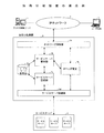
複数の伝送路を備えるローカルエリアネットワーク(LAN)において,伝送アクセス制御フレームの順序制御及びコンピュータの上位レベルのソフトウェアによる伝送路選択を不要にする方法が提案されている(特許文献1参照)。その内容を図9の従来例1の構成として示す。ステーション50において,コンピュータインタフェース51はコンピュータ57からのリンク設定コマンドやデータ転送コマンドを受け付けてインタフェース機能を果たす。各伝送路56に対応して設けられた伝送路負荷計測部54は対応する伝送路56を介してステーション50で受信または中継されるフレームの単位時間当たりの数を計数して,各伝送路56の負荷を計測する。
In a local area network (LAN) having a plurality of transmission paths, a method has been proposed in which the order control of transmission access control frames and transmission path selection by higher-level software of a computer are not required (see Patent Document 1). The contents are shown as the configuration of Conventional Example 1 in FIG. In the
コンピュータ57からステーション50に対してリンク設定要求のコマンドを送ると,コンピュータインタフェース51を介して通信制御部52で受け付け,リンク制御部52bは伝送路の選択を行う。伝送路の選択は,各伝送路負荷計測部54で計測された各伝送路56の負荷を参照し,最も負荷の少ない伝送路を選択して通信テーブル52cに書き込み,伝送路切替え部52dを選択した伝送路側に切り替え,対応する伝送アクセス制御部53,物理レベルプロトコル部55を介してリンク設定要求フレームを伝送路に送り出して,相手ステーションからの応答を受け取ることでリンク設定が行われる。
When a link setting request command is sent from the
この方法により,リンク設定時に最も負荷の少ない伝送路を選択してその伝送路にリンクを割り当て,伝送路の負荷に応じてリンクを均等に配分して効率的に複数の伝送路を使用できる。なお,このように各伝送路(または処理装置)の負荷を計測して,新たな要求に対して負荷の少ない伝送路(処理装置)を選択する機能を備える機構を負荷分散装置(またはロードバランサ)と呼ばれる。 By this method, it is possible to efficiently use a plurality of transmission paths by selecting a transmission path with the least load at the time of link setting, assigning a link to the transmission path, and evenly allocating the link according to the load of the transmission path. It should be noted that a mechanism having a function of measuring the load on each transmission path (or processing device) and selecting a transmission path (processing device) with a low load in response to a new request in this manner is provided as a load balancer (or load balancer). ).
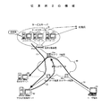
一方,動的オブジェクトを再利用でき,トラヒックの軽減を図ると共にユーザに与える負担を軽減できて快適にサービスを受けることができるネットワークアクセス制御方法及びそれを用いたネットワークシステム及びそれを構成する装置が提案されている(特許文献2参照)。その提案された方法の中にインターネットサービスプロバイダが受付代行サービスを行う構成が含まれ,その方法の概要を従来例2の構成として図10に示す。 On the other hand, there is provided a network access control method capable of reusing a dynamic object, reducing traffic and reducing a burden on a user and receiving a service comfortably, a network system using the same, and an apparatus constituting the network access control method It has been proposed (see Patent Document 2). The proposed method includes a configuration in which an Internet service provider performs an acceptance service, and an overview of the method is shown in FIG.
図10の構成では,IPネットワーク(インターネット)60にインターネットサービスプロバイダの複数台のサービスサーバ61a〜61cがルータ等のネットワーク装置61e及び負荷分散装置(ロードバランサと呼ばれる場合もある)61dを介して接続され,サービスサーバ61へのトラヒックが集中した場合に備えて,アクセス制御サーバ(または受付サーバ)62を設けたものである。この構成においてサービスサーバが高負荷になった場合,図10に示す(1) 〜(3) の動作が実行される。
In the configuration of FIG. 10, a plurality of service servers 61a to 61c of an Internet service provider are connected to an IP network (Internet) 60 via a
(1) サービスサーバ61が快適にユーザ端末64からの要求を処理できるか否かの情報として,CPUの使用率が閾値を越えた時に,アクセス制御サーバ62に高負荷状態であることを通知する。なお,CPUの使用率が閾値より下回ったときは,低負荷になったことを通知する。
(1) As information on whether or not the
(2) 1台のサービスサーバから高負荷通知を受けたアクセス制御サーバ62は,その他のサービスサーバが低負荷で処理余力があったとしても,ネットワーク装置61eに対してユーザ端末の要求を待合せサーバ63に迂回するよう指示する。
(2) The
(3) ネットワーク装置61eは,新たなユーザ端末の要求を受けると,待合せサーバ63に迂回接続する。サービスサーバ61は快適にユーザ端末64からのアクセス要求を処理できるか否かの情報として,CPUの使用率が閾値を越えた時に,アクセス制御サーバ62に対して高負荷状態であることを通知する(CPUの使用率が閾値より下回った時も低負荷になったことを通知する。1台のサービスサーバ(61a〜61cの何れか)より高負荷通知を受けたアクセス制御サーバ62は,その他のサービスサーバが低負荷で処理余力があったとしても,ネットワーク装置61eに対しユーザ端末の要求を待合せサーバ63に迂回するように指示を出す。待合わせサーバ63はサービスサーバの状態を見て先頭の待ち合せから順番に取り出してサービスサーバへアクセスを可能にする制御を行う。
上記した従来例1の構成では負荷分散装置(ロードバランサ)では負荷を計測して,要求があると最も負荷の軽いものを選択している。そして,負荷分散装置(ロードバランサ)による負荷分散方法として,従来,アクセス要求を複数の処理装置に対し順番に割り振る「ラウンドロビン」,予め各処理装置の処理能力に応じて処理個数を設定しておいて,その処理個数分ずつ割り当てる「重み付けラウンドロビン」,各処理装置に予め優先順位を割り当てて要求があるとその優先順位に従って割り当てる「優先順位」,現在の各処理装置への接続数を見て少ない処理装置へ割り当てる「接続数」,問い合わせに対する応答時間の早いものを割り当てる「応答時間」,サーバに対して要求するサービス内容に応じてHTTPヘッダを識別して対応するサーバに割り当てる「HTTPヘッダ」,といった各種のアルゴリズムにより分散を行っている。しかし,これらのアルゴリズムを用いたとしても,負荷分散装置の配下にある複数の処理装置の処理能力を越える要求には対応できないという問題があった。 In the configuration of Conventional Example 1 described above, the load distribution device (load balancer) measures the load and selects the lightest load when requested. As a load balancing method by a load balancer (load balancer), conventionally, “round robin” in which access requests are sequentially allocated to a plurality of processing devices, the number of processing is set in advance according to the processing capacity of each processing device. In this case, the “weighted round robin” assigned for each processing number, the priority order assigned to each processing device in advance and the “priority order” assigned according to the priority when requested, the current number of connections to each processing device are checked. "Number of connections" to be assigned to a small number of processing devices, "response time" to assign one with a quick response time to an inquiry, and "HTTP header" to identify an HTTP header according to the service content requested to the server and assign it to the corresponding server "Is distributed by various algorithms such as. However, even if these algorithms are used, there is a problem that requests exceeding the processing capability of a plurality of processing devices under the load balancer cannot be handled.
このような処理装置の処理能力を越えた要求があった場合,その要求を待ち合せサーバに迂回させる技術として,上記の従来例2の構成として示すアクセス制御による待ち合せ方式が提案されている。しかし,このアクセス制御による待合せ方式を用いても,CPU使用率を見ているだけなので,複数のサーバで構成されるような場合の負荷分散装置に十分対応できていない。 As a technique for bypassing the request to the queuing server when there is a request that exceeds the processing capability of such a processing apparatus, a queuing method based on access control shown as the configuration of the conventional example 2 has been proposed. However, even if this queuing method based on access control is used, the CPU usage rate is only observed, so that it is not sufficiently compatible with a load balancer in the case of a plurality of servers.
例えば,ラウンドロビンによる負荷分散装置を考えると,サーバA,サーバB,サーバCが負荷分散装置で負荷分散されても単純に処理要求を分散されるだけなので,サーバAだけに処理の重いものが集中して,サーバBやサーバCが処理できるにも関わらず,待合せサーバに迂回させてしまうという問題がある。また,重み付けラウンドロビン,優先順位,接続数,応答時間,HTTPヘッダ,等により分散を行った場合でも同じような問題が起こる。 For example, considering a round-robin load balancer, even if server A, server B, and server C are load-balanced by the load balancer, processing requests are simply distributed. There is a problem that although the servers B and C can be processed in a concentrated manner, the server is detoured. The same problem occurs even when distributed by weighted round robin, priority, number of connections, response time, HTTP header, and the like.
本発明は負荷分散装置を制御する機能を用いてサービスサーバを最適に動作させることができるネットワークアクセス制御システムを提供することを目的とする。 An object of the present invention is to provide a network access control system capable of operating a service server optimally using a function for controlling a load balancer.
図1は本発明の原理構成である。図中,1はアクセス制御サーバ,10はサーバ監視部,11はユーザ端末からのサービスサーバ6へのアクセス要求に対しサービスサーバ6へ接続するか,待合せサーバ3へ接続するかを決定する接続先決定部,12は負荷分散装置情報収集部,13は安定運用管理部,14は負荷分散装置設定変更部,15はネットワーク制御部,16はサービスサーバ6の状態や負荷分散装置5の状態を管理する状態管理データベース(DB),17はサービスサーバ6や負荷分散装置5の安定運用のための情報(詳細は後述する)が登録された安定運用管理データベース(DB),18は安定運用管理DB17の設定内容の変更を行う安定運用設定変更部,19は保守端末,2aはアクセス制御サーバ1と後述する待合せサーバ3をIPネットワーク4に接続するルータ等のネットワーク装置,2bはサービスサーバ6をIPネットワーク4に接続するネットワーク装置,2cはユーザ端末側をIPネットワーク4に接続するネットワーク装置,3は待合せサーバ,4はIPネットワーク,5は負荷分散装置,6はサービスサーバであり,6a,6b,6cはそれぞれサービスサーバを構成する複数(この例では3台)のサーバ♯A,サーバ♯B,サーバ♯C,7はユーザ端末である。なお,サービスサーバ6は1つのシステムだけ示されているが,複数個設けられる場合もある。
FIG. 1 shows the principle configuration of the present invention. In the figure, 1 is an access control server, 10 is a server monitoring unit, 11 is a connection destination for determining whether to connect to the
本発明は負荷分散装置(ロードバランサ)の振る舞いを識別してアクセス制御による待合せを行うもので,アクセス制御による待合せに移行するのは,負荷分散装置による複数のサーバで運用される場合に,これ以上のアクセスを受付けると安定運用ができなくると判断した場合に限られる。従って,本発明は負荷分散装置から定期的に情報収集する手段と,その収集情報からサービスサーバの負荷を均一にするために負荷分散装置の振り分けを設定を変更する手段を備え,全てのサービスサーバが高負荷になった時にアクセス制御による待合せサーバに迂回することで,負荷分散装置を備えた環境においても安定運用が可能となる。 The present invention identifies the behavior of the load balancer (load balancer) and performs queuing by access control. The reason for shifting to queuing by access control is when operating on a plurality of servers by the load balancer. It is limited to the case where it is judged that stable operation cannot be performed if the above access is accepted. Therefore, the present invention comprises means for periodically collecting information from the load balancer, and means for changing the setting of the load balancer distribution in order to make the load of the service server uniform from the collected information. By detouring to a queuing server by access control when the load becomes high, stable operation is possible even in an environment equipped with a load balancer.
本発明はユーザ端末7からサービスサーバ6へのアクセス要求は負荷分散装置5で受け付けられる。一方,サービスサーバ6が快適にユーザ端末7からの要求を処理できるか否かを表す情報として各サーバ♯A〜♯CのCPUの使用率が閾値を越えた時にアクセス制御サーバ1に高負荷状態であることを通知し,CPUの使用率が閾値を下回った時は低負荷になったことを通知する。アクセス制御サーバ1のサーバ監視部10はこの通知を受信すると,その状態を状態管理DB16に登録する。
In the present invention, an access request from the
アクセス制御サーバ1の安定運用管理DB17には,予め保守端末19から負荷分散装置5による負荷分散のための各種の条件(応答時間,優先度,重み,等)や数値を画面を見ながら設定を行うと,安定運用設定変更部18により安定運用管理DB17に格納される。負荷分散装置情報収集部12はこの安定運用管理DB17に設定された項目について,定期的にIPネットワーク4を介して負荷分散装置5が管理している情報を要求し,負荷分散装置5から収集した情報を状態管理DB16に格納し,安定運用管理部に収集完了の通知を行う。安定運用管理部13は状態管理DB16から収集結果を参照し,参照結果で規定値をオーバーした値や変化が大きい値があると,詳細なデータを収集するため負荷分散装置情報収集部12に追加のデータ収集の要求を行い,追加して収集したデータは状態管理DB16に登録する。また,収集した情報を元にサービスサーバの負荷(一つのサービスサーバ6内の複数のサーバA〜Cの負荷)を均一にするため負荷分散装置5の設定を変更する必要があると判断した場合は,負荷分散装置設定変更部14に対し設定変更の通知を行う。
In the stable
安定運用管理部13より設定変更の指示を受けた負荷分散装置設定変更部14は負荷分散装置5に対して設定変更の制御を行い,制御結果を安定運用管理部13に供給する。
Upon receiving the setting change instruction from the stable
この時,変更される負荷分散装置5の設定情報としては,負荷分散制御のための各種の設定値(応答時間,優先度,重み,等)がある。安定運用管理DB17に設定されるサービスサーバ6や負荷分散装置5に対する設定情報は,保守端末19からの入力により安定運用設定変更部18から変更することができる。
At this time, the setting information of the
負荷分散装置5に対する設定変更を実行しても,サービスサーバ6の全てのサーバが高負荷になると,アクセス制御サーバ1の接続先決定部11は状態管理DB16と安定運用管理DB17から高負荷状態を検出すると,ユーザ端末7からのアクセス要求を待合せサーバ3に迂回させるようネットワーク制御部15に対して指示を発生し,この指示によりネットワーク制御部15はサービスサーバ6及び負荷分散装置5が接続されたネットワーク装置2bに対し,ユーザ端末7からのアクセス要求を待合せサーバ3に迂回接続するよう制御し,該アクセス要求を待合せ状態(待機状態)にさせる。なお,一台でも高負荷でないサーバがあると負荷分散装置5への接続を可能にする。
Even if the setting change for the
本発明により,負荷分散装置を制御する機能を備えることで,負荷分散装置を必要とするサービスサーバを備える施設の資源を有効に利用してユーザサービスを提供することができる。また,サービスサーバの負荷状況やトラヒック状況を定期的に監視するので,サービスサーバが最適に動作可能なアクセス数分だけユーザに許可することが可能となる。 According to the present invention, it is possible to provide a user service by effectively using resources of a facility including a service server that requires a load balancer by providing a function for controlling the load balancer. In addition, since the load status and traffic status of the service server are regularly monitored, it is possible to allow the user only for the number of accesses that the service server can operate optimally.
また,本発明を適用すれば遠隔から負荷分散装置の最適化や運用状況レポート出力など負荷分散の適正化サービスの実現が可能となる。更に,本発明の適用により既設の負荷分散装置の処理能力に合わせたサービスの提供が可能となる。 Further, by applying the present invention, it is possible to realize a load balancing optimization service such as optimization of a load balancer and operation status report output from a remote location. Furthermore, the application of the present invention makes it possible to provide a service that matches the processing capacity of an existing load balancer.
図2は本発明が実施されるシステム構成図である。図中,1,2a,2c,3,4,7はそれぞれ上記図1の同一符号の各部と同様であり,1はアクセス制御サーバ,2a,2cはルータ等のネットワーク装置,3は待合せサーバ,4はIPネットワークである。図2ではサービスサーバが2セット設けられている例であり,それに対応してネットワーク装置2b−1,2b−2,負荷分散装置5−1,5−2及びサービスサーバ6−1,6−2がそれぞれ設けられている。各サービスサーバ6−1,6−2の内部にはそれぞれサーバ♯A,サーバ♯B,サーバ♯Cの3台が設けられている。アクセス制御サーバ1は上記図1に示す各部の機能を実現する構成を備えている。
FIG. 2 is a system configuration diagram in which the present invention is implemented. In the figure, 1, 2 a, 2 c, 3, 4, and 7 are the same as the parts having the same reference numerals in FIG.
最初にアクセス制御サーバ1の安定運用管理DB(図1の17)に対し,情報を収集すべきサービスサーバの情報と負荷分散装置での安定運用管理のために負荷分散装置から収集する情報の項目を設定する。
Items of information collected from the load balancer for the stable operation management in the load balancer and the information on the service server that should collect the information first with respect to the stable operation management DB (17 in FIG. 1) of the
図3は安定運用管理DBのテーブル構成を示し,図3のA.はサービスサーバ情報であり,対象となるサービスサーバの中の各サーバについて固有情報が設定されており,サーバの固有情報としては,サービスサーバID,サービスサーバ名,サービスサーバIPアドレス,サービスサーバポート番号,負荷分散装置ID(該当サービスサーバの入力側に設けられた負荷分散装置のID),サービスサイトURL,CPU使用率の閾値(この閾値を越えると過負荷とする)等により構成される。図3のB.は負荷分散装置情報であり,各負荷分散装置毎に固有情報と収集可能情報の2種類の情報が設定され,負荷分散装置の固有情報としては負荷分散装置ID,負荷分散装置名,MIB情報(Management Infomation Base: ネットワーク装置と負荷分散装置間のネットワーク管理プロトコルであるSNMP(Simple Network Management Protocol)で使用するデータ),要求ポート番号,応答ポート番号の各情報により構成される。 3 shows a table configuration of the stable operation management DB. Is service server information, and specific information is set for each server in the target service server. The server specific information includes service server ID, service server name, service server IP address, and service server port number. , Load balancer ID (ID of the load balancer provided on the input side of the corresponding service server), service site URL, threshold of CPU usage rate (exceeding this threshold causes overload), and the like. B. of FIG. Is load balancer information, and two types of information, unique information and collectable information, are set for each load balancer. The load balancer ID, load balancer name, MIB information ( Management Infomation Base: Consists of information on SNMP (Simple Network Management Protocol) which is a network management protocol between the network device and the load balancer, request port number, and response port number.
負荷分散装置の収集指定情報は,各行(アドレス)に対して収集すべき項目が定義され,先頭に自CPU使用率(負荷分散装置自身のCPU),各サービスサーバのCPU使用率,各セッション数(IPネットワークと負荷分散装置間のセッション数),各応答時間(各サービスサーバの),優先度,重み,次接続サービスサーバ(次にアクセスを受けた時に接続する予定のサービスサーバ)が定義され,これらの各項目に対応する領域に収集すべき項目なら“1”,収集しない項目なら“0”が設定される。 The collection specification information of the load balancer defines items to be collected for each row (address), and starts with its own CPU usage rate (the CPU of the load balancer itself), the CPU usage rate of each service server, and the number of sessions. (Number of sessions between the IP network and the load balancer), each response time (for each service server), priority, weight, and next connection service server (the service server to be connected when the next access is received) are defined “1” is set for an item to be collected in an area corresponding to each of these items, and “0” is set for an item not to be collected.
図4は負荷分散装置からの情報収集の処理フローを示す。 FIG. 4 shows a processing flow for collecting information from the load balancer.
アクセス制御サーバ(図1,図2の1)の負荷分散装置情報収集部(図1の12)は,安定運用管理DB(図1の17,図3参照)に設定された負荷分散装置に関して設定された項目から収集すべき項目(“1”が設定された項目)を決定し(図4のS1),決定した項目の収集要求をサービスサーバに対応して設けられた負荷分散装置に対して送出する(同S2)。この収集要求を受けた負荷分散装置から要求された項目に対応した負荷分散装置の状態を表す情報を含む収集応答が返ってくると,収集したデータを状態管理DB(図1の16)に登録し(図4のS3),収集完了通知を安定運用管理部(図1の13)に通知する(図4のS4)。なお,負荷分散装置から収集する項目により,収集する周期を変更してもよい。これにより,変動の大きい重要な項目については短い周期で収集し,変動が少ないか,重要度の低い項目については長い周期で収集することで,収集のための処理負担を減らすことができる。 The load balancer information collection unit (12 in FIG. 1) of the access control server (1 in FIGS. 1 and 2) is set for the load balancer set in the stable operation management DB (see FIGS. 17 and 3 in FIG. 1). Items to be collected (items for which “1” is set) are determined (S1 in FIG. 4), and a collection request for the determined items is sent to the load balancer provided corresponding to the service server. (S2). When a collection response including information indicating the state of the load balancer corresponding to the item requested from the load balancer that has received this collection request is returned, the collected data is registered in the state management DB (16 in FIG. 1). (S3 in FIG. 4), a notification of completion of collection is sent to the stable operation management unit (13 in FIG. 1) (S4 in FIG. 4). The collection period may be changed according to the items collected from the load balancer. Thereby, it is possible to reduce the processing load for collection by collecting important items with large fluctuations in a short cycle and collecting items with little fluctuation or low importance in a long cycle.
図5は状態管理DBのテーブル構成を示す。この状態管理DB(図1の16)には,図5のA.に示すようにサービスサーバから送られてくるサービスサーバ状態情報が格納され,各サービスサーバについて,サービスサーバID,収集日時,状態(○なら使用率が閾値より低い状態で,×なら閾値以上の状態)が格納されている。なお,この○,×の「状態」は,上記安定運用管理DBの中のサービスサーバ情報の固有情報として閾値が登録されており,サービスサーバから使用率を収集した時に,アクセス制御サーバでこの登録された閾値と比較して設定する。図5のB.は負荷分散装置情報であり,上記図4で説明した負荷分散装置情報収集部の動作により収集した各項目のデータが格納され,各負荷分散装置収集情報として,負荷分散装置ID,収集日時,収集項目(この後に続く収集情報1,収集情報2,…の各項目の定義),収集情報1,収集情報2,…の各収集情報が登録される。
FIG. 5 shows a table configuration of the state management DB. In this state management DB (16 in FIG. 1), A. of FIG. Service server status information sent from the service server is stored as shown in Fig. 3. For each service server, the service server ID, collection date and state (○ indicates that the usage rate is lower than the threshold, and × indicates that the threshold is above the threshold. ) Is stored. The “status” of ○ and × has a threshold registered as unique information of the service server information in the above stable operation management DB. When the usage rate is collected from the service server, this is registered on the access control server. It is set in comparison with the threshold value. B. of FIG. Is the load balancer information, which stores the data of each item collected by the operation of the load balancer information collection unit described in FIG. 4, and as each load balancer collection information, the load balancer ID, the collection date and time, the collection Each item of collection information (
図6は負荷分散装置からの追加情報収集の処理フローを示す。上記図4の処理により負荷分散装置情報収集部からの情報収集が実行されて収集完了通知を受けた安定運用管理部(図1の13)は,負荷分散装置から収集したデータ(上記図5の状態管理DBのテーブル)を参照し(図6のS1),データの変動が大きく変動した(誤っている可能性がある)場合や,必要なデータが不足しているか判別し,そのような項目が存在することを検出すると(同S2),該当する項目について追加収集の依頼を負荷分散装置情報収集部に対して依頼をする(同S3)。なお,安定運用管理DBへの新規項目の設定は,アクセス制御サーバに接続された保守端末(図示省略)から保守者により画面を見ながら行う。 FIG. 6 shows a processing flow for collecting additional information from the load balancer. When the information collection from the load balancer information collection unit is executed by the processing of FIG. 4 and the collection completion notification is received, the stable operation management unit (13 in FIG. 1) collects the data collected from the load balancer (FIG. 5 above). Refer to the state management DB table (S1 in FIG. 6) to determine if the data fluctuation has fluctuated greatly (possibly incorrect) or whether the necessary data is insufficient, and such items Is detected (S2), an additional collection request for the corresponding item is requested to the load balancer information collection unit (S3). The setting of new items in the stable operation management DB is performed by a maintenance person looking at the screen from a maintenance terminal (not shown) connected to the access control server.
この追加収集の依頼を受けた負荷分散装置情報収集部は,負荷分散装置に対して追加収集要求を送出し(図6のS4),負荷分散装置から収集応答が返ってくると収集したデータを状態管理データに登録し(同S5),収集完了通知を安定運用管理部に送る(同S6)。 Upon receiving this request for additional collection, the load balancer information collection unit sends an additional collection request to the load balancer (S4 in FIG. 6), and collects data when a collection response is returned from the load balancer. It registers in the state management data (S5), and sends a collection completion notification to the stable operation management unit (S6).
図7は負荷分散装置の設定変更の処理フローを示す。 FIG. 7 shows a processing flow for changing the setting of the load balancer.
アクセス制御サーバの安定運用管理部において,状態管理DBと安定運用管理DBから,サービスサーバの状態(CPUの使用率等)を参照し(図7のS1),ロードバランサに設定した負荷分散制御のための数値(優先度,重み等)を変更したり,定期的に収集する情報の項目を変更または追加することが必要,すなわち負荷分散装置における負荷分散制御のための設定変更が必要と判断されると,設定変更依頼を負荷分散装置設定変更部(図1の14)に発行する(図7のS2)。負荷分散装置設定変更部でこの設定変更依頼を受け取ると,設定変更要求を負荷分散装置に対し送信し(図7のS3),負荷分散装置がこの設定変更要求に含まれた内容によりデータの設定変更を行って,設定変更応答がアクセス制御サーバの負荷分散装置設定変更部で受け取ると,設定完了通知を安定運用管理部に通知する(同S4)。 The stable operation management unit of the access control server refers to the state of the service server (CPU usage rate, etc.) from the state management DB and the stable operation management DB (S1 in FIG. 7), and performs load balancing control set for the load balancer. It is necessary to change the numerical values (priority, weight, etc.) for this purpose, or to change or add items of information to be collected regularly, that is, it is determined that it is necessary to change the settings for load balancing control in the load balancer Then, a setting change request is issued to the load balancer setting changing unit (14 in FIG. 1) (S2 in FIG. 7). When the load balancer setting change unit receives this setting change request, it sends a setting change request to the load balancer (S3 in FIG. 7), and the load balancer sets data according to the contents included in the setting change request. When the change is made and the setting change response is received by the load balancer setting changing unit of the access control server, a setting completion notification is sent to the stable operation management unit (S4).
図8は負荷分散装置の構成例を示す。図中,1はアクセス制御サーバ,4はIPネットワーク,5は負荷分散装置,5は負荷分散装置,5aはIPネットワークを介してユーザ端末からのアクセスを受け付けるネットワーク接続部,5bはサービスサーバ管理データベース5fを参照してサービスサーバとの接続の制御を行うサービスサーバ管理部,5cはサービスサーバ監視部,5dはIPネットワークからアクセスしてきたユーザ端末からの要求をサービスサーバへ接続する制御を行うサービスサーバ接続部,5eはIPヘッダ変更部,5fはサービスサーバ管理データベース(DB),複数のサーバを含むサービスサーバ,7はユーザ端末である。 FIG. 8 shows a configuration example of the load distribution apparatus. In the figure, 1 is an access control server, 4 is an IP network, 5 is a load balancer, 5 is a load balancer, 5a is a network connection unit for accepting access from a user terminal via the IP network, and 5b is a service server management database. 5f is a service server management unit that controls connection to the service server, 5c is a service server monitoring unit, and 5d is a service server that performs control to connect a request from a user terminal accessed from the IP network to the service server. A connection unit, 5e is an IP header changing unit, 5f is a service server management database (DB), a service server including a plurality of servers, and 7 is a user terminal.
この負荷分散装置5とアクセス制御サーバ1及びユーザ端末7の相互動作による情報収集,負荷分散装置の設定変更及びサービスサーバとの接続の各動作を以下に説明する。
Each operation of information collection, setting change of the load balancer, and connection with the service server by the mutual operation of the
(1) アクセス制御サーバ1からの情報収集及び追加情報収集の動作
負荷分散装置5のサービスサーバ管理部5bはサービスサーバ監視部5cを駆動すると,サービスサーバ監視部5cはサービスサーバ接続部5dを介してサービスサーバ6(複数のサービスサーバを含む)から順に情報を収集し,収集した情報をサービスサーバ管理DB5fに登録する。アクセス制御サーバ1から負荷分散装置5に情報収集の依頼が送られてくると,ネットワーク接続部5aを介してサービスサーバ管理部5bで受け取られ,サービスサーバ管理DB5fに登録された負荷分散装置で管理する情報を取り出して,アクセス制御サーバ1に送信される。
(1) Operation for collecting information from the
(2) アクセス制御サーバ1から負荷分散装置5の設定変更
アクセス制御サーバ1から負荷分散装置5のネットワーク接続部5aを介してサービスサーバ管理部5bに対して設定変更を指示することで,サービスサーバ管理部5bはサービスサーバ管理DB5fの設定情報を指示された情報に変更する。
(2) Changing the setting of the
(3) ユーザ端末7からサービスサーバ6への接続
ユーザ端末7がIPネットワーク4を介してサービスサーバ6にアクセスすると,ネットワーク接続部5aはIPヘッダ変更部5eを駆動する。IPヘッダ変更部5eは,サービスサーバ管理部5bによるサービスサーバ管理DB5fを参照したどのサービスサーバに接続すべきかの情報を収集する。接続すべきサービスサーバの情報を得られると,IPヘッダの宛先を取得したサービスサーバの情報に変更しサービスサーバ接続部5dからサービスサーバ6に接続する。
(3) Connection from
サービスサーバ6からの情報は負荷分散装置5のサービスサーバ接続部5dからIPヘッダ変更部5eで受け取ると,そのIPヘッダの送信元をサービスサーバ6から負荷分散装置5に変更して,ネットワーク接続部5aを介してユーザ端末7へ送信する。
When the information from the
(付記1) ユーザ端末からのサービスサーバへのアクセスを負荷分散装置に設定された制御情報により複数のサーバの一つへ分散し,前記負荷分散装置に対する監視制御をアクセス制御サーバにより行うIPネットワークにおけるアクセス制御方式において,前記アクセス制御サーバは,前記サービスサーバから各サーバの負荷状態を収集するサーバ監視部と,設定された制御・管理の項目を保持する安定運用管理データベースと,前記安定運用管理データベースに設定された項目について前記負荷分散装置における状態を収集する負荷分散装置情報収集部と,前記サーバ監視部及び負荷分散装置情報収集部で収集した各情報を保持する状態管理データベースと,前記安定運用管理データベースの設定情報とを参照して,サービスサーバの負荷が均一になるよう負荷分散装置の振り分け設定の変更を指示する安定運用管理部と,を備えることを特徴とするIPネットワークにおけるアクセス制御方式。 (Appendix 1) In an IP network in which access to a service server from a user terminal is distributed to one of a plurality of servers by control information set in the load balancer, and monitoring control for the load balancer is performed by the access control server In the access control method, the access control server includes a server monitoring unit that collects a load state of each server from the service server, a stable operation management database that holds set control / management items, and the stable operation management database. A load balancer information collection unit that collects the state of the load balancer for the items set in the item, a state management database that holds information collected by the server monitoring unit and the load balancer information collection unit, and the stable operation Refer to the setting information of the management database. Access Control in an IP network, characterized in that it comprises a stable operation management unit for instructing to change the distribution setting of the load balancer to load is uniform, the.
(付記2) 付記1において,前記負荷分散装置及び前記アクセス制御サーバは,それぞれルータ等のネットワーク装置を介してIPネットワークと接続され,前記各ネットワーク装置の制御を前記アクセス制御サーバにより行うことを特徴とするIPネットワークにおけるアクセス制御方式。
(Supplementary Note 2) In
(付記3) 付記1において,前記アクセス制御サーバは,前記状態管理データベースの前記負荷分散装置から収集されたデータを参照し,追加して収集すべき項目を検出すると前記負荷分散装置情報収集部に追加収集依頼を発行し,追加収集したデータを前記状態管理データベースに登録することを特徴とするIPネットワークにおけるアクセス制御方式。
(Supplementary note 3) In
(付記4) 付記1において,前記アクセス制御サーバは,前記負荷分散装置に設定された制御情報を変更する入力を行うための保守端末と,前記保守端末からの入力を前記安全運用管理データベースに格納する安定運用設定変更部と,を備えることを特徴とするIPネットワークにおけるアクセス制御方式。
(Additional remark 4) In
(付記5) 付記1または2の何れかにおいて,前記負荷分散装置に設定される制御情報は,各サービスサーバの負荷分散装置とのセッション数,応答時間,優先度,重み等の情報を含むことを特徴とするIPネットワークにおけるアクセス制御方式。
(Supplementary Note 5) In any one of
(付記6) 付記2において,前記アクセス制御サーバは,ユーザ端末からのサービスサーバへのアクセス要求に対し,前記状態管理データベース及び安定運用管理データベースの内容を参照して,前記負荷分散装置に設定する制御情報を安定運用設定変更部で変更してもサービスサーバの処理能力を越えると前記アクセス要求を待合せサーバへ接続先変更を行い,サービスサーバの処理能力を越えないと前記サービスサーバに接続する決定を行う接続先決定部と,前記接続先決定部の決定に従ってネットワーク制御を行うネットワーク制御部と,を備えることを特徴とするIPネットワークにおけるアクセス制御方式。 (Supplementary Note 6) In Supplementary Note 2, the access control server refers to the contents of the state management database and the stable operation management database in response to an access request from the user terminal to the service server, and sets it in the load balancer. Even if the control information is changed by the stable operation setting changing unit, if the processing capacity of the service server is exceeded, the access request is changed to the queuing server, and if the service server processing capacity is not exceeded, the connection to the service server is decided. An access control method in an IP network, comprising: a connection destination determination unit that performs network control; and a network control unit that performs network control according to the determination of the connection destination determination unit.
(付記7) 付記1において,前記アクセス制御サーバの負荷分散装置情報収集部は,予め安定運用管理データベースに設定された収集すべき情報項目に応じて,異なる周期で収集を行うことを特徴とするIPネットワークにおけるアクセス制御方式。
(Additional remark 7) In
1 アクセス制御サーバ
10 サーバ監視部
11 接続先決定部
12 負荷分散装置情報収集部
13 安定運用管理部
14 負荷分散装置設定変更部
15 ネットワーク制御部
16 状態管理データベース(DB)
17 安定運用管理データベース(DB)
18 安定運用設定変更部
19 保守端末
2a〜2c ネットワーク装置
3 待合せサーバ
4 IPネットワーク
5 負荷分散装置
6 サービスサーバ
7 ユーザ端末
DESCRIPTION OF
17 Stable operation management database (DB)
DESCRIPTION OF
Claims (4)
前記アクセス制御サーバは,前記サービスサーバから各サーバの負荷状態を収集するサーバ監視部と,設定された制御・管理の項目を保持する安定運用管理データベースと,前記安定運用管理データベースに設定された項目について前記負荷分散装置における状態を収集する負荷分散装置情報収集部と,前記サーバ監視部及び負荷分散装置情報収集部で収集した各情報を保持する状態管理データベースと,前記安定運用管理データベースの設定情報とを参照して,サービスサーバの負荷が均一になるよう負荷分散装置の振り分け設定の変更を指示する安定運用管理部と,
を備えることを特徴とするIPネットワークにおけるアクセス制御方式。 In an access control method in an IP network in which access to a service server from a user terminal is distributed to one of a plurality of servers by control information set in the load balancer, and monitoring control for the load balancer is performed by the access control server ,
The access control server includes a server monitoring unit that collects a load state of each server from the service server, a stable operation management database that holds set control / management items, and items set in the stable operation management database. A load balancer information collection unit for collecting states in the load balancer, a state management database for holding information collected by the server monitoring unit and the load balancer information collection unit, and setting information for the stable operation management database And a stable operation management unit that instructs to change the distribution setting of the load balancer so that the load on the service server is uniform,
An access control method in an IP network, comprising:
前記アクセス制御サーバは,前記状態管理データベースの前記負荷分散装置から収集されたデータを参照し,追加して収集すべき項目を検出すると前記負荷分散装置情報収集部に追加収集依頼を発行し,追加収集したデータ前記状態管理データベースに登録することを特徴とするIPネットワークにおけるアクセス制御方式。 In claim 1,
The access control server refers to the data collected from the load balancer in the state management database, and issues an additional collection request to the load balancer information collection unit when an item to be collected is detected. An access control method in an IP network, wherein the collected data is registered in the state management database.
前記アクセス制御サーバは,前記負荷分散装置に設定された制御情報を変更する入力を 行うための保守端末と,前記保守端末からの入力を前記安全運用管理データベースに格納する安定運用設定変更部と,
を備えることを特徴とするIPネットワークにおけるアクセス制御方式。 In claim 1,
The access control server includes a maintenance terminal for performing input for changing control information set in the load balancer, a stable operation setting changing unit for storing input from the maintenance terminal in the safe operation management database,
An access control method in an IP network, comprising:
前記アクセス制御サーバは,ユーザ端末からのサービスサーバへのアクセス要求に対し,前記状態管理データベース及び安定運用管理データベースの内容を参照して,前記負荷分散装置に設定する制御情報を安定運用設定変更部で変更してもサービスサーバの処理能力を越えると前記アクセス要求を待合わせサーバへ接続先変更を行い,サービスサーバの処理能力を越えないと前記サービスサーバに接続する決定を行う接続先決定部と,前記接続先決定部の決定に従ってネットワーク制御を行うネットワーク制御部と,
を備えることを特徴とするIPネットワークにおけるアクセス制御方式。 In claim 2,
The access control server refers to the contents of the state management database and the stable operation management database in response to an access request from the user terminal to the service server, and sets control information to be set in the load balancer to a stable operation setting change unit. A connection destination determination unit that changes the connection destination to the queuing server when the service server processing capacity is exceeded even if the service server is changed, and determines that connection to the service server is made if the service server processing capacity is not exceeded. A network control unit that performs network control according to the determination of the connection destination determination unit;
An access control method in an IP network, comprising:
Priority Applications (1)
| Application Number | Priority Date | Filing Date | Title |
|---|---|---|---|
| JP2003426388A JP2005182702A (en) | 2003-12-24 | 2003-12-24 | Access control system in ip network |
Applications Claiming Priority (1)
| Application Number | Priority Date | Filing Date | Title |
|---|---|---|---|
| JP2003426388A JP2005182702A (en) | 2003-12-24 | 2003-12-24 | Access control system in ip network |
Publications (1)
| Publication Number | Publication Date |
|---|---|
| JP2005182702A true JP2005182702A (en) | 2005-07-07 |
Family
ID=34785943
Family Applications (1)
| Application Number | Title | Priority Date | Filing Date |
|---|---|---|---|
| JP2003426388A Withdrawn JP2005182702A (en) | 2003-12-24 | 2003-12-24 | Access control system in ip network |
Country Status (1)
| Country | Link |
|---|---|
| JP (1) | JP2005182702A (en) |
Cited By (11)
| Publication number | Priority date | Publication date | Assignee | Title |
|---|---|---|---|---|
| WO2007026633A1 (en) * | 2005-08-31 | 2007-03-08 | Daikin Industries, Ltd. | Communication program, communication method, equipment managing apparatus and remote management system |
| KR100870166B1 (en) | 2006-09-21 | 2008-11-25 | 후지쯔 가부시끼가이샤 | Load distributing apparatus, load distributing method, and load distributing program |
| JP2009140212A (en) * | 2007-12-06 | 2009-06-25 | Mitsubishi Electric Corp | Communication relay apparatus, server, client, network system, and communication method |
| WO2009101908A1 (en) * | 2008-02-13 | 2009-08-20 | Nec Corporation | Monitor manager, general manager, and node monitor system |
| JP2011186546A (en) * | 2010-03-04 | 2011-09-22 | Nec System Technologies Ltd | Load distribution system |
| JP2015506523A (en) * | 2012-02-03 | 2015-03-02 | マイクロソフト コーポレーション | Dynamic load balancing in a scalable environment |
| JP2015510187A (en) * | 2012-02-03 | 2015-04-02 | マイクロソフト コーポレーション | Partition management in a scalable environment |
| JP2016126743A (en) * | 2014-12-30 | 2016-07-11 | エヌエイチエヌ エンターテインメント コーポレーションNHN Entertainment Corporation | Cloud service providing method and system |
| US9852010B2 (en) | 2012-02-03 | 2017-12-26 | Microsoft Technology Licensing, Llc | Decoupling partitioning for scalability |
| JP2021086245A (en) * | 2019-11-26 | 2021-06-03 | ウイングアーク1st株式会社 | Chat system and chat management device |
| WO2022091259A1 (en) * | 2020-10-28 | 2022-05-05 | 日本電信電話株式会社 | Acceptance determining device and acceptance determining method |
-
2003
- 2003-12-24 JP JP2003426388A patent/JP2005182702A/en not_active Withdrawn
Cited By (15)
| Publication number | Priority date | Publication date | Assignee | Title |
|---|---|---|---|---|
| WO2007026633A1 (en) * | 2005-08-31 | 2007-03-08 | Daikin Industries, Ltd. | Communication program, communication method, equipment managing apparatus and remote management system |
| KR100870166B1 (en) | 2006-09-21 | 2008-11-25 | 후지쯔 가부시끼가이샤 | Load distributing apparatus, load distributing method, and load distributing program |
| JP2009140212A (en) * | 2007-12-06 | 2009-06-25 | Mitsubishi Electric Corp | Communication relay apparatus, server, client, network system, and communication method |
| WO2009101908A1 (en) * | 2008-02-13 | 2009-08-20 | Nec Corporation | Monitor manager, general manager, and node monitor system |
| JP5343863B2 (en) * | 2008-02-13 | 2013-11-13 | 日本電気株式会社 | Monitoring manager, general manager and node monitoring system |
| JP2011186546A (en) * | 2010-03-04 | 2011-09-22 | Nec System Technologies Ltd | Load distribution system |
| JP2015506523A (en) * | 2012-02-03 | 2015-03-02 | マイクロソフト コーポレーション | Dynamic load balancing in a scalable environment |
| JP2015510187A (en) * | 2012-02-03 | 2015-04-02 | マイクロソフト コーポレーション | Partition management in a scalable environment |
| US9852010B2 (en) | 2012-02-03 | 2017-12-26 | Microsoft Technology Licensing, Llc | Decoupling partitioning for scalability |
| US10635500B2 (en) | 2012-02-03 | 2020-04-28 | Microsoft Technology Licensing, Llc | Decoupling partitioning for scalability |
| US10860384B2 (en) | 2012-02-03 | 2020-12-08 | Microsoft Technology Licensing, Llc | Managing partitions in a scalable environment |
| JP2016126743A (en) * | 2014-12-30 | 2016-07-11 | エヌエイチエヌ エンターテインメント コーポレーションNHN Entertainment Corporation | Cloud service providing method and system |
| JP2021086245A (en) * | 2019-11-26 | 2021-06-03 | ウイングアーク1st株式会社 | Chat system and chat management device |
| JP7381305B2 (en) | 2019-11-26 | 2023-11-15 | ウイングアーク1st株式会社 | Chat system and chat management device |
| WO2022091259A1 (en) * | 2020-10-28 | 2022-05-05 | 日本電信電話株式会社 | Acceptance determining device and acceptance determining method |
Similar Documents
| Publication | Publication Date | Title |
|---|---|---|
| US11418620B2 (en) | Service request management | |
| CN103795805B (en) | Distributed server load-balancing method based on SDN | |
| CN109274707B (en) | Load scheduling method and device | |
| CN104272708B (en) | It is distributed with the stateless first order grouping to server farm and is distributed to the secondary data packets of the stateful second level grouping distribution of some server in group | |
| JP4523381B2 (en) | Packet communication device | |
| JP4984169B2 (en) | Load distribution program, load distribution method, load distribution apparatus, and system including the same | |
| JPH10307783A (en) | Site access control system and recording medium | |
| JP2004171572A (en) | Method, system and server for distributing load among servers, and program | |
| CN101076978B (en) | Method for distributing loads among servers | |
| CN101710905A (en) | Address resolution control method and system based on tactics | |
| JP2000268012A (en) | Method and device for distributing load in client server system | |
| JP4190455B2 (en) | Load balancing apparatus and program | |
| CN112202918B (en) | Load scheduling method, device, equipment and storage medium for long connection communication | |
| CN112350952B (en) | Controller distribution method and network service system | |
| CN112351083B (en) | Service processing method and network service system | |
| CN109407980A (en) | Data-storage system based on Redis cluster | |
| JP2005182702A (en) | Access control system in ip network | |
| JP2005182641A (en) | Dynamic load distribution system and dynamic load distribution method | |
| CN108234208A (en) | The visualization load balancing dispositions method and system of resource management based on business | |
| KR101448413B1 (en) | Method and apparatus for scheduling communication traffic in atca-based equipment | |
| CN113014611B (en) | Load balancing method and related equipment | |
| JP2003131960A (en) | Data relay method | |
| JP6131203B2 (en) | Device selection network system, device selection server and program | |
| CN112866394B (en) | Load balancing method, device, system, computer equipment and storage medium | |
| EP1816565B1 (en) | Computer system and information processing method |
Legal Events
| Date | Code | Title | Description |
|---|---|---|---|
| A300 | Application deemed to be withdrawn because no request for examination was validly filed |
Free format text: JAPANESE INTERMEDIATE CODE: A300 Effective date: 20070306 |