JP2005166047A - Mobile terminal with radio frequency identification tag and smart card combined, and radio identification method by mobile terminal - Google Patents
Mobile terminal with radio frequency identification tag and smart card combined, and radio identification method by mobile terminal Download PDFInfo
- Publication number
- JP2005166047A JP2005166047A JP2004338053A JP2004338053A JP2005166047A JP 2005166047 A JP2005166047 A JP 2005166047A JP 2004338053 A JP2004338053 A JP 2004338053A JP 2004338053 A JP2004338053 A JP 2004338053A JP 2005166047 A JP2005166047 A JP 2005166047A
- Authority
- JP
- Japan
- Prior art keywords
- radio frequency
- frequency identification
- smart card
- user information
- signal
- Prior art date
- Legal status (The legal status is an assumption and is not a legal conclusion. Google has not performed a legal analysis and makes no representation as to the accuracy of the status listed.)
- Pending
Links
- 238000000034 method Methods 0.000 title claims abstract description 28
- 230000010365 information processing Effects 0.000 claims abstract description 20
- 230000006870 function Effects 0.000 claims description 45
- 230000008859 change Effects 0.000 claims description 10
- 238000013459 approach Methods 0.000 claims description 8
- 238000012545 processing Methods 0.000 claims description 7
- 230000005540 biological transmission Effects 0.000 claims description 6
- 230000004044 response Effects 0.000 claims description 6
- 230000008569 process Effects 0.000 claims description 5
- 238000010586 diagram Methods 0.000 description 13
- 230000008878 coupling Effects 0.000 description 11
- 238000010168 coupling process Methods 0.000 description 11
- 238000005859 coupling reaction Methods 0.000 description 11
- 238000005516 engineering process Methods 0.000 description 11
- 238000010295 mobile communication Methods 0.000 description 7
- 241001465754 Metazoa Species 0.000 description 4
- 230000008901 benefit Effects 0.000 description 3
- 230000001413 cellular effect Effects 0.000 description 3
- 238000004891 communication Methods 0.000 description 3
- 239000000284 extract Substances 0.000 description 3
- 230000007704 transition Effects 0.000 description 3
- 244000144972 livestock Species 0.000 description 2
- 238000007726 management method Methods 0.000 description 2
- 230000004048 modification Effects 0.000 description 2
- 238000012986 modification Methods 0.000 description 2
- 230000010363 phase shift Effects 0.000 description 2
- WBMKMLWMIQUJDP-STHHAXOLSA-N (4R,4aS,7aR,12bS)-4a,9-dihydroxy-3-prop-2-ynyl-2,4,5,6,7a,13-hexahydro-1H-4,12-methanobenzofuro[3,2-e]isoquinolin-7-one hydrochloride Chemical compound Cl.Oc1ccc2C[C@H]3N(CC#C)CC[C@@]45[C@@H](Oc1c24)C(=O)CC[C@@]35O WBMKMLWMIQUJDP-STHHAXOLSA-N 0.000 description 1
- 230000006978 adaptation Effects 0.000 description 1
- 230000015556 catabolic process Effects 0.000 description 1
- 238000012790 confirmation Methods 0.000 description 1
- 125000004122 cyclic group Chemical group 0.000 description 1
- 238000013500 data storage Methods 0.000 description 1
- 238000006731 degradation reaction Methods 0.000 description 1
- 238000011161 development Methods 0.000 description 1
- 230000000694 effects Effects 0.000 description 1
- 230000001939 inductive effect Effects 0.000 description 1
- 230000000644 propagated effect Effects 0.000 description 1
- 238000012795 verification Methods 0.000 description 1
Images


Classifications
-
- H—ELECTRICITY
- H04—ELECTRIC COMMUNICATION TECHNIQUE
- H04B—TRANSMISSION
- H04B5/00—Near-field transmission systems, e.g. inductive loop type
-
- G—PHYSICS
- G06—COMPUTING; CALCULATING OR COUNTING
- G06Q—INFORMATION AND COMMUNICATION TECHNOLOGY [ICT] SPECIALLY ADAPTED FOR ADMINISTRATIVE, COMMERCIAL, FINANCIAL, MANAGERIAL OR SUPERVISORY PURPOSES; SYSTEMS OR METHODS SPECIALLY ADAPTED FOR ADMINISTRATIVE, COMMERCIAL, FINANCIAL, MANAGERIAL OR SUPERVISORY PURPOSES, NOT OTHERWISE PROVIDED FOR
- G06Q20/00—Payment architectures, schemes or protocols
- G06Q20/30—Payment architectures, schemes or protocols characterised by the use of specific devices or networks
- G06Q20/32—Payment architectures, schemes or protocols characterised by the use of specific devices or networks using wireless devices
- G06Q20/327—Short range or proximity payments by means of M-devices
- G06Q20/3278—RFID or NFC payments by means of M-devices
-
- G—PHYSICS
- G06—COMPUTING; CALCULATING OR COUNTING
- G06K—GRAPHICAL DATA READING; PRESENTATION OF DATA; RECORD CARRIERS; HANDLING RECORD CARRIERS
- G06K19/00—Record carriers for use with machines and with at least a part designed to carry digital markings
- G06K19/06—Record carriers for use with machines and with at least a part designed to carry digital markings characterised by the kind of the digital marking, e.g. shape, nature, code
- G06K19/067—Record carriers with conductive marks, printed circuits or semiconductor circuit elements, e.g. credit or identity cards also with resonating or responding marks without active components
- G06K19/07—Record carriers with conductive marks, printed circuits or semiconductor circuit elements, e.g. credit or identity cards also with resonating or responding marks without active components with integrated circuit chips
- G06K19/0723—Record carriers with conductive marks, printed circuits or semiconductor circuit elements, e.g. credit or identity cards also with resonating or responding marks without active components with integrated circuit chips the record carrier comprising an arrangement for non-contact communication, e.g. wireless communication circuits on transponder cards, non-contact smart cards or RFIDs
-
- G—PHYSICS
- G06—COMPUTING; CALCULATING OR COUNTING
- G06K—GRAPHICAL DATA READING; PRESENTATION OF DATA; RECORD CARRIERS; HANDLING RECORD CARRIERS
- G06K19/00—Record carriers for use with machines and with at least a part designed to carry digital markings
- G06K19/06—Record carriers for use with machines and with at least a part designed to carry digital markings characterised by the kind of the digital marking, e.g. shape, nature, code
- G06K19/067—Record carriers with conductive marks, printed circuits or semiconductor circuit elements, e.g. credit or identity cards also with resonating or responding marks without active components
- G06K19/07—Record carriers with conductive marks, printed circuits or semiconductor circuit elements, e.g. credit or identity cards also with resonating or responding marks without active components with integrated circuit chips
- G06K19/077—Constructional details, e.g. mounting of circuits in the carrier
- G06K19/07749—Constructional details, e.g. mounting of circuits in the carrier the record carrier being capable of non-contact communication, e.g. constructional details of the antenna of a non-contact smart card
- G06K19/07766—Constructional details, e.g. mounting of circuits in the carrier the record carrier being capable of non-contact communication, e.g. constructional details of the antenna of a non-contact smart card comprising at least a second communication arrangement in addition to a first non-contact communication arrangement
- G06K19/07769—Constructional details, e.g. mounting of circuits in the carrier the record carrier being capable of non-contact communication, e.g. constructional details of the antenna of a non-contact smart card comprising at least a second communication arrangement in addition to a first non-contact communication arrangement the further communication means being a galvanic interface, e.g. hybrid or mixed smart cards having a contact and a non-contact interface
-
- G—PHYSICS
- G06—COMPUTING; CALCULATING OR COUNTING
- G06K—GRAPHICAL DATA READING; PRESENTATION OF DATA; RECORD CARRIERS; HANDLING RECORD CARRIERS
- G06K7/00—Methods or arrangements for sensing record carriers, e.g. for reading patterns
- G06K7/0008—General problems related to the reading of electronic memory record carriers, independent of its reading method, e.g. power transfer
-
- G—PHYSICS
- G06—COMPUTING; CALCULATING OR COUNTING
- G06Q—INFORMATION AND COMMUNICATION TECHNOLOGY [ICT] SPECIALLY ADAPTED FOR ADMINISTRATIVE, COMMERCIAL, FINANCIAL, MANAGERIAL OR SUPERVISORY PURPOSES; SYSTEMS OR METHODS SPECIALLY ADAPTED FOR ADMINISTRATIVE, COMMERCIAL, FINANCIAL, MANAGERIAL OR SUPERVISORY PURPOSES, NOT OTHERWISE PROVIDED FOR
- G06Q20/00—Payment architectures, schemes or protocols
- G06Q20/08—Payment architectures
- G06Q20/20—Point-of-sale [POS] network systems
- G06Q20/202—Interconnection or interaction of plural electronic cash registers [ECR] or to host computer, e.g. network details, transfer of information from host to ECR or from ECR to ECR
-
- G—PHYSICS
- G06—COMPUTING; CALCULATING OR COUNTING
- G06Q—INFORMATION AND COMMUNICATION TECHNOLOGY [ICT] SPECIALLY ADAPTED FOR ADMINISTRATIVE, COMMERCIAL, FINANCIAL, MANAGERIAL OR SUPERVISORY PURPOSES; SYSTEMS OR METHODS SPECIALLY ADAPTED FOR ADMINISTRATIVE, COMMERCIAL, FINANCIAL, MANAGERIAL OR SUPERVISORY PURPOSES, NOT OTHERWISE PROVIDED FOR
- G06Q20/00—Payment architectures, schemes or protocols
- G06Q20/30—Payment architectures, schemes or protocols characterised by the use of specific devices or networks
- G06Q20/34—Payment architectures, schemes or protocols characterised by the use of specific devices or networks using cards, e.g. integrated circuit [IC] cards or magnetic cards
- G06Q20/341—Active cards, i.e. cards including their own processing means, e.g. including an IC or chip
-
- G—PHYSICS
- G06—COMPUTING; CALCULATING OR COUNTING
- G06Q—INFORMATION AND COMMUNICATION TECHNOLOGY [ICT] SPECIALLY ADAPTED FOR ADMINISTRATIVE, COMMERCIAL, FINANCIAL, MANAGERIAL OR SUPERVISORY PURPOSES; SYSTEMS OR METHODS SPECIALLY ADAPTED FOR ADMINISTRATIVE, COMMERCIAL, FINANCIAL, MANAGERIAL OR SUPERVISORY PURPOSES, NOT OTHERWISE PROVIDED FOR
- G06Q20/00—Payment architectures, schemes or protocols
- G06Q20/38—Payment protocols; Details thereof
- G06Q20/40—Authorisation, e.g. identification of payer or payee, verification of customer or shop credentials; Review and approval of payers, e.g. check credit lines or negative lists
- G06Q20/401—Transaction verification
- G06Q20/4014—Identity check for transactions
-
- G—PHYSICS
- G07—CHECKING-DEVICES
- G07F—COIN-FREED OR LIKE APPARATUS
- G07F7/00—Mechanisms actuated by objects other than coins to free or to actuate vending, hiring, coin or paper currency dispensing or refunding apparatus
- G07F7/08—Mechanisms actuated by objects other than coins to free or to actuate vending, hiring, coin or paper currency dispensing or refunding apparatus by coded identity card or credit card or other personal identification means
- G07F7/0873—Details of the card reader
- G07F7/088—Details of the card reader the card reader being part of the point of sale [POS] terminal or electronic cash register [ECR] itself
- G07F7/0886—Details of the card reader the card reader being part of the point of sale [POS] terminal or electronic cash register [ECR] itself the card reader being portable for interacting with a POS or ECR in realizing a payment transaction
-
- G—PHYSICS
- G07—CHECKING-DEVICES
- G07F—COIN-FREED OR LIKE APPARATUS
- G07F7/00—Mechanisms actuated by objects other than coins to free or to actuate vending, hiring, coin or paper currency dispensing or refunding apparatus
- G07F7/08—Mechanisms actuated by objects other than coins to free or to actuate vending, hiring, coin or paper currency dispensing or refunding apparatus by coded identity card or credit card or other personal identification means
- G07F7/10—Mechanisms actuated by objects other than coins to free or to actuate vending, hiring, coin or paper currency dispensing or refunding apparatus by coded identity card or credit card or other personal identification means together with a coded signal, e.g. in the form of personal identification information, like personal identification number [PIN] or biometric data
- G07F7/1008—Active credit-cards provided with means to personalise their use, e.g. with PIN-introduction/comparison system
-
- H04B5/48—
-
- H04B5/26—
-
- H04B5/77—
Abstract
Description
本発明は、活用頻度及び重要性が増大されている無線周波数識別(Radio Frequency Identification: 以下、RFIDと称する)タグと、幅広く普及されている加入者認証モジュール(Subscriber Identification Module: 以下、SIMと称する)着脱型移動端末機に関し、特に、RFIDタグがSIMに一体型に結合された回路を有する移動端末機回路及びその移動通信移動端末機における無線識別方法に関する。 The present invention includes a radio frequency identification (Radio Frequency Identification: hereinafter referred to as RFID) tag, which is increasingly used and important, and a widely used subscriber identification module (hereinafter referred to as SIM). The present invention relates to a detachable mobile terminal, and more particularly to a mobile terminal circuit having a circuit in which an RFID tag is integrally coupled to a SIM and a wireless identification method in the mobile communication mobile terminal.
RFIDトランスポンダ(transponder)或いはタグは、アメリカ合衆国の国立研究所の農業部署で家畜を確認する目的で開発された。 RFID transponders or tags have been developed to identify livestock in the agricultural department of the National Laboratory in the United States.
タグには、動物を区別することができる電気的符号が保存され、動物に挿入されるか附着する。これを判読することができるリーダー器(interrogator)が動物畜舍などに設置されて便利に動物の帰還可否を把握するようになった。 The tag stores an electrical code that can distinguish the animal, and is inserted or attached to the animal. A reader (interrogator) that can interpret this has been installed in animal cages, etc., and it has come to know whether or not animals can return.
リーダー器は、RF信号をタグへ伝送し、タグに保存されている電気的符号は、タグの変調器を経ってリーダー器へ戻るようになる。これを後方散乱変調(backscatter modulation)と言う。 The reader transmits the RF signal to the tag, and the electrical code stored in the tag returns to the reader via the tag modulator. This is called backscatter modulation.
RFIDタグは、アンテナコイルを有しているので、変調信号をリーダー器へ伝送する。このような初期システムは、アメリカ合衆国特許番号4,075,632と4,360,810に具体的に記述されている。 Since the RFID tag has an antenna coil, the modulated signal is transmitted to the reader. Such initial systems are specifically described in US Pat. Nos. 4,075,632 and 4,360,810.
技術が進歩しながら、動く事物を確認する技術が家畜管理の範囲を越えて多様な分野に応用されて来た。例えば、自動車や海洋運送コンテナ、鉄道車両などに使われおり、このような運送手段のタグに保存された情報は、位置追跡や貨物の内容確認などに使われる。このような応用分野と関連技術は、アメリカ合衆国特許番号4,739,328と、4,782,345と、4,786,907と、4,816,839と、4,835,377と、4,853,705などに詳しく説明されている。 As technology advances, technology for confirming moving objects has been applied to various fields beyond livestock management. For example, it is used for automobiles, marine transportation containers, railway vehicles, and the like, and the information stored in the tags of such transportation means is used for position tracking and cargo content confirmation. Such application fields and related technologies are described in U.S. Pat. Nos. 4,739,328, 4,782,345, 4,786,907, 4,816,839, 4,835,377, 853,705 and the like.
最近は、RFID技術が一層多様な分野で試験されており、その中でも通信システムは多様な応用可能性により注目されている。例えば、移動通信システムは、多くの加入者を収容しているので、RFIDのような新しい技術を利用する応用分野が事業化されると、収益を発生させることが容易であるだけではなく、現在の移動通信システムは、収益性の観点で安定化されているので、事業者の立場では、新しい付加価値が創出できる応用分野の開発を要求している実情である。 Recently, RFID technology has been tested in a wider variety of fields, and among them, communication systems are attracting attention due to various application possibilities. For example, since a mobile communication system accommodates many subscribers, it is not only easy to generate revenue when an application field using a new technology such as RFID is commercialized. Since the mobile communication system is stabilized from the viewpoint of profitability, from the standpoint of a business operator, it is a situation that requires the development of an application field that can create new added value.
図1は、受動型RFIDタグの構造を示す図で、図示例は、マイクロチップ(Microchip)社のMCRF200製品である。 FIG. 1 is a diagram showing the structure of a passive RFID tag, and the illustrated example is an MCRF 200 product of Microchip.
変調回路209は、アンテナコイル(図示せず)とRFID回路要素との間の連結部分である。前記アンテナコイルは、RFIDリーダー器(図示せず)が、RFIDタグに近接することによって、ファラデー法則によってリーダー器とタグとの間のインダクタンスカップリング(Inductive Coupling)を通じて誘導起電力を発生する。
The
前記アンテナコイルの電圧の大きさは、前記変調回路209から出力される変調された信号(modulated signal)によって変わる。
The magnitude of the voltage of the antenna coil varies according to a modulated signal output from the
整流部(Rectifier)202は、前記誘導起電力のAC電圧を整流して回路の残りの要素にDC電圧を提供する。
A
クロック発生部(Clock Generator)201は、リーダー器から伝送される信号から搬送波(carrier)周波数を抽出してシステムクロックを発生させる。このクロックは、タグの残りの要素に伝送速度(baud rate)と、変調速度(modulation rate)と、プログラミング速度(programming rate)などを提供する。
A
行デコーダー(Row Decoder)204と列デコーダー(Column Decoder)207は、メモリー206に保存されているIDデータをクロック速度で抽出し、変調の前に、NRZ(Non Return Zero)直接(Direct)方式と、差動2相(Differential Biphase)方式と、マンチェスター2相(Manchester Biphase)方式などでコーディングしてシリアルデータ列を作る。
A
変調制御部203は、各デコーダー204、207を通じて伝達されたシリアルデータ列を所定の方式、例えば、周波数偏移方式(FSK:Frequency Shift Keying)或いは位相偏移方式(PSK:Phase Shift Keying)などで変調して変調回路209へ伝達する。
The
カウンター205は、クロック発生部201から出力されるクロックをカウントして行デコーダー204と列デコーダー207に提供する。
The
移動通信システムにRFID技術が導入されると、セルラ環境に当たる多様な付加サービスが創出されると予想される。この時、絶対的に要求されることは、現在のセルラシステムに現在のRFID装置が無理なく結合されることである。 When RFID technology is introduced in a mobile communication system, it is expected that various additional services corresponding to a cellular environment will be created. At this time, what is absolutely required is that the current RFID device is reasonably coupled to the current cellular system.
RFIDタグ(例えば、カード形態)を既存の移動端末機にそのまま装着する結合形態は既に開示されている。その一例として、大韓民国公開特許公報第2002−0090929に開示されている“移動通信端末装置”がある。 A coupling form in which an RFID tag (for example, a card form) is directly attached to an existing mobile terminal has been disclosed. As an example, there is a “mobile communication terminal device” disclosed in Korean Patent Application Publication No. 2002-0090929.
ところで、この結合は、汎用的に使われる、独立的、物理的形態のRFIDタグを変形や適応過程なしに既存の移動端末機回路に単純実装することだから、移動端末機の主要課題である携帯性と小型化を毀損する結果をもたらす。 By the way, since this coupling is simply implemented in an existing mobile terminal circuit without any modification or adaptation process, an independent and physical RFID tag that is used for general purposes is the main issue of mobile terminals. Results in damage to performance and miniaturization.
一方、通常的にGSM(Global System for Mobile telecommunication)方式の移動電話機は、加入者認証のためにSIMカードを使用する。即ち、SIMが小さなカード形態になっており、GSM方式移動電話機の本体の裏にはスロットがあって、そのスロットにSIMカードを挿入して使用できるようになっている。 On the other hand, a GSM (Global System for Mobile telecommunication) mobile phone normally uses a SIM card for subscriber authentication. That is, the SIM is in a small card form, and there is a slot on the back of the main body of the GSM mobile phone, and the SIM card can be inserted into the slot for use.
図2は、従来の移動端末機用SIMカードの構造を示す図である。 FIG. 2 is a diagram illustrating a structure of a conventional SIM card for a mobile terminal.
移動通信システム、例えば、GSMシステムで使用されるSIMカードは、GSMの標準文書11.11, 11.12と、ISO/IEC 7816などに定義されている。 A SIM card used in a mobile communication system, for example, a GSM system is defined in GSM standard documents 11.11 and 11.12, ISO / IEC 7816, and the like.
ここには、SIMカードの物理的特性(Physical characteristics)と、電気的信号と伝送プロトコル(Electrical signals and transmission protocols)と、論理的モデル(Logical model)などが説明されている。 Here, physical characteristics of the SIM card, electrical signals and transmission protocols, a logical model, and the like are described.
SIMカードの外部ピン(pin)の総数は8本である。各々接続ピンC1は電源(Vcc)、接続ピンC2はリセット(RST)、接続ピンC3はクロック(CLK)、接続ピンC5は接地(GND)、接続ピンC6はプログラム電圧(Vpp)、接続ピンC7はデータ入/出力(I/O)のための外部ピンとして、無線周波数識別用アンテナに連結される。そして、接続ピンC4とC8は予備用(reserved: RFU)である。 The total number of external pins of the SIM card is eight. Each of the connection pins C1 is a power supply (Vcc), the connection pin C2 is reset (RST), the connection pin C3 is a clock (CLK), the connection pin C5 is ground (GND), the connection pin C6 is a program voltage (Vpp), and the connection pin C7 Is connected to the radio frequency identification antenna as an external pin for data input / output (I / O). The connection pins C4 and C8 are reserved (RFU).
SIMカードの内部には、SIMカードを動作させる動作システム(Operation System)を内蔵しているROM304があり、SIMカード動作を管掌するCPU300とデータ処理空間であるRAM302とがあり、EEPROM306は、SIMカードのアイデンティティー(Idendity)情報などを保存する所である。
Inside the SIM card, there is a
SIMカードは、スマートカードの一種である。SIMカード着脱型移動端末機にスマートカード機能を有したRFIDタグを別に設置するようになれば、無駄使い的な要素が発生する。 A SIM card is a type of smart card. If an RFID tag having a smart card function is separately installed in the SIM card detachable mobile terminal, a wasteful element occurs.
SIMカードとRFIDタグを別に設置すれば、SIMカードを用いて多様なサービスを提供し、これを通じた付加価値創出を追い求めるサービス事業者が、RFIDタグを管理するのに困難を経験するようになる。それで、RFIDタグを取り入れた時に期待した長所、即ち、RFIDサービスを通じた収益増大や使用者及びサービス拡大などの機会を逃すようになる。 If a SIM card and an RFID tag are installed separately, a service provider that provides various services using the SIM card and pursues added value creation through this service will experience difficulties in managing RFID tags. . Therefore, the advantages expected when the RFID tag is incorporated, that is, missed opportunities such as an increase in profits through the RFID service and expansion of users and services are missed.
また、SIMカードが移動端末機の使用者認証の一次的な機能以外の付加機能を提供する方法がある。例えば、APサービスの提供のためのWIM{WAP(Wireless Application Protocol)Identity Module}機能を具現したSIM/WIMカードは、‘ワッププロビジョニングスマートカード(WAP Provisioning Smart Card)’標準(WAP-186-PROVSC-20010710-a)で、ワップフォーラム(WAP forum)によって制定されていおり、SIMカードを動的に活用して付加サービスを提供するツールキットアプリケーション(Toolkit Application)は、GSM標準文書11.14に定義されている。 In addition, there is a method in which the SIM card provides an additional function other than the primary function of user authentication of the mobile terminal. For example, a SIM / WIM card that implements a WIM {WAP (Wireless Application Protocol) Identity Module} function for providing an AP service is a 'WAP Provisioning Smart Card' standard (WAP-186-PROVSC- 20010710-a) is defined by GAP standard document 11.14, which is established by WAP forum and provides additional services by using SIM card dynamically. .
しかし、WINとツールキットなどで要求される応用サービスを提供するためのファイル構造及びプロトコルなどが記述されているだけで、RFIDタグをSIMカードと連携或いは統合する時に隋伴される、ハードウェア或いはソフトウェアプロトコル構成の変更及びその他の諸般問題点を解決することはできない。
本発明は、前述したような問題点を解決するために提案され、その目的は、RFIDタグが結合されたスマートカードを提供することにある。 The present invention has been proposed to solve the above-described problems, and an object thereof is to provide a smart card to which an RFID tag is coupled.
また、本発明の他の目的は、RFIDタグが結合されたスマートカードが実装可能な移動端末機及び前記移動端末機における無線周波数識別機能の実行方法を提供することにある。 Another object of the present invention is to provide a mobile terminal capable of mounting a smart card to which an RFID tag is coupled, and a method of executing a radio frequency identification function in the mobile terminal.
上記目的を達成するため、本発明に係る第1発明は、スマートカードであって、使用者情報を保存し、前記使用者情報を含む使用者情報信号を発生させる使用者情報処理部と、無線周波数識別データを保存し、前記無線周波数識別データを含む無線周波数識別信号を発生させる無線周波数識別情報処理部と、前記使用者情報処理部と連結されて前記使用者情報信号の発生及び送信を制御し、前記無線周波数識別情報処理部と連結されて前記無線周波数識別信号の発生及び送信を命令する主演算部と、を含むことを特徴とする。 In order to achieve the above object, a first invention according to the present invention is a smart card that stores user information and generates a user information signal including the user information, and a wireless information processing unit. A radio frequency identification information processing unit that stores frequency identification data and generates a radio frequency identification signal including the radio frequency identification data, and is connected to the user information processing unit to control generation and transmission of the user information signal And a main operation unit that is connected to the radio frequency identification information processing unit and commands generation and transmission of the radio frequency identification signal.
上記目的を達成するため、本発明に係る第2発明は、使用者情報を保存するスマートカードを装着した移動端末機であって、前記スマートカードは、無線周波数識別タグを含み、前記移動端末機のプロセッサは、前記スマートカードと通信して前記スマートカードの無線周波数識別機能の実行を許可或いは拒絶することを特徴とする。 To achieve the above object, a second invention according to the present invention is a mobile terminal equipped with a smart card for storing user information, the smart card including a radio frequency identification tag, and the mobile terminal The processor communicates with the smart card to allow or reject execution of the radio frequency identification function of the smart card.
上記目的を達成するため、本発明に係る第3発明は、無線周波数識別タグを含むスマートカードが装着された移動端末機における無線周波数識別機能を実行する方法であって、前記無線周波数識別タグが、無線周波数識別リーダー器の接近を感知する第1過程と、前記無線周波数識別リーダー器の接近を感知した無線周波数識別タグが、前記スマートカードの中央処理装置へ無線周波数識別機能の実行を要求する第2過程と、前記スマートカードの中央処理装置が、前記移動端末機のプロセッサに無線周波数識別モードへの転換を知らせるモード転換信号を伝送する第3過程と、前記信号の伝送後に前記スマートカードが無線周波数識別機能を実行する第4過程と、からなることを特徴とする。 To achieve the above object, a third invention according to the present invention is a method for executing a radio frequency identification function in a mobile terminal equipped with a smart card including a radio frequency identification tag, wherein the radio frequency identification tag is The first process of sensing the approach of the radio frequency identification reader and the radio frequency identification tag that senses the approach of the radio frequency identification reader requests the central processing unit of the smart card to perform the radio frequency identification function. A second step, a third step in which the central processing unit of the smart card transmits a mode change signal notifying the processor of the mobile terminal of the change to a radio frequency identification mode, and the smart card is transmitted after the signal is transmitted. And a fourth step of executing a radio frequency identification function.
本発明によると、SIMカードを脱着可能な移動端末機にRFID機能を具現することにおいて、移動端末機の主な技術的考慮事項である携帯性と小型化が可能であるという効果がある。一方で、SIMカードとRFIDタグを別に具現したら、携帯性と小型化に反するようになる。 According to the present invention, implementing the RFID function in a mobile terminal to which a SIM card can be attached and detached is advantageous in that portability and miniaturization that are main technical considerations of the mobile terminal are possible. On the other hand, if the SIM card and the RFID tag are separately implemented, it is contrary to portability and miniaturization.
また、本発明は、機能的な側面で既存SIMカードをアップグレードさせることにより、SIMカードの新規需要を創出する効果がある。 In addition, the present invention has an effect of creating a new demand for a SIM card by upgrading an existing SIM card from a functional aspect.
また、本発明は、RFID技術をSIMカードを通じて供給することにより、新規RFID技術を無理なく既存の移動通信システムに組み合わせることができる。一方で、SIMカードとRFIDタグを別に具現したら、SIMカードと違いRFIDタグが移動端末機に実装される時は、固定式で具現されるはずなので、今後の新しいRFID技術が導入されると、これを反映させることが大変になる。 Further, according to the present invention, by supplying the RFID technology through the SIM card, the new RFID technology can be easily combined with the existing mobile communication system. On the other hand, if the SIM card and the RFID tag are separately implemented, unlike the SIM card, when the RFID tag is mounted on the mobile terminal, it should be implemented in a fixed manner, so when new RFID technology in the future is introduced, It becomes difficult to reflect this.
また、本発明は、SIMカードを管掌して加入者にサービスを提供するサービス事業者の収益性を改善させる。その理由は、SIMカードに新しい応用サービスの基盤になるRFID技術が結合されるようになって、既存の課金体系と使用者管理体系をそのまま応用して追加的な技術を提供することができるからである。SIMカードとRFIDタグが別に具現されたら、RFIDタグを活用した新しいサービスを始めることがすごく大変になるので、収益性もそれだけ下がることになる。 Further, the present invention improves the profitability of a service provider who manages a SIM card and provides a service to a subscriber. The reason is that RFID technology, which is the basis of a new application service, is combined with the SIM card, and additional technology can be provided by directly applying the existing billing system and user management system. It is. If the SIM card and the RFID tag are implemented separately, it will be very difficult to start a new service using the RFID tag, and the profitability will be reduced accordingly.
以下、本発明の好適な一実施形態について添付図面を参照しつつ詳細に説明する。下記の説明において、本発明の要旨のみを明確にする目的で、関連した公知機能又は構成に関する具体的な説明は省略する。 DESCRIPTION OF EXEMPLARY EMBODIMENTS Hereinafter, a preferred embodiment of the invention will be described in detail with reference to the accompanying drawings. In the following description, for the purpose of clarifying only the gist of the present invention, a specific description relating to a related known function or configuration is omitted.
RFIDタグとSIMカードの結合は、ハードウェア構造(Hardware Configuration)と、ファイルシステム(Logical Structure)と、動作手続き(Operational Procedure)との観点で、従来のSIMカードを進歩させて成すようにする。 The combination of the RFID tag and the SIM card is achieved by advancing the conventional SIM card in terms of hardware configuration, file system (Logical structure), and operational procedure.
1) ハードウェア構造(Hardware Configuration)
図3と図4は、本発明の好ましい実施形態によるSIMカードの構造を示す図である。
1) Hardware configuration
3 and 4 are diagrams illustrating the structure of a SIM card according to a preferred embodiment of the present invention.
図3は、本発明の好ましい第1実施形態によるRFIDタグが結合されたSIMカードの構造を示す図である。 FIG. 3 is a view illustrating a structure of a SIM card to which an RFID tag is coupled according to the first preferred embodiment of the present invention.
前記結合に係わる部分を除去したSIMカード固有の或いは公知の構成要素については、図示しなかったことを明らかにしておく。また、点線ブロックで表示されたRFIDデータは、EEPROM404或いはROM410の中でいずれか一つにRFIDメモリー部を備えることができる。
It is clarified that the SIM card-specific or publicly known components from which the portion related to the coupling is removed are not shown. Further, the RFID data displayed by the dotted line block may include an RFID memory unit in either one of the
従来のRFIDタグでID(Identification)データは、EEPROMに保存されることが一般的である。ところで、SIMカードにもEEPROMが具備されているので、EEPROMの余裕空間をRFIDデータの保存空間で活用することができる。 In a conventional RFID tag, ID (Identification) data is generally stored in an EEPROM. By the way, since the SIM card is also provided with an EEPROM, the spare space of the EEPROM can be used as a storage space for RFID data.
図示されたEEPROM404には、SIMカード固有のデータの以外にもRFIDデータが保存される。
The illustrated
RFIDコデック部406とRFID変調部408は、SIMカードのROM410に具現される。SIMカードのROM410は、SIMカードの動作システムが具現されるデジタル論理回路部であり、これはデジタルコデック部と変調部を具現する。
The
CPU402は、ROM410に命令を伝達して必要な機能が実行されるようにする。この時、RFIDデータの保存は、従来のSIMカードのファイルシステムに準拠して行われるので、RFIDデータは、もう一つのSIMカードデータで処理することができる。
The
言い替えれば、GSM11.11標準文書の‘8. Description of the functions'に記述されている機能命令語(SELECT, STATUS, READ BINARY, UPDATE BINARY など)が提案されるSIMカード内のRFID機能を動作させるソフトウェアでそのまま使用される。 In other words, function command words (SELECT, STATUS, READ BINARY, UPDATE BINARY, etc.) described in '8. Description of the functions' in the GSM 11.11 standard document operate the RFID function in the SIM card. Used as is in the software.
現在、その使用法が留保されている接続ピンC4、C8は、 RFIDアンテナコイル(図示せず)にコイル連結部412を通じて連結させ、コイル連結部412はインターラプト部414に連結される。
The connection pins C4 and C8 that are currently reserved for use are connected to an RFID antenna coil (not shown) through a
RFIDリーダー器(図示せず)が接近すると、RFIDアンテナコイルに誘導起電力が発生し、これがコイル連結部412を通じてインターラプト部414へ伝達されてインターラプトが発生する。
When an RFID reader (not shown) approaches, an induced electromotive force is generated in the RFID antenna coil, which is transmitted to the interrupt
このインターラプトを感知したCPU402は、RFIDデータの抽出及びプロセッシングが必要な時点であることを感知して、メモリー部(EEPROM404或いはROM410)に保存されているRFIDデータを読んでRAM400に保存し、RFIDコデック部406とRFID変調部408とを通じてRFIDデータが処理されるように制御する。
The
RFID変調部408から出力されるRFID信号は、RFIDシステムで決まった周波数でコイル連結部412を通じてRFIDリーダー器へ伝送される。
The RFID signal output from the
一方、CPU402は、インターラプト部414によるインターラプト発生だけではなくソフトウェアタイマーなどの多様な方式でRFID機能実行時点が分かる。
On the other hand, the
本発明の第1実施形態を使用電源の側面から説明すると、EEPROM404と、RFIDコデック部406と、RFID変調部408とのようなRFID機能ブロックが、SIMカードの接続端子C1を通じて供給を受けるVccは、移動端末機の安定的な電源である。したがって、従来には電源供給が周辺環境によって不安定になり得る誘導起電力だったから発生した問題点を解消することができる。
The first embodiment of the present invention will be described in terms of the power source used. The Vcc received by the RFID functional blocks such as the
本発明の第1実施形態をクロックの観点から説明すると、接続ピンC3に提供されるクロックCLKは、標準によれば、1MHz〜5MHz範囲に属し、移動端末機のクロック供給先から受信されるものである。RFID信号がコイル連結部412に伝達される際に、CPU402は、クロックCLKをRFIDシステムに従うように変更して、その変更されたクロックに同期させてRFID信号を伝送する。
The first embodiment of the present invention will be described in terms of a clock. According to the standard, the clock CLK provided to the connection pin C3 belongs to the range of 1 MHz to 5 MHz and is received from the clock supply destination of the mobile terminal. It is. When the RFID signal is transmitted to the
図4は、本発明の好ましい第2実施形態によるRFIDタグが結合されたSIMカードの構造を示す図である。前記結合に係わる部分を除去したSIMカード固有の或いは公知の構成要素は、図示しなかったことを明らかにしておく。 FIG. 4 is a view illustrating a structure of a SIM card to which an RFID tag is coupled according to a second preferred embodiment of the present invention. It is clarified that the SIM card-specific or publicly known components from which the part relating to the coupling is removed are not shown.
上述した図3と比較すると、RFIDコデック部とRFID変調部とをSIMカード内に備えるが、メモリー部とは別個とする。 Compared with FIG. 3 described above, the RFID codec unit and the RFID modulation unit are provided in the SIM card, but are separate from the memory unit.
クロック変調部516は、SIMカードの接続ピンC3を通じて移動端末機から提供されるクロックCLKを変調して、RFIDクロック信号518とSIMクロック信号520とを発生させる。RFIDクロック信号518は、RFIDコデック部508とRFID変調部510などのようなRFID機能ブロックの動作に必要な周波数である。
The clock modulator 516 modulates the clock CLK provided from the mobile terminal through the connection pin C3 of the SIM card to generate an
SIMクロック信号520は、CPU500、RAM502、ROM504、EEPROM506などのようなSIM機能ブロックの動作に必要な周波数である。
The
他の例として、RFIDクロック信号518をRFID機能ブロックの動作に使わないで、CPU500が最終的にRFID信号を生成する時だけ参考にする用途で使用することもできる。この場合、RFID機能ブロックは、SIM機能ブロックのようなクロック信号、例えば、SIMクロック信号520を使用することができる。このようなクロック発生は、クロック変調部516によりいつも実行されるか、CPU500から印加される制御信号522により制御され得る。
As another example, the
CPU500は、メモリー部、例えば、EEPROM506又はROM504に保存されているRFIDデータを読んでRAM502に保存する。また、CPU500は、RFIDデータをRFIDコデック部508へ伝達して、RFID変調部510を通った後にRFID 信号に変換させる。
The
RFID信号は、コイル連結部514へ伝達され、伝達されたRFID信号は、コイル連結部514に連結されたアンテナコイル(図示せず)を通じて伝播される。
The RFID signal is transmitted to the
2) ファイルシステム(Logical Structure)
例えば、GSM移動端末機で使用されるSIMカードファイルシステムは、GSM11.11標準文書により規定されている。本発明の実施形態のように、RFID機能を提供するためには、前記SIMカードファイルシステムについての変更が必要である。ただ、前記変更は、互換性を維持することができる範囲内で行われるようにする。
2) File system (Logical Structure)
For example, the SIM card file system used in GSM mobile terminals is defined by the GSM 11.11 standard document. In order to provide the RFID function as in the embodiment of the present invention, the SIM card file system needs to be changed. However, the change is made within a range where compatibility can be maintained.
図5は、本発明の実施形態によるSIMカードのファイルシステム構造を示す図である。 FIG. 5 is a diagram illustrating a file system structure of a SIM card according to an embodiment of the present invention.
SIMカードのファイルシステムは、MF(Master File)と、DF(Dedicated File)と、EF(Elementary File)とで構成されている。 The SIM card file system is composed of MF (Master File), DF (Dedicated File), and EF (Elementary File).
MFは、SIMカードが動作し始める時に最初に選択されて現在のディレクトリ(directory)で指定される。 The MF is first selected and specified in the current directory when the SIM card starts to operate.
DFは、事業者の独自サービス(Telecom Service)、GSM、DCS(Digital Cellular System)1800、或いはIS(Interim Standard)41などが要求する多機能を支援するための、各サービスのための独自のファイル(dedicated file)である。このDFは、各サービスに活用されるデータを保存しているEFを有している。 DF is a unique file for each service to support the multiple functions required by the operator's own service (Telecom Service), GSM, DCS (Digital Cellular System) 1800, or IS (Interim Standard) 41 (dedicated file). This DF has an EF that stores data used for each service.
本発明を具現するためには、既存のSIMファイルシステムに新しいDFとそれによるEFを追加する。 In order to implement the present invention, a new DF and an EF based thereon are added to an existing SIM file system.
図示されるように、新しいDFは、RFID機能のためのDFRFIDである。EF6は、RFIDサービスを目的とするEFとして、RFIDデータが保存される。 As shown, the new DF is a DF RFID for RFID function. The EF 6 stores RFID data as an EF intended for the RFID service.
SIMファイルシステムでは、DFのファイル識別番号(File ID)7F2Xを新規サービスのために割り当てておいている。したがて、7F2Xを識別番号で有するDFとこのDFに属しているEFにRFIDデータを保存することにより、従来のSIMファイルシステム内でRFIDサービスのためのデータ保存及び従来のSIMソフトウェア命令語をそのまま用いることができる長所がある。このようなRFIDサービスのためのファイルは、上述した図3のEEPROM404、図4のEEPROM506などに保存される。
In the SIM file system, a DF file identification number (File ID) 7F2X is assigned for a new service. Therefore, by storing RFID data in a DF having an identification number of 7F2X and an EF belonging to this DF, data storage for the RFID service and a conventional SIM software command in the conventional SIM file system There is an advantage that can be used as it is. Such a file for the RFID service is stored in the above-described
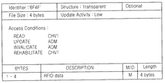
図6は、本発明の好ましい実施形態によってRFIDデータを保存するEFの構造を示す図である。 FIG. 6 is a diagram illustrating a structure of an EF for storing RFID data according to a preferred embodiment of the present invention.
EFは、GSM標準に準拠したものなので、既存SIMファイルシステムの拡張形態で具現されて、既存ソフトウェアの継続的な使用が保障される長所がある。 Since EF is compliant with the GSM standard, it is implemented in an extended form of the existing SIM file system, and has an advantage that continuous use of existing software is guaranteed.
識別子(Identifier)が可変できる範囲は、DFファイルIDにより決まっている。例えばDFRFIDが7F2XファイルIDを有する場合に、識別子(Identifier)は、6F2X、6F3X、6F4Xを有することができる。 The range in which the identifier can be changed is determined by the DF file ID. For example, when the DFRFID has a 7F2X file ID, the identifier can have 6F2X, 6F3X, and 6F4X.
構造(Structure)とは、EFのファイル構造を意味する。EFは、伝送(transparent)タイプ、線形固定(linear fixed)タイプ、サイクリック(cyclic)タイプに標準で定義されている。RFIDデータのようなバイトの列(sequence)形態は、伝送タイプが適当である。 “Structure” means an EF file structure. EF is defined as a standard in a transparent type, a linear fixed type, and a cyclic type. A transmission type is appropriate for a sequence form of bytes such as RFID data.
ファイルサイズ(file size)とは、保存されるRFIDデータサイズ(例:4バイト)を意味する。EFに保存されているRFIDデータを制御するソフトウェア命令語では、READ、UPDATE、INVALIDATE、REHABILITATEなどがあり、これは全部GSM標準に準拠したもので、各命令語が実行される条件ではCHV1、ADMなどがある。 The file size means a saved RFID data size (for example, 4 bytes). Software instruction words for controlling RFID data stored in the EF include READ, UPDATE, INVALIDATE, REHABILITATE, etc., all of which comply with the GSM standard. and so on.
CHV1(Card Holder Verification 1)は、使用者(card holder)のファイルアクセスが許可されたソフトウェアタスク(task)を表し、ADM(Administration)は、SIMカード運用者(administrator)のファイルアクセスが許可されたソフトウェアタスクを表す。 CHV1 (Card Holder Verification 1) represents a software task that allows the file access of the user (card holder), and ADM (Administration) allows the file access of the SIM card administrator (administrator). Represents a software task.
3) 動作手続き(Operational Procedure)
従来のSIMカードがRFID機能を提供することによって変わる動作手続きには、SIMカード自体のモード変化と、移動端末機とSIMカードとの間のインターフェース変化がある。
3) Operational Procedure
The operation procedure changed by providing the RFID function of the conventional SIM card includes a mode change of the SIM card itself and an interface change between the mobile terminal and the SIM card.
図7は、本発明の実施形態によるSIMカードのモード遷移状態を示す図である。 FIG. 7 is a diagram illustrating a mode transition state of the SIM card according to the embodiment of the present invention.
SIMカードは、移動端末機からのリセット要求に応じるATR(Answer-To-Reset)信号の送信以後に、特定モード(Specific Mode)と協議モード(Negotiable Mode)へ遷移することができる。 The SIM card can transition to a specific mode and a negotiable mode after transmitting an ATR (Answer-To-Reset) signal in response to a reset request from the mobile terminal.
特定モードは、通信専用モード(例:GSMモード)とRFID専用モードに区分され、協議モードは、移動端末機との信号交換を通じて移動端末機の応用ソフトウェア(Application Software)などで要求するモードである。移動端末機の要求によってスマートカードがRFIDモードに遷移されることも協議モードの一例である。 The specific mode is divided into a communication-only mode (eg, GSM mode) and an RFID-only mode, and the negotiation mode is a mode requested by application software (Application Software) of the mobile terminal through signal exchange with the mobile terminal. . An example of the consultation mode is that the smart card is switched to the RFID mode in response to a request from the mobile terminal.
モードの転換は、ISO/IEC7816−3に定義されているATR信号の特定モードバイト(Specific Mode byte)TA2により表示される。ATR信号は、移動端末機からのリセットについての応答(answer)として、SIMカードにより移動端末機側へ伝達されるバイトシーケンス(the sequence of bytes)であり、非動機方式(asynchronous character)である。 The mode change is indicated by a specific mode byte TA2 of the ATR signal defined in ISO / IEC7816-3. The ATR signal is a sequence of bytes transmitted to the mobile terminal side by the SIM card as a response (answer) to the reset from the mobile terminal, and is an asynchronous character.
図8は、本発明の好ましい実施形態によるSIMカードと移動端末機との間の信号交換状態を説明するための図である。 FIG. 8 is a diagram illustrating a signal exchange state between a SIM card and a mobile terminal according to a preferred embodiment of the present invention.
RFID機能を支援するSIMカードは、RFIDリーダー器の接近をSIMカードのCPUがインターラプト方式で認知した場合に、これを移動端末機のCPUにATR信号の形態で知らせるようになる。 The SIM card that supports the RFID function notifies the CPU of the mobile terminal in the form of an ATR signal when the CPU of the SIM card recognizes the approach of the RFID reader device by the interrupt method.
移動端末機SIMカードからRFID機能の動作を知らせるATR信号を受けるようになれば、移動端末機の応用プログラム或いは動作状態によって、これを許可(grant)してSIMカードがRFID機能を実行するようにする。 If the mobile terminal SIM card receives an ATR signal that informs the operation of the RFID function, the SIM card may execute the RFID function by granting it according to the application program or the operating state of the mobile terminal. To do.
また、移動端末機が、SIMカードの一次的機能、即ち、通信システムについての使用者認識(identification)などを優先要請する必要がある時やその他のRFID機能を実行することができない状況である時に拒絶(reject)することもできる。 Also, when the mobile terminal needs to make a primary request for the primary function of the SIM card, that is, user identification for the communication system, or when other RFID functions cannot be executed. It can also be rejected.
また、このような優先順位についての考慮なしに、SIMカードが、RFIDリーダー器の接近を感知すれば、すぐRFIDモードで使用されるように具現することもできる。 Further, the SIM card can be used in the RFID mode as soon as the proximity of the RFID reader is detected without considering the priority order.
図9は、図8に示されたATR信号の構造を示す図である。 FIG. 9 shows the structure of the ATR signal shown in FIG.
ISO/IEC7816−3に定義されているATR信号は、一列で伝送されるバイトの結合体である。各バイトは、ISO/IEC7816−3にその使用法が定義されており、使用が留保されているバイトもある。 The ATR signal defined in ISO / IEC 7816-3 is a combination of bytes transmitted in a row. The usage of each byte is defined in ISO / IEC7816-3, and some bytes are reserved for use.
したがって、これを用いて本発明の好ましい実施形態のように、SIMカードがRFID機能の開始を移動端末機に知らせるように具現することができる。 Therefore, the SIM card can be implemented to notify the mobile terminal of the start of the RFID function, as in the preferred embodiment of the present invention.
一例として、特定モードバイトTA2にRFIDモードであることを知らせるビット(例:下位4ビットの値‘1111’)を含むATR信号を作ることができる。 As an example, an ATR signal including a bit indicating that the RFID mode is in the specific mode byte TA2 (for example, a value “1111” of lower 4 bits) can be generated.
この特定モードバイトTA2は、コールドリセット(Cold Reset)以後に特定モードでRFIDモードで既に設定されていることを知らせる(現在RFIDモードであるSIMカードが移動端末機からRFIDと無関係な要求を受けた時に該当する。例えば、移動端末機が使用者IDを要求した場合に該当する)ことと、RFIDリーダー器の接近によるRFIDモードの開始を知らせる(通話モードからRFIDモードに切り替えるように知らせる状態)ことの、二つの用途で使用され得る。 This specific mode byte TA2 informs that the RFID mode has already been set in the specific mode after the cold reset (Cold Reset) (the SIM card which is currently in the RFID mode has received a request unrelated to the RFID from the mobile terminal) (For example, this applies when the mobile terminal requests a user ID) and informs the start of the RFID mode due to the approach of the RFID reader (a state in which it is notified to switch from the call mode to the RFID mode). Can be used in two applications.
他の例として、インターフェースバイト(Interface byte)であるTD(i)の下位4ビットにRFIDモードであることを知らせるビットを挿入することもできる。ISO/IEC7816−3標準では、TD(i)、TA(2)などの下位4ビットを係数(Parameter)Tで定義し、T=5〜3までは未来のために使用を留保している。したがって、このT値の中で一部をRFID用途で使えば、関連標準に反しないので、既存システムとの互換性が容易である。 As another example, a bit for notifying the RFID mode can be inserted into the lower 4 bits of TD (i) which is an interface byte. In the ISO / IEC 7816-3 standard, lower 4 bits such as TD (i) and TA (2) are defined by a coefficient (Parameter) T, and the use is reserved for the future from T = 5 to 3. Therefore, if a part of the T value is used for RFID, it does not violate related standards, and compatibility with existing systems is easy.
図10は、RFID部分を有するSIMカードが装着された移動端末機の構造を概略的に示す図である。 FIG. 10 is a diagram schematically illustrating a structure of a mobile terminal in which a SIM card having an RFID portion is mounted.
図面符号900は、移動端末機MEのプロセッサを示す。このプロセッサの具現例には、一名モバイルプロセッサと呼ばれるクォルコム(Qualcomm)社のMSM(Mobile Station Modem)チップ(chip)がある。
図面符号950は、SIMカードを示す。RFID部分を有するSIMカードが移動端末機に装着された時に、SIMカードが移動端末機に無線周波数識別モードへの転換を知らせることを説明するためのものである。ここでは、SIMカードのCPU912と、SIM部分914と、RFID部分916のみを示し、公知の構成要素は図示しない。
SIM部分914は、使用者情報を保存し、この使用者情報を含む使用者情報信号を発生させる使用者情報処理部である。また、使用者情報処理部は、使用者情報を保存する使用者情報メモリー部と、前記使用者情報信号を発生させるプログラムを含む使用者プログラムメモリー部と、を含む。
The
図3を参照して、その具現例について説明すると、使用者情報メモリー部は、EEPROM404に具現することができ、使用者プログラムメモリー部は、ROM410に具現することができる。
Referring to FIG. 3, the user information memory unit can be implemented in the
図4を参照して、その具現例について説明すると、使用者情報メモリー部は、EEPROM506に具現することができ、使用者プログラムメモリー部は、ROM504に具現することができる。
Referring to FIG. 4, the implementation example will be described. The user information memory unit can be implemented in the
前記RFID部分916は、無線周波数識別データを保存及び処理して無線周波数識別データを含む無線周波数識別信号を発生させる無線周波数識別情報処理部である。
The
また、無線周波数識別情報処理部は、無線周波数識別情報を保存する無線周波数識別情報メモリー部と、前記無線周波数識別信号を発生させる無線周波数識別機能部と、を含む。 The radio frequency identification information processing unit includes a radio frequency identification information memory unit that stores radio frequency identification information, and a radio frequency identification function unit that generates the radio frequency identification signal.
図3を参照して、その具現例について説明すると、無線周波数識別情報メモリー部は、EEPROM404或いはROM410に備えることができ、無線周波数識別機能部は、RFIDコデック部406と、RFID変調部408と、を含む。
Referring to FIG. 3, the implementation example will be described. The radio frequency identification information memory unit can be provided in the
図4を参照して、その具現例について説明すると、無線周波数識別情報メモリー部は、EEPROM506或いはROM504に備えることができ、無線周波数識別機能部は、RFIDコデック部508とRFID変調部510と、を含む。
Referring to FIG. 4, the implementation example will be described. The radio frequency identification information memory unit can be provided in the
CPU912は、前記使用者情報処理部と連結されて前記使用者情報信号を発生させるように命令し、前記使用者情報信号を送信し、前記無線周波数識別情報処理部と連結されて前記無線周波数識別信号を発生させるように命令し、前記無線周波数識別信号を送信する主演算部である。図3のCPU402と図4のCPU500に該当する。
The
RFIDリーダー器(図示せず)を移動端末機MEに一定距離以上接近させると、前記移動端末機MEに装着されたSIMカード950のRFID部分916でこれを感知する。RFID部分916は、この感知結果をSIMカード950のCPU912に伝達することにより、SIMカード950が無線周波数識別機能の実行の要請を受ける段階であることを認識させる。
When an RFID reader (not shown) approaches the mobile terminal ME over a certain distance, this is detected by the
このようになれば、SIMカード950のCPU912が、移動端末機のプロセッサ900に無線周波数識別モードへの転換を知らせる信号を伝送する。そして、前記SIMカード950は、無線周波数識別機能を実行するモードに転換する。
In this case, the
本発明は、既存RFIDタグと一緒にRFIDリーダー器から電源の供給を受けるか、コイル連結部がRFIDリーダー器から送信する搬送波信号(carrier wave signal)からクロックを抽出して機能ブロックに提供しないで、移動端末機の安定的な電源とクロックをRFID機能ブロックに供給するように具現することにより安定化をはかる。既存の供給方式は、RF環境などによって発生できる搬送波信号或いは誘導起電力の劣化などを通じて不安定になり得るからである。 The present invention does not receive power from an RFID reader together with an existing RFID tag, or extract a clock from a carrier wave signal transmitted from an RFID reader by a coil coupling unit and provide it to a functional block. The mobile terminal is stabilized by providing a stable power supply and clock to the RFID functional block. This is because the existing supply method can become unstable through a carrier wave signal that can be generated by an RF environment or the like, or by degradation of induced electromotive force.
以上、本発明を具体的な実施形態を参照して詳細に説明したが、本発明の範囲は前述の実施形態によって限定されるべきではなく、特許請求の範囲の記載及びこれと均等なものの範囲内で様々な変形が可能なことは、当該技術分野における通常の知識を持つ者には明らかである。 Although the present invention has been described in detail with reference to specific embodiments, the scope of the present invention should not be limited by the above-described embodiments, but the scope of the description of the claims and the equivalents thereof. It will be apparent to those skilled in the art that various modifications are possible.
201 クロック発生部(Clock Generator)
202 整流部(Rectifier)
203 変調制御部
204 行デコーダー(Row Decoder)
205 カウンター
206 メモリー
207 列デコーダー(Column Decoder)
209 変調回路
300 CPU
302 RAM
304 ROM
306 EEPROM
400 RAM
402 CPU
404 EEPROM
406 RFIDコデック部
408 RFID変調部
410 ROM
412 コイル連結部
414 インターラプト部
500 CPU500
502 RAM
504 ROM
506 EEPROM
508 RFIDコデック部
510 RFID変調部
514 コイル連結部
516 クロック変調部
518 RFIDクロック信号
520 SIMクロック信号
522 制御信号
900 移動端末機MEのプロセッサ
950 SIMカード
912 CPU
914 SIM部分
916 RFID部分
201 Clock Generator
202 Rectifier
203
205 Counter 206
209
302 RAM
304 ROM
306 EEPROM
400 RAM
402 CPU
404 EEPROM
406
412
502 RAM
504 ROM
506 EEPROM
508
914
Claims (20)
無線周波数識別データを保存し、前記無線周波数識別データを含む無線周波数識別信号を発生させる無線周波数識別情報処理部と、
前記使用者情報処理部と連結されて前記使用者情報信号の発生及び送信を制御し、前記無線周波数識別情報処理部と連結されて前記無線周波数識別信号の発生及び送信を命令する主演算部と、を含むことを特徴とするスマートカード。 A user information processing unit for storing user information and generating a user information signal including the user information;
A radio frequency identification information processing unit for storing radio frequency identification data and generating a radio frequency identification signal including the radio frequency identification data;
A main arithmetic unit connected to the user information processing unit to control generation and transmission of the user information signal, and connected to the radio frequency identification information processing unit to instruct generation and transmission of the radio frequency identification signal; The smart card characterized by including.
使用者情報を保存する使用者情報メモリー部と、
前記使用者情報信号を発生させるプログラムを含む使用者プログラムメモリー部と、を含むことを特徴とする請求項1記載のスマートカード。 The user information processing unit
A user information memory section for storing user information;
The smart card according to claim 1, further comprising: a user program memory unit including a program for generating the user information signal.
無線周波数識別情報を保存する無線周波数識別情報メモリー部と、
前記無線周波数識別信号を発生させる無線周波数識別機能部と、を含むことを特徴とする請求項1記載のスマートカード。 The radio frequency identification information processing unit
A radio frequency identification information memory unit for storing radio frequency identification information;
The smart card according to claim 1, further comprising a radio frequency identification function unit that generates the radio frequency identification signal.
前記無線周波数識別情報処理部は、無線周波数識別情報を保存する無線周波数識別情報メモリー部と、前記無線周波数識別信号を発生させる無線周波数識別機能部と、を含むことを特徴とする請求項1記載のスマートカード。 The user information processing unit includes a user information memory unit for storing user information, and a user program memory unit including a program for generating the user information signal,
The radio frequency identification information processing unit includes a radio frequency identification information memory unit that stores radio frequency identification information, and a radio frequency identification function unit that generates the radio frequency identification signal. Smart card.
無線周波数識別コデック部と、無線周波数識別変調部と、を含むことを特徴とする請求項3記載のスマートカード。 The radio frequency identification function unit
4. The smart card according to claim 3, further comprising a radio frequency identification codec unit and a radio frequency identification modulation unit.
前記スマートカードは、無線周波数識別タグを含み、
前記移動端末機のプロセッサは、前記スマートカードと通信して、前記スマートカードの無線周波数識別機能の実行を許可或いは拒絶することを特徴とする移動端末機。 A mobile terminal equipped with a smart card for storing user information,
The smart card includes a radio frequency identification tag;
The mobile terminal processor communicates with the smart card to permit or reject execution of the radio frequency identification function of the smart card.
前記無線周波数識別タグが、無線周波数識別リーダー器の接近を感知する第1過程と、
前記無線周波数識別リーダー器の接近を感知した無線周波数識別タグが、前記スマートカードの中央処理装置へ無線周波数識別機能の実行を要求する第2過程と、
前記スマートカードの中央処理装置が、前記移動端末機のプロセッサに無線周波数識別モードへの転換を知らせるモード転換信号を伝送する第3過程と、
前記信号を伝送した後に、前記スマートカードが、無線周波数識別機能を実行する第4過程と、からなることを特徴とする方法。 A method of executing a radio frequency identification function in a mobile terminal equipped with a smart card including a radio frequency identification tag,
A first process in which the radio frequency identification tag senses the approach of a radio frequency identification reader;
A second step in which a radio frequency identification tag that senses an approach of the radio frequency identification reader device requests the central processing unit of the smart card to perform a radio frequency identification function;
A third process in which the central processing unit of the smart card transmits a mode change signal informing the processor of the mobile terminal of the change to the radio frequency identification mode;
A method comprising: after transmitting the signal, the smart card performs a fourth step of performing a radio frequency identification function.
The method of claim 17, wherein the response signal includes information indicating rejection of execution of a radio frequency identification function.
Applications Claiming Priority (1)
| Application Number | Priority Date | Filing Date | Title |
|---|---|---|---|
| KR1020030085300A KR100566260B1 (en) | 2003-11-27 | 2003-11-27 | Mobile terminal integrated with a radio frequency identification transponder and smart card and radio frequency identification method thereof |
Publications (1)
| Publication Number | Publication Date |
|---|---|
| JP2005166047A true JP2005166047A (en) | 2005-06-23 |
Family
ID=34464765
Family Applications (1)
| Application Number | Title | Priority Date | Filing Date |
|---|---|---|---|
| JP2004338053A Pending JP2005166047A (en) | 2003-11-27 | 2004-11-22 | Mobile terminal with radio frequency identification tag and smart card combined, and radio identification method by mobile terminal |
Country Status (5)
| Country | Link |
|---|---|
| US (1) | US7374100B2 (en) |
| EP (1) | EP1536573B1 (en) |
| JP (1) | JP2005166047A (en) |
| KR (1) | KR100566260B1 (en) |
| CN (1) | CN100342393C (en) |
Cited By (4)
| Publication number | Priority date | Publication date | Assignee | Title |
|---|---|---|---|---|
| US7757943B2 (en) | 2006-08-29 | 2010-07-20 | Metavante Corporation | Combined payment/access-control instrument |
| KR101178514B1 (en) * | 2010-08-27 | 2012-08-30 | 한국광성전자 주식회사 | Radio communication interface system and method |
| KR101372153B1 (en) * | 2007-06-04 | 2014-03-10 | 엘지이노텍 주식회사 | Smart card |
| KR101382940B1 (en) * | 2007-08-14 | 2014-04-08 | 엘지이노텍 주식회사 | Smart card |
Families Citing this family (53)
| Publication number | Priority date | Publication date | Assignee | Title |
|---|---|---|---|---|
| WO2004114239A2 (en) * | 2003-06-13 | 2004-12-29 | Wildseed Ltd. | Emulated radio frequency identification |
| WO2005093644A1 (en) | 2004-03-19 | 2005-10-06 | Nokia Corporation | Detector logic and radio identification device and method for enhancing terminal operations |
| KR101051703B1 (en) * | 2004-08-09 | 2011-07-25 | 삼성전자주식회사 | Integrated circuit card and integrated circuit card system with suspend / reset function |
| US7356539B2 (en) | 2005-04-04 | 2008-04-08 | Research In Motion Limited | Policy proxy |
| US8198985B2 (en) | 2005-05-31 | 2012-06-12 | Amtech Systems, LLC | Automatic mode detection in a dual operating mode RFID tag |
| NO324406B1 (en) * | 2005-06-20 | 2007-10-08 | Telenor Asa | SIM RFID reader with WLAN access |
| KR101246343B1 (en) * | 2005-09-06 | 2013-03-21 | 엘지전자 주식회사 | A Mobile Phone Equipped with RFID Tag and Thereof Method for Controlling Access of RFID Reader |
| CN100527159C (en) * | 2005-10-31 | 2009-08-12 | 深圳华为通信技术有限公司 | Storage card and terminal equipment combining storage card |
| JP5175215B2 (en) * | 2005-12-30 | 2013-04-03 | ノキア コーポレイション | Method and device for emulating multiple RFID tags in a single portable electronic device |
| KR100756179B1 (en) * | 2006-01-09 | 2007-09-05 | 주식회사 팬택 | A mobile communication terminal having a active rfid transponer |
| KR100738923B1 (en) * | 2006-04-24 | 2007-07-12 | 에스케이 텔레콤주식회사 | Smart card having zigbee module in financial settlement module or subscriber identification module and mobile communication terminal having same |
| US7966263B2 (en) * | 2006-05-04 | 2011-06-21 | First Data Corporation | Wireless phone RF presentation instrument with sensor control |
| US9466057B2 (en) * | 2006-05-04 | 2016-10-11 | First Data Corporation | RF presentation instrument with sensor control |
| KR100889562B1 (en) * | 2006-05-10 | 2009-03-23 | 한국전자통신연구원 | System with Shared Power Amplifier for Mobile Communication Terminal with Mobile RFID Function |
| US7690579B2 (en) * | 2006-07-13 | 2010-04-06 | Research In Motion Limited | Answer to reset (ATR) pushing |
| KR100912076B1 (en) | 2006-07-26 | 2009-08-12 | 한국전자통신연구원 | Apparatus and method for Integrated Reader and Tag |
| US20080090595A1 (en) * | 2006-10-11 | 2008-04-17 | Sony Ericsson Mobile Communications Ab | Near field communication for profile change in switching network acess |
| US7667574B2 (en) * | 2006-12-14 | 2010-02-23 | Corning Cable Systems, Llc | Signal-processing systems and methods for RFID-tag signals |
| FR2912591B1 (en) * | 2007-02-12 | 2009-05-01 | Oberthur Card Syst Sa | METHOD AND DEVICE FOR CONTROLLING THE EXECUTION OF AT LEAST ONE FUNCTION IN A SHORT-RANGE WIRELESS COMMUNICATION MODULE OF A MOBILE DEVICE. |
| KR100823678B1 (en) * | 2007-02-12 | 2008-04-18 | 주식회사 와이즈캐치 | Contactless information processor |
| DE102007039226A1 (en) | 2007-08-20 | 2009-02-26 | Giesecke & Devrient Gmbh | Real-time measurement on a portable data carrier |
| US8157178B2 (en) | 2007-10-19 | 2012-04-17 | First Data Corporation | Manufacturing system to produce contactless devices with switches |
| KR101418249B1 (en) * | 2007-11-20 | 2014-07-11 | 삼성전자주식회사 | Terminal having RF ID function and method for processing information using the same |
| US8831220B2 (en) * | 2007-11-30 | 2014-09-09 | Battelle Energy Alliance, Llc | Processing module operating methods, processing modules, and communications systems |
| SK50042008A3 (en) | 2008-01-04 | 2009-09-07 | Logomotion, S. R. O. | Method and system for authentication preferably at payments, identifier of identity and/or agreement |
| DE102008013664A1 (en) * | 2008-03-11 | 2009-09-24 | T-Mobile International Ag | Arrangement and method for operating a SIM card |
| SK288721B6 (en) * | 2008-03-25 | 2020-01-07 | Smk Kk | Method, circuit and carrier for perform multiple operations on the keypad of mobile communication equipment |
| US20090287589A1 (en) * | 2008-05-16 | 2009-11-19 | Fivel Steven E | Mobile, compact communication device including rfid |
| CA2732235C (en) * | 2008-08-29 | 2017-03-28 | Logomotion, S.R.O. | Removable card for a contactless communication, its utilization and the method of production |
| KR101479655B1 (en) * | 2008-09-12 | 2015-01-06 | 삼성전자주식회사 | Method and system for security of portable terminal |
| SK288757B6 (en) * | 2008-09-19 | 2020-05-04 | Smk Kk | System and method for contactless payment authorization |
| US9098845B2 (en) * | 2008-09-19 | 2015-08-04 | Logomotion, S.R.O. | Process of selling in electronic shop accessible from the mobile communication device |
| SK288747B6 (en) * | 2009-04-24 | 2020-04-02 | Smk Kk | Method and system for cashless payment transactions, particularly with contactless payment device using |
| SK50862008A3 (en) * | 2008-09-19 | 2010-06-07 | Logomotion, S. R. O. | System for electronic payment applications and method for payment authorization |
| CN101685491B (en) * | 2008-09-27 | 2011-08-24 | 佛山市顺德区汉达精密电子科技有限公司 | Portable electronic equipment and mobile RFID reader |
| SK288641B6 (en) * | 2008-10-15 | 2019-02-04 | Smk Corporation | Communication method with POS terminal and frequency convertor for POS terminal |
| US8269609B2 (en) * | 2008-12-11 | 2012-09-18 | At&T Intellectual Property I, Lp | Devices, systems and methods for portable device location |
| CN101765242A (en) * | 2008-12-25 | 2010-06-30 | 深圳富泰宏精密工业有限公司 | User identification card and connector thereof as well as portable communication device provided with connector |
| SK500092009A3 (en) * | 2009-02-27 | 2010-09-07 | Logomotion, S. R. O. | Computer mouse for data transmission, preferably at electronic payment, method for data transmission |
| KR101555637B1 (en) * | 2009-03-27 | 2015-09-24 | 삼성전자주식회사 | Smart card |
| KR101789113B1 (en) * | 2009-05-03 | 2017-10-23 | 에스에무케이 가부시키가이샤 | A payment terminal using a mobile communication device, such as a mobile phone;a method of direct debit payment transaction |
| SK288521B6 (en) | 2009-07-08 | 2017-12-04 | Smk Corporation | Method and system for entering the PIN code at non-cash payments, carrier PIN code |
| US20110063091A1 (en) * | 2009-09-11 | 2011-03-17 | Hynix Semiconductor Inc. | Radio frequency identification system |
| EP2317337A1 (en) * | 2009-11-03 | 2011-05-04 | Gemalto SA | Contactless transfer system for personal data |
| CN101847090B (en) * | 2010-02-05 | 2014-11-12 | 广州市花都区中山大学国光电子与通信研究院 | Special microcontroller for RFID (Radio Frequency Identification) intelligent card |
| EP2383955B1 (en) * | 2010-04-29 | 2019-10-30 | BlackBerry Limited | Assignment and distribution of access credentials to mobile communication devices |
| US20130241701A1 (en) * | 2010-09-13 | 2013-09-19 | Trident Rfid Pty Ltd | System and method for updating parameters and firmware on rfid readers |
| US8532619B2 (en) * | 2010-12-30 | 2013-09-10 | Samsung Electronics Co., Ltd. | System for authorizing the use of communication devices by proximity |
| JP2013105280A (en) * | 2011-11-11 | 2013-05-30 | Dainippon Printing Co Ltd | Ic card and computer program for ic card |
| CN102724642B (en) * | 2012-06-12 | 2015-02-25 | 中国联合网络通信集团有限公司 | Service message processing method, smart card and terminal equipment |
| US9996871B2 (en) | 2014-10-15 | 2018-06-12 | Toshiba Global Commerce Solutions Holdings Corporation | Systems, methods, and mobile computing devices for purchase of items and delivery to a location within a predetermined communication range |
| CN104504413B (en) * | 2014-11-19 | 2018-01-02 | 上海大学 | A kind of RFID antenna deployment system monitored in real time for warehouse and method |
| FR3035252B1 (en) | 2015-04-14 | 2017-04-28 | Stmicroelectronics Rousset | METHOD FOR MANAGING INFORMATION COMMUNICATION BETWEEN AN NFC CONTROLLER AND A SECURE ELEMENT IN AN APPARATUS, AND CORRESPONDING NFC APPARATUS AND CONTROLLER |
Family Cites Families (27)
| Publication number | Priority date | Publication date | Assignee | Title |
|---|---|---|---|---|
| US4075632A (en) | 1974-08-27 | 1978-02-21 | The United States Of America As Represented By The United States Department Of Energy | Interrogation, and detection system |
| US4360810A (en) | 1981-01-19 | 1982-11-23 | The United States Of America As Represented By The United States Department Of Energy | Multichannel homodyne receiver |
| US4786907A (en) | 1986-07-14 | 1988-11-22 | Amtech Corporation | Transponder useful in a system for identifying objects |
| US4739328A (en) | 1986-07-14 | 1988-04-19 | Amtech Corporation | System for identifying particular objects |
| US4782345A (en) | 1986-07-29 | 1988-11-01 | Amtech Corporation | Transponder antenna |
| US4835377A (en) | 1987-06-10 | 1989-05-30 | Brown Richard R | Programmer for identification system |
| US4816839A (en) | 1987-12-18 | 1989-03-28 | Amtech Corporation | Transponder antenna |
| US4853705A (en) | 1988-05-11 | 1989-08-01 | Amtech Technology Corporation | Beam powered antenna |
| US5394439A (en) * | 1991-11-12 | 1995-02-28 | Comsat Corporation | Bisdn compatible modem codec for digital information communication system |
| US5640002A (en) * | 1995-08-15 | 1997-06-17 | Ruppert; Jonathan Paul | Portable RF ID tag and barcode reader |
| US5943624A (en) | 1996-07-15 | 1999-08-24 | Motorola, Inc. | Contactless smartcard for use in cellular telephone |
| JPH1051349A (en) * | 1996-08-01 | 1998-02-20 | Nec Corp | Portable communication equipment |
| US5991749A (en) * | 1996-09-11 | 1999-11-23 | Morrill, Jr.; Paul H. | Wireless telephony for collecting tolls, conducting financial transactions, and authorizing other activities |
| US20040016796A1 (en) * | 1998-11-25 | 2004-01-29 | Diebold, Incorporated | Automated banking apparatus and method |
| TW460846B (en) * | 1998-12-10 | 2001-10-21 | Toshiba Corp | Data recording media having certification information |
| US6369712B2 (en) * | 1999-05-17 | 2002-04-09 | The Goodyear Tire & Rubber Company | Response adjustable temperature sensor for transponder |
| US6704774B2 (en) * | 1999-09-17 | 2004-03-09 | Gilbarco Inc. | Content preference system at retail outlet |
| US6775632B1 (en) * | 1999-12-14 | 2004-08-10 | The Goodyear Tire & Rubber Company | Calibration of a transponders for a tire pressure monitoring system |
| US20020002534A1 (en) * | 2000-06-27 | 2002-01-03 | Davis Terry L. | Method and system for managing transactions |
| JP2002149948A (en) * | 2000-11-15 | 2002-05-24 | Matsushita Electric Ind Co Ltd | Marketing system and advertisement medium used in the same |
| KR100736601B1 (en) | 2000-11-24 | 2007-07-09 | 엘지전자 주식회사 | Washing machine and control method of the same |
| JP2002247157A (en) | 2001-02-15 | 2002-08-30 | Toppan Forms Co Ltd | Portable telephone set, tag for use in the portable telephone set, and how to use the portable telephone set |
| US7236742B2 (en) * | 2001-06-18 | 2007-06-26 | Brigham Young University | System and method for wireless data transfer for a mobile unit |
| JP2003016398A (en) | 2001-06-27 | 2003-01-17 | Sony Corp | Portable terminal machine |
| JP3960070B2 (en) * | 2002-02-14 | 2007-08-15 | 凸版印刷株式会社 | INFORMATION PROVIDING SYSTEM, INFORMATION PROVIDING METHOD, AND PROGRAM RECORDING THE METHOD |
| CA2427369A1 (en) * | 2002-12-24 | 2004-06-24 | Research In Motion Limited | Methods and apparatus for controlling power to electrical circuitry of a wireless communication device having a subscriber identity module (sim) interface |
| KR100584328B1 (en) | 2003-10-07 | 2006-05-26 | 삼성전자주식회사 | Mobile Terminal Circuit Integrated With A Radio Frequency Identification Transponder And Radio Frequency Identification Method Thereof |
-
2003
- 2003-11-27 KR KR1020030085300A patent/KR100566260B1/en not_active IP Right Cessation
-
2004
- 2004-10-21 US US10/970,102 patent/US7374100B2/en active Active
- 2004-11-22 JP JP2004338053A patent/JP2005166047A/en active Pending
- 2004-11-23 EP EP04027779A patent/EP1536573B1/en not_active Expired - Fee Related
- 2004-11-26 CN CNB2004100963528A patent/CN100342393C/en not_active Expired - Fee Related
Cited By (4)
| Publication number | Priority date | Publication date | Assignee | Title |
|---|---|---|---|---|
| US7757943B2 (en) | 2006-08-29 | 2010-07-20 | Metavante Corporation | Combined payment/access-control instrument |
| KR101372153B1 (en) * | 2007-06-04 | 2014-03-10 | 엘지이노텍 주식회사 | Smart card |
| KR101382940B1 (en) * | 2007-08-14 | 2014-04-08 | 엘지이노텍 주식회사 | Smart card |
| KR101178514B1 (en) * | 2010-08-27 | 2012-08-30 | 한국광성전자 주식회사 | Radio communication interface system and method |
Also Published As
| Publication number | Publication date |
|---|---|
| CN1627321A (en) | 2005-06-15 |
| EP1536573A2 (en) | 2005-06-01 |
| EP1536573B1 (en) | 2011-05-11 |
| US20050116050A1 (en) | 2005-06-02 |
| US7374100B2 (en) | 2008-05-20 |
| KR20050051508A (en) | 2005-06-01 |
| CN100342393C (en) | 2007-10-10 |
| KR100566260B1 (en) | 2006-03-29 |
| EP1536573A3 (en) | 2007-08-22 |
Similar Documents
| Publication | Publication Date | Title |
|---|---|---|
| JP2005166047A (en) | Mobile terminal with radio frequency identification tag and smart card combined, and radio identification method by mobile terminal | |
| EP1522955B1 (en) | Mobile terminal circuit including an RFID tag and wireless identification method using the same | |
| EP1528768A2 (en) | Mobile communication terminal with RFID function and RFID programming method in the same | |
| JP5123857B2 (en) | NFC reader with passive mode of operation with low power consumption | |
| CN100388297C (en) | Wireless communication device providing a contactless interface for a smart card reader | |
| US8186591B2 (en) | Contactless management between a smart card and mobile terminal | |
| EP1783660A2 (en) | Memory card and terminal equipment incorporating the same | |
| US20090235037A1 (en) | Method and device for customizing a portable electronic entity | |
| US9014757B2 (en) | System for communicating in a contact-less manner, and corresponding removable chip card, terminal and method | |
| EP3617931B1 (en) | Communication device and method | |
| WO2010133469A1 (en) | Device for conventional smart card allowing an electronic transaction through a network | |
| US10790880B2 (en) | Method of operating an NFC device, the NFC device, and a communication system | |
| WO2009017292A1 (en) | Mobile status detection contactless module | |
| KR101156155B1 (en) | smart card having zigbee communication function and mobile terminal using it and data processing method thereof | |
| KR100926364B1 (en) | Method and Apparatus for Providing Simultaneously Plural Application Interfaces in Smart Card | |
| KR20060027589A (en) | Combi-smart card system capable of changing data on magnetic stripe and multiple membership card service method using the same | |
| KR20090050749A (en) | Communication module and method for smart card application service using it |
Legal Events
| Date | Code | Title | Description |
|---|---|---|---|
| A977 | Report on retrieval |
Free format text: JAPANESE INTERMEDIATE CODE: A971007 Effective date: 20070724 |
|
| A131 | Notification of reasons for refusal |
Free format text: JAPANESE INTERMEDIATE CODE: A131 Effective date: 20070814 |
|
| A521 | Request for written amendment filed |
Free format text: JAPANESE INTERMEDIATE CODE: A523 Effective date: 20071113 |
|
| A02 | Decision of refusal |
Free format text: JAPANESE INTERMEDIATE CODE: A02 Effective date: 20080122 |
|
| A521 | Request for written amendment filed |
Free format text: JAPANESE INTERMEDIATE CODE: A523 Effective date: 20080421 |
|
| A911 | Transfer to examiner for re-examination before appeal (zenchi) |
Free format text: JAPANESE INTERMEDIATE CODE: A911 Effective date: 20080528 |
|
| A912 | Re-examination (zenchi) completed and case transferred to appeal board |
Free format text: JAPANESE INTERMEDIATE CODE: A912 Effective date: 20080620 |