JP2005149671A - Optical disk device and standby method of the same - Google Patents
Optical disk device and standby method of the same Download PDFInfo
- Publication number
- JP2005149671A JP2005149671A JP2003389497A JP2003389497A JP2005149671A JP 2005149671 A JP2005149671 A JP 2005149671A JP 2003389497 A JP2003389497 A JP 2003389497A JP 2003389497 A JP2003389497 A JP 2003389497A JP 2005149671 A JP2005149671 A JP 2005149671A
- Authority
- JP
- Japan
- Prior art keywords
- area
- optical
- recording
- standby position
- optical disk
- Prior art date
- Legal status (The legal status is an assumption and is not a legal conclusion. Google has not performed a legal analysis and makes no representation as to the accuracy of the status listed.)
- Pending
Links
Images


Abstract
Description
本発明は、光ディスクの記録・再生処理の終了後に、未記録領域の手前に光学ヘッドを待機させる光ディスク装置及び光ディスク装置の待機方法に関する。 The present invention relates to an optical disk apparatus that waits an optical head before an unrecorded area after completion of recording / reproducing processing of the optical disk, and a standby method of the optical disk apparatus.
最近、DVD(Digital Versatile Disc)等の光ディスク装置が開発され普及してきており、動作信頼性や使い勝手等に、更なる付加価値が求められている。この一例として、特開平10−79126号公報に記載されている光ディスク装置においては、片面に複数層の情報記録面が存在する光ディスクを再生する際に、光ディスクがOTPかPTPかを判断し、再生時に一時停止命令を受けたとき、内周又は外周へ1トラックジャンプして待機するものである。 Recently, optical disc apparatuses such as DVDs (Digital Versatile Discs) have been developed and become widespread, and further added value is required for operational reliability and usability. As an example of this, in the optical disc apparatus described in Japanese Patent Laid-Open No. 10-79126, when an optical disc having a plurality of information recording surfaces on one side is reproduced, it is determined whether the optical disc is OTP or PTP, and reproduction is performed. Sometimes, when a pause command is received, one track jumps to the inner or outer circumference and waits.
この公報に記載された光ディスク装置は、再生光ディスクに限定した処理を行っており、1トラックジャンプによって比較的安定したサーボ状態を保持することができる。 The optical disk device described in this publication performs processing limited to a reproduction optical disk, and can maintain a relatively stable servo state by one track jump.
しかし、記録型の光ディスクでは、記録領域と未記録領域で記録層の反射率が異なるため、記録領域と未記録領域の境界でサーボ状態を保持することは、サーボ信号のレベルが変動する領域でサーボをかけることになり、極めて不安定な状態であるといえる。又、境界領域から記録を開始する際に、必要な情報、例えばエラー訂正コードなどの必要な情報を記録開始アドレスでの適切に生成するために、最長で2トラック以上手前のトラックへ戻って、情報を再生してから記録が行われる必要がでてくる。
すなわち、上述した従来の光ディスク装置は再生専用であり、光ディスク記録装置特有の課題を解決することができない。これは、情報記録層における未記録の領域と記録済み領域とでは、光ディスクの特性によって反射率が異なるためである。光ディスクの特性としては、DVD−RAMなどのように、データ記録することによって反射率が上がる(Low-to-High)特性と、記録によって反射率が下がる(High-to-Low)特性の2種類の特性があるが、この反射率の変化は2倍ないし3倍以上となることが一般的で、記録領域と未記録領域の境界領域では、各種信号がこの反射率の変化の影響を受けることになる。 That is, the above-described conventional optical disk apparatus is dedicated for reproduction, and cannot solve the problems peculiar to the optical disk recording apparatus. This is because the reflectance varies depending on the characteristics of the optical disc between the unrecorded area and the recorded area in the information recording layer. There are two types of optical disc characteristics, such as the characteristic that the reflectivity increases by recording data (Low-to-High) and the characteristic that the reflectivity decreases by recording (High-to-Low), such as DVD-RAM. However, this change in reflectivity is generally 2 to 3 times or more, and various signals are affected by the change in reflectivity in the boundary area between the recording area and the unrecorded area. become.
この結果、記録領域と未記録領域の境界領域で精密なサーボを行うことが難しくなり、従来の再生型光ディスクで行われていたように、再生終了領域から1トラック戻った位置で待機していると、待機のトラックホールド状態で未記録領域と記録領域の両方の領域にトラック位置決めされる可能性がある。従って、特に記録処理の場合は、次の命令を待機している間、サーボ動作を安定して維持することができないという問題がある。 As a result, it becomes difficult to perform precise servoing at the boundary area between the recording area and the unrecorded area, and the apparatus is waiting at a position one track back from the reproduction end area, as is done in the conventional reproduction type optical disc. Then, there is a possibility that the track is positioned in both the unrecorded area and the recorded area in the standby track hold state. Therefore, particularly in the case of recording processing, there is a problem that the servo operation cannot be stably maintained while waiting for the next command.
更に、記録型の光ディスクの場合、情報の記録・再生を行うためには、記録・再生要求が発生してから記録・再生処理を開始するまでの応答時間が高速であることが求められるが、従来装置では、光学ヘッドが未記録領域で待機しているわけではないので、記録命令を受けても直ちに記録処理を行うことができないという問題がある。 Further, in the case of a recordable optical disc, in order to record / reproduce information, it is required that a response time from when a record / reproduction request is generated to when recording / reproduction processing is started is high-speed, In the conventional apparatus, since the optical head is not waiting in the unrecorded area, there is a problem that the recording process cannot be performed immediately even if a recording command is received.
更に記録処理の場合は、前に記録されたデータの中に埋め込まれたエラー訂正コードを読取った上で生成されることがある。この動作をスムーズに実現するためには、読取るべ
きエラー訂正コードが記録された位置において待機しておくのが最適の方法であり、従来のように1トラック戻っておくだけでは、必ずしもエラー訂正コードを迅速に読み出すことができないという問題がある。
Further, in the case of a recording process, it may be generated after reading an error correction code embedded in previously recorded data. In order to realize this operation smoothly, it is optimal to stand by at the position where the error correction code to be read is recorded, and the error correction code is not necessarily required only by returning one track as in the prior art. Cannot be read quickly.
この発明は、記録型光ディスクの記録(再生)処理終了後に光学ヘッドを最適位置で待機させることで、次の命令に応じて安定した動作で記録(再生)処理を行うことができる光ディスク装置及び光ディスク装置の待機方法を提供することを目的とする。 The present invention provides an optical disc apparatus and an optical disc that can perform recording (reproduction) processing with stable operation in accordance with the next command by waiting the optical head at an optimal position after completion of recording (reproduction) processing of the recordable optical disc. It is an object of the present invention to provide a device standby method.
上記した課題を解決するために、この発明は、情報記録層を有する光ディスクに対してレーザ光を照射し又は反射波を受光して記録処理又は再生処理を行う光学ヘッドと、前記記録処理又は再生処理が終了した後に、前記光ディスクの各領域の物理特性を検出しこれに応じて、前記光学ヘッドの待機位置を決定する待機位置決定手段と、前記待機位置決定手段によって決定された前記待機位置に応じて、前記光学ヘッドを移動させて待機するべく前記光学ヘッドの位置を制御する制御手段と、前記制御手段によって制御された前記光学ヘッドの待機位置の前記光ディスクの回転数を、前記記録処理又は再生処理が終了した位置での前記光ディスクの回転数と同一の回転数に制御する回転制御手段とを具備することを特徴とする。 In order to solve the above-described problems, the present invention provides an optical head for performing recording processing or reproducing processing by irradiating an optical disc having an information recording layer with laser light or receiving reflected waves, and the recording processing or reproducing processing. After the process is completed, the physical characteristics of each area of the optical disc are detected, and the standby position determination means for determining the standby position of the optical head according to the detected physical characteristics, and the standby position determined by the standby position determination means In response, the control means for controlling the position of the optical head to wait by moving the optical head, and the rotation speed of the optical disk at the standby position of the optical head controlled by the control means, And a rotation control means for controlling the number of revolutions of the optical disc to be the same as the number of revolutions of the optical disc at the position where the reproduction process is completed.
以上詳述したように本発明によれば、未記録領域と記録領域の境界領域の影響を受けることがなく安定なサーボ動作が実現できると同時に、残った未記録領域Mを記録に使用することができ、更に、記録要求が与えられた時、そのままトラックトレースすることにより既に記録された情報を用いて次に記録するために必要な情報を再生することができるので迅速な記録動作の開始を可能とする光ディスク装置及び光ディスク装置の待機方法を提供することができる。 As described above in detail, according to the present invention, a stable servo operation can be realized without being affected by the boundary area between the unrecorded area and the recorded area, and the remaining unrecorded area M can be used for recording. In addition, when a recording request is given, it is possible to reproduce information necessary for the next recording by using the already recorded information by performing track tracing as it is, so that a quick recording operation can be started. An optical disc device and a standby method for the optical disc device can be provided.
以下、図面を参照しながら本発明に係る光ディスク装置及び光ディスク装置の待機方法について詳細に説明する。 Hereinafter, an optical disk device and a standby method of the optical disk device according to the present invention will be described in detail with reference to the drawings.
<本発明に係る光ディスク装置>
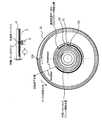
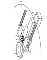
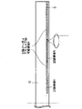
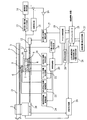
本発明の第1実施形態に係る光ディスク装置の構成について説明する。図1は、本発明の第1実施形態に係る光ディスク装置の一例を示すブロック図、図2は、本発明の第1実施形態に係る光ディスクの一例を示すブロック図、図3は、光ディスク装置の光学ヘッド等の配置を示す構成図、図4は、光ディスク装置の光学ヘッドの構成図である。ここでは、図2に示すような片面に2層の情報記録層を有し、各々の情報記録層の情報トラックが内周から外周へ連続記録が可能なシングルスパイラルのグルーブ構造101が設けられた光ディスクに記録処理を施す光ディスク装置について説明を行う。
<Optical Disc Device According to the Present Invention>
The configuration of the optical disc apparatus according to the first embodiment of the present invention will be described. FIG. 1 is a block diagram showing an example of an optical disc apparatus according to the first embodiment of the present invention, FIG. 2 is a block diagram showing an example of an optical disc according to the first embodiment of the present invention, and FIG. FIG. 4 is a configuration diagram showing the arrangement of the optical head and the like, and FIG. 4 is a configuration diagram of the optical head of the optical disc apparatus. Here, a single
本発明の第1実施形態に係る光ディスク装置が処理の対象とする光ディスクDは、図2に示すように、情報記録層として相変化記録層を備えた書き換え型の媒体であり、本発明に係る光ディスク装置が有する対物レンズ5によって集光される光ビームで、情報の記録・再生が行われる第1の記録層3と第2の記録層4を有する記録媒体である。光ディスクDは、光ディスク装置が有するスピンドルモータ2に取り付けられたエンコーダ28の出力もしくは光ディスクDからの再生信号により回転速度を検出し、回転数が所望の回転数となるようにスピンドルモータ回転制御回路29によって回転制御がされる。特に情報記録が行われる際には、回転線速を一定に保つZCLV(Zoned Constant Linear Velocity)方式などが採用され、記録が行われるトラックが所属するZone内では一定の回転数となるように回転制御が行われる。
An optical disc D to be processed by the optical disc apparatus according to the first embodiment of the present invention is a rewritable medium having a phase change recording layer as an information recording layer, as shown in FIG. This is a recording medium having a
更に、光学ヘッド10は、所定の波長のレーザ光を光ディスクの所定の情報記録層に照射することにより、記録(マーク形成)を行う。この記録は、例えば記録マークのエッジに情報を持たせたマーク長記録方式により行われる。光学ヘッド10に設けられたレーザ光源から出射されたレーザ光は、コリメートされて平行光となった後、図示しない光学素子を介して光学補正機構8に入射される。この光学補正機構8では、例えば情報記録層に形成される光学スポットが球面収差をもたないようにリレーレンズや液晶素子によって収差の補正を行う。この光学収差補正機構8で補正された光ビームは、更に立上げミラー7を介して対物レンズ5に入射され、光ディスクDの所定の情報記録面に光学スポットを形成する。一方、情報記録面で反射された光ビームは、再び立上げミラー7を介して、その一部が光検出器9に入射される。この光検出器9は、複数に分割された検出セルの光電変換により、情報記録面に集光された光学スポットの目標位置に対する位置誤差の検出を行う。この位置誤差としては、情報記録面に対して焦点のあった光学スポットを形成するためのフォーカス位置誤差、その他トラック位置誤差、傾き誤差、球面収差誤差がある。
Further, the
情報記録面には、情報記録・再生を行うための情報トラックが形成されており、この目標トラックに対する光ディスク半径方向の位置ずれがトラック位置誤差である。傾き誤差は、対物レンズ5によって照射される光ビームの光軸と光ディスクDの法線とのずれ角で、この角度が大きいと光学スポットにコマ収差が発生し、スポット品位が下がることになる。最後に球面収差は、同じく光学スポットのスポット品位を劣化させる収差で、対物レンズ5によって集光される波面が球面からずれることによって発生する。
An information track for recording / reproducing information is formed on the information recording surface, and a positional deviation in the optical disc radial direction with respect to the target track is a track position error. The tilt error is a deviation angle between the optical axis of the light beam irradiated by the
光ディスク装置では、上記の各種位置誤差を、光検出器9と差分回路11などを用い位置決め誤差検出回路19によって検出し、適正な光学スポットが形成されるように補償制御器20によってそれぞれの位置決め誤差に対応する制御操作量を算出し、光学補正機構制御回路21、フォーカス機構制御回路22、精位置決め機構制御回路23、粗位置決め機構制御回路17、傾き調整機構制御回路24にそれぞれ制御操作量を入力する。各制御回路では、入力された制御操作量に基づき、光学スポットが目標位置に適正に形成されるように光学補正機構8、対物レンズ位置決め機構6、粗位置決め機構12を駆動制御する。更に、差分回路11からの出力が相対変位算出器13と速度検出部15とに与えられ、基準速度発生回路14と速度検出器15との出力が演算され、増幅器16を経由して、粗位置決め機構制御回路17に供給され、この出力が粗位置決め機構12を駆動制御している。
In the optical disk apparatus, the above-described various position errors are detected by the positioning
このような光学ヘッド10の駆動系の構成以外にも、光ディスク装置は、図示しない記録処理系、再生処理系、制御系の構成を有している。すなわち、光学ヘッド10に接続される再生処理系の回路であるデータ再生回路や、記録処理系の回路であり光学ヘッド10に内蔵される半導体レーザダイオードの発光を制御するレーザ制御回路、更にこれらの動作を司る制御部の構成であるCPUや記憶領域であるRAMやROM、そして、外部装置とのデータ通信を行うインタフェース回路等を有している。
In addition to the configuration of the drive system of the
更に、図3に、本発明の第1実施形態の光ディスク装置の装置構成の一例が示され、図4に本発明の光ディスク装置の光学ヘッド10の詳細な光学系の構成が示される。これらの図において、レーザ光源28から出射したレーザ光がリレーレンズを用いた光学補正機構8によって光学的に調整される。更に、誤差信号検出系へ光ディスクDからの戻り光を走光するために、ハーフプリズム29が用いられている。
Further, FIG. 3 shows an example of the apparatus configuration of the optical disk apparatus according to the first embodiment of the present invention, and FIG. 4 shows the detailed optical system configuration of the
<第1実施形態>
第1実施形態は、一層又は複数層の記録層を有する光ディスクに対する光ディスク装置において、記録又は再生処理の終了後に、光学ヘッドを未記録領域の所定量だけ手前の位
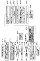
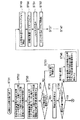
置に待機させる光ディスク装置及び光ディスク装置の待機方法を提供するものである。図5乃至図9は、光ディスク装置の光学ヘッドの待機位置の各例を示す図、図10及び図11、図17は、光ディスク装置のレイヤージャンプを含む光学ヘッドの待機処理を説明するためのフローチャートである。
<First Embodiment>
In the optical disk apparatus for an optical disk having one or more recording layers, the optical disk apparatus and the optical disk apparatus make the optical head stand by a predetermined amount in the unrecorded area before the end of the recording or reproducing process. A standby method is provided. FIGS. 5 to 9 are diagrams showing examples of the standby position of the optical head of the optical disk apparatus, and FIGS. 10, 11 and 17 are flowcharts for explaining the standby process of the optical head including the layer jump of the optical disk apparatus. It is.
(本発明の光学ヘッドの待機方法の原理)
本発明は、情報記録層を有する記録用の光ディスクでは記録領域Rと未記録領域Mとは反射率が大きく異なるため、記録領域Rと未記録領域Mとの境界付近で光学ヘッドを待機させるとサーボが不安定となりやすいため、例えば、2トラックかそれ以上の距離をおいて、記録領域R側に光学ヘッドを待機することで動作安定性を確保しながら迅速な記録処理も同時に可能とするものである。
(Principle of optical head standby method of the present invention)
In the present invention, in the recording optical disk having the information recording layer, the recording area R and the non-recording area M have greatly different reflectances. Therefore, when the optical head is made to stand by near the boundary between the recording area R and the non-recording area M, Since the servo tends to become unstable, for example, it is possible to simultaneously perform rapid recording processing while ensuring operational stability by waiting for the optical head on the recording area R side at a distance of 2 tracks or more. It is.
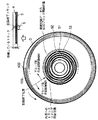
記録用の光ディスクは、図6に示すように、記録領域Rである既に記録済みで記録不可能な領域、未記録領域Mである記録されておらず記録が可能な領域、記録可能領域Kである記録が一度は行われたが削除処理されており記録が可能な領域に少なくとも分類することができる。本発明に係る待機方法では、未記録領域Mが存在せず記録可能領域Kが存在すれば、記録可能領域Kの手前で光学ヘッドを待機させるものである。 As shown in FIG. 6, the optical disk for recording has a recording area R that is already recorded and cannot be recorded, an unrecorded area M that is not recorded and can be recorded, and a recordable area K. A certain recording has been performed once, but it has been deleted and can be classified into at least a recordable area. In the standby method according to the present invention, if the unrecorded area M does not exist and the recordable area K exists, the optical head is made to wait before the recordable area K.
しかし、図7に示すように複数の未記録領域Mが存在する場合や、図8や図9に示すように複数の記録可能領域Kが存在する場合等があり、その場合の待機位置を決定する際の優先順位を以下に示す。 However, there are a case where a plurality of unrecorded areas M exist as shown in FIG. 7 and a case where a plurality of recordable areas K exist as shown in FIGS. 8 and 9, and the standby position in that case is determined. The order of priority when doing this is shown below.
(待機位置の優先順位)
待機位置の優先順位を図面を用いて以下に示すが、この優先順位は限定的なものではなく自由に選択することができるものである。しかし、使用状況に応じた一定の優先順位を定めておき、図1の待機位置決定回路27により待機位置が決定される。
(Priority of standby position)
The priorities of the standby positions are shown below with reference to the drawings, but the priorities are not limited and can be freely selected. However, a predetermined priority order is determined according to the use situation, and the standby position is determined by the standby
図5は基本的な記録用の光ディスクDの一例を示しており、一つの未記録領域Mの例えば2トラック手前の位置に、待機位置が決定されている。この例では、基本的な待機位置が示されている。 FIG. 5 shows an example of a basic optical disk D for recording. A standby position is determined at a position, for example, two tracks before one unrecorded area M. In this example, a basic standby position is shown.
図6は複数の記録層を有する記録用の光ディスクDの一例を示しており、未記録領域Mが存在する第2の記録層4の未記録領域Mの例えば2トラック手前の位置に、待機位置が決定されている。記録が終了した記録層3に未記録領域Mがなく他の層にあれば、レイヤージャンプを行い、未記録領域Mの手前を待機位置とする。
FIG. 6 shows an example of a recording optical disk D having a plurality of recording layers. The standby position is, for example, two tracks before the unrecorded area M of the
図7は複数の記録層を有する記録用の光ディスクDの一例を示しており、各層に未記録領域Mが存在するが、光学ヘッド10側の第1の記録層3の未記録領域Mの例えば2トラック手前の位置に、待機位置が決定されている。原則として光学ヘッド10側の層の未記録領域Mが優先される。しかし、光学ヘッド10の反対側の層の未記録領域Mが選ばれるという優先順位も可能である。
FIG. 7 shows an example of a recording optical disk D having a plurality of recording layers. Each layer has an unrecorded area M. For example, an unrecorded area M of the
図8は一つの記録層を有する記録用の光ディスクDの一例を示しており、未記録領域Mが存在せず、記録可能領域Kが複数存在する。ここでは、記憶容量が大きい右側の記録可能領域Kの手前の位置に、待機位置が決定されている。原則として記憶容量が大きい方の記録可能領域Kが選ばれるが、記録可能領域Kの位置に応じて決定されるという優先順位も可能である。 FIG. 8 shows an example of a recording optical disk D having one recording layer, in which an unrecorded area M does not exist and a plurality of recordable areas K exist. Here, a standby position is determined at a position before the recordable area K on the right side having a large storage capacity. In principle, the recordable area K having the larger storage capacity is selected, but a priority order that is determined according to the position of the recordable area K is also possible.
図9は複数の記録層を有する記録用の光ディスクDの一例を示しており、未記録領域Mが存在せず、記録可能領域Kが各層に存在する。ここでは、記憶容量が大きい第2の記録
層4の記録可能領域Kの手前の位置に、待機位置が決定されている。原則として記憶容量が大きい方の記録可能領域Kが選ばれるが、記録可能領域Kの位置に応じて、光学ヘッド側の層の記録可能領域Kに決定されるという優先順位も可能である。
FIG. 9 shows an example of a recording optical disk D having a plurality of recording layers, where an unrecorded area M does not exist and a recordable area K exists in each layer. Here, the standby position is determined at a position before the recordable area K of the
以上のように、一つの優先順位として、未記録領域Mを記録可能領域Kに優先する、複数の未記録領域Mが存在すれば光学ヘッド側の層の未記録領域Mさらに記録開始位置に近い方の未記録領域Mを優先する、複数の記録可能領域Kのみなら大きな記憶容量をもつ記録可能領域Kを優先する、という設定が可能である。 As described above, as one priority, the unrecorded area M is given priority over the recordable area K. If there are a plurality of unrecorded areas M, the unrecorded area M of the layer on the optical head side is further closer to the recording start position. It is possible to set such that priority is given to the unrecorded area M, and if only a plurality of recordable areas K is given, the recordable area K having a large storage capacity is given priority.
(処理フローチャート)
次に、上述した優先順位に応じて行われる本発明に係る待機方法の具体的な例をフローチャートを用いて詳細に説明する。
(Processing flowchart)
Next, a specific example of the standby method according to the present invention performed according to the above-described priority order will be described in detail using a flowchart.
上記したように、目標位置に光学スポットが形成されて一連の情報の記録が行われるが、記録又は再生動作が終了したとき、待機動作に入って、新たに一連の情報の記録又は再生命令がシステムコントローラ25に来るまで待機する。この待機処理のシーケンスについて、図10及び図11のフローチャートを用いて説明する。
As described above, an optical spot is formed at the target position and a series of information is recorded, but when the recording or reproducing operation is completed, a standby operation is started and a new series of information recording or reproducing command is issued. Wait until the
まず情報の記録又は再生を行った後の待機方法の第1実施形態について図10を参照しながら述べる。初めに情報の記録又は再生を行って、システムコントローラ25で情報記録又は再生動作が終了したと判断した場合(ST11)、記録情報管理部26により現在光学スポットを形成している情報記録層の記録可能領域Kと未記録領域Mの容量を算出する(ST12)。又、同時に、現在光学スポットを形成していない情報記録層の記録可能領域と未記録領域の容量も算出しておく(ST13)。
First, a first embodiment of a standby method after recording or reproducing information will be described with reference to FIG. When information is recorded or reproduced first, and the
(未記録領域と記録可能領域とを識別する方法)
ここで、未記録領域Mと記録可能領域Kとを識別する方法として、以下のパターンが考えられる。ここで、パターン2a、2bはマクロな視点でパターン3を捉えている。
パターン1
未記録領域 :結晶状態または非晶状態が一様である領域
記録領域 :結晶状態及び非晶状態が混在分布した領域
パターン2a
未記録領域 :反射率が低い領域
記録領域 :反射率が高い領域
パターン2b
未記録領域 :反射率が高い領域
記録領域 :反射率が低い領域
パターン3
未記録領域 :反射率が一様である領域
記録領域 :反射率が異なる領域が混在分布した領域であり、上記反射率が一様である領域より平均的な反射率が高い、または低い領域
パターン4
未記録領域 :色素が一様に分布し反射率が一様である領域
記録領域 :一部の色素膜が変化し反射率が異なる状態が混在分布した領域
パターン5
未記録領域 :光学スポットの反射面が平坦一様である領域
記録領域 :上記平坦部が変形した凹凸を有する領域
未記録領域と記録領域との識別について、上述したようなパターンが考えられる。光学ヘッド10の検出結果に応じて記録情報管理部26は、特に、反射率の高さ、更に反射率の分布の程度を、一定の閾値と比較することにより、未記録領域Mと記録領域Kとを識別す
ることができる。
(Method for identifying unrecorded area and recordable area)
Here, as a method for discriminating between the unrecorded area M and the recordable area K, the following patterns can be considered. Here, the patterns 2a and 2b capture the
Pattern 1
Unrecorded area: Area in which crystalline state or amorphous state is uniform Recording area: Area pattern 2a in which crystalline state and amorphous state are mixedly distributed
Unrecorded area: Area with low reflectance Recording area: Area pattern 2b with high reflectance
Unrecorded area: Area with high reflectivity Record area:
Unrecorded area: Area where the reflectance is uniform Recording area: Area where the areas where the reflectances are different are mixedly distributed, and an area pattern whose average reflectance is higher or lower than the area where the reflectance is uniform 4
Unrecorded area: Area in which the dye is uniformly distributed and the reflectance is uniform Recording area:
Unrecorded area: Area where the reflecting surface of the optical spot is flat and uniform Recording area: Area having unevenness where the flat part is deformed The pattern as described above can be considered for discriminating between an unrecorded area and a recorded area. In accordance with the detection result of the
これらの結果をもとに、待機位置判断回路27では、先の優先順位に応じて、未記録領域Mへ移動できるかどうかを判断する(ST14)。すなわち、記録層にそれぞれ移動できる未記録領域Mが存在するかどうかが判断され、未記録領域Mが存在しなければ、記録可能領域Kが存在するかどうかが判断される。ここで、未記録領域Mも記録可能領域Kも存在しなければ、現在位置で待機することとなる(ST27)。
Based on these results, the standby
移動できる未記録領域M又は記録可能領域Kが存在すれば、その移動先のアドレスを特定する(ST15)。現在光学スポットを形成している情報記録層が第1情報記録層3であり、第1情報記録層3に未記録領域Mが存在するかどうかを判断する(ST16)。存在していると判断した場合、記録が終了したアドレスに相当する未記録領域Mと記録領域Rの境界領域から一定のトラック分、一例として2トラックかそれ以上だけ、記録済み領域側にあるトラックを目指してジャンプ動作を行う。以下、この動作を退避動作と呼ぶ。又、ここで、未記録領域Mが存在せず、記録可能領域Kだけであれば、記録可能領域の手前にアクセスするものである(ST17)。
If there is an unrecorded area M or recordable area K that can be moved, the destination address is specified (ST15). It is determined whether or not the information recording layer that currently forms the optical spot is the first
ジャンプが終了し、記録終了トラックより2トラック手前の所定のアドレスに到達したことを確認した後、光学スポットは光ディスクDの回転ごとに1トラックジャンプすることによってそのトラックにホールドされて待機状態になる(ST18)。 After confirming that the jump is completed and a predetermined address two tracks before the recording end track has been reached, the optical spot is held by that track by jumping one track for each rotation of the optical disc D, and enters a standby state. (ST18).
この時の所定トラックは、プッシュプル法やDPP法によって検出されるトラック位置決め誤差信号が、前記記録領域と未記録領域の境界領域の影響を受けないように決定されることが望ましく、短くは2トラックが適当な値となる。又、このトラックへホールドするためのジャンプ動作は、図2に示したように記録終了位置に略相当する1トラック内周のアドレス位置で開始される。このように少なくとも2トラック分の退避動作を行っておけば、記録領域Rと未記録領域Mの境界領域に存在するサーボ信号レベル変化の悪影響を回避することができ、安定な待機動作を実現することが可能となる。 The predetermined track at this time is preferably determined so that the track positioning error signal detected by the push-pull method or the DPP method is not affected by the boundary area between the recording area and the unrecorded area. The track is an appropriate value. Further, the jump operation for holding to the track is started at an address position on the inner circumference of one track substantially corresponding to the recording end position as shown in FIG. By performing the evacuation operation for at least two tracks in this way, the adverse effect of the servo signal level change existing in the boundary area between the recording area R and the unrecorded area M can be avoided, and a stable standby operation is realized. It becomes possible.
又、上記した記録動作が終了した位置に、領域のロスなく記録を行う要求がシステムコントローラ25に与えられたときも、情報の記録に必要で、記録開始領域以前の領域に既に記録された情報をスムースに再生することが可能となり、情報記録動作を開始する前に余計な動作を発生させずに高速な記録動作を実現することが可能となる。
Also, when a request for recording without loss of area is given to the
なおここで、未記録領域Mに記録する動作終了後の場合は、記録終了位置が境界トラックとなるので、ステップST17のステップ動作のアクセス動作は、第1の所定トラック数分手前のトラックにジャンプして戻ることで実現されることになる(ST18)。 In this case, after the end of the operation of recording in the unrecorded area M, the recording end position becomes the boundary track, so the access operation of the step operation of step ST17 jumps to the track before the first predetermined number of tracks. Then, it is realized by returning (ST18).
又、ステップST16において、現在光学スポットを形成している情報記録層が第1の情報記録層3であり、第1の情報記録層には未記録領域Mが存在しておらず、第2の情報記録層4に未記録領域Mが存在していると判断した場合(ST16)、レイヤージャンプを行うものである。すなわち、下記のように待機位置決定回路27によって決定された所定の第2の情報記録層のアドレスへのアクセス動作を行う。まず、第2の情報記録層の未記録領域と記録領域の境界領域に相当する現在の情報記録層の略アドレスを記録情報管理部26から検知する(ST19)。このとき、偏心や2つの情報記録層貼り合せの軸ずれの影響を回避するため、上記略アドレスは境界領域に相当するアドレス(図6のA点に対応)に対して約0.1mm程度内周側のアドレス(図6のB'点)として与えられる。続いて、このアドレスに対して第1の情報記録層内でのアクセス動作(ST20)が行われ、目標アドレスに到達後に、第2の情報記録層の所定のアドレス(B点)へレイヤージャンプが行われる(ST21)。その後、フォーカス引込み動作やおよび諸サーボ動作の調整、
トラック引込み動作が行われて(ST22)、到達した第2の情報記録層のアドレスを読取る(ST23)。そして、第2の情報記録層4の未記録領域Mの境界となるトラックから所定トラック数分手前のトラックへアクセス動作が実行される。又は、記録可能領域Kの手前へと、アクセス動作が実行される(ST24)。次に、トラック引込みを行い(ST25)、トラックホールド動作によってアクセスが終了し、図6が示すように待機状態に入る(ST26)。
In step ST16, the information recording layer that currently forms the optical spot is the first
A track pull-in operation is performed (ST22), and the address of the reached second information recording layer is read (ST23). Then, an access operation is performed from the track that is the boundary of the unrecorded area M of the second
以上のレイヤージャンプの動作は、現在光学スポットを形成している情報記録層が第2の情報記録層4であり、第1の情報記録層3に未記録領域Mが存在していると判断した場合(ST16)、第1の情報記録層3の境界領域へアクセスする場合にも、同様に行われ図7が示すような位置で待機状態に入ることとなる。
In the above-described layer jump operation, it is determined that the information recording layer that currently forms the optical spot is the second
又、一方、図9に示すように、第1の情報記録層3にも第2の情報記録層4にも未記録領域Mが存在しないと判断した場合(ST14)、待機位置決定回路27ではこの2つの情報記録層の記録可能容量を比較して、容量が大きいと判断した情報記録層を待機状態の層として選択して、別の層又は現在の層の最も大きい記録可能領域Kの境界領域へアクセスする。図9では、第2の情報記録層4の記録可能領域Kへと光学ヘッドが移動されている。
On the other hand, as shown in FIG. 9, when it is determined that there is no unrecorded area M in the first
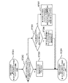
ここで、ステップST17あるいはステップST24に示される待機位置へのアクセス時のスピンドルモータの回転制御について、図17を用いて解説する。まず待機のために指定される所定トラック手前のトラックへのアクセスが開始されると(ST201)、待機位置として指定される所定トラック手前の位置が所属するZoneが、ステップST17では記録が終了したアドレスに相当する未記録領域Mとの境界領域の所属するZoneと異なるか否か、ステップST24では第2の情報記録層4の未記録領域Mの境界となるトラックから所定トラック数分手前のトラックが所属するZoneと異なるか否かが判断される(ST202)。ここで、待機位置として指定されたトラックが所属するZoneと同一のZoneである場合は、スピンドルモータの回転数は変更されずにトラックジャンプなどのアクセス制御が実行され(ST203)、待機位置への移動が完了する(ST204)。しかし、ステップST202で、待機位置のZoneと異なることがわかった場合、境界領域の所属するZoneの最内周のトラック位置で待機することでトラッキングが不安定にならずにすむかどうかが検討される(ST205)。これはすなわち、境界領域の所属するZoneの最内周のトラックを待機位置とすることで、トラッキングが安定となるかどうかを判断することであり、前記所定のトラックの本数を減らしても安定となるか、移動するトラック本数から判断することになる。待機する予定のトラックのZoneと記録終了したトラックのZoneが異なる場合、こうした状況が発生する。この判断の結果、同一Zone内の最内周のトラックへの移動でも、待機のためのトラックの移動本数として十分であると判断されると、スピンドルモータの回転数は変化せずに同一Zone内の最内周のトラックへのアクセスが実行される(ST206)。一方、同一Zone内の最内周のトラックへのアクセスでは、トラッキングを安定に行うために戻るトラック数として不十分であると判断された場合、予定の所定トラック数分手前のトラックへのアクセスを行う。ここで一般的にはZoneに応じて回転数が制御されるため、到達したZoneで指定される回転数での制御が行われるが、回転数を変更してしまうと境界領域へ再度戻る場合に、再び回転数を変更しなければならない。このため、スピンドルモータの回転数は、境界領域の回転数のまま所定のトラック数分手前のトラックへのアクセスを行い(ST207)、待機位置への移動が完了する(ST204)。
Here, the rotation control of the spindle motor at the time of accessing the standby position shown in step ST17 or step ST24 will be described with reference to FIG. First, when access to the track before the predetermined track designated for standby is started (ST201), the zone to which the position before the predetermined track designated as the standby position belongs is the address at which recording was completed in step ST17. In step ST24, a track that is a predetermined number of tracks before the track that is the boundary of the unrecorded area M of the second
以上のような手順により、本発明に係る光学ヘッドの待機方法が行われるものであり、記録処理又は再生処理が終了すると、光学ヘッドが未記録領域M又は記録可能領域Kの手前で待機することにより、確実で安定した記録処理が可能となる。 The optical head standby method according to the present invention is performed by the procedure as described above. When the recording process or the reproduction process is completed, the optical head waits before the unrecorded area M or the recordable area K. Thus, a reliable and stable recording process can be performed.
(光ディスク起動時)
本発明の第1実施形態の待機方法のシーケンスは、光ディスクDの起動時、すなわち、光ディスクDが挿入されて光ディスクの認識が行われた後に(ST10)、図11が示すように行うことも可能である。ここで、ステップST27では、光学ヘッドの移動ができないときは、光ディスクの初期位置での待機が行われる。又、図5及び図8に示すように、光ディスクDが第1の情報記録層3しか有さない場合でも、上記した図10及び図11のフローチャートに沿って同様に図に示す位置で待機することができる。
(When the optical disc starts)
The sequence of the standby method according to the first embodiment of the present invention can be performed as shown in FIG. 11 when the optical disk D is started, that is, after the optical disk D is inserted and the optical disk is recognized (ST10). It is. Here, in step ST27, when the optical head cannot be moved, standby at the initial position of the optical disk is performed. Further, as shown in FIGS. 5 and 8, even when the optical disc D has only the first
(省電力モード)
又、省電力モードとして、待機状態が一定の時間以上継続し、システムコントローラ25へ記録又は再生の要求が来ないときは、光学スポットは更に記録領域側へ第2の所定トラック数だけ移動し、各種のサーボ状態をホールド又は開ループとして、フォーカスサーボのみかけた状態に保持する省電力状態に移行する。この第2の所定トラックは、トラック位置決めサーボが開ループとなってサーボがかからない状態となっても、光ディスクの偏心などの影響で光学スポットが前記境界領域に形成されることがないように決定されるべきで、偏心量が学習などの方法によって測定されているときは、この値から第2の所定トラック数が決定される。又、偏心量が測定できない場合は、一例として、0.1mm程度の値となることが好適である。
(Power saving mode)
In the power saving mode, when the standby state continues for a certain period of time and no request for recording or reproduction is received from the
このように第2の所定のトラック数分の退避動作を行っていないと、省電力状態を解除して再びサーボ状態に入るときに、未記録領域にサーボしてしまう可能性がある。上述のように、未記録領域Mと記録領域Rとでは、情報記録層の反射率が異なり、サーボ用の信号のレベルが大きく異なることが予想される。結果的に、サーボ状態が不安定になる可能性があり、安定かつ高速に省電力状態から復帰するには対策が必要がある。この対策として上記したように第2の所定トラック数を設定し、省電力状態に入ることで、待機状態にあったシステムコントローラ25に情報の記録又は再生要求が来ても、瞬時に安定なサーボ状態に入ることが可能となる。
As described above, if the save operation for the second predetermined number of tracks is not performed, there is a possibility that when the power saving state is canceled and the servo state is entered again, the servo is performed in the unrecorded area. As described above, the reflectance of the information recording layer is different between the unrecorded area M and the recorded area R, and the level of the servo signal is expected to be greatly different. As a result, there is a possibility that the servo state becomes unstable, and it is necessary to take measures to recover from the power saving state stably and at high speed. As a countermeasure against this, by setting the second predetermined number of tracks as described above and entering the power saving state, even if an information recording or reproduction request is received from the
またこのように第2の所定のトラック数分の退避動作を行う際にも、図17に示したスピンドルモータの制御方法のように、スピンドルモータの回転数は変更されずに退避を行うことで、時間を要するスピンドルモータの回転数変更の手間を省き、省電力モードからの復帰時間を短くすることが可能である。 Also, when performing the retraction operation for the second predetermined number of tracks in this way, the retraction operation is performed without changing the rotation speed of the spindle motor as in the spindle motor control method shown in FIG. Thus, it is possible to save time and effort for changing the rotational speed of the spindle motor, and to shorten the return time from the power saving mode.
なお、上記した1度目の未記録領域Mからの回避である第1の所定トラック数は、初めから第2の所定トラック数と同一となるように、やや大きめの値に設定することも可能である。 Note that the first predetermined number of tracks, which is the avoidance from the first unrecorded area M, can be set to a slightly larger value so as to be the same as the second predetermined number of tracks from the beginning. is there.
(その他)
なお、記録可能領域Kでは、情報の未記録領域は存在しないので、サーボ用の信号が未記録領域と記録領域の境界の悪影響を受けることはないが、記録動作の要求が来たときにスムースにエラー訂正コードなどの次の記録動作のために必要な情報を読取るために、上記の退避動作によって、第1の所定のトラック数分、最終記録が終了したトラックから戻る退避動作を行っておくことが望ましい。又、この場合は、省電力状態を想定して、第2の所定トラック数分更に退避する動作は行わなくても、サーボ状態は安定に復帰できるため、第2の所定トラック数分の退避動作は行わなくても構わない。
(Other)
In the recordable area K, since there is no unrecorded area of information, the servo signal is not adversely affected by the boundary between the unrecorded area and the recorded area. However, when the recording operation is requested, it is smooth. In order to read information necessary for the next recording operation, such as an error correction code, the evacuation operation for returning from the track where the final recording has been completed is performed by the above-described evacuation operation for the first predetermined number of tracks. It is desirable. Further, in this case, assuming that the power saving state is assumed, the servo state can be stably recovered without performing further retreat operation for the second predetermined number of tracks. Is not necessary.
記録可能領域の残存容量によって、残存容量が所定の値以下、例えば1ECCブロックに相当する32KB以下となったときは、記録動作は行えないと待機位置決定回路27で判断して、再生動作に備えるため必ず第1の情報記録層へ戻るようにしてもよい。
When the remaining capacity falls below a predetermined value due to the remaining capacity of the recordable area, for example, 32 KB or less corresponding to one ECC block, the standby
なお、上記した未記録領域Mは、欠損(defect)などの影響であえて記録しなかった領域は含めないものとし、又、所定の容量未満の領域も含めないものである。又、仮想データを埋める要求で仮想的なデータが埋められている場合は、仮想データ記録済み領域は、未記録領域M又は記録可能領域Kとして扱うことができる。 Note that the above-mentioned unrecorded area M does not include an area that is not recorded due to the influence of a defect or the like, and does not include an area less than a predetermined capacity. When virtual data is filled with a request to fill virtual data, the virtual data recorded area can be handled as an unrecorded area M or a recordable area K.
又、情報の再生動作の終了を受けて待機動作に入るとき、この終了が一時停止命令などによって発生した場合は、上記した境界領域へアクセスせずに、終了時のトラックに対してトラックホールド動作を行うことができる。 Also, when entering the standby operation after the completion of the information reproduction operation, if this termination occurs due to a pause command or the like, the track hold operation is performed on the track at the end without accessing the boundary area described above. It can be performed.
又、情報の再生動作の終了を受けて待機動作に入るとき、一定期間が経過するまでは、再生動作が再開される可能性を加味して現在位置に待機するものとし、一定期間が経過すると、再生動作の再開がないとして、上述した未記録領域M又は記録可能領域Kへの光学ヘッドの移動を行うという動作モードを新たに設定することも可能である。このような動作モードを設けることで、記録した光ディスクの再生処理の操作性をよくすることが可能となる。 In addition, when entering the standby operation after the completion of the information reproduction operation, it waits at the current position in consideration of the possibility that the reproduction operation is resumed until a certain period elapses. It is also possible to newly set an operation mode in which the optical head is moved to the unrecorded area M or the recordable area K described above, assuming that the reproduction operation is not resumed. By providing such an operation mode, it becomes possible to improve the operability of the reproduction processing of the recorded optical disk.
以上、本発明に係る第1実施形態の待機方法によれば、光学ヘッドを未記録領域M又は記録可能領域Kの手前で待機させることで、安定したサーボで待機させることができ、しかも記録処理の迅速な再開を可能とする光ディスク装置及び光ディスク装置の待機方法を提供するものである。 As described above, according to the standby method of the first embodiment according to the present invention, the optical head is allowed to wait in front of the unrecorded area M or the recordable area K, so that it is possible to wait with stable servo and recording processing. It is possible to provide an optical disc apparatus and a standby method for the optical disc apparatus that enable quick restart of the optical disc apparatus.
なお、本発明の待機方法は、未記録領域に連続的に記録を行った後の待機方法、2つの情報記録層のどちらにも未記録領域が存在する場合に記録動作が終了した後の待機方法、一度は情報記録が行われた情報記録層に記録を行った後の待機方法、情報の再生動作後の待機方法が少なくとも含まれている。 Note that the standby method of the present invention is a standby method after continuous recording in an unrecorded area, and a standby after the recording operation is completed when an unrecorded area exists in both of the two information recording layers. It includes at least a method, a standby method after recording on an information recording layer where information has been recorded once, and a standby method after an information reproducing operation.
なお上述した第1実施形態には、片面に1層又は2層の情報記録層を有する場合について述べたが、3層以上の情報記録層を有する場合でも同様の作用効果をもって待機方法を規定することができる。 In the above-described first embodiment, the case of having one or two information recording layers on one side has been described. However, even in the case of having three or more information recording layers, the standby method is defined with the same function and effect. be able to.
又、情報の記録又は再生中に、強制的に一時停止命令がシステムコントローラに与えられた場合でも、上記の待機方法における退避動作を行うことで、一時停止命令が解除された後の動作をより安定かつ高速に行うことが可能となる。 Even when a temporary stop command is forcibly given to the system controller during recording or reproduction of information, the operation after the temporary stop command is canceled can be performed by performing the save operation in the above standby method. It becomes possible to perform it stably and at high speed.
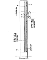
<第2実施形態>
第2実施形態は、第1実施形態で特定した光ディスク装置において、光学ディスクが未記録領域又は記録可能領域に対して待機する位置は、内周から外周へ記録されるトラック構造の場合には、未記録領域又は記録可能領域の内周側、外周から内周へ記録される場合のトラック構造の場合には、未記録領域又は記録可能領域の外周側に設定される光ディスク装置と光ディスク装置の待機方法を提供するものである。図12は、本発明に係る第2実施形態である光ディスク装置の光学ヘッドの待機位置の一例を示す図である。
Second Embodiment
In the optical disk device specified in the first embodiment, the second embodiment is a track structure in which the optical disk is waiting for an unrecorded area or a recordable area when the track structure is recorded from the inner periphery to the outer periphery. In the case of a track structure in which recording is performed from the inner circumference side of the unrecorded area or the recordable area, from the outer circumference to the inner circumference, the optical disc apparatus set on the outer circumference side of the unrecorded area or the recordable area and the standby of the optical disc apparatus A method is provided. FIG. 12 is a diagram showing an example of the standby position of the optical head of the optical disc apparatus according to the second embodiment of the present invention.
ここで、図12に示す光ディスクDは片面に2層の情報記録層を有し、トラック構造がグルーブ構造となっており、第1の情報記録層3は内周から外周へ記録するようなトラック構造であり、第2の情報記録層4は外周から内周へ情報記録するトラック構造となっている光ディスクを対象としている。
Here, the optical disc D shown in FIG. 12 has two information recording layers on one side, the track structure is a groove structure, and the first
このようなディスク構造の光ディスクに記録再生を行う光ディスク装置において、光ディスク装置の構造は、第1実施形態の場合と同様であるので、説明を省略する。又、この
光ディスク装置における待機方法も、図10及び図11に示した第1実施形態の待機方法のシーケンスと同様となる。
In the optical disk apparatus that records and reproduces data on the optical disk having such a disk structure, the structure of the optical disk apparatus is the same as that in the first embodiment, and thus the description thereof is omitted. Also, the standby method in this optical disc apparatus is the same as the sequence of the standby method of the first embodiment shown in FIGS.
第1実施形態との相違点としては、第2の情報記録層4のトラック構造が、外周から内周へ記録可能な構造となっているため、待機すべき対象のトラックにトラックホールドする際のトラックジャンプ方法が、所定のジャンプ開始位置から外周方向へジャンプして、外周方向の位置で待機する点である。又、このとき、偏心や2つの情報記録層貼り合せの軸ずれの影響を回避するための、上記略アドレスは、境界領域に相当するアドレス(図12のA点)に対して、約0.1mm程度外周側のアドレス(図12のB'点)が与えられ、このアドレスに対して第1の情報記録層3内でステップST20に示されるようなアクセス動作が行われることとなる。
The difference from the first embodiment is that the track structure of the second
目標アドレスに到達後には、第1実施形態と同様に、ステップST21に示されるように第2の情報記録層4の所定のアドレス(図12のB点)へレイヤージャンプが行われる。図12に示すように、第2実施形態においては、第2の情報記録層4に未記録領域Mが存在する場合、図10に示した判断手順に従って、光学スポットが未記録領域Mの外周方向へ例えば2トラック分又は2トラック以上だけ離れた位置において待機するものである。
After reaching the target address, as in the first embodiment, a layer jump is performed to a predetermined address (point B in FIG. 12) of the second
なお、この場合スピンドルモータの回転制御の方法は図17のステップST205とステップST206は、記録トラックの構造に応じて、Zone内の最内周ではなく最外周のトラックへのアクセスと読み替えて行われる。 In this case, the spindle motor rotation control method is performed by replacing steps ST205 and ST206 in FIG. 17 with access to the outermost track, not the innermost track in the zone, according to the structure of the recording track. .
このように、第2実施形態では、光ディスクDにおいて記録される方向に対応して、トラックジャンプする方向及び光学ヘッドが待機する位置が決定されることを特定するものである。 As described above, in the second embodiment, it is specified that the track jumping direction and the optical head standby position are determined in correspondence with the recording direction on the optical disc D.
<第3実施形態>
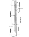
第3実施形態は、第1実施形態で特定した光ディスク装置において、複数の未記録領域が存在する際の待機位置として優先されるべき領域を、グルーブとランドとに記録領域をもつトラック構造の場合において特定した光ディスク装置と光ディスク装置の待機方法を提供するものである。図13は、本発明に係る第3実施形態である光ディスク装置の光学ヘッドの待機位置の一例を示す図、図14及び図15は、第3実施形態の待機方法の一例を説明するためのフローチャート、図16は、第3実施形態に係る光ディスク装置の一例を示すブロック図である。
<Third Embodiment>
In the optical disk apparatus specified in the first embodiment, the third embodiment has a track structure in which a priority area as a standby position when a plurality of unrecorded areas exist is a track structure having recording areas in grooves and lands. The optical disk apparatus specified in the above and a standby method of the optical disk apparatus are provided. FIG. 13 is a diagram showing an example of the standby position of the optical head of the optical disc apparatus according to the third embodiment of the present invention, and FIGS. 14 and 15 are flowcharts for explaining an example of the standby method of the third embodiment. FIG. 16 is a block diagram showing an example of an optical disc apparatus according to the third embodiment.
第3実施形態において対象とする光ディスクDは、図12に示すものであり、グルーブとランドとに記録領域をもつトラック構造を有している。更に、第3実施形態に係る光ディスク装置は、図1の第1実施形態に係る光ディスク装置とほぼ同等の構造をもっているが、グルーブとランドとを切り替えるための極性切り換え回路28を更に有しており、システムコントローラ25の制御下において、補償制御器20と位置決め誤差検出回路19とに制御信号を供給して、極性を切り替える点が第1実施形態の光ディスク装置とは異なる。
The target optical disk D in the third embodiment is as shown in FIG. 12, and has a track structure having recording areas in grooves and lands. Further, the optical disk apparatus according to the third embodiment has a structure substantially equivalent to that of the optical disk apparatus according to the first embodiment of FIG. 1, but further includes a
第3実施形態に係る光ディスクは、図13に示すように、一般にはグルーブ部102が先に記録され、次にランド部103への記録が行われることが多い。この場合、待機方法のシーケンスは図14のフローチャートに示すようなものとなる。
In the optical disc according to the third embodiment, as shown in FIG. 13, generally, the
以下、図14のフローチャートを用いて第3実施形態の待機方法を詳細に説明する。光ディスクのトラック構造におけるグルーブ部とランド部は、この場合二つの異なる情報記
録領域であると考えることができる。このように考えると、図14のシーケンスでは、情報の記録又は再生を行って、システムコントローラ25で情報記録又は再生動作が終了したと判断した場合(ST31)、記録情報管理部26では現在光学スポットを形成している情報記録層の記録可能領域Kと未記録領域Mの容量をランド部およびグルーブ部それぞれについて算出する(ST32)。又、同時に、現在光学スポットを形成していない情報記録層の記録可能領域Kと未記録領域Mの容量もランド部およびグルーブ部についてそれぞれ算出しておく(ST33)。
Hereinafter, the standby method of the third embodiment will be described in detail with reference to the flowchart of FIG. In this case, the groove portion and the land portion in the track structure of the optical disc can be considered as two different information recording areas. In view of this, in the sequence of FIG. 14, when information recording or reproduction is performed and the
この検出結果に応じて、待機位置決定回路27において、未記録領域M又は記録可能領域Kまで移動が可能かどうかを判断し(ST34)、移動できる対象があれば、移動先のアドレスを特定する(ST35)。なお、ここで未記録領域Mが複数ある場合に、優先順位としては上述したものを使用することができるが、ランド部とグルーブ部とにそれぞれ未記録領域Mが存在する場合は、一例として、ランド部を優先するという選択方法が可能であるが、その逆の優先順位とすることも可能である。
In accordance with the detection result, the standby
更に、移動先の未記録領域M又は記録可能領域Kが存在しなければ、光学ヘッドの現在位置で、光ディスクの起動時であれば、初期位置で光学ヘッドを待機させる(ST53)。 Further, if there is no unrecorded area M or recordable area K as the movement destination, the optical head is waited at the current position of the optical head and at the initial position when the optical disk is activated (ST53).
待機位置決定回路27では、現在光学スポットを形成している情報記録層が第1の情報記録層3であり、第1の情報記録層に転送先が存在しているかどうかが判断される(ST36)。現在の層であると判断した場合、それがグルーブ部か、ランド部かを判定する(ST37)。ここで、グルーブ部に未記録領域が存在すると判定されると、優先的に記録を行うべきグルーブ部の記録領域Rと未記録領域Mの境界領域から第1の所定のトラック分だけ記録領域側のトラックを目指してジャンプ動作を行う。このジャンプ動作では、ランド部に未記録領域が存在する場合もあるため、現在光学スポットを形成している対象のトラックがランドトラックであった場合(ST38)、グルーブトラックに位置決めするよう内周側のグルーブトラックへ極性切換え回路28でジャンプしトラック位置決めの極性を切換える(ST39)。その後、待機のための領域の境界トラックから例えば第2トラック又は第2トラック以上手前に、ジャンプ動作を開始する。又は、記録可能領域Kの手前へアクセスする(ST40)。その後、アクセスが終了して待機状態となる(ST41)。又、ステップST42で現在がグルーブでなければ、極性切り換えを行うことなく、待機のための領域の境界トラックから例えば第2トラック又は第2トラック以上手前に、ジャンプ動作を開始する。又は、記録可能領域Kの手前へアクセスする(ST43)。
In the standby
一方、ステップST42において、グルーブ部には未記録領域Mは存在せず、ランド部にのみ未記録領域が存在した場合、ランド部の記録領域Rと未記録領域Mの境界領域から第1の所定のトラック数分記録済み領域側にあるトラックを目指してジャンプ動作を行い(ST43)、待機状態となる(ST44)。このジャンプ動作では、グルーブ部には未記録領域Mが存在しないので、ジャンプ動作の前にトラック位置決めのための極性を切換える必要はない。ただし、ジャンプ開始時にグルーブトラックにトラック位置決めされている場合、グルーブトラックに換算した場合の第1の所定トラック手前のグルーブトラックに到達した後(ST45)、記録済み領域側のランドトラックへ、極性切換え回路28でジャンプして(ST46)、ランドトラックへの位置決めを実現する(ST47)。 On the other hand, in step ST42, when the unrecorded area M does not exist in the groove part and the unrecorded area exists only in the land part, the first predetermined area is determined from the boundary area between the recorded area R and the unrecorded area M in the land part. A jump operation is performed aiming at a track on the recorded area side by the number of tracks (ST43), and a standby state is entered (ST44). In this jump operation, since there is no unrecorded area M in the groove portion, it is not necessary to switch the polarity for track positioning before the jump operation. However, if the track is positioned on the groove track at the start of jump, the polarity is switched to the land track on the recorded area side after reaching the groove track before the first predetermined track when converted to the groove track (ST45). Jumping is performed by the circuit 28 (ST46), and positioning to the land track is realized (ST47).
ジャンプ動作が終了し、記録終了トラックより第1の所定トラック手前の所定のアドレスに到達したことを確認した後、光学スポットは光ディスク1回転ごとに1トラックジャンプすることによってそのトラックにホールドされて待機状態になる。この時の所定トラックは、プッシュプル法やDPP法によって検出されるトラック位置決め誤差信号が、記録領域Rと未記録領域Mの境界領域の影響を受けないように決定されることが望ましく、
短くは2トラックが適当な値となる。又、このトラックへホールドするためのジャンプ動作は、図13に示すように記録終了位置に略相当する1トラック内周のアドレス位置で開始される。
After confirming that the jump operation is completed and a predetermined address before the first predetermined track is reached from the recording end track, the optical spot is held in that track by jumping one track for each rotation of the optical disk and waiting. It becomes a state. The predetermined track at this time is desirably determined so that the track positioning error signal detected by the push-pull method or the DPP method is not affected by the boundary region between the recording region R and the unrecorded region M.
In short, 2 tracks is an appropriate value. Further, the jump operation for holding to the track is started at the address position on the inner circumference of one track substantially corresponding to the recording end position as shown in FIG.
このように少なくとも2トラック分の退避動作を行っておけば、記録領域と未記録領域の境界領域に存在するサーボ信号レベル変化の悪影響を回避することができ、安定な待機動作を実現することが可能となる。又、上記した記録動作が終了した位置に、領域のロスなく記録を行う要求がシステムコントローラ25に与えられたときも、情報の記録に必要で、記録開始領域以前の領域に既に記録された情報をスムースに再生することが可能で、情報記録動作を開始する前に余計な動作を発生させずに高速な記録動作を実現することが可能となる。
By performing the evacuation operation for at least two tracks in this way, it is possible to avoid the adverse effect of changes in the servo signal level existing in the boundary area between the recording area and the unrecorded area, and to realize a stable standby operation. It becomes possible. Also, when a request for recording without loss of area is given to the
又、一方、ステップST36において、待機位置決定回路27における待機すべき情報記録層の選択において、現在の情報記録層とは別の層へ移動すると決定された場合、第1実施形態の場合と同様に、ステップST48からST52により特定されるレイヤージャンプを行って、とりあえず引込めるトラックにトラック位置決めしてアドレスを取得する(ST52)。その後、ステップのST37乃至ST47の手順と同様な手順によって、光学ヘッドの待機状態に入ることができる。
On the other hand, when it is determined in step ST36 that the standby
ここで、光ディスクDの情報記録層は、所定のゾーンに分割されることがあり、この場合、分割されたゾーン内のグルーブ部もしくはランド部のどちらか一方への記録が終了してからもう一方への記録が開始されることになる。上記した情報記録層の考え方を、各ゾーンごとに適用しても構わない。なお、この第3実施形態では、グルーブ部から記録が行われるとして記述したが、ランド部から記録が行われる構成となっていても構わない。 Here, the information recording layer of the optical disc D may be divided into predetermined zones. In this case, after recording on either the groove portion or the land portion in the divided zone is completed, the other one is recorded. Recording to will be started. The concept of the information recording layer described above may be applied to each zone. In the third embodiment, it is described that the recording is performed from the groove portion. However, the recording may be performed from the land portion.
なおここで、ステップST40、ステップST43、ステップST45でのスピンドルモータの回転制御動作は、第一実施例と同様に図17に示したステップによって判断されて行われる。 Here, the rotation control operation of the spindle motor in step ST40, step ST43, and step ST45 is determined and performed by the steps shown in FIG. 17 as in the first embodiment.
以上、第3実施形態においては、光ディスクの記録領域がランド部とグルーブ部とに分かれている場合でも、第1実施形態と同様に、未記録領域M又は記録可能領域Kへと光学ヘッドを移動することにより、残った未記録領域Mを記録に使用し迅速に信頼性の高い記録処理を行うことができる光ディスク装置及び光ディスク装置の待機方法を提供することができる。 As described above, in the third embodiment, even when the recording area of the optical disc is divided into the land portion and the groove portion, the optical head is moved to the unrecorded region M or the recordable region K as in the first embodiment. By doing so, it is possible to provide an optical disc apparatus and a standby method for the optical disc apparatus that can use the remaining unrecorded area M for recording and perform quick and reliable recording processing.
以上記載した様々な実施形態により、当業者は本発明を実現することができるが、更にこれらの実施形態の様々な変形例を思いつくことが当業者によって容易であり、発明的な能力をもたなくとも様々な実施形態へと適用することが可能である。従って、本発明は、開示された原理と新規な特徴に矛盾しない広範な範囲に及ぶものであり、上述した実施形態に限定されるものではない。 With the various embodiments described above, those skilled in the art can realize the present invention. However, it is easy for those skilled in the art to come up with various modifications of these embodiments, and have the inventive ability. It is possible to apply to various embodiments at least. Therefore, the present invention covers a wide range consistent with the disclosed principle and novel features, and is not limited to the above-described embodiments.
D…光ディスク、2…スピンドルモータ、3…第1の記録層、4…第2の記録層、5…対物レンズ、6…対物レンズ位置決め機構、7…立上げミラー、8…光学収差補正機構、9…光検出器、10…光検出部、11…差分回路、12…粗位置決め機構、13…相対変位算出器、14…基準速度発生回路、15…速度検出器、16…増幅器、17…粗位置決め機構制御回路、18…アクセス制御回路、19…誤差検出回路、20…補償制御器、21…光学補正機構制御回路、22…フォーカス機構制御回路、23…精位置決め機構制御回路、24…傾き調整機構制御回路、25…システムコントローラ、26…記録情報管理部、27…待機位置決定回路、28…極性切換え回路、29…回転制御回路。
D ... Optical disk, 2 ... Spindle motor, 3 ... First recording layer, 4 ... Second recording layer, 5 ... Objective lens, 6 ... Objective lens positioning mechanism, 7 ... Rising mirror, 8 ... Optical aberration correction mechanism, DESCRIPTION OF
Claims (12)
前記記録処理又は再生処理が終了した後に、前記光ディスクの各領域の物理特性を検出しこれに応じて、前記光学ヘッドの待機位置を決定する待機位置決定手段と、
前記待機位置決定手段によって決定された前記待機位置に応じて、前記光学ヘッドを移動させて待機するべく前記光学ヘッドの位置を制御する制御手段と、
前記制御手段によって制御された前記光学ヘッドの待機位置の前記光ディスクの回転数を、前記記録処理又は再生処理が終了した位置での前記光ディスクの回転数と同一の回転数に制御する回転制御手段とを具備することを特徴とする光ディスク装置。 An optical head for performing a recording process or a reproducing process by irradiating an optical disk having an information recording layer with a laser beam or receiving a reflected wave;
Standby position determination means for detecting the physical characteristics of each area of the optical disc and determining the standby position of the optical head in accordance with the physical characteristics after the recording process or the reproduction process is completed;
Control means for controlling the position of the optical head to move and wait for the optical head according to the standby position determined by the standby position determination means;
Rotation control means for controlling the rotation speed of the optical disk at the standby position of the optical head controlled by the control means to be the same as the rotation speed of the optical disk at the position where the recording process or the reproduction process is completed; An optical disc apparatus comprising:
その後、所定時間を経過しても記録処理又は再生処理の指示がない場合、更に前記待機位置を第2所定量だけ手前に決定して前記光学ヘッドを移動することを特徴とする請求項1記載の光ディスク装置。 The standby position determining means and the control means detect the physical characteristics of each area of the optical disk from the reflected wave from the optical disk with the optical head, and based on this, an unrecorded area and a recording area where the recording process has been completed, And further, the standby position is determined to a position that is a first predetermined amount from the boundary line of the unrecorded area to the recording area side, and the optical head is moved.
2. If the recording process or the reproduction process is not instructed after a lapse of a predetermined time, the standby position is further determined to be closer to the second predetermined amount to move the optical head. Optical disk device.
を特徴とする請求項1記載の光ディスク装置。 The standby position determining means detects the physical characteristics of each area of the optical disk from the reflected wave from the optical disk with the optical head, and based on this, discriminates between an unrecorded area and a recording area where the recording process has been completed. When the unrecorded area exists in each of the groove and land of the optical disc, the unrecorded area in the recording layer of the groove is given priority, and a predetermined amount from the boundary line of the unrecorded area to the recording area side. 2. The optical disc apparatus according to claim 1, wherein the standby position is determined at a position just before.
前記光ディスクが内周から外周に向けて記録されるトラック構造を有している場合は、前記未記録領域又は記録可能領域の内周側に待機位置を決定し、
前記光ディスクが外周から内周に向けて記録されるトラック構造を有している場合は、前記未記録領域又は記録可能領域の外周側に待機位置を決定しすることを特徴とする請求項1記載の光ディスク装置。 The standby position determining means detects the physical characteristics of each area of the optical disk from the reflected wave from the optical disk with the optical head, and based on this, the unrecorded area to be standby or the recording area after the recording process is completed. After making the decision
When the optical disc has a track structure recorded from the inner periphery toward the outer periphery, a standby position is determined on the inner periphery side of the unrecorded area or recordable area,
2. The standby position is determined on the outer peripheral side of the unrecorded area or recordable area when the optical disk has a track structure recorded from the outer periphery toward the inner periphery. Optical disk device.
前記光ディスクが新たに装着されて前記光学ヘッドで検出された際に、前記光ディスクの各領域の物理特性を検出しこれに応じて、前記光学ヘッドの待機位置を決定する待機位置決定手段と、
前記待機位置決定手段によって決定された前記待機位置に応じて、前記光学ヘッドを移動させて待機するべく前記光学ヘッドの位置を制御する制御手段と、
前記制御手段によって制御された前記光学ヘッドの待機位置の前記光ディスクの回転数を、前記記録処理又は再生処理が終了した位置での前記光ディスクの回転数と同一の回転数に制御する回転制御手段とを具備することを特徴とする光ディスク装置。 An optical head for performing a recording process or a reproducing process by irradiating an optical disk having an information recording layer with a laser beam or receiving a reflected wave;
When the optical disc is newly mounted and detected by the optical head, standby position determination means for detecting the physical characteristics of each area of the optical disc and determining the standby position of the optical head according to this,
Control means for controlling the position of the optical head to move and wait for the optical head according to the standby position determined by the standby position determination means;
Rotation control means for controlling the rotation speed of the optical disk at the standby position of the optical head controlled by the control means to be the same as the rotation speed of the optical disk at the position where the recording process or the reproduction process is completed; An optical disc apparatus comprising:
前記記録処理又は再生処理が終了した後に、前記光ディスクの各領域の物理特性を検出しこれに応じて、前記光学ヘッドの待機位置を決定する決定工程と、
前記決定工程で決定した前記待機位置に応じて、前記光学ヘッドを移動して待機するべく前記光学ヘッドの位置を制御する制御工程と、
前記制御工程で制御した前記光学ヘッドの待機位置の前記光ディスクの回転数を、前記記録処理又は再生処理が終了した位置での前記光ディスクの回転数と同一の回転数に制御する回転制御工程とを具備することを特徴とする光ディスク装置の待機方法。 In a standby method of an optical disc apparatus having an optical head for performing recording processing or reproducing processing by irradiating an optical disc having an information recording layer with laser light or receiving a reflected wave,
A determination step of detecting a physical characteristic of each area of the optical disc and determining a standby position of the optical head according to the physical property after the recording process or the reproduction process is completed;
A control step of controlling the position of the optical head to move and wait for the optical head according to the standby position determined in the determination step;
A rotation control step of controlling the rotation speed of the optical disk at the standby position of the optical head controlled in the control step to the same rotation speed as the rotation speed of the optical disk at the position where the recording process or the reproduction process is completed; An optical disc apparatus standby method comprising:
前記光ディスクが新たに装着されて前記光学ヘッドで検出された際に、前記光ディスクの各領域の物理特性を検出しこれに応じて、前記光学ヘッドの待機位置を決定する決定工程と、
前記決定工程が決定した前記待機位置に応じて、前記光学ヘッドを移動して待機するべく前記光学ヘッドの位置を制御する制御工程と、
前記制御工程で制御した前記光学ヘッドの待機位置の前記光ディスクの回転数を、前記記録処理又は再生処理が終了した位置での前記光ディスクの回転数と同一の回転数に制御する回転制御工程とを具備することを特徴とする光ディスク装置の待機方法。 In a standby method of an optical disc apparatus having an optical head for performing recording processing or reproducing processing by irradiating an optical disc having an information recording layer with laser light or receiving a reflected wave,
When the optical disc is newly mounted and detected by the optical head, a physical property of each area of the optical disc is detected, and the standby position of the optical head is determined accordingly,
A control step of controlling the position of the optical head to move and wait for the optical head according to the standby position determined by the determination step;
A rotation control step of controlling the rotation speed of the optical disk at the standby position of the optical head controlled in the control step to the same rotation speed as the rotation speed of the optical disk at the position where the recording process or the reproduction process is completed; An optical disc apparatus standby method comprising:
Priority Applications (1)
| Application Number | Priority Date | Filing Date | Title |
|---|---|---|---|
| JP2003389497A JP2005149671A (en) | 2003-11-19 | 2003-11-19 | Optical disk device and standby method of the same |
Applications Claiming Priority (1)
| Application Number | Priority Date | Filing Date | Title |
|---|---|---|---|
| JP2003389497A JP2005149671A (en) | 2003-11-19 | 2003-11-19 | Optical disk device and standby method of the same |
Publications (1)
| Publication Number | Publication Date |
|---|---|
| JP2005149671A true JP2005149671A (en) | 2005-06-09 |
Family
ID=34696226
Family Applications (1)
| Application Number | Title | Priority Date | Filing Date |
|---|---|---|---|
| JP2003389497A Pending JP2005149671A (en) | 2003-11-19 | 2003-11-19 | Optical disk device and standby method of the same |
Country Status (1)
| Country | Link |
|---|---|
| JP (1) | JP2005149671A (en) |
Cited By (1)
| Publication number | Priority date | Publication date | Assignee | Title |
|---|---|---|---|---|
| US7773484B2 (en) | 2005-08-25 | 2010-08-10 | Panasonic Corporation | Optical disc device and control circuit for optical disc device |
-
2003
- 2003-11-19 JP JP2003389497A patent/JP2005149671A/en active Pending
Cited By (1)
| Publication number | Priority date | Publication date | Assignee | Title |
|---|---|---|---|---|
| US7773484B2 (en) | 2005-08-25 | 2010-08-10 | Panasonic Corporation | Optical disc device and control circuit for optical disc device |
Similar Documents
| Publication | Publication Date | Title |
|---|---|---|
| JP3772136B2 (en) | Optical disk device and access method of optical disk device | |
| JP3735594B2 (en) | Optical disk device and standby method of optical disk device | |
| US7969840B2 (en) | Recording method for optimizing an optimal recording power | |
| JP3577258B2 (en) | Optical recording medium tilt compensation apparatus and method | |
| US7778129B2 (en) | Optical disk apparatus, focal position control method and focal position control apparatus | |
| KR19980033405A (en) | Data playback device and method | |
| US6587409B1 (en) | Tilt servo apparatus for optical disc recording/playing apparatus | |
| JP2003099970A (en) | Optical disk apparatus and focus control method | |
| JP2005149671A (en) | Optical disk device and standby method of the same | |
| JP2005332580A (en) | Optical disk device and optical disk device standby method | |
| US7715288B2 (en) | Optical disk apparatus and data read-out control method | |
| US20110235484A1 (en) | Recording device and recording method | |
| US20070076546A1 (en) | Optical disc apparatus and tracking error signal selecting method | |
| JPH1079126A (en) | Accessing method for optical disk device | |
| JP2002025090A (en) | Optical disk device and method for correcting inclination | |
| US20060077803A1 (en) | Method of adjusting a writing focus in an optical disc drive | |
| US8503273B2 (en) | Optical disc device and recording method | |
| JP4339747B2 (en) | Optical recording / reproducing device | |
| JP2002197682A (en) | Optical disk reproducing method and optical disk reproducing device | |
| JP2001093162A (en) | Optical recording/reproducing device | |
| JP2004171615A (en) | Device of recording/playing back disk-like recording medium and tilt control method of recording/playing back device | |
| JP2005135547A (en) | Control method in optical disk device | |
| JP2004087127A (en) | Optical information recording and reproducing device | |
| JPH11328684A (en) | Method for determining kind of optical disc and optical disc device | |
| JPH11213393A (en) | Servo method for optical disk device |
Legal Events
| Date | Code | Title | Description |
|---|---|---|---|
| RD02 | Notification of acceptance of power of attorney |
Free format text: JAPANESE INTERMEDIATE CODE: A7422 Effective date: 20050415 |
|
| RD04 | Notification of resignation of power of attorney |
Free format text: JAPANESE INTERMEDIATE CODE: A7424 Effective date: 20050606 |