JP2005129999A - Monitoring system - Google Patents
Monitoring system Download PDFInfo
- Publication number
- JP2005129999A JP2005129999A JP2003360336A JP2003360336A JP2005129999A JP 2005129999 A JP2005129999 A JP 2005129999A JP 2003360336 A JP2003360336 A JP 2003360336A JP 2003360336 A JP2003360336 A JP 2003360336A JP 2005129999 A JP2005129999 A JP 2005129999A
- Authority
- JP
- Japan
- Prior art keywords
- display
- image
- monitoring system
- network
- content
- Prior art date
- Legal status (The legal status is an assumption and is not a legal conclusion. Google has not performed a legal analysis and makes no representation as to the accuracy of the status listed.)
- Pending
Links
Images


Abstract
Description
本発明は、ネットワーク上に複数のネットワークカメラ、画像記録装置及びログ管理装置を分散配置して画像監視を行う監視システムに関し、特に分散配置された各装置の情報を一画面で把握可能で発生イベントを容易に認識することが可能な監視システムに関する。 TECHNICAL FIELD The present invention relates to a monitoring system that performs image monitoring by distributing a plurality of network cameras, image recording devices, and log management devices on a network, and in particular, it is possible to grasp information on each of the distributed devices on one screen and generate an event. It is related with the monitoring system which can recognize easily.
従来のネットワーク上に複数のネットワークカメラ、画像記録装置及びログ管理装置を分散配置して画像監視を行う監視システムに関連する先行技術文献としては次のようなものがある。 Prior art documents related to a monitoring system that performs image monitoring by distributing a plurality of network cameras, image recording devices, and log management devices on a conventional network include the following.
従来の監視システムはネットワーク上に複数のネットワークカメラ、画像記録装置及びログ管理装置等の各装置を分散配置して、中央監視室等に設置されたモニタ装置を用いてネットワークカメラで撮影され画像やログ管理装置に記録されているイベント情報等を取得して表示させることにより、例えば、侵入監視等の監視を行うものである。 In a conventional monitoring system, a plurality of network cameras, image recording devices, log management devices, and the like are distributed on a network, and images and images captured by a network camera using a monitor device installed in a central monitoring room or the like. By acquiring and displaying event information and the like recorded in the log management device, for example, monitoring such as intrusion monitoring is performed.
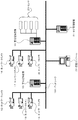
図14はこのような従来の監視システムの一例を示す構成ブロック図である。図14において、1,2,3,5,6及び7はWebサーバ機能を有するネットワークカメラ、4及び8はWebサーバ機能の有し前記ネットワークカメラで撮影された画像を収集し記録する画像記録装置、9は侵入センサ等のセンサ、10はWebサーバ機能を有し発生するイベントやシステム関連のログを管理するログ管理装置、11は中央監視室等に設置されたモニタ装置、100はLAN(Local Area Network)やインターネット等の汎用のネットワークである。 FIG. 14 is a block diagram showing an example of such a conventional monitoring system. In FIG. 14, 1, 2, 3, 5, 6 and 7 are network cameras having a Web server function, and 4 and 8 are image recording apparatuses which have a Web server function and collect and record images taken by the network camera. , 9 is a sensor such as an intrusion sensor, 10 is a log management device that has a Web server function and manages events and system-related logs, 11 is a monitor device installed in a central monitoring room, and 100 is a LAN (Local A general-purpose network such as an area network or the Internet.
ネットワークカメラ1,2,3,5,6及び7は監視対象領域等に分散配置されると共にネットワーク100に接続され、画像記録装置4及び8もまた分散配置されると共にネットワーク100に接続される。 The network cameras 1, 2, 3, 5, 6 and 7 are distributed in the monitoring target area and connected to the network 100, and the image recording apparatuses 4 and 8 are also distributed and connected to the network 100.
センサ9は画像記録装置8に接続され、ログ管理装置10及びモニタ装置11はネットワーク100に接続される。
The sensor 9 is connected to the image recording device 8, and the log management device 10 and the
ここで、図14に示す従来例を図15及び図16を用いて説明する。図15はモニタ装置11の動作を説明するフロー図、図16はモニタ装置11の表示画面の一例を示す説明図である。
Here, the conventional example shown in FIG. 14 will be described with reference to FIGS. FIG. 15 is a flowchart for explaining the operation of the
図15中”S001”においてモニタ装置11は、キーボードやマウス等の入力手段の操作により記録画像表示が選択されたか否かを判断し、もし、記録画像表示が選択されたと判断した場合には、図15中”S002”においてモニタ装置11は、Webブラウザを用いて画像記録装置4若しくは画像記録装置8のWebサーバにアクセスして必要とする画像を表示させる。
In “S001” in FIG. 15, the
もし、図15中”S001”において記録画像表示が選択されなかったと判断した場合には、図15中”S003”においてモニタ装置11は、キーボードやマウス等の入力手段の操作によりカメラ操作が選択されたか否かを判断し、もし、カメラ操作が選択されたと判断した場合には、図15中”S004”においてモニタ装置11は、Webブラウザを用いてネットワークカメラのWebサーバにアクセスして必要とする操作を行う。
If it is determined that the recorded image display is not selected in “S001” in FIG. 15, the
もし、図15中”S003”においてカメラ操作が選択されなかったと判断した場合には、図15中”S005”においてモニタ装置11は、キーボードやマウス等の入力手段の操作によりログ管理が選択されたか否かを判断し、もし、ログ管理が選択されたと判断した場合には、図15中”S006”においてモニタ装置11は、Webブラウザを用いてログ管理装置10のWebサーバにアクセスして必要とするログ情報を取得して表示させる。
If it is determined that the camera operation is not selected in “S003” in FIG. 15, whether or not the log management is selected by the
例えば、図16中”DS01”に示すモニタ装置11の表示画面上には図16中”WD01”に示す画像記録装置のWebサーバの画面、図16中”WD02”に示すネットワークカメラのWebサーバの画面及び図16中”WD03”に示すログ管理装置のWebサーバの画面が表示され、各画面上で必要な操作を行うことにより、記録画像の表示やカメラ操作等を行うことが可能になる。
For example, on the display screen of the
この結果、ネットワーク上に分散配置される各装置にWebサーバ機能を持たせ、中央監視室当に設置されたモニタ装置11からWebブラウザを用いてそれぞれのWebサーバにアクセスして必要な操作を行うことにより、分散配置された複数の装置を集中的に管理することが可能になる。
As a result, each device distributed on the network is provided with a Web server function, and the
しかし、図14に示すような従来例では、モニタ装置11で必要な情報を取得するためには、Webブラウザを用いて該当する装置のWebサーバに個々にアクセスしなければならず、各装置のURL(Uniform Resource Locator)を全て設定する等の煩雑な作業が必要なると共に各装置のWebサーバの画面を個々に確認しなければならないと言った問題点があった。
However, in the conventional example as shown in FIG. 14, in order to acquire necessary information by the
また、Webブラウザで表示した各々の情報は互いに関連していないので、例えば、センサ9でイベント等が発生した場合であっても、センサ9が接続されている画像記録装置8以外の情報を参照している場合には当該発生したイベントを認識することができないと言った問題点があった。
従って本発明が解決しようとする課題は、分散配置された各装置の情報を一画面で把握可能で発生イベントを容易に認識することが可能な監視システムを実現することにある。
In addition, since each information displayed on the Web browser is not related to each other, for example, even when an event or the like occurs in the sensor 9, information other than the image recording device 8 to which the sensor 9 is connected is referred to. However, there was a problem that the event that occurred could not be recognized.
Therefore, the problem to be solved by the present invention is to realize a monitoring system capable of grasping information of each device arranged in a distributed manner on one screen and easily recognizing an occurrence event.
このような課題を達成するために、本発明のうち請求項1記載の発明は、
ネットワーク上に複数のネットワークカメラ、画像記録装置及びログ管理装置を分散配置して画像監視を行う監視システムにおいて、
画像を撮影する複数のネットワークカメラと、複数のセンサが接続されると共に前記ネットワークカメラで撮影された画像を収集し記録する画像記録装置と、ログを管理するログ管理装置と、表示画面を画像コンテンツ切替領域、コンテンツ表示用メニュー領域及びコンテンツ表示領域の3つの領域に分割すると共に、前記画像コンテンツ切替領域に表示可能なコンテンツの一覧を、前記コンテンツ表示用メニュー領域にコンテンツの表示方法の一覧をそれぞれ表示させ、選択されたコンテンツ及び表示方法で前記コンテンツ表示領域にコンテンツを表示させる統括コンソールとを備えたことにより、分散配置された各装置の情報を一画面で把握することが可能になる。
In order to achieve such a problem, the invention according to claim 1 of the present invention is:
In a monitoring system that performs image monitoring by distributing a plurality of network cameras, image recording devices, and log management devices on a network,
A plurality of network cameras that capture images, an image recording device that is connected to a plurality of sensors and that collects and records images captured by the network cameras, a log management device that manages logs, and a display screen that displays image content The display area is divided into three areas, a switching area, a content display menu area, and a content display area, a list of contents that can be displayed in the image content switching area, and a list of content display methods in the content display menu area, respectively. By providing an overall console that displays and displays content in the content display area in accordance with the selected content and display method, it is possible to grasp information on each of the distributed devices on a single screen.
請求項2記載の発明は、
請求項1記載の発明である監視システムにおいて、
前記コンテンツが、
監視システムの管理下にある複数の前記ネットワークカメラの撮影画像、前記画像記録装置に記録された画像、記録画像再生画面、カメラ操作画面、ログ一覧画面、若しくは、
稼動状況監視画面のいずれか1つ以上を含むものであることにより、分散配置された各装置の情報を一画面で把握することが可能になる。
The invention according to claim 2
In the monitoring system according to claim 1,
The content is
Captured images of a plurality of network cameras under management of a monitoring system, images recorded in the image recording device, recorded image playback screen, camera operation screen, log list screen, or
By including any one or more of the operation status monitoring screens, it is possible to grasp information on each of the distributed devices on one screen.
請求項3記載の発明は、
請求項1記載の発明である監視システムにおいて、
前記コンテンツの表示方法が、
ライブ画像表示、巡回画像表示、カメラ操作画面表示、再生画像表示、ログ情報表示、若しくは、関連情報表示のいずれか1つ以上を含むものであることにより、分散配置された各装置の情報を一画面で把握することが可能になる。
The invention described in claim 3
In the monitoring system according to claim 1,
The content display method is:
By including any one or more of live image display, patrol image display, camera operation screen display, playback image display, log information display, and related information display, information on each distributed device can be displayed on a single screen. It becomes possible to grasp.
請求項4記載の発明は、
請求項1記載の発明である監視システムにおいて、
前記統括コンソールが、
予め設定された周期に到達したと判断した場合に、複数の前記ネットワークカメラの何れかに画像取得要求を送信し画像を受信するまで待機するステップを有し、監視システムの管理下にある複数の前記ネットワークカメラの全てから画像を取得するまで前記ステップを繰り返すことにより、分散配置された各装置の情報を一画面で把握することが可能になる。
The invention according to claim 4
In the monitoring system according to claim 1,
The central console is
A step of transmitting an image acquisition request to any one of the plurality of network cameras and waiting until an image is received when it is determined that a preset period has been reached, By repeating the above steps until images are acquired from all of the network cameras, it is possible to grasp information on each of the distributed devices on one screen.
請求項5記載の発明は、
請求項1若しくは請求項2記載の発明である監視システムにおいて、
前記統括コンソールが、
前記画像コンテンツ切替領域に表示可能な前記コンテンツをグループ分けして表示することにより、分散配置された各装置の情報を一画面で把握することが可能になる。
The invention according to claim 5
In the monitoring system which is the invention according to claim 1 or claim 2,
The central console is
By displaying the contents that can be displayed in the image content switching area in groups, it is possible to grasp information on each of the distributed devices on one screen.
請求項6記載の発明は、
請求項5記載の発明である監視システムにおいて、
前記統括コンソールが、
前記グループに属する前記ネットワークカメラをツリー状に表示することにより、分散配置された各装置の情報を一画面で把握することが可能になる。
The invention described in claim 6
In the monitoring system according to claim 5,
The central console is
By displaying the network cameras belonging to the group in a tree shape, it is possible to grasp information on each of the distributed devices on one screen.
請求項7記載の発明は、
請求項5若しくは請求項6記載の発明である監視システムにおいて、
前記統括コンソールが、
グループ登録があった場合に指定された前記ネットワークカメラをひとつのグループとして登録し、前記画像コンテンツ切替領域の表示を表示し直すことにより、分散配置された各装置の情報を一画面で把握することが可能になる。
The invention described in claim 7
In the monitoring system according to claim 5 or claim 6,
The central console is
By registering the specified network cameras as a group when there is a group registration and redisplaying the display of the image content switching area, it is possible to grasp the information of each distributed device on one screen Is possible.
請求項8記載の発明は、
請求項1若しくは請求項2記載の発明である監視システムにおいて、
前記統括コンソールが、
複数の前記コンテンツを前記コンテンツ表示領域内に分割表示させることにより、分散配置された各装置の情報を一画面で把握することが可能になる。
The invention described in claim 8
In the monitoring system which is the invention according to claim 1 or claim 2,
The central console is
By dividing and displaying a plurality of the contents in the content display area, it becomes possible to grasp information on each of the distributed devices on one screen.
請求項9記載の発明は、
請求項1若しくは請求項2記載の発明である監視システムにおいて、
前記統括コンソールが、
イベント情報を前記画像記録装置から前記ログ管理装置を介して受信した場合に関連するネットワークカメラの画像の表示画面を強調表示することにより、発生イベントを容易に認識することが可能になる。
The invention according to claim 9
In the monitoring system which is the invention according to claim 1 or claim 2,
The central console is
When event information is received from the image recording device via the log management device, the network camera image display screen associated with the event information is highlighted, so that the generated event can be easily recognized.
請求項10記載の発明は、
請求項9記載の発明である監視システムにおいて、
前記画像記録装置が、
接続されている前記センサが動作した場合には動作した前記センサに関連する前記ネットワークカメラの画像を記録し、前記ネットワークを介して前記センサの動作通知を前記ログ管理装置に通知し、前記イベント情報を併せて前記ログ管理装置に送信することにより、発生イベントを容易に認識することが可能になる。
The invention according to claim 10 is:
In the monitoring system of the invention according to claim 9,
The image recording apparatus is
When the connected sensor operates, it records an image of the network camera related to the operated sensor, notifies the log management device of the operation notification of the sensor via the network, and the event information. Is transmitted to the log management device, the generated event can be easily recognized.
請求項11記載の発明は、
請求項10記載の発明である監視システムにおいて、
前記ログ管理装置が、
前記ネットワークを介して前記動作通知を受信した場合に前記動作通知と共に受信した前記イベント情報をログとして保存して管理し、前記ネットワークを介して前記統括コンソールに受信した前記イベント情報を転送することにより、発生イベントを容易に認識することが可能になる。
The invention according to
In the monitoring system according to claim 10,
The log management device is
When the operation notification is received via the network, the event information received together with the operation notification is stored and managed as a log, and the received event information is transferred to the central console via the network It is possible to easily recognize the event that has occurred.
請求項12記載の発明は、
請求項11記載の発明である監視システムにおいて、
前記統括コンソールが、
前記ネットワークを介して前記ログ管理装置から前記イベント情報を受信した場合に前記イベント情報に基づきイベントに関連するネットワークカメラを特定し、特定したネットワークカメラに該当する表示画面を強調表示させることにより、発生イベントを容易に認識することが可能になる。
The invention according to claim 12
The monitoring system according to
The central console is
When the event information is received from the log management device via the network, the network camera related to the event is identified based on the event information, and the display screen corresponding to the identified network camera is highlighted, Events can be easily recognized.
請求項13記載の発明は、
請求項9乃至請求項12のいずれかに記載の発明である監視システムにおいて、
前記イベント情報が、
イベントの発生日時、動作したセンサ名、関連するネットワークカメラ名を含むことにより、発生イベントを容易に認識することが可能になる。
The invention according to claim 13
In the monitoring system which is the invention according to any one of claims 9 to 12,
The event information is
By including the date and time of event occurrence, the name of the sensor that operated, and the name of the associated network camera, it is possible to easily recognize the occurrence event.
請求項14記載の発明は、
請求項9若しくは請求項12記載の発明である監視システムにおいて、
前記統括コンソールが、
前記関連するネットワークカメラの画像の表示画面の周囲を枠で囲むことにより、表示画面の周囲を点滅表示させることにより、表示画面そのものを点滅表示させることにより、若しくは、表示画面の表示色を変更することにより強調表示させることにより、発生イベントを容易に認識することが可能になる。
The invention according to claim 14
In the monitoring system which is the invention according to claim 9 or claim 12,
The central console is
Surrounding the display screen of the related network camera image with a frame, flashing the periphery of the display screen, flashing the display screen itself, or changing the display color of the display screen Thus, it is possible to easily recognize the generated event by highlighting.
本発明によれば次のような効果がある。
請求項1,2,3,4,5,6,7及び請求項8の発明によれば、統括コンソールが表示画面を画像コンテンツ切替領域、コンテンツ表示用メニュー領域及びコンテンツ表示領域の3つの領域に分割すると共に、画像コンテンツ切替領域に表示可能なコンテンツの一覧を、コンテンツ表示用メニュー領域にコンテンツの表示方法の一覧をそれぞれ表示させ、選択されたコンテンツ及び表示方法でコンテンツ表示領域にコンテンツを表示させることにより、分散配置された各装置の情報を一画面で把握することが可能になる。
The present invention has the following effects.
According to the first, second, third, fourth, fifth, sixth and seventh and eighth aspects of the invention, the overall console displays the display screen in three areas: an image content switching area, a content display menu area and a content display area. In addition to dividing, a list of contents that can be displayed in the image content switching area, a list of content display methods in the content display menu area, and a content in the content display area in accordance with the selected content and display method are displayed. As a result, it is possible to grasp information on each of the distributed devices on one screen.
また、請求項9,10,11,12,13及び請求項14の発明によれば、統括コンソールがイベントの発生日時、動作したセンサ名、関連するネットワークカメラ名等のイベント情報を前記画像記録装置から前記ログ管理装置を介して受信した場合に関連するネットワークカメラの画像の表示画面を強調表示することにより、発生イベントを容易に認識することが可能になる。 According to the ninth, tenth, eleventh, twelfth, thirteenth and fourteenth aspects of the present invention, the event information such as the event occurrence date and time, the name of the operated sensor, and the name of the associated network camera is recorded by the central console. It is possible to easily recognize the generated event by highlighting the display screen of the image of the network camera related to the case of receiving from the log management device.
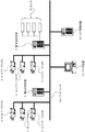
以下本発明を図面を用いて詳細に説明する。図1は本発明に係る監視システムの一実施例を示す構成ブロック図である。図1において、12,13,14,16,17,18はネットワークカメラ、15及び19は前記ネットワークカメラで撮影された画像を収集し記録する画像記録装置、20は侵入センサ等のセンサ、21は発生するイベントやシステム関連のログを管理するログ管理装置、22は中央監視室等に設置された統括コンソール、101はLANやインターネット等の汎用のネットワークである。 Hereinafter, the present invention will be described in detail with reference to the drawings. FIG. 1 is a block diagram showing the configuration of an embodiment of a monitoring system according to the present invention. In FIG. 1, 12, 13, 14, 16, 17, and 18 are network cameras, 15 and 19 are image recording devices that collect and record images taken by the network camera, 20 is a sensor such as an intrusion sensor, and 21 is A log management device for managing events and system-related logs that occur, 22 is a general console installed in a central monitoring room, and 101 is a general-purpose network such as a LAN or the Internet.
ネットワークカメラ12,13,14,16,17及び18は監視対象領域等に分散配置されると共にネットワーク101に接続され、画像記録装置15及び19もまた分散配置されると共にネットワーク101に接続される。
The network cameras 12, 13, 14, 16, 17 and 18 are distributed in the monitoring target area and connected to the
センサ20は画像記録装置19に接続され、ログ管理装置21及び統括コンソール22はネットワーク101に接続される。
The sensor 20 is connected to the image recording device 19, and the log management device 21 and the overall console 22 are connected to the
ここで、図1に示す実施例の動作を図2、図3及び図4を用いて説明する。図2は統括コンソール22の画像取得の動作を説明するフロー図、図3は統括コンソール22の画像表示の動作を説明するフロー図、図4は統括コンソール22の表示画面の一例を示す説明図である。 Here, the operation of the embodiment shown in FIG. 1 will be described with reference to FIGS. FIG. 2 is a flowchart for explaining the image acquisition operation of the overall console 22, FIG. 3 is a flowchart for explaining the image display operation of the overall console 22, and FIG. 4 is an explanatory view showing an example of the display screen of the overall console 22. is there.
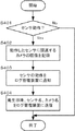
まず第1に、図2中”S101”において統括コンソール22は、予め設定された周期に到達したか否かを判断し、設定周期に到達したと判断した場合には、図2中”S102”において統括コンソール22は、ネットワークカメラ12,13,14,16,17,18の何れかに画像取得要求を送信し図2中”S103”において画像を受信するまで待機する。 First, in “S101” in FIG. 2, the overall console 22 determines whether or not a preset period has been reached. If it is determined that the set period has been reached, “S102” in FIG. The central console 22 transmits an image acquisition request to any of the network cameras 12, 13, 14, 16, 17, and 18 and waits until an image is received in "S103" in FIG.
そして、図2中”S104”において統括コンソール22は管理下にある全てのネットワークカメラから画像を取得したか否かを判断し、もし、管理下にある全てのネットワークカメラから画像を取得し終えていない場合には、図2中”S102”のステップに戻り、管理下にある全てのネットワークカメラから画像の取得を完了している場合には、図2中”S101”のステップに戻る。 Then, in “S104” in FIG. 2, the overall console 22 determines whether images have been acquired from all the network cameras under management, and has finished acquiring images from all the network cameras under management. If not, the process returns to the “S102” step in FIG. 2, and if image acquisition has been completed from all the network cameras under management, the process returns to the “S101” step in FIG.
このように複数のネットワークカメラから画像を取得した後、図3中”S201”において統括コンソール22は、表示画面を3つの領域に分割する。 After acquiring images from a plurality of network cameras in this way, the overall console 22 divides the display screen into three areas in “S201” in FIG.
例えば、図4中”WD11”に示すように統括コンソール22は表示画面を、図4中”CC11”に示す画像コンテンツ切替領域、図4中”CM11”に示すコンテンツ表示用メニュー領域及び図4中”CD11”に示すコンテンツ表示領域の3つの領域に分割する。 For example, as shown by “WD11” in FIG. 4, the overall console 22 displays a display screen, an image content switching area indicated by “CC11” in FIG. 4, a menu area for content display indicated by “CM11” in FIG. The area is divided into three areas of the content display area indicated by “CD11”.
図3中”S202”において統括コンソール22は、画像コンテンツ切替領域に表示可能なコンテンツの一覧を表示させる。 In “S202” in FIG. 3, the overall console 22 displays a list of contents that can be displayed in the image content switching area.
例えば、統括コンソール22は、図4中”CC11”に示す画像コンテンツ切替領域に、監視システムの管理下にあるネットワークカメラの撮影画像、画像記録装置に記録された画像、記録画像再生画面、カメラ操作画面、ログ一覧画面、稼動状況監視画面及びその他の画面等と言ったコンテンツの一覧を表示させる。 For example, the overall console 22 displays, in the image content switching area indicated by “CC11” in FIG. 4, a captured image of the network camera under the management of the monitoring system, an image recorded in the image recording device, a recorded image playback screen, and a camera operation. A list of contents such as a screen, a log list screen, an operation status monitoring screen, and other screens is displayed.
同様に、図3中”S203”において統括コンソール22は、コンテンツ表示用メニュー領域に表示可能なコンテンツの表示方法の一覧を表示させる。 Similarly, in "S203" in FIG. 3, the overall console 22 displays a list of content display methods that can be displayed in the content display menu area.
例えば、統括コンソール22は、図4中”CM11”に示すコンテンツ表示用メニュー領域に、ライブ画像表示、巡回画像表示、カメラ操作画面表示、再生画像表示、ログ情報表示及び関連情報表示等と言った選択したコンテンツの表示方法の一覧を表示させる。 For example, in the content display menu area indicated by “CM11” in FIG. 4, the overall console 22 says live image display, patrol image display, camera operation screen display, playback image display, log information display, related information display, and the like. Display a list of display methods for the selected content.
そして、図3中”S204”において統括コンソール22は、図4中”CC11”に示す画像コンテンツ切替領域、或いは、図4中”CM11”に示すコンテンツ表示用メニュー領域でコンテンツ或いは表示方法が選択されたか否かを判断する。 Then, in “S204” in FIG. 3, the overall console 22 selects a content or display method in the image content switching area indicated by “CC11” in FIG. 4 or the content display menu area indicated by “CM11” in FIG. It is determined whether or not.
例えば、統括コンソール22は、キーボードやマウス等の入力手段の操作によって上述のコンテンツの一覧から表示させたいコンテンツを選択されたか、或いは、コンテンツの表示方法が選択されたかを判断する。 For example, the overall console 22 determines whether the content to be displayed has been selected from the above-described content list or the content display method has been selected by operating an input unit such as a keyboard or a mouse.
もし、図3中”S204”においてコンテンツ等が選択されたと判断された場合には、図3中”S205”において統括コンソール22は、選択されたコンテンツ或いは選択された表示方法で図4中”CD11”に示すコンテンツ表示領域にコンテンツを表示させる。 If it is determined that content or the like is selected in “S204” in FIG. 3, the central console 22 in “S205” in FIG. 3 uses “CD11” in FIG. 4 with the selected content or the selected display method. The content is displayed in the content display area indicated by “”.
一方、もし、図3中”S204”においてコンテンツ等が選択されていない判断された場合には、図3中”S206”において統括コンソール22は、予め設定されている既定のコンテンツ及び表示方法で図4中”CD11”に示すコンテンツ表示領域にコンテンツを表示させる。 On the other hand, if it is determined in “S204” in FIG. 3 that content or the like has not been selected, the overall console 22 displays in the “S206” in FIG. 3 using the preset default content and display method. 4, the content is displayed in the content display area indicated by “CD11”.
この結果、統括コンソール22が、表示画面を画像コンテンツ切替領域、コンテンツ表示用メニュー領域及びコンテンツ表示領域の3つの領域に分割すると共に、画像コンテンツ切替領域に表示可能なコンテンツの一覧を、コンテンツ表示用メニュー領域にコンテンツの表示方法の一覧をそれぞれ表示させ、選択されたコンテンツ及び表示方法でコンテンツ表示領域にコンテンツを表示させることにより、分散配置された各装置の情報を一画面で把握することが可能になる。 As a result, the overall console 22 divides the display screen into three areas: an image content switching area, a content display menu area, and a content display area, and a list of contents that can be displayed in the image content switching area is displayed for content display. By displaying a list of content display methods in the menu area and displaying the content in the content display area with the selected content and display method, it is possible to grasp information on each distributed device on a single screen. become.
なお、図1に示す実施例の説明に際しては、図4中”CC11”に示すコンテンツ切替領域には表示可能なコンテンツの一覧を表示させているが、コンテンツをグループ分けして表示しても勿論構わない。 In the description of the embodiment shown in FIG. 1, a list of contents that can be displayed is displayed in the content switching area indicated by “CC11” in FIG. 4, but the contents may be displayed in groups. I do not care.
図5はこのようなコンテンツのグループ分けをした場合の統括コンソール22の表示画面の一例を示す説明図であり、コンテンツ切替領域には図5中”TR21”に示すようなツリー状のコンテンツ一覧が表示される。 FIG. 5 is an explanatory diagram showing an example of the display screen of the overall console 22 when such content grouping is performed, and a tree-like content list such as “TR21” in FIG. 5 is displayed in the content switching area. Is displayed.
ここで、図5に示すようなコンテンツのグループ分けを図6及び図7を用いて説明する。図6は統括コンソール22のグループ分けの動作を説明するフロー図、図7はツリー状のコンテンツ一覧の詳細を示す説明図である。 Here, content grouping as shown in FIG. 5 will be described with reference to FIGS. FIG. 6 is a flowchart for explaining the grouping operation of the overall console 22, and FIG. 7 is an explanatory diagram showing details of a tree-like content list.
図1中のネットワークカメラ12,13及び14を”グループ1”に、ネットワークカメラ16,17及び18を”グループ2”にそれぞれグループ分けする場合を想定する。 Assume that the network cameras 12, 13 and 14 in FIG. 1 are grouped into "Group 1", and the network cameras 16, 17 and 18 are grouped into "Group 2".
図6中”S301”において統括コンソール22は、グループ登録がなされたか否かを判断し、グループ登録があった場合には、図6中”S302”において統括コンソール22は、指定されたネットワークカメラをひとつのグループとして登録すると共に図6中”S303”において画像コンテンツ切替領域の表示を表示し直す。 In “S301” in FIG. 6, the central console 22 determines whether or not group registration has been performed. If there is group registration, the central console 22 selects the designated network camera in “S302” in FIG. In addition to registering as one group, the display of the image content switching area is displayed again in “S303” in FIG.
例えば、統括コンソール22は、画像コンテンツ切替領域内に図7中”GR31”及び”GR32”に示すような”グループ1”及び”グループ2”を表示させると共に当該グループに属するネットワークカメラをツリー状に表示させる。 For example, the overall console 22 displays “Group 1” and “Group 2” as indicated by “GR31” and “GR32” in FIG. 7 in the image content switching area, and network cameras belonging to the group in a tree shape. Display.
すなわち、図7中”GR31”に示す”グループ1”の下には当該グループに属するネットワークカメラ12,13及び14を図7中”CM31”、”CM32”及び”CM33”に示すように表示させる。 That is, under “Group 1” shown in “GR31” in FIG. 7, the network cameras 12, 13, and 14 belonging to the group are displayed as shown in “CM31”, “CM32”, and “CM33” in FIG. .
同様に、図7中”GR32”に示す”グループ2”の下には当該グループに属するネットワークカメラ16,17及び18を図7中”CM34”、”CM35”及び”CM36”に示すように表示させる。 Similarly, under “Group 2” shown in “GR32” in FIG. 7, the network cameras 16, 17 and 18 belonging to the group are displayed as shown in “CM34”, “CM35” and “CM36” in FIG. Let
また、図1に示す実施例ではコンテンツ表示領域に選択されたコンテンツを表示させる旨説明しているが、複数のコンテンツを当該コンテンツ表示領域内に分割表示させても勿論構わない。 Further, in the embodiment shown in FIG. 1, it has been described that the selected content is displayed in the content display area, but it goes without saying that a plurality of contents may be divided and displayed in the content display area.
例えば、図8はこのような9つのネットワークカメラで撮影した画像の分割表示の一例を示す説明図である。 For example, FIG. 8 is an explanatory diagram showing an example of split display of images taken by such nine network cameras.
すなわち、統括コンソール22は、図8中”CD11”に示すコンテンツ表示領域内に図8中”DS41”、”DS42”、”DS43”、”DS44”、”DS45”、”DS46”、”DS47”、”DS48”及び”DS49”に示すような9つのネットワークカメラで撮影した画像分割表示させる。 That is, the overall console 22 displays “DS41”, “DS42”, “DS43”, “DS44”, “DS45”, “DS46”, “DS47” in FIG. 8 within the content display area indicated by “CD11” in FIG. , “DS48” and “DS49” as shown in FIG.
また、図8に示すように単純に分割表示させるのではなく、分割表示をさせると共に予め設定されたグループ(例えば、図7で定義したようなネットワークカメラのグループ)間で表示(分割表示)を定周期で順次切り替える(巡回表示)ことにより、多数のネットワークカメラの画像表示を一定時間内に行うことが可能になる。 Further, instead of simply dividing and displaying as shown in FIG. 8, the display is divided and displayed (divided display) between preset groups (for example, network camera groups as defined in FIG. 7). By sequentially switching (cyclic display) at regular intervals, it becomes possible to display images from a number of network cameras within a certain time.
また、コンテンツ表示用メニュー領域で”カメラ操作画面表示”を選択することにより、統括コンソール22の表示手段には図9に示すような表示画面が表示される。図9はカメラ操作画面表示による表示方法を選択した場合の表示画面の一例を示す説明図である。 Further, by selecting “camera operation screen display” in the content display menu area, a display screen as shown in FIG. 9 is displayed on the display means of the overall console 22. FIG. 9 is an explanatory diagram illustrating an example of a display screen when a display method based on camera operation screen display is selected.
すなわち、統括コンソール22は、図9中”CD11”に示すコンテンツ表示領域内に図9中”DS51”に示すような或るネットワークカメラで撮影した画像を表示させると共に図9中”BT51”若しくは”BT52”に示すような各種操作ボタンやスイッチ等を表示させ、当該操作ボタン等を操作させることにより、ネットワークカメラのズーム、パン、チルト、画角等のパラメータを修正・変更等することが可能になる。 That is, the overall console 22 displays an image photographed by a certain network camera as indicated by “DS51” in FIG. 9 in the content display area indicated by “CD11” in FIG. 9 and “BT51” or “ By displaying various operation buttons and switches as shown in BT52 "and operating the operation buttons, it is possible to modify / change parameters such as zoom, pan, tilt, and angle of view of the network camera. Become.
また、ここで、イベント発生に伴う監視システムの動作を図10、図11、図12及び図13を用いて詳細に説明する。図10はイベントを検出するセンサ20は接続された画像記録装置19の動作を説明するフロー図、図11はログ管理装置21の動作を説明するフロー図、図12は統括コンソール22の動作を説明するフロー図、図13は統括コンソール22の表示画面の一例を示す説明図である。 Here, the operation of the monitoring system accompanying the occurrence of an event will be described in detail with reference to FIG. 10, FIG. 11, FIG. 12, and FIG. 10 is a flowchart for explaining the operation of the image recording device 19 connected to the sensor 20 for detecting an event, FIG. 11 is a flowchart for explaining the operation of the log management device 21, and FIG. 12 explains the operation of the central console 22. FIG. 13 is an explanatory diagram showing an example of a display screen of the overall console 22.
図10中”S401”において画像記録装置19は、接続されているセンサ20が動作したか否かを判断し、言い換えれば、イベントが発生したか否かを判断し、もし、センサ20が動作している(イベント発生)と判断した場合には、図10中”S402”において動作したセンサに関連するネットワークカメラの画像を記録する。 In “S401” in FIG. 10, the image recording apparatus 19 determines whether or not the connected sensor 20 has operated, in other words, determines whether or not an event has occurred, and if the sensor 20 operates. If it is determined that the event has occurred (event occurrence), an image of the network camera related to the sensor operated in “S402” in FIG. 10 is recorded.
そして、図10中”S403”において画像記録装置19は、ネットワーク101を介してセンサの動作通知をログ管理装置21に通知すると共に図10中”S404”において当該イベントの発生日時、動作したセンサ名、関連するネットワークカメラ名等のイベント情報を併せてログ管理装置21に送信する。
Then, in “S403” in FIG. 10, the image recording device 19 notifies the log management device 21 of sensor operation notification via the
一方、図11中”S501”においてログ管理装置21は、ネットワーク101を介して画像記録装置19からセンサの動作通知を受信したか否かを判断し、もし、センサの動作通知を受信した場合には、図11中”S502”においてログ管理装置21は、センサの動作通知と共に受信したイベント情報をログとして保存して管理する。
On the other hand, in “S501” in FIG. 11, the log management device 21 determines whether or not a sensor operation notification is received from the image recording device 19 via the
また、図11中”S503”においてログ管理装置21は、ネットワーク101を介して統括コンソール22に受信したイベント情報を転送する。
Further, in “S503” in FIG. 11, the log management apparatus 21 transfers the received event information to the overall console 22 via the
そして、図12中”S601”において統括コンソール22は、ネットワーク101を介してログ管理装置21からイベント情報を受信したか否かを判断し、もし、イベント情報を受信した場合には、図12中”S602”において統括コンソール22は、ログ管理装置21から転送されてきたイベント情報に基づき当該イベントに関連するネットワークカメラを特定すると共に図12中”S603”において特定したネットワークカメラに該当する表示画面を赤枠等で囲んで強調表示させる。
Then, in “S601” in FIG. 12, the overall console 22 determines whether or not event information has been received from the log management apparatus 21 via the
例えば、センサが図13中”EV61”に示すようなイベントの発生を検出し、当該イベントに関連するネットワークカメラの画像が図13中”CD11”に示すコンテンツ表示領域内の図13中”DS61”に示す表示画面に表示されていると統括コンソール22が判断すれば、図13中”EM61”に示すように当該表示画面の周囲を赤枠で囲んで強調表示させる。 For example, the sensor detects the occurrence of an event as indicated by “EV61” in FIG. 13, and the image of the network camera related to the event is “DS61” in FIG. 13 in the content display area indicated by “CD11” in FIG. If the overall console 22 determines that the image is displayed on the display screen shown in FIG. 13, the periphery of the display screen is highlighted with a red frame as shown by “EM61” in FIG.
すなわち、センサが動作(イベントが発生)した場合に、センサが接続された画像記録装置19がイベントの発生日時、動作したセンサ名、関連するネットワークカメラ名等のイベント情報をログ管理装置21を介して統括コンソール22に転送し、統括コンソール22が関連するネットワークカメラの画像の表示画面を強調表示することにより、従来のセンサ20が接続されている画像記録装置19以外の情報を参照している場合には当該発生したイベントを認識することができないと言った問題が改善される。 That is, when a sensor operates (an event occurs), the image recording device 19 to which the sensor is connected sends event information such as the event occurrence date and time, the name of the operated sensor, and the associated network camera name via the log management device 21. When the information is transferred to the general console 22 and the general console 22 highlights the image display screen of the related network camera, the information other than the image recording device 19 to which the conventional sensor 20 is connected is referred to. The problem of not being able to recognize the event that occurred is improved.
この結果、統括コンソール22が、イベントの発生日時、動作したセンサ名、関連するネットワークカメラ名等のイベント情報を前記画像記録装置から前記ログ管理装置を介して受信した場合に、関連するネットワークカメラの画像の表示画面を強調表示することにより、発生イベントを容易に認識することが可能になる。 As a result, when the general console 22 receives event information such as the event occurrence date and time, the name of the sensor that has been operated, and the name of the associated network camera from the image recording device via the log management device, By highlighting the image display screen, the generated event can be easily recognized.
また、図13等に示す事例では発生イベントに関連するネットワークカメラの画像の表示画面の周囲を赤枠等で囲んで強調表示させているが、表示画面の周囲を点滅表示させたり、表示画面そのものを点滅表示させたり、表示画面の表示色を変更したりして強調表示させても勿論構わない。 In the example shown in FIG. 13 and the like, the periphery of the network camera image display screen related to the occurrence event is highlighted with a red frame or the like, but the periphery of the display screen is flashed or the display screen itself is displayed. Of course, it is also possible to highlight the display by blinking or changing the display color of the display screen.
1,2,3,5,6,7、12,13,14,16,17,18 ネットワークカメラ
4,8,15,19 画像記録装置
9,20 センサ
10,21 ログ管理装置
11 モニタ装置
22 統括コンソール
100、101 ネットワーク
1, 2, 3, 5, 6, 7, 12, 13, 14, 16, 17, 18 Network camera 4, 8, 15, 19 Image recording device 9, 20 Sensor 10, 21
Claims (14)
画像を撮影する複数のネットワークカメラと、
複数のセンサが接続されると共に前記ネットワークカメラで撮影された画像を収集し記録する画像記録装置と、
ログを管理するログ管理装置と、
表示画面を画像コンテンツ切替領域、コンテンツ表示用メニュー領域及びコンテンツ表示領域の3つの領域に分割すると共に、前記画像コンテンツ切替領域に表示可能なコンテンツの一覧を、前記コンテンツ表示用メニュー領域にコンテンツの表示方法の一覧をそれぞれ表示させ、選択されたコンテンツ及び表示方法で前記コンテンツ表示領域にコンテンツを表示させる統括コンソールとを備えたことを特徴とする監視システム。 In a monitoring system that performs image monitoring by distributing a plurality of network cameras, image recording devices, and log management devices on a network,
Multiple network cameras that take images,
An image recording apparatus for collecting and recording an image captured by the network camera while being connected to a plurality of sensors;
A log management device for managing logs;
The display screen is divided into three areas: an image content switching area, a content display menu area, and a content display area, and a list of contents that can be displayed in the image content switching area is displayed in the content display menu area. A monitoring system, comprising: a central console for displaying a list of methods and displaying content in the content display area according to a selected content and display method.
監視システムの管理下にある複数の前記ネットワークカメラの撮影画像、前記画像記録装置に記録された画像、記録画像再生画面、カメラ操作画面、ログ一覧画面、若しくは、
稼動状況監視画面のいずれか1つ以上を含むものであることを特徴とする
請求項1記載の監視システム。 The content is
Captured images of a plurality of network cameras under management of a monitoring system, images recorded in the image recording device, recorded image playback screen, camera operation screen, log list screen, or
The monitoring system according to claim 1, comprising any one or more of operating status monitoring screens.
ライブ画像表示、巡回画像表示、カメラ操作画面表示、再生画像表示、ログ情報表示、若しくは、関連情報表示のいずれか1つ以上を含むものであることを特徴とする
請求項1記載の監視システム。 The content display method is:
The monitoring system according to claim 1, comprising at least one of live image display, patrol image display, camera operation screen display, playback image display, log information display, and related information display.
予め設定された周期に到達したと判断した場合に、複数の前記ネットワークカメラの何れかに画像取得要求を送信し画像を受信するまで待機するステップを有し、
監視システムの管理下にある複数の前記ネットワークカメラの全てから画像を取得するまで前記ステップを繰り返すことを特徴とする
請求項1記載の監視システム。 The central console is
When it is determined that a preset period has been reached, the method includes a step of waiting until an image acquisition request is transmitted to any of the plurality of network cameras and an image is received;
The monitoring system according to claim 1, wherein the steps are repeated until images are acquired from all of the plurality of network cameras under management of the monitoring system.
前記画像コンテンツ切替領域に表示可能な前記コンテンツをグループ分けして表示することを特徴とする
請求項1若しくは請求項2記載の監視システム。 The central console is
The monitoring system according to claim 1 or 2, wherein the contents that can be displayed in the image content switching area are displayed in groups.
前記グループに属する前記ネットワークカメラをツリー状に表示することを特徴とする
請求項5記載の監視システム。 The central console is
6. The monitoring system according to claim 5, wherein the network cameras belonging to the group are displayed in a tree shape.
グループ登録があった場合に指定された前記ネットワークカメラをひとつのグループとして登録し、
前記画像コンテンツ切替領域の表示を表示し直すことを特徴とする
請求項5若しくは請求項6記載の監視システム。 The central console is
Register the specified network camera as a group when there is a group registration,
7. The monitoring system according to claim 5, wherein the display of the image content switching area is displayed again.
複数の前記コンテンツを前記コンテンツ表示領域内に分割表示させることを特徴とする
請求項1若しくは請求項2記載の監視システム。 The central console is
The monitoring system according to claim 1 or 2, wherein a plurality of the contents are divided and displayed in the content display area.
イベント情報を前記画像記録装置から前記ログ管理装置を介して受信した場合に関連するネットワークカメラの画像の表示画面を強調表示することを特徴とする
請求項1若しくは請求項2記載の監視システム。 The central console is
The monitoring system according to claim 1 or 2, wherein a display screen of an image of a network camera associated with event information received from the image recording device via the log management device is highlighted.
接続されている前記センサが動作した場合には動作した前記センサに関連する前記ネットワークカメラの画像を記録し、
前記ネットワークを介して前記センサの動作通知を前記ログ管理装置に通知し、
前記イベント情報を併せて前記ログ管理装置に送信することを特徴とする
請求項9記載の監視システム。 The image recording apparatus is
When the connected sensor operates, record an image of the network camera related to the operated sensor,
Notifying the log management device of the operation notification of the sensor via the network,
The monitoring system according to claim 9, wherein the event information is also transmitted to the log management apparatus.
前記ネットワークを介して前記動作通知を受信した場合に前記動作通知と共に受信した前記イベント情報をログとして保存して管理し、
前記ネットワークを介して前記統括コンソールに受信した前記イベント情報を転送することを特徴とする
請求項10記載の監視システム。 The log management device is
When the operation notification is received via the network, the event information received together with the operation notification is stored and managed as a log,
The monitoring system according to claim 10, wherein the received event information is transferred to the central console via the network.
前記ネットワークを介して前記ログ管理装置から前記イベント情報を受信した場合に前記イベント情報に基づきイベントに関連するネットワークカメラを特定し、
特定したネットワークカメラに該当する表示画面を強調表示させることを特徴とする
請求項11記載の監視システム。 The central console is
When the event information is received from the log management device via the network, the network camera related to the event is identified based on the event information,
The monitoring system according to claim 11, wherein a display screen corresponding to the identified network camera is highlighted.
イベントの発生日時、動作したセンサ名、関連するネットワークカメラ名を含むことを特徴とする
請求項9乃至請求項12のいずれかに記載の監視システム。 The event information is
The monitoring system according to any one of claims 9 to 12, including an event occurrence date and time, a name of an operated sensor, and a related network camera name.
前記関連するネットワークカメラの画像の表示画面の周囲を枠で囲むことにより、表示画面の周囲を点滅表示させることにより、表示画面そのものを点滅表示させることにより、若しくは、表示画面の表示色を変更することにより強調表示させることを特徴とする
請求項9若しくは請求項12記載の監視システム。
The central console is
Surrounding the display screen of the related network camera image with a frame, flashing the periphery of the display screen, flashing the display screen itself, or changing the display color of the display screen The monitoring system according to claim 9 or 12, wherein the monitoring system is highlighted.
Priority Applications (1)
| Application Number | Priority Date | Filing Date | Title |
|---|---|---|---|
| JP2003360336A JP2005129999A (en) | 2003-10-21 | 2003-10-21 | Monitoring system |
Applications Claiming Priority (1)
| Application Number | Priority Date | Filing Date | Title |
|---|---|---|---|
| JP2003360336A JP2005129999A (en) | 2003-10-21 | 2003-10-21 | Monitoring system |
Publications (1)
| Publication Number | Publication Date |
|---|---|
| JP2005129999A true JP2005129999A (en) | 2005-05-19 |
Family
ID=34640671
Family Applications (1)
| Application Number | Title | Priority Date | Filing Date |
|---|---|---|---|
| JP2003360336A Pending JP2005129999A (en) | 2003-10-21 | 2003-10-21 | Monitoring system |
Country Status (1)
| Country | Link |
|---|---|
| JP (1) | JP2005129999A (en) |
Cited By (9)
| Publication number | Priority date | Publication date | Assignee | Title |
|---|---|---|---|---|
| JP2007180829A (en) * | 2005-12-27 | 2007-07-12 | Canon Marketing Japan Inc | Monitoring system, monitoring method, and program for executing method |
| JP2008252473A (en) * | 2007-03-30 | 2008-10-16 | Rf Logitech Kk | Video recording system |
| JP2010028401A (en) * | 2008-07-18 | 2010-02-04 | Hitachi Ltd | Monitoring camera system |
| KR100966783B1 (en) | 2007-09-19 | 2010-06-29 | 캐논 가부시끼가이샤 | Information processing apparatus, control method of information processing apparatus and storage medium |
| KR20140020039A (en) | 2012-08-07 | 2014-02-18 | 삼성테크윈 주식회사 | Network camera and surveillance system includint the same |
| JP2016144045A (en) * | 2015-02-02 | 2016-08-08 | キヤノン株式会社 | Output device, image monitoring system, information processing method, and program |
| CN106231274A (en) * | 2016-09-23 | 2016-12-14 | 国网上海市电力公司 | Electric power website communication power supply monitoring system based on ARM and monitoring method |
| JP2018117373A (en) * | 2018-03-09 | 2018-07-26 | キヤノンマーケティングジャパン株式会社 | Network camera system, control method, and program |
| KR20190080448A (en) * | 2017-12-28 | 2019-07-08 | 주식회사 앤다스 | Control System And Method Based On GIS |
-
2003
- 2003-10-21 JP JP2003360336A patent/JP2005129999A/en active Pending
Cited By (10)
| Publication number | Priority date | Publication date | Assignee | Title |
|---|---|---|---|---|
| JP2007180829A (en) * | 2005-12-27 | 2007-07-12 | Canon Marketing Japan Inc | Monitoring system, monitoring method, and program for executing method |
| JP2008252473A (en) * | 2007-03-30 | 2008-10-16 | Rf Logitech Kk | Video recording system |
| KR100966783B1 (en) | 2007-09-19 | 2010-06-29 | 캐논 가부시끼가이샤 | Information processing apparatus, control method of information processing apparatus and storage medium |
| JP2010028401A (en) * | 2008-07-18 | 2010-02-04 | Hitachi Ltd | Monitoring camera system |
| KR20140020039A (en) | 2012-08-07 | 2014-02-18 | 삼성테크윈 주식회사 | Network camera and surveillance system includint the same |
| JP2016144045A (en) * | 2015-02-02 | 2016-08-08 | キヤノン株式会社 | Output device, image monitoring system, information processing method, and program |
| CN106231274A (en) * | 2016-09-23 | 2016-12-14 | 国网上海市电力公司 | Electric power website communication power supply monitoring system based on ARM and monitoring method |
| KR20190080448A (en) * | 2017-12-28 | 2019-07-08 | 주식회사 앤다스 | Control System And Method Based On GIS |
| KR102047964B1 (en) * | 2017-12-28 | 2020-01-08 | 주식회사 앤다스 | Control System And Method Based On GIS |
| JP2018117373A (en) * | 2018-03-09 | 2018-07-26 | キヤノンマーケティングジャパン株式会社 | Network camera system, control method, and program |
Similar Documents
| Publication | Publication Date | Title |
|---|---|---|
| US11064160B2 (en) | Systems and methods for video monitoring using linked devices | |
| KR100442170B1 (en) | Remote Control and Management System | |
| US20180367763A1 (en) | Systems and methods for managing and displaying video sources | |
| JP6431257B2 (en) | NETWORK SYSTEM, NETWORK DEVICE MANAGEMENT METHOD, NETWORK DEVICE, ITS CONTROL METHOD AND PROGRAM, AND MANAGEMENT SYSTEM | |
| CN101201965B (en) | Monitoring apparatus and monitoring method | |
| US20050162268A1 (en) | Digital video surveillance | |
| KR101652856B1 (en) | Apparatus for providing user interface screen based on control event in cctv | |
| JP2005129999A (en) | Monitoring system | |
| JPWO2015040732A1 (en) | Video display system and video display method | |
| JP2013109474A (en) | Information processing apparatus, information processing method and program | |
| JP2007068010A (en) | Video monitor system | |
| KR20200085556A (en) | Setting apparatus and control method for setting apparatus | |
| US10791325B2 (en) | Method and system for monitoring equipment state | |
| JP2013101462A (en) | Monitoring device | |
| JP4573244B2 (en) | Information processing apparatus, control method, and program | |
| EP3833013B1 (en) | Video management system and method for dynamic displaying of video streams | |
| JP4192698B2 (en) | Monitoring, operation method and display device | |
| KR20040054266A (en) | A remote surveillance system using digital video recording | |
| JP4733942B2 (en) | Camera system | |
| KR100998038B1 (en) | Multi view processing device of digital video signal and processing method thereof | |
| JP2006304065A (en) | Server for use in remote conference, client computer, control method and program | |
| JP4551813B2 (en) | Computer and program | |
| JP2008118376A (en) | Image monitoring region setting method and system | |
| KR20210100587A (en) | Image managing apparatus with self-diagnosis and method using the same | |
| KR100826685B1 (en) | Apparatus and method for setting record schedule in digital video recorder |
Legal Events
| Date | Code | Title | Description |
|---|---|---|---|
| A621 | Written request for application examination |
Effective date: 20060516 Free format text: JAPANESE INTERMEDIATE CODE: A621 |
|
| A977 | Report on retrieval |
Effective date: 20090310 Free format text: JAPANESE INTERMEDIATE CODE: A971007 |
|
| A131 | Notification of reasons for refusal |
Free format text: JAPANESE INTERMEDIATE CODE: A131 Effective date: 20090319 |
|
| A521 | Written amendment |
Free format text: JAPANESE INTERMEDIATE CODE: A523 Effective date: 20090518 |
|
| A02 | Decision of refusal |
Free format text: JAPANESE INTERMEDIATE CODE: A02 Effective date: 20090610 |