JP2005123797A - Color image processing apparatus, color image processing method, and program - Google Patents
Color image processing apparatus, color image processing method, and program Download PDFInfo
- Publication number
- JP2005123797A JP2005123797A JP2003355213A JP2003355213A JP2005123797A JP 2005123797 A JP2005123797 A JP 2005123797A JP 2003355213 A JP2003355213 A JP 2003355213A JP 2003355213 A JP2003355213 A JP 2003355213A JP 2005123797 A JP2005123797 A JP 2005123797A
- Authority
- JP
- Japan
- Prior art keywords
- color
- color signal
- signal
- black
- amount
- Prior art date
- Legal status (The legal status is an assumption and is not a legal conclusion. Google has not performed a legal analysis and makes no representation as to the accuracy of the status listed.)
- Pending
Links
Images
Landscapes
- Facsimile Image Signal Circuits (AREA)
- Color Image Communication Systems (AREA)
- Color, Gradation (AREA)
- Image Processing (AREA)
Abstract
Description
本発明は、カラー画像信号を処理するカラー画像処理装置等に係り、より詳しくは、入力されたカラー画像信号をカラープリンタ等のカラー画像記録信号に変換するカラー画像処理装置等に関する。 The present invention relates to a color image processing apparatus that processes a color image signal, and more particularly to a color image processing apparatus that converts an input color image signal into a color image recording signal of a color printer or the like.
近年、イエロー(Y)、マゼンタ(M)、シアン(C)およびブラック(K)の4色プロセス印刷で再現できない鮮やかな色を表現するための印刷技術として、レッド(R)、グリーン(G)およびブルー(B)の原色系インクや蛍光インクで構成される特色をYMCK4色に加えて、色再現を行うことが行われている。これら特色の色見本としては、Pantone社の色見本などが知られており、1000色程度の特色が定義されている。ここで、一般に、印刷機では最大で8色までしか同時に印刷することができず、使える特色の数は最大でも8色と非常に少ないことから、デザイナーからは使用できる特色の数を増やして欲しいといった要望が強い。また、版ごとに特色を変更する場合においては、印刷機の清掃作業が発生するため、特色印刷は印刷現場において多大な工数がかかるといった問題があった。更に、印刷のワークフローにおいて、自然画の入稿がデジタルカメラで行われるようになってきており、デジタルカメラの色空間であるsRGB色空間はYMCK4色のプロセスカラー印刷の色域よりも広いことから、忠実再現を目的とした印刷の色域拡大の要求がある。 In recent years, red (R) and green (G) are printing techniques for expressing vivid colors that cannot be reproduced by four-color process printing of yellow (Y), magenta (M), cyan (C), and black (K). In addition, color reproduction is performed by adding special colors composed of primary inks of blue (B) and fluorescent ink to the four colors of YMCK. As color samples of these special colors, Pantone color samples are known, and about 1000 special colors are defined. Here, in general, a printing press can print only up to 8 colors at the same time, and the number of usable spot colors is very small, at most 8 colors, so the designer wants to increase the number of available spot colors. There is a strong demand. Further, when the spot color is changed for each plate, a cleaning operation of the printing press occurs, and therefore, the spot color printing has a problem that it takes a lot of man-hours at the printing site. Furthermore, in the printing workflow, submission of natural images has been performed by digital cameras, and the sRGB color space, which is the color space of digital cameras, is wider than the color gamut of YMCK process color printing. There is a need to expand the color gamut of printing for the purpose of faithful reproduction.
かかる問題や要求に対し、近年の印刷技術において、YMCK4色のプロセスカラーに加えてRGBのうち少なくとも1色を加えた5色ないし7色で色再現を行うことにより、色域を拡大することを目的としたHiFiカラー印刷と呼ばれる色再現方法が提案されている。このHiFiカラー印刷としては、Pantone社のヘキサクローム印刷が広く用いられている。このヘキサクローム印刷によれば、YMCK4色に加えてR系のオレンジ(O)インクとGインクを加えた6色で色再現を行うことにより、Pantone社色見本の90%程度を再現できることが知られている。このHiFiカラー印刷の色再現方法(以下、HiFiカラーと表記する)は、インクジェット方式や電子写真方式のカラープリンタにもその適用範囲を広げてきており、色域拡大の手法として一般的なものとなりつつある。 In response to such problems and requirements, in recent printing technologies, color reproduction is performed by performing color reproduction with five to seven colors including at least one of RGB in addition to four process colors of YMCK. A target color reproduction method called HiFi color printing has been proposed. As this HiFi color printing, Pantone hexachrome printing is widely used. According to this hexachrome printing, it is possible to reproduce about 90% of Pantone's color sample by performing color reproduction with 6 colors, which are YMCK 4 colors plus R orange (O) ink and G ink. It has been. This color reproduction method for HiFi color printing (hereinafter referred to as “HiFi color”) has been extended to inkjet color printers and electrophotographic color printers, and has become a common color gamut expansion technique. It's getting on.
一方、近年のコンピュータ技術、ネットワーク技術およびカラープリンタ技術の発展に伴い、従来印刷所に発注していた印刷物の一部をオフィスや自宅等で所有しているカラープリンタで出力する頻度が高まってきた。例えば、オフィスや自宅等でコンピュータを使って電子的な印刷原稿を作成し、小部数の印刷であればカラープリンタで出力し、大部数の印刷であれば印刷所に電子原稿で入稿する、所謂デスクトップパブリッシング(以下DTPと表記する)が盛んに行われるようになってきている。このDTPの場合では、対象となる出力装置が印刷であるので、コンピュータ上で電子的な印刷データを作成する場合は、印刷での画像記録信号で作成するのが一般的である。例えば、プロセスカラー印刷の場合、イエロー、マゼンタ、シアンおよびブラックのYMCK4色の色信号を用いて電子原稿を表現し、ヘキサクローム印刷の場合では、イエロー、マゼンタ、シアンおよびブラックのYMCK4色に加えて、オレンジおよびグリーンを加えたYMCKOGの6色の色信号を用いて電子原稿が表現される。 On the other hand, with the recent development of computer technology, network technology, and color printer technology, the frequency of outputting a part of printed matter that has been ordered from a conventional printing shop to a color printer owned in an office or home has increased. For example, an electronic print manuscript is created using a computer in an office, home, etc., and if it is a small number of copies, it is output by a color printer, and if it is a large number of copies, it is submitted to a printing place as an electronic manuscript. Desktop publishing (hereinafter referred to as “DTP”) has been actively performed. In the case of this DTP, since the target output device is printing, when creating electronic print data on a computer, it is common to create it with an image recording signal in printing. For example, in the case of process color printing, an electronic original is expressed using four color signals of yellow, magenta, cyan, and black, and in the case of hexachrome printing, in addition to the four colors of yellow, magenta, cyan, and black YMCK. An electronic manuscript is expressed using six color signals of YMCKOG to which orange and green are added.
これらの何れの色信号を用いた場合も、ブラックは、文字、図形および自然画においてそれぞれ違った観点から、電子原稿を作成する編集者によって指定される。具体的には、文字および図形については、黒文字および黒細線の視認性のために文字や細線の濃淡にかかわらずブラック1色で指定される。また、図形のグレーの表現も、イエロー、マゼンタおよびシアンのプロセスブラックで表現するか、ブラック1色で表現するかは、編集者の表現意図により異なってくる。 In any of these color signals, black is designated by an editor who creates an electronic manuscript from different viewpoints in characters, figures, and natural images. Specifically, the characters and graphics are designated with one black color for the visibility of black characters and black thin lines regardless of the density of the characters and thin lines. Also, whether the gray representation of the graphic is represented by yellow, magenta and cyan process black or one black color depends on the expression intention of the editor.
一方、自然画においては、フォトレタッチソフトやスキャナにより、通常、UCR(Under Color Removal)やGCR(Gray Color Replacement)と呼ばれる墨入れ処理を行ってブラックを生成しているが、濃度の低い領域では、粒状性や階調性を確保するために墨入れを行わず、濃度の高い領域のみに墨入れすることが普通である。また、墨入れ量が大きいと色再現性が悪化するので、自然画においては墨入れ率を低く設定することが多い。このように、文字、図形および自然画においては、各々ブラックの指定方法が異なっているが、プリント出力した場合には、入出力において編集者の意図どおりに同じ墨量となり、更に原稿中においてブラック1色で指定されている部分は、ブラック1色で出力することが要求されている。 On the other hand, in natural images, black is generated by inking processing called UCR (Under Color Removal) or GCR (Gray Color Replacement), usually by photo retouching software or a scanner. In general, inking is not performed in order to ensure graininess and gradation, but only in a high density area. Also, since the color reproducibility deteriorates when the inking amount is large, the inking rate is often set low for natural images. In this way, the black designation method is different for characters, figures, and natural images, but when printed out, the black amount is the same as the editor intended in input / output, and the black amount is further reduced in the original. A portion designated by one color is required to be output by one black color.
尚、大部数の印刷であれば、電子原稿で指定された色信号に対応する色再現方法で印刷することにより、電子原稿上の色信号を色変換処理する必要はない。しかしながら、小部数をカラープリンタで出力する場合においては、印刷とカラープリンタの色再現性は大きく異なっているので、印刷の墨を含む4色以上の入力色信号をカラープリンタの墨を含む画像記録信号に変換する色変換処理が必要となる。ここで、電子原稿で指定された色再現方法がヘキサクローム印刷などのHiFiカラー印刷である場合では、カラープリンタにおいてもHiFiカラー印刷と同等の色域が要求されるため、5色ないし7色で色再現するカラープリンタを用いて出力を行う必要がある。かかる場合には、印刷の墨を含む4色以上の入力色信号を、カラープリンタの墨を含む5色ないし7色の画像記録信号に変換する色変換処理が必要である。 In the case of printing a large number of copies, it is not necessary to perform color conversion processing on the color signal on the electronic document by printing with a color reproduction method corresponding to the color signal designated on the electronic document. However, when a small number of copies are output by a color printer, the color reproducibility of printing and the color printer is greatly different, so that an input color signal of four or more colors including black of printing is recorded in an image recording including black of the color printer. Color conversion processing to convert to a signal is required. Here, when the color reproduction method specified in the electronic document is HiFi color printing such as hexachrome printing, the color printer also requires a color gamut equivalent to that of HiFi color printing. It is necessary to output using a color printer that reproduces colors. In such a case, it is necessary to perform a color conversion process for converting input color signals of four or more colors including black of printing into image recording signals of five to seven colors including black of the color printer.
現在、業界標準として広く普及しているICC(International Color Consortium)提案の仕様に基づくカラーマネージメントシステム(以後CMSと表記する)では、入力色信号となるYMCK色信号やYMCKOG色信号など機器依存の色空間から、L*a*b*やXYZ色空間のような機器独立の色信号に変換を行った後に、機器依存の色空間であるカラープリンタの5色ないし7色の画像記録信号に変換している。かかる変換処理を行うことにより、入力色信号と出力の画像記録信号とを機器独立色信号において一致させることができ、測色的色再現を保証することが可能となる。このようなCMSとしては、Apple社のMac(登録商標)OS上に搭載されているColorSyncや、Microsoft社のWindows(登録商標)に搭載されているICM(Image Color Management)が代表的なものである。墨を含む4色以上の入力色信号から機器独立の色信号へ変換する技術は知られており、ICCに準拠したHiFiカラーのための色変換処理では、L*a*b*やXYZ色空間のような3変数からなる機器独立の色信号から、5色ないし7色の画像記録信号への変換を実現すれば良い。 The color management system (hereinafter referred to as CMS) based on the specifications of ICC (International Color Consortium), which is currently widely used as an industry standard, is a device-dependent color such as the YMCK color signal and YMCKOG color signal as input color signals. After conversion from space to device-independent color signals such as L * a * b * and XYZ color space, it is converted to 5-7 color image recording signals of a color printer which is a device-dependent color space. ing. By performing such conversion processing, the input color signal and the output image recording signal can be matched in the device independent color signal, and colorimetric color reproduction can be guaranteed. Typical examples of such CMS include ColorSync installed on the Mac (registered trademark) OS of Apple Inc. and ICM (Image Color Management) installed in Windows (registered trademark) of Microsoft Corporation. is there. A technique for converting input color signals of four or more colors including black into device-independent color signals is known, and in color conversion processing for HiFi colors compliant with ICC, L * a * b * and XYZ color spaces It is only necessary to realize conversion from device-independent color signals composed of the three variables as described above to image recording signals of 5 to 7 colors.
公報記載の従来技術として、例えば、YMCKRGBの7色プロセスインクで色再現する画像形成装置において、スキャナなどの入力機器のRGB信号から印刷などの出力機器のYMCKRGBへの色変換を、アクロマチック成分(墨成分)とクロマチック成分(RGB成分)のUCRにより決定したものが提案されており、所謂Kueppers Techniqueと呼ばれる手法が開示されている(例えば、特許文献1参照。)。この手法は、HiFiカラーの色変換処理として、最初に提案された手法であり、アルゴリズムも簡便であるため、広く活用されている。 As a conventional technique described in the publication, for example, in an image forming apparatus that reproduces colors using seven color process inks of YMCKRGB, color conversion from RGB signals of an input device such as a scanner to YMCKRGB of an output device such as a printing is performed using an achromatic component ( An ink component) and a chromatic component (RGB component) determined by UCR have been proposed, and a so-called Kueppers Technique is disclosed (for example, see Patent Document 1). This method is a method first proposed as color conversion processing of the HiFi color, and since the algorithm is simple, it is widely used.
また、HiFiカラーのための色変換処理としては、機器独立の色信号から5色ないし7色の画像記録信号への変換を行うための、所謂分割法と呼ばれる手法が提案されている。この手法は、5色ないし7色からなるHiFiカラーの色域について、例えば、墨を含む3色もしくは4色の組み合わせで構成される色域に分割し、分割色域内において通常の3色もしくは4色のプリンタと同様の手法で機器独立の色信号から分割色域内における3色もしくは4色の画像記録信号を決定している。公報記載の従来技術として、例えば、ブラックおよびその他の色相の近い2色を組み合わせた分割色域を用いて、機器独立の色信号から5色ないし7色の画像記録信号への変換処理用のダイレクトルックアップテーブル(以下DLUTと表記する)の係数を決定する手法が提案されている(例えば、特許文献2参照。)。また、例えば、ブラックおよびその他の3色を組み合わせた分割色域を用いて機器独立の色信号から5色ないし7色の画像記録信号への変換処理用のDLUT係数を決定する方法が提案されている(例えば、特許文献3参照。)。 As a color conversion process for the HiFi color, a so-called division method for converting a device-independent color signal into an image recording signal of 5 to 7 colors has been proposed. In this method, the HiFi color gamut composed of five to seven colors is divided into, for example, a color gamut composed of three colors including black or a combination of four colors, and the normal three colors or four within the divided color gamut. A three-color or four-color image recording signal in a divided color gamut is determined from device-independent color signals by a method similar to that of a color printer. As a prior art described in the publication, for example, using a divided color gamut combining black and other two colors having similar hues, direct conversion processing for converting an apparatus-independent color signal into an image recording signal of 5 to 7 colors is possible. A method for determining a coefficient of a lookup table (hereinafter referred to as DLUT) has been proposed (see, for example, Patent Document 2). Further, for example, a method for determining a DLUT coefficient for conversion processing from a device-independent color signal to an image recording signal of 5 to 7 colors using a divided color gamut combining black and other three colors has been proposed. (For example, see Patent Document 3).
このように、例えば、特許文献1に示されるような所謂Kueppers TechniqueをICCに準拠した色変換に適用することを考えると、L*a*b*色空間のような機器独立の色信号を、公知の3入力3出力の色変換手段によりRGB色信号に変換し、RGB信号にアクロマチック成分とクロマチック成分のUCR処理を行うことにより、機器独立の色信号から5色ないし7色の画像記録信号への変換が実現できる。
しかしながら、Kueppers Techniqueにおいては、ICCに準拠したHiFiカラーのための色変換処理を実現することはできるが、入力色信号となるYMCK色信号やYMCKOG色信号など機器依存の色空間から、L*a*b*やXYZ色空間のような機器独立の色信号に変換を行った際に、入力色信号の墨情報が保持されない。そのために、カラープリンタの5色ないし7色の画像記録信号に変換した際の出力の墨量は入力色信号の墨量と異なってしまうといった問題がある。
Thus, for example, when applying so-called Kueppers Technique as shown in Patent Document 1 to color conversion based on ICC, device-independent color signals such as L * a * b * color space are It is converted into RGB color signals by a known 3-input 3-output color conversion means, and UCR processing of the achromatic and chromatic components is performed on the RGB signals, so that five to seven color image recording signals can be obtained from the device independent color signals. Conversion to can be realized.
However, in Kueppers Technique, although color conversion processing for HiFi color compliant with ICC can be realized, L * a is determined from a device-dependent color space such as a YMCK color signal or a YMCKOG color signal as an input color signal. When converted to device-independent color signals such as * b * and XYZ color space, black information of the input color signal is not retained. For this reason, there is a problem that the black amount of the output when converted to the image recording signal of 5 to 7 colors of the color printer is different from the black amount of the input color signal.
また、上述した特許文献2や特許文献3などに利用されている分割法においてもICCに準拠したHiFiカラーのための色変換処理を実現することはできるが、Kueppers Techniqueの場合と同様に入力色信号の墨情報が保持されないので、出力の墨量は入力色信号の墨量と異なってしまう。
In addition, although the color conversion processing for HiFi color compliant with ICC can be realized even in the division method used in Patent Document 2 and
本発明は、かかる技術的課題を解決するためになされたものであって、その目的とするところは、墨を含む4色以上の入力色信号から墨を含む5色ないし7色の画像記録信号に変換するHiFiカラーのための色変換処理にて、入力である印刷の墨量と出力であるカラープリンタの墨量とを一致させることにある。
また他の目的は、電子原稿中においてブラック1色で指定されている部分はブラック1色で出力することが可能なカラー画像処理装置を提供することにある。
The present invention has been made to solve such a technical problem, and an object of the present invention is to provide an image recording signal of five to seven colors including black from four or more input color signals including black. In the color conversion process for the HiFi color to be converted to, the input black amount of printing and the black amount of the output color printer are matched.
It is another object of the present invention to provide a color image processing apparatus capable of outputting a portion designated by one black color in an electronic document with one black color.
かかる目的のもと、本発明は、墨を含む4色以上からなる第1の色信号を入力し、墨とイエロー(Y)、マゼンタ(M)およびシアン(C)に1色ないし3色の特色を加えた5色ないし7色からなる第2の色信号に変換して出力するカラー画像処理装置において、第1の色信号における墨信号と同一またはほぼ同一の明度となる第2の色信号の墨信号を墨信号出力手段により出力し、第1の色信号における表色系色座標上の機器独立色信号と測色的に等しくなるように、第2の色信号の特色信号とYMC色信号とを色信号出力手段により出力する。 For this purpose, the present invention inputs a first color signal consisting of four or more colors including black, and uses one to three colors for black and yellow (Y), magenta (M) and cyan (C). In a color image processing apparatus for converting and outputting a second color signal composed of five to seven colors including a special color, the second color signal having the same or substantially the same lightness as the black signal in the first color signal The black signal is output by the black signal output means, and the special color signal of the second color signal and the YMC color are set so as to be colorimetrically equal to the device independent color signal on the color system color coordinates in the first color signal. The signal is output by the color signal output means.
ここで、第1の色信号から表色系色座標上の機器独立色信号を決定する機器独立色信号決定手段を更に備え、上記色信号出力手段は、機器独立色信号決定手段により決定された機器独立色信号と第2の色信号の墨信号から第2の色信号における特色信号を決定し、この機器独立色信号と墨信号および特色信号から第2の色信号におけるYMC色信号を決定することを特徴としている。また、この墨信号出力手段および色信号出力手段は、複数の第1の色信号とこの第1の色信号の各々に対して求められた第2の色信号との対をパラメータとして、任意の第1の色信号を第2の色信号に変換するためのダイレクトルックアップテーブルで構成されることを特徴とすれば、高速に色変換を実現できる点で好ましい。 Here, a device independent color signal determining unit that determines a device independent color signal on the color system color coordinates from the first color signal is further provided, and the color signal output unit is determined by the device independent color signal determining unit. The spot color signal in the second color signal is determined from the device independent color signal and the black signal of the second color signal, and the YMC color signal in the second color signal is determined from the device independent color signal, the black signal and the spot color signal. It is characterized by that. Further, the black signal output means and the color signal output means can use any pair of a plurality of first color signals and the second color signal obtained for each of the first color signals as parameters. If it is characterized by comprising a direct look-up table for converting the first color signal to the second color signal, it is preferable in that color conversion can be realized at high speed.
他の観点から把えると、本発明が適用されるカラー画像処理装置は、上述した第1の色信号から表色系色座標上の機器独立色信号を第1の変換手段により決定し、この第1の色信号における墨信号と同一またはほぼ同一の明度となる第2の色信号の墨信号を第2の変換手段により決定する。そして、第1の変換手段により決定された機器独立色信号と第2の変換手段により決定された第2の色信号の墨信号から、第2の色信号の特色信号を第3の変換手段により決定し、この第1の変換手段により決定された機器独立色信号、第2の変換手段により決定された第2の色信号の墨信号、および第3の変換手段により決定された第2の色信号の特色信号から、機器独立色信号と測色的に等しくなるように第2の色信号のYMC色信号を第4の変換手段により決定している。 From another point of view, the color image processing apparatus to which the present invention is applied determines the device independent color signal on the color system color coordinate from the first color signal described above by the first conversion unit, and this The black signal of the second color signal having the same or substantially the same lightness as the black signal in the first color signal is determined by the second conversion means. Then, the spot color signal of the second color signal is converted by the third conversion unit from the device independent color signal determined by the first conversion unit and the black signal of the second color signal determined by the second conversion unit. The device independent color signal determined by the first conversion means, the black signal of the second color signal determined by the second conversion means, and the second color determined by the third conversion means The YMC color signal of the second color signal is determined by the fourth conversion means so as to be colorimetrically equal to the device independent color signal from the signal special color signal.
ここで、第1の色信号における墨以外の色信号が零の場合に、第2の色信号における墨以外の色信号を第5の変換手段により零と設定することを特徴とすることができる。また、第2の変換手段にて決定された第2の色信号の墨信号について、第6の変換手段により色域内において入力可能である墨量の最大値を超えている場合は最大値に修正し、色域内において入力可能である墨量の最小値より小さい場合は最小値に修正することを特徴とすることができる。 Here, when the color signal other than black in the first color signal is zero, the color signal other than black in the second color signal is set to zero by the fifth conversion means. . If the black signal of the second color signal determined by the second conversion means exceeds the maximum value of the black amount that can be input in the color gamut by the sixth conversion means, it is corrected to the maximum value. However, if it is smaller than the minimum black amount that can be input in the color gamut, it can be corrected to the minimum value.
尚、この第4の変換手段は、第2の色信号とこの第2の色信号に対応する表色系色座標上の機器独立色信号との関数をあらかじめ求めておき、機器独立色信号と第2の色信号の特色信号および墨信号を入力として関数を解くことにより、第2の色信号のYMC色信号を決定することを特徴とすることができる。
また、第3の変換手段は、機器独立色信号から第2の色信号の特色信号に関するUCR(Under Color Removal)率と、第2の色信号の特色信号が色域内において入力可能である量の最大値および最小値を決定し、第2の色信号の特色信号に関するUCR率と第2の色信号の特色信号が色域内において入力可能である量の最大値および最小値から、第2の色信号の特色信号が色域内において入力可能である量の最大値および最小値の間になるように第2の色信号の特色信号を決定することを特徴とすることができる。
The fourth conversion means obtains a function of the second color signal and the device independent color signal on the color system color coordinate corresponding to the second color signal in advance, The YMC color signal of the second color signal can be determined by solving the function using the special color signal and black signal of the second color signal as inputs.
Further, the third conversion means has a UCR (Under Color Removal) rate related to the spot color signal of the second color signal from the device independent color signal, and an amount that allows the spot color signal of the second color signal to be input within the color gamut. The maximum value and the minimum value are determined, and from the maximum value and the minimum value of the UCR rate relating to the spot color signal of the second color signal and the amount of the spot color signal of the second color signal that can be input within the color gamut, the second color The spot color signal of the second color signal may be determined such that the spot color signal of the signal is between a maximum value and a minimum value that can be input in the color gamut.
一方、本発明は、上述した第1の色信号を、上述した第2の色信号に変換するカラー画像処理方法において、第1の色信号における墨以外の色信号が零の場合に、この第2の色信号における墨以外の色信号を零に設定し、第1の色信号に墨信号がない場合に、第2の色信号に墨信号を含めず、特色信号とYMC色信号との両者を用いて第2の色信号を設定することを特徴としている。ここで、この第2の色信号の設定は、第1の色信号から得られる表色系色座標上の機器独立色信号を決定し、特色信号およびYMC色信号の所定数の色信号が機器独立色信号と測色的に等しくなるように特色信号および/またはYMC色信号を設定することを特徴とすることができる。また、この特色は、レッド、グリーン、ブルーの1色ないし3色であることを特徴とすることができる。 On the other hand, according to the present invention, in the color image processing method for converting the first color signal described above into the second color signal described above, when the color signal other than black in the first color signal is zero, When the color signal other than black in the color signal of 2 is set to zero and there is no black signal in the first color signal, both the special color signal and the YMC color signal are not included in the second color signal. Is used to set the second color signal. Here, the setting of the second color signal determines a device independent color signal on the color system color coordinates obtained from the first color signal, and a predetermined number of color signals of the spot color signal and the YMC color signal are stored in the device. The spot color signal and / or the YMC color signal may be set so as to be colorimetrically equal to the independent color signal. In addition, the special color may be one or three colors of red, green, and blue.
また他の観点から把えると、本発明が適用されるカラー画像処理方法は、第1の色信号から表色系色座標上の機器独立色信号を決定するステップと、第1の色信号の墨信号と同一またはほぼ同一の明度となる第2の色信号の墨信号を決定するステップと、決定された機器独立色信号と第2の色信号の墨信号から第2の色信号の特色信号を決定するステップと、機器独立色信号と第2の色信号の特色信号および墨信号から第2の色信号のYMC色信号を機器独立色信号と測色的に等しくなるように決定するステップと、第1の色信号における墨以外の色信号が零の場合に第2の色信号における墨以外の色信号を零に設定するステップと、決定された第2の色信号の墨信号が色域内において入力可能である墨量の最大値を超えている場合は最大値に修正し、色域内において入力可能である墨量の最小値より小さい場合は最小値に修正するステップとを含む。ここで、決定される表色系色座標上の機器独立色信号は、L*a*b*色信号であることを特徴とすることができる。 From another viewpoint, the color image processing method to which the present invention is applied includes a step of determining a device-independent color signal on the color system color coordinate from the first color signal, A step of determining a black signal of the second color signal having the same or substantially the same lightness as the black signal, and a spot color signal of the second color signal from the determined device independent color signal and the black signal of the second color signal Determining the YMC color signal of the second color signal to be colorimetrically equal to the device independent color signal from the device independent color signal, the spot color signal of the second color signal, and the black signal. A step of setting the color signal other than black in the second color signal to zero when the color signal other than black in the first color signal is zero; and the black signal of the determined second color signal is in the color gamut If the maximum amount of black that can be input at is exceeded, the maximum value Modified, if less than the minimum value of the black amount can be inputted in a color gamut comprises the step of modifying the minimum value. Here, the device-independent color signal on the color system color coordinates to be determined can be an L * a * b * color signal.
更に、本発明は、コンピュータに各機能を実現させるプログラムとして把握することができる。即ち、本発明が適用されるプログラムは、コンピュータに、墨を含む4色以上からなる第1の色信号における墨以外の色信号が零の場合に、墨とイエロー(Y)、マゼンタ(M)およびシアン(C)に1色ないし3色の特色を加えた5色ないし7色からなる第2の色信号における墨以外の色信号を零に設定する機能と、第1の色信号に墨信号がない場合に、第2の色信号に墨信号を含めず、特色信号とYMC色信号との両者を用いて第2の色信号を設定する機能とを実現させる。ここで、この第1の色信号から得られる表色系色座標上の機器独立色信号を決定する機能を更に実現させ、この第2の色信号を設定する機能は、特色信号およびYMC色信号の所定数の色信号が、決定された機器独立色信号と測色的に等しくなるように特色信号および/またはYMC色信号を設定することを特徴とすることができる。 Furthermore, the present invention can be grasped as a program for causing a computer to realize each function. In other words, the program to which the present invention is applied causes the computer to print black and yellow (Y) and magenta (M) when the color signals other than black in the first color signal including four or more colors including black are zero. And a function of setting a color signal other than black in the second color signal consisting of five to seven colors obtained by adding one or three special colors to cyan (C) to zero, and a black signal in the first color signal In the case where there is no color signal, the black signal is not included in the second color signal, and the function of setting the second color signal using both the spot color signal and the YMC color signal is realized. Here, the function of determining the device independent color signal on the color system color coordinates obtained from the first color signal is further realized, and the function of setting the second color signal includes the special color signal and the YMC color signal. The special color signal and / or the YMC color signal may be set so that the predetermined number of color signals is colorimetrically equal to the determined device independent color signal.
また、本発明が適用されるプログラムは、コンピュータに、墨を含む4色以上からなる第1の色信号から表色系色座標上の機器独立色信号を決定する機能と、墨とイエロー(Y)、マゼンタ(M)およびシアン(C)に1色ないし3色の特色を加えた5色ないし7色からなる第2の色信号における墨信号を、第1の色信号の墨信号と同一またはほぼ同一の明度となるように決定する機能と、決定された機器独立色信号と第2の色信号の墨信号から第2の色信号の特色信号を決定する機能と、機器独立色信号と第2の色信号の特色信号および墨信号から第2の色信号のYMC色信号を機器独立色信号と測色的に等しくなるように決定する機能とを実現させる。更に、第1の色信号における墨以外の色信号が零の場合に第2の色信号における墨以外の色信号を零に設定する機能と、決定された第2の色信号の墨信号が色域内において入力可能である墨量の最大値を超えている場合は最大値に修正し、色域内において入力可能である墨量の最小値より小さい場合は最小値に修正する機能とを実現させる。 In addition, a program to which the present invention is applied has a function of determining, on a computer, a device-independent color signal on a color system color coordinate from a first color signal including four or more colors including black, black and yellow (Y ), The black signal in the second color signal consisting of five to seven colors obtained by adding one to three special colors to magenta (M) and cyan (C) is the same as the black signal of the first color signal or A function for determining to have substantially the same brightness, a function for determining a spot color signal of the second color signal from the determined device independent color signal and the black signal of the second color signal, a device independent color signal and the first The function of determining the YMC color signal of the second color signal from the spot color signal of the second color signal and the black signal so as to be colorimetrically equal to the device independent color signal is realized. Further, when the color signal other than black in the first color signal is zero, the function of setting the color signal other than black in the second color signal to zero, and the black signal of the determined second color signal is color When the maximum black amount that can be input in the gamut is exceeded, the maximum value is corrected, and when it is smaller than the minimum black amount that can be input in the color gamut, the function is corrected to the minimum value.
本発明によれば、墨を含む4色以上の入力色信号から墨を含む5色ないし7色の画像記録信号に変換するHiFiカラーのための色変換処理にて、入力である印刷の墨量と出力である例えばカラープリンタの墨量とを一致させることが可能となる。 According to the present invention, in the color conversion process for the HiFi color that converts the input color signal of four or more colors including black into the image recording signal of five to seven colors including black, the black amount of printing that is input And the output, for example, the black amount of a color printer can be matched.
以下、添付図面を参照して、本発明の実施の形態について詳細に説明する。
[実施の形態1]
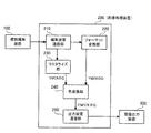
図1は、本実施の形態が適用されるカラー画像処理装置を用いたカラーDTPシステムの一例を示すブロック図である。図1に示すシステムは、電子的な印刷原稿を作成するための原稿編集装置100、本実施の形態が適用されるカラー画像処理を実行する画像処理装置200、カラープリンタ等の画像出力装置300、にて構成されている。
Embodiments of the present invention will be described below in detail with reference to the accompanying drawings.
[Embodiment 1]
FIG. 1 is a block diagram showing an example of a color DTP system using a color image processing apparatus to which the present embodiment is applied. A system shown in FIG. 1 includes an
原稿編集装置100は、ページ記述言語やラスターイメージデータの電子原稿データを画像処理装置200に出力している。より具体的には、原稿編集装置100は、パーソナルコンピュータ(PC)などの汎用のコンピュータ上で各種DTPアプリケーションにより原稿を編集する場合や、専用のコンピュータにより原稿を編集する場合等が考えられる。汎用のコンピュータを使用する場合は、各種のDTPソフトウェアを用いて電子原稿が編集される。作成された電子原稿は、例えばAdobe社のPostScript(登録商標)プリンタドライバによりページ記述言語であるPostScript(登録商標)に変換され、イーサネット(登録商標)などのネットワークによって画像処理装置200に出力される。DTP用パソコンから画像処理装置200に送出する際のページ記述言語としては、PostScript(登録商標)に限られるものではなく、ページ記述言語であればどのようなものでも採用することができる。
The
専用のコンピュータを使用する場合は、CEPS(Color Electric Prepress System)と呼ばれる専用のワークステーションとアプリケーションにより電子原稿を編集することができる。作成された電子原稿は、例えばラスターイメージデータの標準規格であるTIFF(Tagged Image File Format)/ITフォーマットや印刷用の電子データとして広く普及しているScitexフォーマット等のラスター情報の形式で、イーサネット(登録商標)などのネットワークにより画像処理装置200に出力される。勿論、CEPSから画像処理装置200に送出するラスター情報としては、TIFF/ITに限られるものではなく、ラスター形式の画像データであればどのような画像フォーマットを用いても構わない。 When a dedicated computer is used, an electronic manuscript can be edited by a dedicated workstation called CEPS (Color Electric Prepress System) and an application. The created electronic manuscript is, for example, a raster information format such as TIFF (Tagged Image File Format) / IT format, which is a standard of raster image data, or Scitex format which is widely used as electronic data for printing. The image is output to the image processing apparatus 200 via a network such as a registered trademark. Of course, the raster information transmitted from the CEPS to the image processing apparatus 200 is not limited to TIFF / IT, and any image format may be used as long as it is raster format image data.
電子原稿での色信号としては、カラーDTPにおいては出力機器として印刷機を想定することが一般的であり、イエロー、マゼンタ、シアンおよびブラックの所謂YMCK色信号を用いて、電子原稿の色が指定される。また、近年、色域の拡大により、画質向上を狙ったHiFiカラー印刷と呼ばれる5色以上のインクを用いた印刷技術が存在するが、かかる場合は、通常、YMCK色信号に特色としてレッド、グリーンおよびブルーを1色ないし3色加えた5色ないし7色の色信号を用いて、電子原稿が表現される。本実施の形態においては、電子原稿上の色信号として、HiFiカラー印刷の一種であるヘキサクローム印刷を取り上げ、YMCK色信号にオレンジ(O)とグリーン(G)を加えた6色で色再現を行うYMCKOG色信号を用いているが、4色以上の色信号でブラックを含んでいればどのような色信号でも良いことは明らかである。 As a color signal for an electronic document, it is common to assume a printing machine as an output device in color DTP, and the color of the electronic document is designated using so-called YMCK color signals of yellow, magenta, cyan, and black. Is done. Also, in recent years, there is a printing technique using five or more colors of ink called HiFi color printing aimed at improving image quality due to the expansion of the color gamut. In such a case, usually, red, green as special colors for YMCK color signals. And an electronic document is expressed using color signals of 5 to 7 colors obtained by adding 1 to 3 colors of blue. In the present embodiment, hexachrome printing which is a kind of HiFi color printing is taken up as a color signal on an electronic document, and color reproduction is performed with six colors obtained by adding orange (O) and green (G) to the YMCK color signal. Although the YMCKOG color signal to be used is used, it is obvious that any color signal may be used as long as it is black with four or more color signals.
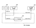
画像処理装置200は、電子原稿を受信する編集装置通信部210、解像度変換やフォーマット変換処理が実行されるフォーマット変換部220、ラスター形式の画像データに変換するラスタライズ部230、入力色信号を出力色信号に変換する色変換部240、および画像記録信号を出力する出力装置通信部250を備えている。そして、画像処理装置200は、これらの各機能を用いて、原稿編集装置100から入力されたコード情報やラスター情報の電子原稿を、画像出力装置300で出力可能な形式に変換して画像出力装置300に出力している。尚、画像処理装置200も原稿編集装置100と同様、PCや専用のコンピュータ、画像出力装置300に搭載されるコンピュータ等の各種コンピュータ装置によって、また、これらによって実行されるプログラムによって実現することができる。
The image processing apparatus 200 includes an editing
原稿編集装置100から送信されるYMCK、YMCKOGおよびYMCKRGB等の色信号で指定された電子原稿は、LAN等のネットワークを介して編集装置通信部210によって受け取られ、フォーマット変換部220およびラスタライズ部230に転送される。ページ記述言語は、ラスタライズ部230によって画像出力装置300で出力可能な形式のラスター形式の画像データに変換される。TIFF/ITのようなラスター形式の画像データは、フォーマット変換部220において解像度変換およびフォーマット変換処理され、画像出力装置300で出力可能な形式であるラスター形式の画像データに変換される。
An electronic document designated by color signals such as YMCK, YMCKOG, and YMCKRGB transmitted from the
ラスタライズ部230およびフォーマット変換部220から転送される、例えばYMCKOG色信号は、色変換部240により、画像出力装置300の画像記録信号であるイエロー、マゼンタ、シアンおよびブラックに、特色としてレッド、グリーンおよびブルーのうちの少なくとも1色を追加した5色ないし7色のHiFiカラーの画像記録信号に変換される。以下の説明では、特色の具体例としてレッド、グリーンの2色を想定し、イエロー、マゼンタ、シアンおよびブラックと共にレッド、グリーンを用いたY′M′C′K′R′G′の6色の画像記録信号に変換されるものとする。勿論、使用する特色はレッド、グリーンに限定されるものではない。
For example, the YMCKOG color signal transferred from the
色変換部240で色変換された画像記録信号は、出力装置通信部250に転送される。出力装置通信部250では、色変換部240までの処理が施された画像記録信号を一旦、メモリ(図示せず)に蓄積し、適宜、画像出力装置300に転送することにより、画像処理装置200と画像出力装置300との処理速度の違いを吸収している。そして、画像出力装置300において、Y′M′C′K′R′G′の6色のラスター形式の画像記録信号に従って、用紙上に画像が形成される。
The image recording signal color-converted by the
画像出力装置300としては、5色以上の色信号で画像を記録するものであればどのような装置でもよい。例えば電子写真方式のカラープリンタ、印刷、インクジェット方式、熱転写方式および銀塩写真方式などのカラー画像出力装置が想定される。その中で、電子写真方式のカラープリンタでは、例えば、所謂タンデム方式を採用する場合に、Y、M、C、Kの4色について各々の画像形成部を備えると共に、例えばRとGの2色の画像形成部を各々備え、これらの例えば6つの画像形成部が中間転写体や転写ベルト上に並んで配置される。そして、例えば、中間転写体上に多重転写されたトナー像が用紙上に一括二次転写され、または、転写ベルト上に搬送される用紙上に順次、トナー像が転写される。この用紙上のトナー像を定着装置において定着することにより、用紙上に例えば6色の色信号で画像が形成される。
The
次に、本実施の形態における特徴的な構成である色変換部240について説明する。
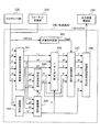
図2は、色変換部240の構成を説明するためのブロック図である。本実施の形態が適用される色変換部240は、入力色信号(第1の色信号)から表色系色座標上の機器独立色信号を決定する機器独立色空間変換部241、入力色信号(第1の色信号)の墨信号から第2の色信号の墨信号を決定する階調補正部242を備えている。また、墨色以外の色信号の状態を判断する非墨色判定部243、機器独立色信号と第2の色信号の墨信号とから、第2の色信号の特色信号を決定する特色量決定部244、入力された墨量K″色信号を補正し、修正された墨量K′色信号を出力する墨量補正部245を備えている。更に、入力された各種色信号からL*a*b*色信号に測色的に等しくなるように第2の色信号のY′M′C′色信号を決定するYMC決定部246、非墨色判定部243からの出力に基づいて非墨色を修正する非墨色修正部247、色変換処理が施された色信号を出力装置通信部250に出力する画像記録信号出力部248を備えている。
Next, the
FIG. 2 is a block diagram for explaining the configuration of the
ラスタライズ部230およびフォーマット変換部220から色変換部240に転送されたYMCKOG色信号は、機器独立色空間変換部241、階調補正部242および非墨色判定部243に入力される。機器独立色空間変換部241では、入力されたYMCKOG色信号から機器独立の色空間であるL*a*b*色信号が決定され、YMC決定部246と特色量決定部244、および墨量補正部245に転送される。階調補正部242では、ラスタライズ部230およびフォーマット変換部220から入力された墨量K色信号と同一またはほぼ同一の明度となる墨量K″色信号が決定され、墨量補正部245に転送される。非墨色判定部243では、入力されたYMCOG色信号が全て零であるか否かが判定され、全て零の場合は、判定信号FlagKが非墨色修正部247に転送される。墨量補正部245では、入力された墨量K″色信号とL*a*b*色信号から、入力された墨量K″色信号が色域内において入力可能である墨量の最大値を超えている場合は最大値に修正し、入力可能である墨量の最小値より小さい場合は最小値に修正した墨量K′色信号が、特色量決定部244、YMC決定部246および画像記録信号出力部248に転送される。
The YMCKOG color signal transferred from the
また、特色量決定部244は、入力されたL*a*b*色信号およびK′信号から、第2の色信号の特色信号が色域内において入力可能である量の最大値および最小値を決定し、この範囲内に、画像出力装置300における特色信号のうちの2色であるR′G′色信号へ変換を行い、YMC決定部246および非墨色修正部247に転送している。YMC決定部246は、入力されたL*a*b*色信号とR′G′色信号、および墨量K′色信号から、L*a*b*色信号に測色的に等しくなるように第2の色信号のY′M′C′色信号を決定し、得られたY′M′C′色信号を非墨色修正部247に転送する。非墨色修正部247では、非墨色判定部243より判定信号FlagKが入力された場合に、Y′M′C′R′G′色信号が零に修正され、画像記録信号出力部248に転送される。画像記録信号出力部248は、非墨色修正部247から入力されるY′M′C′R′G′色信号と墨量補正部245から入力されるK′色信号を出力装置通信部250に転送する。以上により、色変換部240での色変換処理が完了する。
Further, the spot color
次に、各部における処理について、更に具体的に説明する。
まず、機器独立色空間変換部241としては、色変換回路として広く用いられているマトリックス演算型の色変換回路やダイレクトルックアップテーブル型の色変換回路、ニューラルネットワーク型の色変換回路等を使用することが可能である。本実施の形態では、例えば、6入力3出力のニューラルネットワーク型の色変換回路が使用されている。機器独立色空間変換部241の色変換パラメータは、以下に示す方法で決定される。まず、原稿編集装置100から入力されるヘキサクローム印刷の、任意のYMCKOG色信号の組み合わせに対する印刷物の色票を出力し、その測色値(L*a*b*)を市販の測色計で測定する。また、入力するYMCKOG色信号に対応する印刷の測色値(L*a*b*)を求めて、入力データ(YMCKOG)に対する測色値(L*a*b*)の変換特性をモデル化(以後、「色変換モデル」と呼ぶ)する。そのような色変換モデルには、高次多項式やニューラルネットワークが用いられているが、本実施の形態ではニューラルネットワークにYMCKOGデータとL*a*b*データの組み合わせを学習させ、入力されるヘキサクローム印刷の色特性をモデル化した。機器独立色空間変換部241は、求められたニューラルネットワークをそのまま色変換部240に使用した。
Next, the processing in each unit will be described more specifically.
First, as the device-independent color
本実施の形態では、ニューラルネットワークとして、例えば文献「「フレキシブルUCRによる高精度色変換〜ニューラルネットワークによる高精度プリンタモデル〜」、村井和昌著、Japan Hard Copy’94論文集、pp.181−184」に示されているニューラルネットワークを用い、バックプロバケーション法により学習を行っている。この文献における画像記録信号はYMCK4色であるが、ニューラルネットワークにおける1層目の細胞数を4個から6個に増やすことにより、画像記録信号が6色のHiFiカラー用の色変換モデルとして使用することが可能である。勿論、色変換モデルとしてニューラルネットワークを用いる他に、他の多項式モデルや変換テーブル方式の色変換モデルを適用することも可能である。
In the present embodiment, as a neural network, for example, the document “High-precision color conversion by flexible UCR -High-precision printer model by neural network-”, Kazumasa Murai, Japan Hard Copy '94 Proceedings, pp.181-184 Learning is performed by the back pro vacation method using the neural network shown in FIG. The image recording signal in this document is
本実施の形態では、ヘキサクローム印刷における色特性のモデル化に使用した画像記録信号YMCKOGの組み合わせとして、各色の網点面積率が25%刻みの5×5×5×5×5×5=15625個の色票の組み合わせを印刷機で出力し、測色した。この測色は、例えば測色計としてX−Rite社の測色計であるX−Rite938を使用し、測定条件はD50、2度視野のL*a*b*を測定することにより行うことができる。測定に用いる色票の数は、任意の数を使用することが可能であるが、色変換モデルの高精度化のためにできるだけ多い色票数が望ましい。測定に用いた表色系としては、ここでは均等色空間であるL*a*b*表色系を使用したが、XYZ表色系などの他の表色系でも構わない。但し、ニューラルネットワークを学習する際に色差を評価することから、均等色空間が好ましい。 In the present embodiment, as a combination of the image recording signals YMCKOG used for modeling the color characteristics in hexachrome printing, the dot area ratio of each color is 5 × 5 × 5 × 5 × 5 × 5 = 15625 in increments of 25%. The combination of individual color charts was output by a printing press and measured. This color measurement can be performed, for example, by using X-Rite 938, which is a colorimeter manufactured by X-Rite, as the colorimeter, and measuring conditions are D50 and measuring L * a * b * of a two-degree field of view. it can. Any number of color charts can be used for measurement, but as many color charts as possible are desirable in order to increase the accuracy of the color conversion model. Here, the L * a * b * color system, which is a uniform color space, is used as the color system used in the measurement, but other color systems such as an XYZ color system may be used. However, a uniform color space is preferable because color differences are evaluated when learning a neural network.
更に、機器独立色空間変換部241としては、入力する色信号を6色のYMCKOG色信号からなるヘキサクローム印刷に限定するものではなく、墨を含む4色以上の色信号を入力するように構成しても良い。印刷に用いられる墨を含む4色以上の色信号としては、通常広く用いられる4色のYMCK色信号からなるプロセスカラー印刷や、YMCK4色にレッド、グリーンおよびブルーを加えた7色からなるHiFiカラー印刷がある。4色以上の色信号においても、上記と同様な方法により機器独立色空間へ変換することが可能となる。例えば7色の色信号が入力される場合には、7入力3出力のニューラルネットワークを機器独立色空間変換部241に適用すればよい。
Further, the device-independent color
次に、階調補正部242では、1次元のルックアップテーブルを用いて、入力される印刷のK1色の色信号が、等価な明度となる画像出力装置300のK′1色の色信号に変換される。このルックアップテーブルの作成方法としては、印刷と画像出力装置300について、例えば、網点面積率を8ビットに量子化し、それぞれの網点面積率を0から255に変化させたときの明度L*を測定しておき、入力墨量Kの時の明度L*から同じ明度となる出力墨量K′の値を求めてルックアップテーブルの値に設定した。
Next, the
本実施の形態では、高速および高精度に入出力の墨量の階調を補正するために、階調補正部242に1次元のルックアップテーブルを用いたが、関数式等、1次元の入出力関係を記述できるものであればどのようなものでも良く、ルックアップテーブルの量子化分割数も8ビットに限るものではない。また、本実施の形態では、入出力の墨量の明度を一致させるように階調補正部242の変換特性を設定したが、入出力の墨量の濃度を一致させるように変換特性を設定しても構わない。また、入出力の墨量の明度や濃度は一致させることが望ましいが、完全に一致させなくても、ほぼ同等の明度や濃度となるように変換特性を設定することも有効である。
In this embodiment, a one-dimensional lookup table is used for the
ここで、画像出力装置300の色変換モデルの作成方法について説明する。
まず、画像出力装置300における画像記録信号Y′M′C′K′R′G′の任意の組み合わせに対する色パッチを画像出力装置300にてプリントアウトし、測色計を用いてそのときの測色値L*a*b*を測定しておく。本実施の形態では、Y′M′C′K′R′G′の組み合わせとして、各色の網点面積率が25%刻みの5×5×5×5×5×5=15625個のパッチの組み合わせを画像出力装置300でプリントアウトし、測色計はX−Rite社の測色計であるX−Rite938を使用し、測定条件はD50にて、2度視野のL*a*b*を測定した。測定に用いる色パッチの数は任意の数を使用することが可能であるが、色変換モデルの高精度化のために、できるだけ多いパッチ数が望ましい。また、測定に用いた表色系としては、本実施の形態では均等色空間であるL*a*b*表色系を使用したが、XYZ表色系などの他の表色系でも良い。但し、色変換モデルを解く際に色差を評価するため、均等色空間が好ましい。
Here, a method for creating a color conversion model of the
First, a color patch for an arbitrary combination of image recording signals Y′M′C′K′R′G ′ in the
次に、得られた複数のL*a*b*のデータセットを教師データとして、ニューラルネットワークに学習させる。ここでL*a*b*との関係は、次の関数で表すことができる。
(L*a*b*)=F(Y′,M′,C′,K′,R′,G′) …(1)
ここで、(1)式をそれぞれの色成分に分解すると以下のようになる。
L* = FL(Y′,M′,C′,K′,R′,G′) …(2)
a* = Fa(Y′,M′,C′,K′,R′,G′) …(3)
b* = Fb(Y′,M′,C′,K′,R′,G′) …(4)
Next, the neural network is trained by using the obtained data sets of L * a * b * as teacher data. Here, the relationship with L * a * b * can be expressed by the following function.
(L * a * b * ) = F (Y ′, M ′, C ′, K ′, R ′, G ′) (1)
Here, the equation (1) is divided into the respective color components as follows.
L * = FL (Y ′, M ′, C ′, K ′, R ′, G ′) (2)
a * = Fa (Y ′, M ′, C ′, K ′, R ′, G ′) (3)
b * = Fb (Y ′, M ′, C ′, K ′, R ′, G ′) (4)
本実施の形態では、色変換モデルとして使用するニューラルネットワークとして、前述と同じ文献「フレキシブルUCRによる高精度色変換〜ニューラルネットワークによる高精度プリンタモデル〜」に示されているニューラルネットワークを用い、バックプロバケーション法により学習を行った。上記文献における画像記録信号はYMCK4色であるが、ニューラルネットワークにおける1層目の細胞数を4個から6個に増やすことにより、画像記録信号が5色のHiFiカラー用の色変換モデルとして使用することが可能である。本実施の形態では、色変換モデルとしてニューラルネットワークを用いたが、他の多項式モデルや変換テーブル方式の色変換モデルも適用することができる。
In this embodiment, as the neural network used as the color conversion model, the neural network shown in the same document “High-precision color conversion by flexible UCR ~ High-precision printer model by neural network ~” is used, and back processing is performed. We learned by vacation method. The image recording signal in the above document is
次に、色変換モデルの数値解法について説明する。ここで、前述の通常関数Fの逆関数は求まらないが、L*a*b*を与え、Y′M′C′K′R′G′の中の3変数を適切に決定することで、(1)式から残りの3変数を求めることができる。例えば、K′およびR′G′を与えると、Y′M′C′を決定することができる。ここで、再現すべき色をL*a*b*と置き、与える墨量および特色量をK′およびR′G′とすると、再現すべき色と画像記録信号Y′M′C′と墨量K′および特色量R′G′のときの色との色差ΔE*abは、画像記録信号YMCの関数として、次式で定義される。
ΔE*ab(Y′,M′,C′)=
( (L*−FL(Y′,M′,C′,K′,R′,G′))2
+(a*−Fa(Y′,M′,C′,K′,R′,G′))2
+(b*−Fb(Y′,M′,C′,K′,R′,G′))2 )1/2 …(5)
Next, a numerical solution of the color conversion model will be described. Here, although the inverse function of the above-mentioned normal function F cannot be obtained, L * a * b * is given and three variables in Y′M′C′K′R′G ′ are appropriately determined. Thus, the remaining three variables can be obtained from equation (1). For example, given K ′ and R′G ′, Y′M′C ′ can be determined. Here, assuming that the color to be reproduced is L * a * b * and the black amount and the special color amount to be given are K ′ and R′G ′, the color to be reproduced, the image recording signal Y′M′C ′ and the black color. The color difference ΔE * ab from the color when the amount is K ′ and the special color amount R′G ′ is defined by the following equation as a function of the image recording signal YMC.
ΔE * ab (Y ′, M ′, C ′) =
((L * -FL (Y ', M', C ', K', R ', G')) 2
+ (A * −Fa (Y ′, M ′, C ′, K ′, R ′, G ′)) 2
+ (B * −Fb (Y ′, M ′, C ′, K ′, R ′, G ′)) 2 ) 1/2 (5)
非線形方程式である(1)式を解くということは、色差ΔE*abが零になるYMCの値を求めることと同じなので、(1)式を解くという問題を、色差ΔE*abを目的関数とすることによって、目的関数ΔE*abを最小化するYMCを求めるという非線形最適化問題に捉え直すことができる。従って、シンプレックス法などの非線形最適化手法を用いて(1)式を解くことができる。 Solving the non-linear equation (1) is the same as finding the YMC value at which the color difference ΔE * ab becomes zero. Therefore, the problem of solving the equation (1) is solved by using the color difference ΔE * ab as an objective function. By doing so, it can be reinterpreted as a nonlinear optimization problem of obtaining YMC that minimizes the objective function ΔE * ab. Therefore, equation (1) can be solved using a nonlinear optimization method such as the simplex method.
シンプレックス法については、例えば「「非線形計画法」、今野浩著、日科技連出版社、pp.284‐287」にアルゴリズムが紹介されている。シンプレックス法は、このような多変数関数の最適化に適した手法であり、このシンプレックス法を用いることで、高速に最適値を求めることが可能となる。本実施の形態では、非線形最適化手法として多変数関数を高速に最適化可能なシンプレックス法を適用したが、非線形最適化手法であればどのような方法を適用しても良く、2分法や黄金分割探索法などの他の非線形最適化手法を適用しても良い。また、ニュートン法などの非線形方程式の数値解法を適用して色変換モデルを解くこともできる。 As for the simplex method, an algorithm is introduced in, for example, “Nonlinear Programming”, Hiroshi Konno, Nikka Giren Publisher, pp. 284-287. The simplex method is a method suitable for optimizing such a multivariable function. By using this simplex method, it is possible to obtain an optimum value at high speed. In this embodiment, the simplex method capable of optimizing multivariable functions at high speed is applied as the nonlinear optimization method. However, any method may be applied as long as the nonlinear optimization method is used. Other nonlinear optimization methods such as the golden section search method may be applied. In addition, a color conversion model can be solved by applying a numerical solution of a nonlinear equation such as Newton's method.
このように、色変換モデルを解くことにより、L*a*b*色信号と墨量K′および特色量R′G′から、画像出力装置300の墨量がK′色信号および特色量がR′G′色信号であり、かつ入力されるL*a*b*に測色的に一致する画像出力装置300の残りの3色のY′M′C′色信号を決定することができる。また本実施の形態における色変換モデルは、画像出力装置300の色域を分割しないで構成するため、従来技術である分割法で問題となる分割色域境界部における色分解結果の不連続性が原理的に発生せず、擬似輪郭のない滑らかな階調表現が可能となる。
As described above, by solving the color conversion model, the black amount of the
墨量補正部245では、機器独立色空間変換部241から入力されるL*a*b*色信号を再現する場合において、階調補正部242で入力色信号の墨量Kと等しい明度となるように決定された墨量K″が画像出力装置300の色域内で再現可能な値か否かを判定している。この判定により、墨量補正部245は、墨量K″が再現可能な値の最大値よりも大きい場合は、最大値(以後、最大墨量maxKと表記する)に修正し、再現可能な値の最小値(以後、最小墨量minKと表記する)よりも小さい場合は最小値に修正し、特色量決定部244、YMC決定部246および画像記録信号出力部248に墨量K′として転送している。
When the black
墨量補正部245における最大墨量maxKおよび最小墨量minKは、以下のような方法で決定することができる。まず、画像出力装置300の色変換モデルである(1)式において、特色量であるR′信号およびG′信号を零と置くことにより、(1)式はY′M′C′K′の4色の画像形成装置における色変換モデルと等価となる。したがって、機器独立色空間変換部241から入力されるL*a*b*色信号を色変換モデル(1)式に入力し、墨量K′を与えると、残りの3変数であるY′M′C′の色信号を決定することができる。
The maximum black amount maxK and the minimum black amount minK in the black
色変換モデルを解く際には、(5)式により得られたY′M′C′の色信号と入力したK′信号の組み合わせによる色再現と、機器独立色空間変換部241から入力されるL*a*b*色信号との色差ΔE*abが得られる。色差ΔE*abが零になる条件を満たす最も大きい墨量K′が最大墨量maxKであり、最も小さい墨量K′が最少墨量minKである。従って、2分探索法などの数値解法により、(1)式の墨量K′を振って、色差ΔE*abが零となる最大墨量maxKおよび最小墨量minKを求めることが可能である。このように、機器独立色空間変換部241から入力されるL*a*b*色信号を再現する場合において、階調補正部242で決定された墨量K″信号を最大墨量maxKから最小墨量minKまでの範囲の値になるように補正することにより、墨量K′が画像出力装置300の色域内で再現可能な値であることを保証できるので、高い色変換精度を実現することが可能となる。
When solving the color conversion model, color reproduction based on the combination of the Y′M′C ′ color signal obtained by the equation (5) and the input K ′ signal and the device independent color
このように、(1)式において特色量であるR′信号およびG′信号を零とおくことにより、画像出力装置300で得られる色域のうち、大部分の領域を占めるY′M′C′K′の4色の色域における最大墨量maxKおよび最小墨量minKを求めることが可能であり、効率的に最大墨量maxKおよび最小墨量minKを決定することができる。尚、より正確な最大墨量maxKおよび最小墨量minKを決定するために、画像出力装置300のY′M′C′K′R′G′の6色の色域内における最大墨量maxKおよび最小墨量minKを算出するように構成しても良い。かかる場合は、(1)式の墨量K′に加えて特色量R′G′を加えて振ることにより、色差ΔE*abが零になる墨量の最大値と最小値を決定するようにすれば良い。
In this way, by setting the R ′ signal and the G ′ signal, which are the special color amounts, to zero in the equation (1), Y′M′C occupying most of the color gamut obtained by the
また、本実施の形態では、墨量K′信号を最大墨量maxKから最小墨量minKの間の値になるように補正したが、墨量の補正は最大墨量に基づくものだけでも良く、最小墨量による補正を行わないように構成しても良い。このように構成することにより、入力色信号において墨信号が存在しない場合に、確実に出力に墨信号が乗らないようにすることが可能となる。 In the present embodiment, the black amount K ′ signal is corrected to a value between the maximum black amount maxK and the minimum black amount minK. However, the correction of the black amount may be based only on the maximum black amount, You may comprise so that the correction | amendment by minimum black amount may not be performed. With this configuration, it is possible to reliably prevent the black signal from being applied to the output when the black signal does not exist in the input color signal.
このように、墨量補正部245において墨量K′を最大墨量と最小墨量の範囲に補正することにより、高い色変換精度を実現することが可能となるが、入出力における墨量の明度を一致させることを優先する場合には、墨量補正部245による補正処理を行わず、階調補正部242で決定された墨量K″を直接、特色量決定部244に入力するように構成しても良いことは明らかである。
As described above, by correcting the black amount K ′ within the range between the maximum black amount and the minimum black amount by the black
次に、特色量決定部244における特色量R′および特色量G′の決定方法について説明する。前述したように、色変換モデルである(1)式にL*a*b*を与え、Y′M′C′K′R′G′の中の3変数を適切に決めれば、数値解法により残りの3変数を求めることができる。即ち、入力されるL*a*b*色信号に対して、墨量K′および特色量R′G′を決定すれば、残りのY′M′C′を決定することができる。ここで、色変換モデル(1)式を解くときに使用する目的関数(5)式は、入力色信号であるL*a*b*色信号と、画像出力装置300で決定したY′M′C′K′R′G′色信号で色再現させた色との色差を表しており、色差が零の場合は入力色信号が画像出力装置300の色域内であることを表し、色差が零より大きい場合は入力色信号が画像出力装置300の色域外であることを表している。また、墨量K′については墨量補正部245より得られるため、予め設定した特色量R′と特色量G′の組み合わせに対し、目的関数(5)式の色差を判定することにより、その特色量R′と特色量G′の組み合わせが、色域内で再現可能か、不可能かを判定することができる。測色的色再現を保証し、画像出力装置300の色域を最大限使用することが可能な特色量R′および特色量G′を決定するためには、色域内で再現可能な特色量R′と特色量G′の範囲を求めて、その範囲内に特色量R′および特色量G′を設定すれば良い。
Next, a method for determining the spot color amount R ′ and the spot color amount G ′ in the spot color
ここで、色域内で再現可能な特色量R′と特色量G′の範囲の決定方法としては、通常、画像出力装置300の色信号の階調数は256階調程度に量子化されているので、特色量R′と特色量G′の全ての組み合わせを計算しても、256×256=65536通りの色差を(5)式を用いて判定すれば良いと考えられる。
Here, as a method of determining the range of the special color amount R ′ and the special color amount G ′ that can be reproduced in the color gamut, the number of gradations of the color signal of the
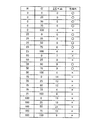
図3は、入力色信号がL*a*b*に対して、特色量R′および特色量G′の全ての組み合わせに対する色差ΔE*abの評価結果のリストの一例を示した図である。ここでは、説明を解り易くするために、階調数を5階調としている。図3のリストでは、特色量R′および特色量G′の組み合わせが色域内のものには○を、色域外のものには×を表示している。また、図3のリストにおいては、特色量決定部244に入力されるL*a*b*色信号が、L*=25、a*=0、b*=0で、墨量K′が零の場合の算出例を表している。
FIG. 3 is a diagram showing an example of a list of evaluation results of the color difference ΔE * ab for all combinations of the special color amount R ′ and the special color amount G ′ with respect to the input color signal L * a * b * . Here, in order to make the explanation easy to understand, the number of gradations is set to 5 gradations. In the list of FIG. 3, a combination of the special color amount R ′ and the special color amount G ′ is displayed when the combination is within the color gamut and is displayed when the combination is outside the color gamut. In the list of FIG. 3, the L * a * b * color signal input to the special color
次に、この図3のリストより、特色量R′と特色量G′の色域内における再現可能範囲を決定する。このとき、まず、決定する色の順番を決める必要がある。ここで、始めに、特色量R′を決定することを考え、特色量R′と特色量G′の組み合わせが色域内で再現可能である場合を、特色量R′の再現可能範囲であると考える。図3のリストを見ると、特色量R′が0%〜50%では色域内のものが存在し、75%および100%では全てが色域外となっている。従って、色域内におけるR′の最小特色量(minR′と表記する)は0%であり、R′の最大特色量(maxR′と表記する)は50%と決定される。このとき、R′の最小特色量を求めず、R′の最小特色量は特色を使わない場合であると考え、minR′=0としても良い。ここで、特色量R′に関する特色入力率をαとおくと、特色量R′は最小特色量と最大特色量の間に決定すれば良いので、特色量R′は次式で決定することができる。
R′=minR′+(maxR′−minR′)×α …(6)
Next, the reproducible range in the color gamut of the special color amount R ′ and the special color amount G ′ is determined from the list of FIG. At this time, it is first necessary to determine the order of colors to be determined. Here, considering that the spot color amount R ′ is first determined, the combination of the spot color amount R ′ and the spot color amount G ′ is reproducible within the color gamut, and the spot color amount R ′ is within the reproducible range. Think. Looking at the list of FIG. 3, when the special color amount R ′ is 0% to 50%, there are those in the color gamut, and 75% and 100% are all out of the color gamut. Therefore, the minimum spot color amount of R ′ (denoted as minR ′) in the color gamut is determined to be 0%, and the maximum spot color amount of R ′ (denoted as maxR ′) is determined to be 50%. At this time, the minimum spot color amount of R ′ is not obtained, and the minimum spot color amount of R ′ may be a case where no spot color is used, and minR ′ = 0 may be set. Here, if the spot color input rate relating to the spot color amount R ′ is α, the spot color amount R ′ may be determined between the minimum spot color amount and the maximum spot color amount. Therefore, the spot color amount R ′ can be determined by the following equation. it can.
R ′ = minR ′ + (maxR′−minR ′) × α (6)
このとき、特色量R′に関する特色入力率αを50%とすると、(6)式より、図3のリストにおける特色量R′は25%と決定される。特色量R′に関する特色入力率αは、このような定率で与える方法に加え、明度や彩度の関数として定義しても良い。即ち、入力色信号であるL*a*b*色信号を入力とした関数により、特色量R′に関する特色入力率αを決定するように構成することもできる。この特色量R′が例えば25%と決定されると、図3のリストより、色差が零になる特色量G′の最小値および最大値が探索される。図3のリストによると、色域内におけるG′の最小特色量(minG′と表記する)は0%であり、G′の最大特色量(maxG′と表記する)は75%と決定される。尚、G′の最小特色量を求めず、最小特色量は特色を加えない場合であると考え、minG′=0としても良い。ここで、特色量G′に関する特色入力率をβとおくと、特色量G′は最小特色量と最大特色量との間に決定すれば良いので、特色量G′は次式で求めることができる。
G′=minG′+(maxG′−minG′)×β …(7)
At this time, if the spot color input rate α for the spot color amount R ′ is 50%, the spot color amount R ′ in the list of FIG. 3 is determined to be 25% from the equation (6). The spot color input rate α relating to the spot color amount R ′ may be defined as a function of brightness or saturation in addition to the method of giving at a constant rate. That is, the spot color input rate α related to the spot color amount R ′ can be determined by a function using the input color signal L * a * b * color signal as an input. When the special color amount R ′ is determined to be 25%, for example, the minimum value and the maximum value of the special color amount G ′ at which the color difference becomes zero are searched from the list of FIG. According to the list of FIG. 3, the minimum spot color amount of G ′ (denoted as minG ′) in the color gamut is determined to be 0%, and the maximum spot color amount of G ′ (denoted as maxG ′) is determined to be 75%. Note that the minimum spot color amount of G ′ is not obtained, and the minimum spot color amount is considered to be a case where no spot color is added, and minG ′ = 0 may be set. Here, if the spot color input rate relating to the spot color amount G ′ is set to β, the spot color amount G ′ may be determined between the minimum spot color amount and the maximum spot color amount. Therefore, the spot color amount G ′ can be obtained by the following equation. it can.
G ′ = minG ′ + (maxG′−minG ′) × β (7)
このとき、特色量G′に関する特色入力率βを50%とすると、(7)式より、図3のリストにおける特色量G′は37.5%と決定される。特色量G′に関する特色入力率βは、このような定率で与える方法に加え、明度や彩度の関数として定義しても良い。即ち、入力色信号であるL*a*b*色信号を入力することにより、特色量G′に関する特色入力率βを決定するようにしても良いことは明らかである。 At this time, if the spot color input rate β for the spot color amount G ′ is 50%, the spot color amount G ′ in the list of FIG. 3 is determined to be 37.5% from the equation (7). The spot color input rate β relating to the spot color amount G ′ may be defined as a function of brightness or saturation in addition to the method of giving at a constant rate. That is, it is obvious that the spot color input rate β related to the spot color amount G ′ may be determined by inputting the L * a * b * color signal that is the input color signal.
尚、図3に示したリストの例においては、最小特色量および最大特色量が求められるが、入力色信号L*a*b*が色域外であると、これらの量が求められない場合がある。かかる場合では、リストにおいて色差が最小となる特色量R′と特色量G′の組み合わせを特色量R′および特色量G′として決定すれば良い。
また、上述の説明では、特色量R′を先に決定してから、次に特色量G′を決定するようにしたが、決定する順番はこれに限るものではなく、先に特色量G′を決定してから、次に特色量R′を決定しても構わない。
更に、本実施の形態では、特色量R′および特色量G′の再現可能範囲を、特色量R′および特色量G′の全ての組み合わせの色差を評価することにより算出したが、再現可能範囲の決定方法はこれに限るものではなく、2分探索アルゴリズムなどによりmaxR′およびminR′とmaxG′およびminG′を効率的に求めても良い。
In the example of the list shown in FIG. 3, the minimum spot color amount and the maximum spot color amount are obtained. However, if the input color signal L * a * b * is out of the color gamut, these amounts may not be obtained. is there. In such a case, a combination of the spot color amount R ′ and the spot color amount G ′ that minimizes the color difference in the list may be determined as the spot color amount R ′ and the spot color amount G ′.
In the above description, the spot color amount R ′ is determined first, and then the spot color amount G ′ is determined. However, the order of determination is not limited to this, and the spot color amount G ′ is determined first. Then, the spot color amount R ′ may be determined next.
Furthermore, in this embodiment, the reproducible range of the special color amount R ′ and the special color amount G ′ is calculated by evaluating the color difference of all combinations of the special color amount R ′ and the special color amount G ′. The determination method is not limited to this, and maxR ′, minR ′, maxG ′, and minG ′ may be efficiently obtained by a binary search algorithm or the like.
また、本実施の形態では、特色量R′および特色量G′を先に決定してから、測色的色再現を保証する残りのY′M′C′色信号を決定するように構成したが、先に決定する色信号は特色量R′および特色量G′に限らない。例えば、Y′およびM′色信号を先に決定してから、特色量R′および特色量G′とC′色信号を決定するように構成することもできる。
更に、本実施の形態では、画像出力装置300の色信号の数として、YMCK4色のプロセスカラーに特色であるレッドおよびグリーンの2色を追加した6色のHiFiカラーの例を示しているが、特色の数はこれに限るものではなく、オレンジのみの5色の場合や、ブルーを追加した7色の場合についても、同様な方法で色変換処理を行えることは明らかである。
In the present embodiment, the special color amount R ′ and the special color amount G ′ are determined first, and then the remaining Y′M′C ′ color signals that guarantee colorimetric color reproduction are determined. However, the color signal determined in advance is not limited to the special color amount R ′ and the special color amount G ′. For example, it may be configured that the Y ′ and M ′ color signals are determined first, and then the special color amount R ′ and the special color amounts G ′ and C ′ color signals are determined.
Furthermore, in the present embodiment, as the number of color signals of the
YMC決定部246においても、上記の方法により色変換モデルを解くことにより、機器独立色空間変換部241から得られるL*a*b*色信号と墨量補正部245から得られる墨量K′、および特色量決定部244から得られる特色量R′G′から、画像出力装置300の墨量がK′、特色量がR′G′であり、且つ、入力されるL*a*b*に測色的に一致する画像出力装置300の、残りの3色のY′M′C′色信号を決定することができ、測色的色再現を保証することが可能である。また、本実施の形態における色変換モデルが画像出力装置300の色域を分割していないため、従来技術である分割法における問題点である擬似輪郭の発生がない。
Also in the
一方、非墨色判定部243では、入力されるYMCOG5色の色信号が同時に零になっているか否かが判定され、判定フラグFlagKが非墨色修正部247に転送される。非墨色修正部247では、非墨色判定部243から判定フラグFlagKを受信した場合に、YMC決定部246および特色量決定部244で得られたY′M′C′R′G′色信号を全て零に修正する。これにより、電子原稿中において墨1色で表現されている黒文字や黒細線を墨1色で表現することができ、黒文字や黒細線の再現性を大幅に向上させることができる。一方、入出力で墨1色になっている部分では、印刷と画像出力装置300との色材の違いや画像構造の違いから、明度を一致させてもY′M′C′R′G′色信号を零に修正することにより若干の色差が生じてしまうが、視覚上問題にならないレベルである。
On the other hand, the non-black
本実施の形態では、非墨色修正部247にて、YMC決定部246および特色量決定部244で得られたY′M′C′R′G′色信号を非墨色判定部243から判定フラグFlagKを受信した場合に、全て零に修正するように構成したが、より入出力での色一致精度を重視する場合は、Y′M′C′R′G′色信号の修正処理を行わないように構成しても良い。但し、黒文字や黒細線の墨1色再現を確実に保証するためには、本実施の形態のように非墨色修正部247におけるY′M′C′R′G′色信号の修正処理を行うように構成したほうが望ましい。
In the present embodiment, the non-black
最後に、画像記録信号出力部248により、画像出力装置300に入力する画像記録信号であるY′M′C′R′G′色信号を出力装置通信部250に転送することで、色変換部240での色変換処理が完了する。
Finally, the image recording
次に、本実施の形態における有効性について説明する。
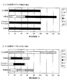
図4(a),(b)は、本実施の形態における評価結果を示した図である。入力する色信号としては、電子原稿における黒文字や黒細線の例として、入力色信号がブラック単色の場合(Kが100%でYMCOGが0%)の色変換結果を図4の(a)に示し、電子原稿における自然画の高明度部から中明度部の例として、入力色信号にブラックがない場合(YMCが50%でKOGが0%)の色変換結果を図4の(b)に示した。それぞれ、入力画像と共に、例えば前述した特許文献3(特開平2001−136401号公報)に代表される分割法をICCに準拠した色変換処理に適用した場合(分割法)、特許文献1(米国特許第4812899号明細書)に代表されるKueppers TequniqueをICCに準拠した色変換処理に適用した場合(Kueppers Tequnique)、色変換部240を本実施の形態のように構成した場合(本実施の形態)が示され、入出力における墨量の一致と、墨1色再現を評価した結果が示されている。本実施の形態以外における色変換部240の構成については、ヘキサクローム印刷のYMCKOG色信号から機器独立のL*a*b*色信号への変換はICCに準拠した公知の6入力3出力のDLUTにより色変換を行っている。また、Kueppers Tequniqueの場合は、公知の3入力3出力DLUTによりL*a*b*色信号からRGB色信号への変換を行い、RGB色信号からY′M′C′K′R′G′色信号への変換は特許文献1の実施例をそのまま適用した。尚、特許文献1においては、UCR率は定義されていないが、アクロマチック成分およびクロマチック成分に関するUCR関数は定率の100%に相当すると考えられる。更に、分割法の場合は、L*a*b*色信号からY′M′C′K′R′G′信号への変換は、特許文献1と近い墨と特色の使用方法とするために、特許文献3の実施例におけるmax Black(墨量が最大となる条件を表す)およびmax HFC(最大特色に相当する)の条件をそのまま適用している。本実施の形態においても、特許文献1と近い特色の使用方法とするために、特色量決定部244で設定するR′およびG′に関する特色入力率として、定率の100%を設定した。
Next, the effectiveness in this embodiment will be described.
4 (a) and 4 (b) are diagrams showing the evaluation results in the present embodiment. As an input color signal, as an example of black characters and black thin lines in an electronic document, the color conversion result when the input color signal is a single black color (K is 100% and YMCOG is 0%) is shown in FIG. FIG. 4B shows the color conversion result when black is not included in the input color signal (YMC is 50% and KOG is 0%) as an example of the high lightness portion to the medium lightness portion of the natural image in the electronic original. It was. When the division method represented by, for example, the above-mentioned Patent Document 3 (Japanese Patent Laid-Open No. 2001-136401) is applied to the color conversion processing based on the ICC (Division Method) together with the input image, Patent Document 1 (US Patent) In the case of applying Kueper's Technique represented by the No. 4812899 specification to color conversion processing conforming to ICC (Kueper's Sequence), when the
図4(a)から明らかなように、本実施の形態では入力色信号がブラック単色の場合に入力画像と等しい墨量が得られ、ブラック単色での再現が可能であるのに対し、従来技術である分割法では、入力画像とほぼ等しい墨量が得られるものの、ブラックの単色再現が不可能であることが解る。また、Kueppers Techniqueにおいても、入力画像とほぼ等しい墨量が得られるものの、僅かながらMとCが乗ってしまっており、ブラックの単色再現が不可能であることが解る。このように、従来技術では、入力色信号がブラック単色の場合に、ブラック単色での再現が不可能であるため、黒文字や黒細線の画質が悪化することが理解できる。 As is clear from FIG. 4A, in the present embodiment, when the input color signal is a single black color, a black amount equivalent to that of the input image can be obtained, and reproduction with a single black color is possible. It can be seen that, with the division method, a black amount almost equal to that of the input image can be obtained, but black monochrome reproduction is impossible. Also, in Kueppers Technique, although a black amount almost equal to that of the input image can be obtained, it is understood that M and C are slightly on board, and black monochrome reproduction is impossible. As described above, in the conventional technique, when the input color signal is a single black color, it is impossible to reproduce with a single black color, so that it can be understood that the image quality of black characters and black thin lines deteriorates.
一方、図4(b)から明らかなように、本実施の形態では入力色信号にブラックがない場合に入力画像と等しい墨量が得られ、墨入れされないのに対し、従来技術であるKueppers Techniqueおよび分割法では、入力画像とは全く異なった墨量となってしまい、墨入れがなされてしまうことが解る。即ち、従来技術では、入力色信号にブラックがない場合に、編集者の意図とは異なった墨入れがなされてしまうため、自然画の粒状性が悪化してしまうことが理解できる。 On the other hand, as is clear from FIG. 4B, in the present embodiment, when the input color signal does not include black, a black amount equal to that of the input image is obtained and is not blacked, whereas Kuepers Technique, which is the prior art. In the division method, the ink amount is completely different from that of the input image, and it is understood that inking is performed. In other words, it can be understood that, in the prior art, when the input color signal does not include black, inking that is different from the intention of the editor is performed, and thus the natural image graininess deteriorates.
このように、本実施の形態では、原稿編集装置100で指定されたYMCKOG6色の色信号から表色系色座標上の機器独立の色空間であるL*a*b*色信号を求め、入力する墨信号Kと同等の明度となる墨量K″信号を決定し、L*a*b*色信号から、墨量K″信号が画像出力装置300での色域内において入力可能である墨量K′信号に補正している。そして、L*a*b*色信号と墨量K′信号から、画像出力装置300での色域内において入力可能である特色R′G′色信号を決定し、入力されたL*a*b*色信号と特色R′G′色信号および墨量K′色信号から、L*a*b*色信号に測色的に等しくなるようにY′M′C′色信号に変換し、墨以外の入力色信号が全て零の場合に、Y′M′C′R′G′色信号を全て零に修正している。これにより、測色的色再現を保証して、高精度な色変換を実現するだけでなく、入力である印刷の墨量と出力であるカラープリンタの墨量とを一致させることが可能となった。また、電子原稿上においてブラック1色で指定された部分はブラック1色で出力することが可能になった。
As described above, in the present embodiment, the L * a * b * color signal, which is a device-independent color space on the color system color coordinates, is obtained from the YMCKOG 6 color signals specified by the
[実施の形態2]
実施の形態1では、図1に示す画像処理装置200の色変換部240を機能ブロックで表現して詳述した。本実施の形態では、色変換部240を6入力6出力のDLUTで構成した例を示している。尚、実施の形態1と同様の機能については同様の符号を用い、ここではその詳細な説明を省略する。
[Embodiment 2]
In the first embodiment, the
図5は、図2に示す色変換部240の各機能ブロックを、DLUT色変換部249にて構成した例を示した図である。図5に示すDLUT色変換部249は、YMCKOG色信号を入力とし、そのYMCKOG色信号に対応するY′M′C′K′R′G′色信号を出力する6次元のダイレクトルックアップテーブル(DLUT)で構成されている。例えば、入力のYMCKOG色信号の各軸を8分割した値を入力アドレスとし、6次元の立方体補間により補間演算を行って画像出力装置300の画像記録信号であるY′M′C′K′R′G′色信号を算出する6次元のDLUTとすることができる。勿論、補間方式としては立方体補間方式に限らず、公知の補間方式であれば三角柱補間や四面体補間などの他の方式を適用しても良い。また、入力の各軸の分割数も8分割に限るものではない。
FIG. 5 is a diagram illustrating an example in which each functional block of the
ここでは、色変換部240を6次元のダイレクトルックアップテーブル(DLUT)にて構成したが、6入力6出力の色変換が行えればこれに限られるわけではなく、ニューラルネットワークなどの公知の色変換方式であれば他の色変換方式を適用しても良い。更に、色変換部240に入力する色信号は、ヘキサクローム印刷のYMCKOG色信号に限定されるものではなく、プロセスカラー印刷のYMCK色信号やHiFiカラー印刷のYMCKRGB色信号など、墨を含んだ4色以上の色信号であれば構わない。DLUT色変換部249の次元数は、入力される色信号の数と一致するため、例えば入力色信号がプロセスカラー印刷のYMCK色信号の場合は、4次元のDLUTが必要であり、入力色信号がHiFiカラー印刷のYMCKRGB色信号の場合では、7次元のDLUTが必要であることは明らかである。
Here, the
次に、色変換部240を構成するDLUT色変換部249による処理について説明する。
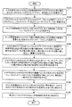
図6は、DLUT色変換部249における色変換パラメータ決定処理の一例を示すフローチャートである。尚、この処理は、図2に示す実施の形態1における色変換部240の各部で行う処理とほぼ同様である。
まず、ヘキサクローム印刷の入力色信号であるYMCKOG色信号、および画像出力装置300の画像記録信号Y′M′C′K′R′G′の任意の組み合わせに対する色票(色パッチ)を、ヘキサクローム印刷および画像出力装置300にてプリントアウトし、測色計を用いてその時の測色値L*a*b*を測定する(ステップ101)。ヘキサクローム印刷のYMCKOG色信号と画像出力装置300の画像記録信号Y′M′C′K′R′G′の組み合わせおよび測色条件は、上述した実施の形態1と同様で構わない。
Next, processing by the DLUT
FIG. 6 is a flowchart illustrating an example of color conversion parameter determination processing in the DLUT
First, a color chart (color patch) for an arbitrary combination of a YMCKOG color signal that is an input color signal for hexachrome printing and an image recording signal Y′M′C′K′R′G ′ of the
次に、ステップ101で得られた複数のYMCKOGおよびY′M′C′K′R′G′とL*a*b*のデータセットを教師データとして、色変換モデルであるニューラルネットワーク1およびニューラルネットワーク2にそれぞれ学習させる(ステップ102)。ニューラルネットワークは、上述した実施の形態1と同様のもので良い。その後、DLUT色変換部249の入力アドレス値YMCKOGに対する測色値を表すL*a*b*色信号をニューラルネットワーク1により決定する(ステップ103)。そして、DLUT色変換部249の入力アドレス値Kと等価な明度になる画像出力装置300の墨量K″を1次元のルックアップテーブルにより決定する(ステップ104)。この1次元のルックアップテーブルの決定方法についても、上述した実施の形態1と同様のものを用いることができる。
Next, using a plurality of YMCKOG and Y′M′C′K′R′G ′ and L * a * b * data sets obtained in step 101 as teacher data, the neural network 1 and the neural network 1 which are color conversion models Each of the networks 2 learns (step 102). The neural network may be the same as that in the first embodiment. Thereafter, the neural network 1 determines an L * a * b * color signal representing a colorimetric value for the input address value YMCKOOG of the DLUT color conversion unit 249 (step 103). Then, the black amount K ″ of the
その後、ステップ103で求めたL*a*b*色信号をニューラルネットワーク2に入力し、画像出力装置300の色域内で色再現可能な墨量の最大値および最小値を求め、ステップ104で求めた墨量K″が最大値を超えていれば最大値に修正し、最小値より小さければ最小値に修正して墨量K′を決定する(ステップ105)。墨量の最大値および最小値の決定方法についても、上述した実施の形態1と同様で構わない。そして、ステップ103で求めたL*a*b*色信号と、ステップ105で求めた墨量K′をニューラルネットワーク2に入力して、画像出力装置300の色域内で色再現可能なR′G′色信号の最大値および最小値を求め、R′G′色信号をこの最大値から最小値の間となるように決定する(ステップ106)。尚、R′G′色信号の決定方法についても、上述した実施の形態1と同様で良い。
Thereafter, the L * a * b * color signal obtained in step 103 is input to the neural network 2, and the maximum and minimum black quantities that can be reproduced in the color gamut of the
次に、ステップ103で求めたL*a*b*信号と、ステップ105で求めた墨量K′、およびステップ106で求めたR′G′色信号をニューラルネットワーク2に入力して数値解法で解くことにより、測色的に一致するY′M′C′色信号が求められる(ステップ107)。このY′M′C′色信号の数値解法についても、上述した実施の形態1と同様のものを用いることができる。その後、DLUT色変換部249の入力アドレス値YMCOGが全て零の場合に、ステップ107で求められたY′M′C′色信号とステップ106で求められたR′G′色信号とが、全て零に修正される(ステップ108)。そして、最後に、得られたY′M′C′K′R′G′をDLUT色変換部249の格子点に設定することにより(ステップ109)、DLUT色変換部249の色変換パラメータを決定することができる。
Next, the L * a * b * signal obtained in step 103, the black amount K ′ obtained in step 105, and the R′G ′ color signal obtained in step 106 are input to the neural network 2 and numerically solved. By solving, a Y'M'C 'color signal that coincides colorimetrically is obtained (step 107). Also for the numerical solution of the Y′M′C ′ color signal, the same one as in the first embodiment can be used. Thereafter, when the input address values YMCOG of the DLUT
以上のようにしてDLUT色変換部249の色変換パラメータがあらかじめ決定される。尚、DLUT色変換部249に設定されるものは、例えば入力のYMCKOG色信号の各軸を8分割した格子点におけるY′M′C′K′R′G′の値である。実際に入力されるYMCKOG色信号は格子点に限らず、任意のYMCKOG色信号が入力される。従って、色変換処理を行う際には、入力されたYMCKOG色信号に基づいて1ないし複数の格子点のアドレスを生成してY′M′C′K′R′G′の値を読み出し、補間処理を行うことによって、入力されたYMCKOG色信号に対応するY′M′C′K′R′G′色信号を得ることになる。
As described above, the color conversion parameters of the DLUT
このように実施の形態2では、実施の形態1で示した構成のように色変換部240で色変換処理を行う際に演算量の多い処理を行わずに、予め作成しておいたダイレクトルックアップテーブルで直接色変換することから、非常に高速な色変換を実現することが可能になる。また、ハードウェアで構成した場合、演算量が少ないことから、簡易な構成とすることができる。
As described above, in the second embodiment, a direct look created in advance without performing a process with a large amount of calculation when the
以上、本実施の形態(実施の形態1および実施の形態2)では、実施の形態1に例示するように、例えば、墨を含む4色以上からなる第1の色信号から表色系色座標上の機器独立色信号を求め、第1の色信号の墨信号とほぼ同等の明度となる第2の色信号の墨信号を決定し、決定された機器独立色信号と第2の色信号の墨信号から第2の色信号の特色信号を決定し、決定された機器独立色信号と第2の色信号の墨信号および特色信号から第2の色信号のYMC色信号を機器独立色信号と測色的に等しくなるように決定した。これにより、HiFiカラーのための色変換処理として、測色的色再現を実現することに加えて、入出力の墨量を一致させることが可能となった。特に、従来技術であるKueppers Techniqueや分割法をICCに準拠した色変換に適用した場合では、入力色信号となるYMCK色信号やYMCKOG色信号など機器依存の色空間から、L*a*b*やXYZ色空間のような機器独立色信号に変換を行った際に、入力色信号の墨情報が保持されないので、カラープリンタの5色ないし7色の画像記録信号に変換した際の出力の墨量は入力色信号の墨量と異なってしまうといった問題があった。しかしながら、本実施の形態によれば、入力色信号の墨信号から同一またはほぼ同一の明度となるカラープリンタの墨信号を1次元のルックアップテーブルで直接決定しているため、入出力の墨量を一致させることが可能であり、電子原稿を作成する編集者によって指定される墨量を忠実に再現したプリントを得ることが可能である。 As described above, in the present embodiment (Embodiment 1 and Embodiment 2), as exemplified in Embodiment 1, for example, the color coordinate system color coordinates are obtained from the first color signal composed of four or more colors including black. The upper device independent color signal is obtained, the black signal of the second color signal having a lightness substantially equal to the black signal of the first color signal is determined, and the determined device independent color signal and the second color signal are determined. The spot color signal of the second color signal is determined from the black signal, and the determined device independent color signal and the YMC color signal of the second color signal from the black signal and the spot color signal of the second color signal are defined as the device independent color signal. It was determined to be colorimetrically equal. As a result, in addition to realizing colorimetric color reproduction as color conversion processing for the HiFi color, it is possible to match the input and output black amounts. In particular, when the conventional technique Kepper's Technique and the division method are applied to color conversion based on ICC, L * a * b * is determined from a device-dependent color space such as a YMCK color signal or a YMCKOG color signal as an input color signal . Since the black information of the input color signal is not retained when it is converted to a device independent color signal such as the XYZ color space, the black color of the output when converted to an image recording signal of 5 to 7 colors of the color printer There is a problem that the amount differs from the black amount of the input color signal. However, according to the present embodiment, since the black signal of the color printer having the same or almost the same lightness is directly determined from the black signal of the input color signal by the one-dimensional lookup table, the input / output black amount is determined. Can be matched, and a print that faithfully reproduces the amount of black specified by the editor who creates the electronic document can be obtained.
更に、第1の色信号の墨信号とほぼ同等の明度となる第2の色信号の墨信号を画像出力装置の色域内において入力可能な墨量の最大値を超えている場合は最大値に修正し、最小値より小さい場合は最小値に修正した。これにより、高精度な色変換を実現することが可能である。また、機器独立色信号から第2の色信号の特色信号に関するUCR率と第2の色信号の特色信号が画像出力装置の色域内において入力可能な最大値および最小値から、第2の色信号の特色信号が画像出力装置の色域内においてこの最大値から最小値の間になるように決定した。これにより、高精度な色変換を実現することが可能である。更に、第1の色信号における墨以外の色信号が零の場合に第2の色信号における墨以外の色信号を零と設定することにより、電子原稿中においてブラック1色で指定されている部分はブラック1色で出力することが可能となり、黒文字や黒細線の良好な再現を実現することが可能となった。 Further, when the black signal of the second color signal having lightness substantially equal to that of the black signal of the first color signal exceeds the maximum black amount that can be input in the color gamut of the image output apparatus, the maximum value is set. It was corrected, and when it was smaller than the minimum value, it was corrected to the minimum value. Thereby, highly accurate color conversion can be realized. Further, the second color signal is obtained from the maximum value and the minimum value at which the UCR rate relating to the special color signal of the second color signal from the device independent color signal and the special color signal of the second color signal can be input within the color gamut of the image output device. The special color signal is determined to be between the maximum value and the minimum value in the color gamut of the image output apparatus. Thereby, highly accurate color conversion can be realized. Further, when the color signal other than black in the first color signal is zero, the color signal other than black in the second color signal is set to zero, so that the portion designated by one black color in the electronic document Can be output in one black color, and it has become possible to achieve good reproduction of black characters and black thin lines.
また、実施の形態2に示すように、演算量の多い色変換処理を予め行ってDLUTの色変換パラメータを決定しておき、そのようなDLUTで直接色変換するように構成することができる。これによって、実際の色変換処理時には非常に高速な色変換を実現することが可能になる。また、ハードウェアで本発明を実現した場合、演算量が少ないために簡易なハードウェアで実現することができる。 Further, as shown in the second embodiment, it is possible to perform color conversion processing with a large amount of calculation in advance to determine the color conversion parameters of the DLUT, and to perform direct color conversion using such a DLUT. This makes it possible to realize very high-speed color conversion during actual color conversion processing. Further, when the present invention is realized by hardware, since the amount of calculation is small, it can be realized by simple hardware.
尚、上述した本実施の形態の各機能は、例えばカラー画像形成装置が有するコンピュータ装置や、カラー画像形成装置に接続されて画像処理を行うPC等、各種のコンピュータ装置にて実行されるコンピュータプログラムとして実現することができる。即ち、本実施の形態で説明した色変換部240の機能や、図1に示した色変換部240以外の画像処理装置200における各機能の一部または全部を、コンピュータにより実行可能なプログラムによって実現することが可能である。このプログラムは、磁気ディスクや光ディスク、光磁気ディスク等の各種記憶媒体に格納され、アプリケーションプログラムとしてコンピュータ装置の主記憶装置に読み出されてCPUにより実行され、上述した各機能が実現される。また、このプログラムの提供は、予めコンピュータ装置の各種記憶媒体に格納された状態で提供される場合の他、CD−ROMや各種DVD、メモリカード、フラッシュROM等の可搬性の記憶媒体に格納された状態で提供される場合がある。また、インターネット等のネットワークを介して、遠隔地にあるプログラム電送装置から提供される形態も考えられる。勿論、一部の機能についてハードウェアによって構成することもできるし、あるいは、全てをハードウェアで構成してもよい。また、図1に示した原稿編集装置100の構成も含めたプログラムとして構成したり、あるいは画像出力装置300における制御プログラムと共に1つのプログラムとして構成することもできる。勿論、他の用途に適用する場合には、その用途におけるプログラムとの一体化も可能である。
Each function of the above-described embodiment is a computer program executed by various computer apparatuses such as a computer apparatus included in the color image forming apparatus or a PC connected to the color image forming apparatus to perform image processing. Can be realized. That is, some or all of the functions of the
本発明の活用例としては、カラー画像形成装置が有するコンピュータ装置、カラー画像形成装置に接続されて画像処理を行うコンピュータ装置、パーソナルコンピュータ(PC)等にて実現する例が挙げられる。 Examples of use of the present invention include a computer apparatus included in a color image forming apparatus, a computer apparatus connected to the color image forming apparatus and performing image processing, a personal computer (PC), and the like.
100…原稿編集装置、200…画像処理装置、210…編集装置通信部、220…フォーマット変換部、230…ラスタライズ部、240…色変換部、241…機器独立色空間変換部、242…階調補正部、243…非墨色判定部、244…特色量決定部、245…墨量補正部、246…YMC決定部、247…非墨色修正部、248…画像記録信号出力部、249…DLUT色変換部、250…出力装置通信部、300…画像出力装置
DESCRIPTION OF
Claims (18)
前記第1の色信号における墨信号と同一またはほぼ同一の明度となる前記第2の色信号の墨信号を出力する墨信号出力手段と、
前記第1の色信号における表色系色座標上の機器独立色信号と測色的に等しくなるように、前記第2の色信号の特色信号とYMC色信号とを出力する色信号出力手段と
を含むカラー画像処理装置。 Input a first color signal consisting of four or more colors including black, and from five to seven colors, which are black and yellow (Y), magenta (M) and cyan (C) plus one to three special colors In a color image processing apparatus for converting and outputting the second color signal,
A black signal output means for outputting a black signal of the second color signal having the same or substantially the same brightness as the black signal in the first color signal;
Color signal output means for outputting the special color signal of the second color signal and the YMC color signal so as to be colorimetrically equal to the device independent color signal on the color system color coordinates in the first color signal. A color image processing apparatus.
前記色信号出力手段は、前記機器独立色信号決定手段により決定された前記機器独立色信号と前記第2の色信号の墨信号から当該第2の色信号における前記特色信号を決定し、当該機器独立色信号と当該墨信号および当該特色信号から当該第2の色信号における前記YMC色信号を決定することを特徴とする請求項1記載のカラー画像処理装置。 Device-independent color signal determining means for determining the device-independent color signal on the color system color coordinates from the first color signal;
The color signal output unit determines the spot color signal in the second color signal from the device independent color signal determined by the device independent color signal determination unit and the black signal of the second color signal, and the device 2. The color image processing apparatus according to claim 1, wherein the YMC color signal in the second color signal is determined from the independent color signal, the black signal, and the special color signal.
前記第1の色信号から表色系色座標上の機器独立色信号を決定する第1の変換手段と、
前記第1の色信号における墨信号と同一またはほぼ同一の明度となる前記第2の色信号の墨信号を決定する第2の変換手段と、
前記第1の変換手段により決定された前記機器独立色信号と前記第2の変換手段により決定された前記第2の色信号の墨信号から、当該第2の色信号の特色信号を決定する第3の変換手段と、
前記第1の変換手段により決定された前記機器独立色信号、前記第2の変換手段により決定された前記第2の色信号の墨信号、および前記第3の変換手段により決定された当該第2の色信号の特色信号から、当該機器独立色信号と測色的に等しくなるように当該第2の色信号のYMC色信号を決定する第4の変換手段と
を含むカラー画像処理装置。 A first color signal composed of four or more colors including black is obtained by adding five to seven colors including black and yellow (Y), magenta (M) and cyan (C) plus one to three special colors. In a color image processing apparatus for converting to a color signal of 2,
First conversion means for determining a device independent color signal on a color system color coordinate from the first color signal;
Second conversion means for determining a black signal of the second color signal having the same or substantially the same lightness as the black signal in the first color signal;
A spot color signal of the second color signal is determined from the device independent color signal determined by the first conversion means and the black signal of the second color signal determined by the second conversion means. 3 conversion means;
The device independent color signal determined by the first conversion means, the black signal of the second color signal determined by the second conversion means, and the second color determined by the third conversion means. And a fourth conversion means for determining a YMC color signal of the second color signal so as to be colorimetrically equal to the device independent color signal from the spot color signal of the color signal.
前記第1の色信号における墨以外の色信号が零の場合に、前記第2の色信号における墨以外の色信号を零に設定し、
前記第1の色信号に墨信号がない場合に、前記第2の色信号に墨信号を含めず、特色信号とYMC色信号との両者を用いて当該第2の色信号を設定することを特徴とするカラー画像処理方法。 A first color signal composed of four or more colors including black is obtained by adding five to seven colors including black and yellow (Y), magenta (M) and cyan (C) plus one to three special colors. In a color image processing method of converting to a color signal of 2,
When the color signal other than black in the first color signal is zero, the color signal other than black in the second color signal is set to zero;
When the black signal is not included in the first color signal, the black signal is not included in the second color signal, and the second color signal is set using both the special color signal and the YMC color signal. A characteristic color image processing method.
前記第1の色信号から表色系色座標上の機器独立色信号を決定するステップと、
前記第1の色信号の墨信号と同一またはほぼ同一の明度となる前記第2の色信号の墨信号を決定するステップと、
決定された前記機器独立色信号と前記第2の色信号の墨信号から当該第2の色信号の特色信号を決定するステップと、
前記機器独立色信号と前記第2の色信号の特色信号および墨信号から当該第2の色信号のYMC色信号を当該機器独立色信号と測色的に等しくなるように決定するステップと
を含むカラー画像処理方法。 A first color signal composed of four or more colors including black is obtained by adding five to seven colors including black and yellow (Y), magenta (M) and cyan (C) plus one to three special colors. In a color image processing method of converting to a color signal of 2,
Determining a device independent color signal on a color system color coordinate from the first color signal;
Determining a black signal of the second color signal having the same or substantially the same brightness as the black signal of the first color signal;
Determining the spot color signal of the second color signal from the determined device independent color signal and the black signal of the second color signal;
Determining the YMC color signal of the second color signal to be colorimetrically equal to the device independent color signal from the device independent color signal, the spot color signal of the second color signal, and the black signal. Color image processing method.
決定された前記第2の色信号の墨信号が色域内において入力可能である墨量の最大値を超えている場合は最大値に修正し、色域内において入力可能である墨量の最小値より小さい場合は最小値に修正するステップとを更に備えたことを特徴とする請求項12記載のカラー画像処理方法。 Setting the non-black color signal in the second color signal to zero when the non-black color signal in the first color signal is zero;
When the determined black signal of the second color signal exceeds the maximum black amount that can be input within the color gamut, the black value is corrected to the maximum value, and the minimum black amount that can be input within the color gamut 13. The color image processing method according to claim 12, further comprising a step of correcting to a minimum value when the value is smaller.
墨を含む4色以上からなる第1の色信号における墨以外の色信号が零の場合に、墨とイエロー(Y)、マゼンタ(M)およびシアン(C)に1色ないし3色の特色を加えた5色ないし7色からなる第2の色信号における墨以外の色信号を零に設定する機能と、
前記第1の色信号に墨信号がない場合に、前記第2の色信号に墨信号を含めず、特色信号とYMC色信号との両者を用いて当該第2の色信号を設定する機能と
を実現させるプログラム。 On the computer,
When the color signal other than black in the first color signal consisting of four or more colors including black is zero, one or three special colors are added to black and yellow (Y), magenta (M), and cyan (C). A function for setting a color signal other than black in the second color signal of five to seven colors added to zero;
A function of setting the second color signal using both the spot color signal and the YMC color signal without including the black signal in the second color signal when the first color signal does not include the black signal; A program that realizes
前記第2の色信号を設定する機能は、前記特色信号および前記YMC色信号の所定数の色信号が、決定された前記機器独立色信号と測色的に等しくなるように当該特色信号および/または当該YMC色信号を設定することを特徴とする請求項15記載のプログラム。 Allowing the computer to further realize a function of determining a device independent color signal on the color system color coordinates obtained from the first color signal;
The function of setting the second color signal is such that the predetermined number of color signals of the spot color signal and the YMC color signal are colorimetrically equal to the determined device independent color signal and / or The program according to claim 15, wherein the YMC color signal is set.
墨を含む4色以上からなる第1の色信号から表色系色座標上の機器独立色信号を決定する機能と、
墨とイエロー(Y)、マゼンタ(M)およびシアン(C)に1色ないし3色の特色を加えた5色ないし7色からなる第2の色信号における墨信号を、前記第1の色信号の墨信号と同一またはほぼ同一の明度となるように決定する機能と、
決定された前記機器独立色信号と前記第2の色信号の墨信号から当該第2の色信号の特色信号を決定する機能と、
前記機器独立色信号と前記第2の色信号の特色信号および墨信号から当該第2の色信号のYMC色信号を当該機器独立色信号と測色的に等しくなるように決定する機能と
を実現させるプログラム。 On the computer,
A function for determining a device-independent color signal on a color system color coordinate from a first color signal including four or more colors including black;
The black signal in the second color signal consisting of five to seven colors obtained by adding one or three special colors to black and yellow (Y), magenta (M) and cyan (C) is the first color signal. A function to determine the same or almost the same brightness as the black signal of
A function of determining the spot color signal of the second color signal from the determined device independent color signal and the black signal of the second color signal;
A function for determining the YMC color signal of the second color signal to be colorimetrically equal to the device independent color signal from the device independent color signal, the special color signal of the second color signal and the black signal. Program to make.
前記第1の色信号における墨以外の色信号が零の場合に前記第2の色信号における墨以外の色信号を零に設定する機能と、
決定された前記第2の色信号の墨信号が色域内において入力可能である墨量の最大値を超えている場合は最大値に修正し、色域内において入力可能である墨量の最小値より小さい場合は最小値に修正する機能とを更に実現させる請求項17記載のプログラム。 In the computer,
A function for setting a color signal other than black in the second color signal to zero when a color signal other than black in the first color signal is zero;
When the determined black signal of the second color signal exceeds the maximum black amount that can be input within the color gamut, the black value is corrected to the maximum value, and the minimum black amount that can be input within the color gamut The program according to claim 17, further realizing a function of correcting to a minimum value when it is small.
Priority Applications (1)
| Application Number | Priority Date | Filing Date | Title |
|---|---|---|---|
| JP2003355213A JP2005123797A (en) | 2003-10-15 | 2003-10-15 | Color image processing apparatus, color image processing method, and program |
Applications Claiming Priority (1)
| Application Number | Priority Date | Filing Date | Title |
|---|---|---|---|
| JP2003355213A JP2005123797A (en) | 2003-10-15 | 2003-10-15 | Color image processing apparatus, color image processing method, and program |
Publications (1)
| Publication Number | Publication Date |
|---|---|
| JP2005123797A true JP2005123797A (en) | 2005-05-12 |
Family
ID=34612887
Family Applications (1)
| Application Number | Title | Priority Date | Filing Date |
|---|---|---|---|
| JP2003355213A Pending JP2005123797A (en) | 2003-10-15 | 2003-10-15 | Color image processing apparatus, color image processing method, and program |
Country Status (1)
| Country | Link |
|---|---|
| JP (1) | JP2005123797A (en) |
Cited By (2)
| Publication number | Priority date | Publication date | Assignee | Title |
|---|---|---|---|---|
| JP2011009843A (en) * | 2009-06-23 | 2011-01-13 | Fuji Xerox Co Ltd | Color processor, and color processing program |
| CN102158731A (en) * | 2011-05-26 | 2011-08-17 | 威盛电子股份有限公司 | Image processing system and method |
-
2003
- 2003-10-15 JP JP2003355213A patent/JP2005123797A/en active Pending
Cited By (2)
| Publication number | Priority date | Publication date | Assignee | Title |
|---|---|---|---|---|
| JP2011009843A (en) * | 2009-06-23 | 2011-01-13 | Fuji Xerox Co Ltd | Color processor, and color processing program |
| CN102158731A (en) * | 2011-05-26 | 2011-08-17 | 威盛电子股份有限公司 | Image processing system and method |
Similar Documents
| Publication | Publication Date | Title |
|---|---|---|
| JP4238992B2 (en) | Color image processing method, color image processing apparatus, color image processing program, and storage medium | |
| US7199900B2 (en) | Color conversion coefficient preparation apparatus, color conversion coefficient preparation method, storage medium, and color conversion system | |
| JP3249693B2 (en) | Image processing device | |
| JP4206743B2 (en) | Color image processing method, color image processing apparatus, color image processing program, and storage medium | |
| JP5354875B2 (en) | Color processing apparatus and color processing method | |
| US6072901A (en) | System and method for deriving an invertible relationship between color spaces where the intrinsic mapping is one-to-many for use in a color profile production system | |
| JPH08102865A (en) | Method and device for deciding color conversion coefficient | |
| US20080278736A1 (en) | Image processing apparatus and method, image output apparatus, image processing system, recording medium in which image processing program is stored, and recording medium in which image output program is stored | |
| US7580150B2 (en) | System and method for reproducing colors on a printing device | |
| JP4471021B2 (en) | Color printing control apparatus, color printing control method, and color printing control program | |
| JP2005176280A (en) | Color image processing method, color image processing apparatus, color image processing program, and storage medium | |
| JP6155644B2 (en) | Image processing apparatus, image processing method, program, and storage medium | |
| JP4518408B2 (en) | Image processing apparatus, method, and program | |
| JP4646567B2 (en) | Color conversion table creation method and image processing apparatus | |
| JP4228207B2 (en) | Color image processing method, color image processing apparatus, color image processing program, and storage medium | |
| JP4228208B2 (en) | Color image processing method, color image processing apparatus, color image processing program, and storage medium | |
| JP4506948B2 (en) | Color conversion coefficient creation method, color conversion coefficient creation apparatus, color conversion coefficient creation program, and storage medium | |
| JP2001111862A (en) | Image processing method and image processing system | |
| US7436416B2 (en) | Color printer and control method thereof with pulse width modulation for tone control based on type of document and number of colors printed | |
| JP2002152543A (en) | Apparatus and method of generating color conversion coefficients, storing medium and color conversion system | |
| JP2005123797A (en) | Color image processing apparatus, color image processing method, and program | |
| JP4062397B2 (en) | Image processing apparatus, color conversion definition generation apparatus, image processing method, color conversion definition generation method, storage medium | |
| JP3790204B2 (en) | Color image processing apparatus and color image processing method | |
| JP2011151491A (en) | Device and program for color conversion | |
| JP4793364B2 (en) | Color processing apparatus, image forming apparatus, and program |