JP2005104258A - Electrical instrument holder for bicycle - Google Patents
Electrical instrument holder for bicycle Download PDFInfo
- Publication number
- JP2005104258A JP2005104258A JP2003339134A JP2003339134A JP2005104258A JP 2005104258 A JP2005104258 A JP 2005104258A JP 2003339134 A JP2003339134 A JP 2003339134A JP 2003339134 A JP2003339134 A JP 2003339134A JP 2005104258 A JP2005104258 A JP 2005104258A
- Authority
- JP
- Japan
- Prior art keywords
- electrical component
- bicycle
- dynamo
- output
- housing
- Prior art date
- Legal status (The legal status is an assumption and is not a legal conclusion. Google has not performed a legal analysis and makes no representation as to the accuracy of the status listed.)
- Pending
Links
- LTMHDMANZUZIPE-PUGKRICDSA-N digoxin Chemical compound C1[C@H](O)[C@H](O)[C@@H](C)O[C@H]1O[C@@H]1[C@@H](C)O[C@@H](O[C@@H]2[C@H](O[C@@H](O[C@@H]3C[C@@H]4[C@]([C@@H]5[C@H]([C@]6(CC[C@@H]([C@@]6(C)[C@H](O)C5)C=5COC(=O)C=5)O)CC4)(C)CC3)C[C@@H]2O)C)C[C@@H]1O LTMHDMANZUZIPE-PUGKRICDSA-N 0.000 abstract description 3
- 238000007493 shaping process Methods 0.000 description 16
- 230000005540 biological transmission Effects 0.000 description 11
- 239000000725 suspension Substances 0.000 description 9
- 239000004973 liquid crystal related substance Substances 0.000 description 8
- 239000003990 capacitor Substances 0.000 description 6
- 230000001413 cellular effect Effects 0.000 description 4
- HBBGRARXTFLTSG-UHFFFAOYSA-N Lithium ion Chemical compound [Li+] HBBGRARXTFLTSG-UHFFFAOYSA-N 0.000 description 3
- OJIJEKBXJYRIBZ-UHFFFAOYSA-N cadmium nickel Chemical compound [Ni].[Cd] OJIJEKBXJYRIBZ-UHFFFAOYSA-N 0.000 description 3
- 229910001416 lithium ion Inorganic materials 0.000 description 3
- 229910052987 metal hydride Inorganic materials 0.000 description 3
- 238000000034 method Methods 0.000 description 3
- 229910052759 nickel Inorganic materials 0.000 description 3
- PXHVJJICTQNCMI-UHFFFAOYSA-N nickel Substances [Ni] PXHVJJICTQNCMI-UHFFFAOYSA-N 0.000 description 3
- -1 nickel metal hydride Chemical class 0.000 description 3
- 238000010586 diagram Methods 0.000 description 1
- 230000005611 electricity Effects 0.000 description 1
- 238000003466 welding Methods 0.000 description 1
Images


Classifications
-
- F—MECHANICAL ENGINEERING; LIGHTING; HEATING; WEAPONS; BLASTING
- F03—MACHINES OR ENGINES FOR LIQUIDS; WIND, SPRING, OR WEIGHT MOTORS; PRODUCING MECHANICAL POWER OR A REACTIVE PROPULSIVE THRUST, NOT OTHERWISE PROVIDED FOR
- F03G—SPRING, WEIGHT, INERTIA OR LIKE MOTORS; MECHANICAL-POWER PRODUCING DEVICES OR MECHANISMS, NOT OTHERWISE PROVIDED FOR OR USING ENERGY SOURCES NOT OTHERWISE PROVIDED FOR
- F03G7/00—Mechanical-power-producing mechanisms, not otherwise provided for or using energy sources not otherwise provided for
- F03G7/08—Mechanical-power-producing mechanisms, not otherwise provided for or using energy sources not otherwise provided for recovering energy derived from swinging, rolling, pitching or like movements, e.g. from the vibrations of a machine
-
- B—PERFORMING OPERATIONS; TRANSPORTING
- B62—LAND VEHICLES FOR TRAVELLING OTHERWISE THAN ON RAILS
- B62J—CYCLE SADDLES OR SEATS; AUXILIARY DEVICES OR ACCESSORIES SPECIALLY ADAPTED TO CYCLES AND NOT OTHERWISE PROVIDED FOR, e.g. ARTICLE CARRIERS OR CYCLE PROTECTORS
- B62J11/00—Supporting arrangements specially adapted for fastening specific devices to cycles, e.g. supports for attaching maps
- B62J11/10—Supporting arrangements specially adapted for fastening specific devices to cycles, e.g. supports for attaching maps for mechanical cables, hoses, pipes or electric wires, e.g. cable guides
- B62J11/19—Supporting arrangements specially adapted for fastening specific devices to cycles, e.g. supports for attaching maps for mechanical cables, hoses, pipes or electric wires, e.g. cable guides specially adapted for electric wires
-
- B—PERFORMING OPERATIONS; TRANSPORTING
- B62—LAND VEHICLES FOR TRAVELLING OTHERWISE THAN ON RAILS
- B62J—CYCLE SADDLES OR SEATS; AUXILIARY DEVICES OR ACCESSORIES SPECIALLY ADAPTED TO CYCLES AND NOT OTHERWISE PROVIDED FOR, e.g. ARTICLE CARRIERS OR CYCLE PROTECTORS
- B62J50/00—Arrangements specially adapted for use on cycles not provided for in main groups B62J1/00 - B62J45/00
- B62J50/20—Information-providing devices
- B62J50/21—Information-providing devices intended to provide information to rider or passenger
- B62J50/225—Mounting arrangements therefor
-
- B—PERFORMING OPERATIONS; TRANSPORTING
- B62—LAND VEHICLES FOR TRAVELLING OTHERWISE THAN ON RAILS
- B62J—CYCLE SADDLES OR SEATS; AUXILIARY DEVICES OR ACCESSORIES SPECIALLY ADAPTED TO CYCLES AND NOT OTHERWISE PROVIDED FOR, e.g. ARTICLE CARRIERS OR CYCLE PROTECTORS
- B62J45/00—Electrical equipment arrangements specially adapted for use as accessories on cycles, not otherwise provided for
Landscapes
- Engineering & Computer Science (AREA)
- Mechanical Engineering (AREA)
- Chemical & Material Sciences (AREA)
- Combustion & Propulsion (AREA)
- General Engineering & Computer Science (AREA)
- Electric Propulsion And Braking For Vehicles (AREA)
- Connection Of Motors, Electrical Generators, Mechanical Devices, And The Like (AREA)
- Charge And Discharge Circuits For Batteries Or The Like (AREA)
- Motorcycle And Bicycle Frame (AREA)
- Reciprocating, Oscillating Or Vibrating Motors (AREA)
- Suspension Of Electric Lines Or Cables (AREA)
Abstract
Description
本発明は、自転車用電装品ホルダー、特に、ダイナモを有する自転車に装着され、ダイナモに第1接続コードを介して連結され前記ダイナモからの出力を複数の電装品に供給するための自転車用電装品ホルダーに関する。 The present invention relates to a bicycle electrical component holder, in particular, a bicycle electrical component that is attached to a bicycle having a dynamo and connected to the dynamo via a first connection cord to supply output from the dynamo to a plurality of electrical components. Regarding the holder.
最近の自転車には、利用者の様々な要求に応じるために、複数の電装品が装着されることがある。複数の電装品としては、たとえば、照明器具、表示装置および携帯電話用充電器等が考えられる。このような自転車では、照明器具、携帯電話用充電器および表示装置等の複数の電装品それぞれに所定の電力を供給する必要がある。このとき、照明器具、携帯電話用充電器および表示装置等の電装品それぞれに電池を利用することは可能であるが、電池を利用すると電池の交換に手間がかかったり電装品自体が大きくなってしまう。したがって、複数の電装品それぞれで必要となる電力をダイナモから供給するメリットが大きくなる。しかしながら、複数の電装品それぞれで必要となる電力は電装品ごとに異なるために、自転車には電装品それぞれに個別のダイナモが用意されている。たとえば、照明器具と携帯電話用充電器とを自転車に装着する場合、照明器具用のダイナモと携帯電話用充電器用のダイナモとが自転車に搭載される(非特許文献1)。
従来の自転車では、電装品ごとに個別のダイナモを用意することにより、複数の電装品に所定の電力供給を行うことができるようになっている。しかしながら、電装品が多くなればなるほど、必要となるダイナモの数が多くなるおそれがある。このため、実用上、利用者が自転車で利用することのできる電装品の数は制限される。また、ダイナモは自転車の車輪が回転することによって発電する仕組みになっているので、ダイナモの数が多くなると、利用者が車輪を回転させてダイナモに発電させるときの利用者の負担が大きくなる。このため、利用者が車輪回転時に担う負担が大きくなればなるほど、ダイナモから各電装品に供給される電力が不足して安定しにくくなるおそれがある。 In a conventional bicycle, by preparing an individual dynamo for each electrical component, a predetermined power can be supplied to a plurality of electrical components. However, the more electrical components, the more dynamo may be required. For this reason, practically, the number of electrical components that a user can use on a bicycle is limited. In addition, since the dynamo is configured to generate electricity by rotating the wheels of the bicycle, if the number of dynamos increases, the burden on the user when the user rotates the wheels to cause the dynamo to generate power increases. For this reason, there is a possibility that the greater the burden on the user when the wheel rotates, the less power will be supplied from the dynamo to each electrical component, making it difficult to stabilize.
本発明の課題は、自転車に複数のダイナモを搭載することなく、ダイナモからの出力を複数の電装品に安定的に供給することにある。 An object of the present invention is to stably supply output from a dynamo to a plurality of electrical components without mounting a plurality of dynamos on a bicycle.
発明1に係る自転車用電装品ホルダーは、ダイナモを有する自転車に装着されている。この自転車用電装品ホルダーは、ダイナモからの出力を複数の電装品に供給するためのものであり、ダイナモに第1接続コードを介して連結されている。自転車用電装品ホルダーは、ハウジングと、入力部と、調整回路と、出力部とを備えている。ハウジングは、自転車のフレーム又はハンドルに装着可能になっている。入力部は、ハウジングに設けられている。この入力部には、第1接続コードが接続されている。調整回路は、ハウジングの内部に設けられている。この調整回路では、入力部から入力されるダイナモの出力を複数の電装品ごとで使用できるように調整している。出力部は、ハウジングに設けられ、調整回路で調整されたダイナモの出力を複数の電装品に出力している。 The bicycle electrical component holder according to the first aspect is attached to a bicycle having a dynamo. The bicycle electrical component holder is for supplying output from a dynamo to a plurality of electrical components, and is coupled to the dynamo via a first connection cord. The bicycle electrical component holder includes a housing, an input unit, an adjustment circuit, and an output unit. The housing is attachable to a bicycle frame or handle. The input part is provided in the housing. A first connection cord is connected to the input unit. The adjustment circuit is provided inside the housing. In this adjustment circuit, the output of the dynamo input from the input unit is adjusted so that it can be used for each of the plurality of electrical components. The output unit is provided in the housing and outputs the output of the dynamo adjusted by the adjustment circuit to a plurality of electrical components.
この自転車用電装品ホルダーでは、ダイナモからの出力が第1接続コードを介して入力部から調整回路に入力される。このとき、調整回路において、入力部から入力されたダイナモの出力が、複数の電装品ごとで使用できるように調整される。そして、調整回路で調整されたダイナモの出力が、調整回路から出力部へと出力され出力部から複数の電装品へと出力される。 In this bicycle electrical component holder, the output from the dynamo is input to the adjustment circuit from the input unit via the first connection cord. At this time, in the adjustment circuit, the output of the dynamo input from the input unit is adjusted so that it can be used for each of the plurality of electrical components. Then, the output of the dynamo adjusted by the adjustment circuit is output from the adjustment circuit to the output unit, and is output from the output unit to a plurality of electrical components.
ここでは、調整回路がダイナモからの出力を複数の電装品ごとで使用できるように調整した後、調整回路で調整されたダイナモの出力が出力部から複数の電装品へと出力されるので、自転車に複数のダイナモを搭載することなく、ダイナモからの出力を複数の電装品に安定的に供給することができる。 Here, the adjustment circuit adjusts the output from the dynamo so that it can be used for each of the plurality of electrical components, and then the output of the dynamo adjusted by the adjustment circuit is output from the output unit to the plurality of electrical components. The output from the dynamo can be stably supplied to a plurality of electrical components without mounting a plurality of dynamo.
発明2に係る自転車用電装品ホルダーでは、発明1に記載の自転車用電装品ホルダーにおいて、ハウジングに設けられた出力部が複数の第1外部端子を有している。これら複数の第1外部端子のうち所定の第1外部端子は、電装品に接続された第2接続コード又は電装品と一体に形成された第1コネクタ端子を介して、電装品を着脱自在に接続可能になっている。この場合、所定の第1外部端子に第2接続コード又は第1コネクタ端子を介して電装品を接続すると、調整回路で調整されたダイナモからの出力を、電装品ごとの所定の出力で出力部から電装品へと安定的かつ確実に供給することができる。 A bicycle electrical component holder according to a second aspect of the invention is the bicycle electrical component holder according to the first aspect, wherein the output portion provided in the housing has a plurality of first external terminals. Among the plurality of first external terminals, a predetermined first external terminal can be detachably attached to the electrical component via a second connector cord connected to the electrical component or a first connector terminal formed integrally with the electrical component. Connection is possible. In this case, when the electrical component is connected to the predetermined first external terminal via the second connection cord or the first connector terminal, the output from the dynamo adjusted by the adjustment circuit is output as a predetermined output for each electrical component. Can be stably and reliably supplied to the electrical equipment.
発明3に係る自転車用電装品ホルダーでは、発明1に記載の自転車用電装品ホルダーにおいて、ハウジングに第1装着部が形成されている。この第1装着部は、複数の電装品のいずれか1つを着脱自在に装着可能になっている。この場合、ハウジングの第1装着部に複数の電装品のいずれか1つを装着することで、調整回路で調整されたダイナモからの出力を、ハウジングに装着された電装品に供給することができる。 A bicycle electrical component holder according to a third aspect of the invention is the bicycle electrical component holder according to the first aspect, wherein the housing is formed with a first mounting portion. The first mounting portion can be detachably mounted on any one of a plurality of electrical components. In this case, by mounting any one of the plurality of electrical components on the first mounting portion of the housing, the output from the dynamo adjusted by the adjustment circuit can be supplied to the electrical component mounted on the housing. .
発明4に係る自転車用電装品ホルダーでは、発明3に記載の自転車用電装品ホルダーにおいて、出力部が複数の第1接点端子を有している。複数の第1接点端子は、第1装着部又は第1装着部の近傍に設けられている。複数の第1接点端子のうち所定の第1接点端子は、電装品をハウジングの第1装着部に装着したときに、電装品に設けられた第2接点端子に電気的に接続可能になっている。この場合、電装品をハウジングの第1装着部に装着したときに、出力部の所定の第1接点端子が電装品の第2接点端子に電気的に接続されるので、調整回路で調整されたダイナモからの出力を、電装品ごとの所定の出力で出力部から電装品へと安定的かつ確実に供給することができる。 A bicycle electrical component holder according to a fourth aspect of the present invention is the bicycle electrical component holder according to the third aspect, wherein the output section has a plurality of first contact terminals. The plurality of first contact terminals are provided in the vicinity of the first mounting portion or the first mounting portion. A predetermined first contact terminal among the plurality of first contact terminals can be electrically connected to a second contact terminal provided on the electrical component when the electrical component is mounted on the first mounting portion of the housing. Yes. In this case, when the electrical component is mounted on the first mounting portion of the housing, the predetermined first contact terminal of the output unit is electrically connected to the second contact terminal of the electrical component, and thus the adjustment is made by the adjustment circuit. The output from the dynamo can be stably and reliably supplied from the output unit to the electrical component at a predetermined output for each electrical component.
発明5に係る自転車用電装品ホルダーでは、発明3又は4に記載の自転車用電装品ホルダーにおいて、ハウジングの第1装着部が第1凸部を有している。電装品には第1凹部が設けられている。そして、第1装着部の第1凸部と電装品の第1凹部とは嵌合可能になっている。この場合、第1装着部の第1凸部を電装品の第1凹部に嵌合することで、ハウジングに電装品を確実に装着することができる。 A bicycle electrical component holder according to a fifth aspect is the bicycle electrical component holder according to the third or fourth aspect, wherein the first mounting portion of the housing has a first convex portion. The electrical component is provided with a first recess. And the 1st convex part of the 1st mounting part and the 1st concave part of an electrical equipment can be fitted. In this case, the electrical component can be reliably mounted on the housing by fitting the first convex portion of the first mounting portion into the first concave portion of the electrical component.
発明6に係る自転車用電装品ホルダーでは、発明3又は4に記載の自転車用電装品ホルダーにおいて、ハウジングの第1装着部が第2凹部を有している。電装品には第2凸部が設けられている。そして、第1装着部の第2凹部と電装品の第2凸部とは嵌合可能になっている。この場合、第1装着部の第2凹部を電装品の第2凸部に嵌合することで、ハウジングに電装品を確実に装着することができる。 A bicycle electrical component holder according to a sixth aspect of the present invention is the bicycle electrical component holder according to the third or fourth aspect, wherein the first mounting portion of the housing has a second recess. The electrical component is provided with a second convex portion. And the 2nd recessed part of a 1st mounting part and the 2nd convex part of an electrical component can be fitted. In this case, the electrical component can be reliably mounted on the housing by fitting the second concave portion of the first mounting portion to the second convex portion of the electrical component.
発明7に係る自転車用電装品ホルダーでは、発明1に記載の自転車用電装品ホルダーにおいて、複数の電装品に応じた複数の第2装着部がハウジングに形成されている。複数の第2装着部それぞれは、複数の電装品それぞれを着脱自在に装着可能になっている。この場合、複数の電装品に応じてハウジングに形成された複数の第2装着部それぞれに、複数の電装品それぞれが装着可能になっている。つまり、複数の第2装着部のうち所定の第2装着部に、複数の電装品それぞれを装着することができる。 A bicycle electrical component holder according to a seventh aspect is the bicycle electrical component holder according to the first aspect, wherein a plurality of second mounting portions corresponding to the plurality of electrical components are formed in the housing. Each of the plurality of second mounting portions can be detachably mounted with the plurality of electrical components. In this case, each of the plurality of electrical components can be mounted on each of the plurality of second mounting portions formed on the housing according to the plurality of electrical components. That is, each of the plurality of electrical components can be mounted on a predetermined second mounting portion among the plurality of second mounting portions.
発明8に係る自転車用電装品ホルダーでは、発明7に記載の自転車用電装品ホルダーにおいて、出力部が複数の第2外部端子を有している。第2外部端子は、第2装着部ごとに第2装着部又は第2装着部の近傍のいずれかに設けられている。電装品には第3外部端子が設けられており、出力部の第2外部端子が電装品の第3外部端子に接続可能になっている。この場合、第2装着部ごとに第2装着部又は第2装着部の近傍のいずれかに設けられた第2外部端子が電装品の第3外部端子に接続可能になっているので、第2装着部に電装品を装着すると、調整回路で調整されたダイナモからの出力を複数の電装品それぞれに供給することができる。 A bicycle electrical component holder according to an eighth aspect of the present invention is the bicycle electrical component holder according to the seventh aspect, wherein the output portion has a plurality of second external terminals. The second external terminal is provided for each second mounting portion either in the second mounting portion or in the vicinity of the second mounting portion. The electrical component is provided with a third external terminal, and the second external terminal of the output unit can be connected to the third external terminal of the electrical component. In this case, since the second external terminal provided in either the second mounting part or the vicinity of the second mounting part can be connected to the third external terminal of the electrical component for each second mounting part, the second When an electrical component is mounted on the mounting portion, the output from the dynamo adjusted by the adjustment circuit can be supplied to each of the plurality of electrical components.
発明9に係る自転車用電装品ホルダーでは、発明8に記載の自転車用電装品ホルダーにおいて、第2外部端子が第2装着部の近傍に設けられた場合は、第2および第3外部端子が第2および第3接点端子となっている。これら第2接点端子と第3接点端子とは、電装品をハウジングの第2装着部に装着したときに電気的に接続される。この場合、電装品をハウジングの第2装着部に装着したときに、第2装着部の近傍に設けられた第2接点端子が電装品に設けられた第3接点端子に電気的に接続されるので、調整回路で調整されたダイナモからの出力を複数の電装品に安定的かつ確実に供給することができる。 In the bicycle electrical component holder according to a ninth aspect, in the bicycle electrical component holder according to the eighth aspect, when the second external terminal is provided in the vicinity of the second mounting portion, the second and third external terminals are the first and second external terminals. 2 and the third contact terminal. The second contact terminal and the third contact terminal are electrically connected when the electrical component is mounted on the second mounting portion of the housing. In this case, when the electrical component is mounted on the second mounting portion of the housing, the second contact terminal provided near the second mounting portion is electrically connected to the third contact terminal provided on the electrical component. Therefore, the output from the dynamo adjusted by the adjustment circuit can be stably and reliably supplied to a plurality of electrical components.
発明10に係る自転車用電装品ホルダーでは、発明8に記載の自転車用電装品ホルダーにおいて、第2外部端子が第2装着部に設けられた場合は、第2および第3外部端子は第2および第3コネクタ端子となっている。これら第2コネクタ端子と第3コネクタ端子とは、電装品をハウジングの第2装着部に装着したときに電気的に接続される。この場合、電装品をハウジングの第2装着部に装着したときに、第2装着部に設けられた第2コネクタ端子が電装品に設けられた第3コネクタ端子に電気的に接続されるので、調整回路で調整されたダイナモからの出力を複数の電装品に安定的かつ確実に供給することができる。 In the bicycle electrical component holder according to a tenth aspect, in the bicycle electrical component holder according to the eighth aspect, when the second external terminal is provided in the second mounting portion, the second and third external terminals are the second and third external terminals. This is the third connector terminal. The second connector terminal and the third connector terminal are electrically connected when the electrical component is mounted on the second mounting portion of the housing. In this case, when the electrical component is mounted on the second mounting portion of the housing, the second connector terminal provided on the second mounting portion is electrically connected to the third connector terminal provided on the electrical component. The output from the dynamo adjusted by the adjustment circuit can be stably and reliably supplied to a plurality of electrical components.
発明11に係る自転車用電装品ホルダーでは、発明10に記載の自転車用電装品ホルダーにおいて、第2および第3コネクタ端子のいずれか一方が雄コネクタ端子になっており、第2および第3コネクタ端子のいずれか他方が雌コネクタ端子になっている。この場合、たとえば、第2コネクタ端子を雄コネクタ端子にして第3コネクタ端子を雌コネクタ端子にすると、雄コネクタ端子と雌コネクタ端子とを互いに嵌合連結することで、調整回路で調整されたダイナモからの出力を複数の電装品により安定的かつ確実に供給することができる。 A bicycle electrical component holder according to an eleventh aspect is the bicycle electrical component holder according to the tenth aspect, wherein one of the second and third connector terminals is a male connector terminal, and the second and third connector terminals are One of the other is a female connector terminal. In this case, for example, if the second connector terminal is a male connector terminal and the third connector terminal is a female connector terminal, the male connector terminal and the female connector terminal are connected to each other so that the dynamo adjusted by the adjustment circuit is obtained. Can be supplied stably and reliably by a plurality of electrical components.
発明12に係る自転車用電装品ホルダーでは、発明7から11のいずれかに記載の自転車用電装品ホルダーにおいて、第2装着部が第3凸部又は第3凹部を有している。電装品には第4凹部又は第4凸部が設けられている。この場合、第2装着部が第3凸部を有する場合、電装品には第4凹部が設けられる。また、第2装着部が第3凹部を有する場合は、電装品には第4凸部が設けられる。これにより、第2装着部の第3凸部を電装品の第4凹部に嵌合することで、第2装着部に電装品を確実に装着することができる。また、第2装着部の第3凹部を電装品の第4凸部に嵌合することで、第2装着部に電装品を確実に装着することができる。 A bicycle electrical component holder according to a twelfth aspect of the present invention is the bicycle electrical component holder according to any one of the seventh to eleventh aspects, wherein the second mounting portion has a third convex portion or a third concave portion. The electrical component is provided with a fourth concave portion or a fourth convex portion. In this case, when the second mounting portion has the third convex portion, the electrical component is provided with the fourth concave portion. In addition, when the second mounting portion has the third concave portion, the electric component is provided with the fourth convex portion. Accordingly, the electrical component can be reliably mounted on the second mounting portion by fitting the third convex portion of the second mounting portion into the fourth concave portion of the electrical component. Further, by fitting the third concave portion of the second mounting portion to the fourth convex portion of the electrical component, the electrical component can be reliably mounted on the second mounting portion.
発明13に係る自転車用電装品ホルダーでは、発明1から12のいずれかに記載の自転車用電装品ホルダーにおいて、自転車の走行状態を表示可能な表示装置が複数の電装品に含まれている。ダイナモの出力は電力および電気信号を有しており、調整回路は、入力部から入力されたダイナモの電気信号を表示信号に変換して、表示装置が装着される出力部に表示信号を送出している。この場合、調整回路は、入力部から入力されたダイナモの電気信号を表示信号に変換して、表示装置が接続される出力部に表示信号を送出している。これにより、表示装置を出力部に接続すると、表示装置に自転車の速度や走行距離等を表示することができる。 A bicycle electrical component holder according to a thirteenth aspect of the present invention is the bicycle electrical component holder according to any one of the first to twelfth aspects, wherein the plurality of electrical components include a display device capable of displaying a running state of the bicycle. The output of the dynamo has electric power and electric signal, and the adjustment circuit converts the dynamo electric signal input from the input unit into a display signal and sends the display signal to the output unit to which the display device is mounted. ing. In this case, the adjustment circuit converts the dynamo electrical signal input from the input unit into a display signal, and sends the display signal to the output unit to which the display device is connected. Accordingly, when the display device is connected to the output unit, the speed of the bicycle, the travel distance, and the like can be displayed on the display device.
発明14に係る自転車用電装品ホルダーでは、発明13に記載の自転車用電装品ホルダーにおいて、調整回路が、入力部から入力されたダイナモの電力を、表示装置が接続される出力部に調整して送出している。この場合、調整回路は、表示装置が接続される出力部に電力を調整して送出しているので、表示装置を出力部に接続すると、調整回路で調整された電力を表示装置に安定的に供給することができる。
In the bicycle electrical equipment holder according to
発明15に係る自転車用電装品ホルダーでは、発明1から14のいずれかに記載の自転車用電装品ホルダーにおいて、ラジオ、携帯電話用充電器および照明器具が複数の前記電装品に含まれている。ダイナモの出力は電力および電気信号を有しており、調整回路は、入力部から入力されたダイナモの電力を、ラジオ、携帯電話用充電器および照明器具が接続される出力部に調整して送出している。この場合、調整回路は、ラジオ、携帯電話用充電器および照明器具が装着される出力部に電力を調整して送出している。これにより、ラジオ、携帯電話用充電器および照明器具を出力部に接続すると、調整回路で調整された電力を、ラジオ、携帯電話用充電器および照明器具に安定的に供給することができる。 A bicycle electrical component holder according to a fifteenth aspect of the present invention is the bicycle electrical component holder according to any one of the first to fourteenth aspects, wherein a radio, a mobile phone charger, and a lighting fixture are included in the plurality of electrical components. The output of the dynamo has power and electric signals, and the adjustment circuit adjusts the dynamo power input from the input unit to the output unit to which the radio, mobile phone charger and lighting fixture are connected and sends it out. doing. In this case, the adjustment circuit adjusts and sends the power to the output unit to which the radio, the mobile phone charger and the lighting fixture are mounted. Accordingly, when the radio, the mobile phone charger and the lighting fixture are connected to the output unit, the power adjusted by the adjustment circuit can be stably supplied to the radio, the mobile phone charger and the lighting fixture.
発明16に係る自転車用電装品ホルダーでは、発明1から15のいずれかに記載の自転車用電装品ホルダーにおいて、ダイナモの出力が、電力および電気信号を有している。また、自転車用電装品ホルダーは、蓄電素子をさらに備えている。この蓄電素子は、ハウジングの内部に配置されており、入力部から入力されるダイナモの電力を蓄電している。この場合、ハウジングに内蔵された蓄電素子が、入力部から入力されるダイナモの電力を蓄電しているので、利用者が自転車を駆動していないときにも、ダイナモからの電力を複数の電装品に供給することができる。 A bicycle electrical component holder according to a sixteenth aspect of the present invention is the bicycle electrical component holder according to any one of the first to fifteenth aspects, wherein the output of the dynamo has an electric power and an electrical signal. The bicycle electrical component holder further includes a power storage element. This power storage element is disposed inside the housing, and stores the dynamo power input from the input unit. In this case, since the power storage element built in the housing stores the power of the dynamo input from the input unit, the power from the dynamo can be used for a plurality of electrical components even when the user is not driving the bicycle. Can be supplied to.
本発明によれば、調整回路がダイナモからの出力を複数の電装品ごとで使用できるように調整した後、調整回路で調整されたダイナモの出力が出力部から複数の電装品へと出力されるので、自転車に複数のダイナモを搭載することなく、ダイナモからの出力を複数の電装品に安定的に供給することができる。 According to the present invention, after adjusting the adjustment circuit so that the output from the dynamo can be used for each of the plurality of electrical components, the output of the dynamo adjusted by the adjustment circuit is output from the output unit to the plurality of electrical components. Therefore, the output from the dynamo can be stably supplied to a plurality of electrical components without mounting a plurality of dynamo on the bicycle.
〔第1実施形態〕
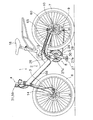
本発明の第1実施形態を採用した自転車は、図1に示すように、前後サスペンション付きのマウンテンバイクである。この自転車は、リアサスペンション13付きのフレーム体2とフロントサスペンション14付きのフロントフォーク3とを有するフレーム1と、ハンドル部4と、フロントフォーク3に装着された前輪6と、ハブダイナモ10が装着された後輪7と、前後の変速装置8,9を含む駆動部5と、前後の変速装置8,9を含む各部を制御するための制御装置30と、複数の電装品50を装着するための電装品ホルダー31(図2参照)とを備えている。
[First Embodiment]
The bicycle employing the first embodiment of the present invention is a mountain bike with front and rear suspensions as shown in FIG. This bicycle has a
フレーム1のフレーム体2は、異形角パイプを溶接して製作されたものである。フレーム体2には、サドル18や駆動部5を含む各部が取り付けられている。フロントフォーク3は、フレーム体2の前部に斜めに傾いた軸回りに揺動自在に装着されている。
The
ハンドル部4は、図2に示すように、フロントフォーク3の上部に固定されたハンドルステム12と、ハンドルステム12に固定されたハンドルバー15とを有している。ハンドルバー15の両端にはブレーキレバー16とグリップ17とが装着されている。ブレーキレバー16の装着部分には、前後の変速装置8,9の手動変速操作を行う変速スイッチ20b,20aが装着されている。また、ハンドルバー15には、ハンドルステム12と変速スイッチ20aとの間に電装品ホルダー31が装着されている。
As shown in FIG. 2, the handle portion 4 includes a
後輪7のハブダイナモ10は、ディスクブレーキのブレーキディスク60及び多段ギアが装着されたフリーホイールを装着可能なハブであり、内部に後輪7の回転により発電する交流発電機(図示せず)を有している。この交流発電機は、接続コード65を介して制御装置30と電装品ホルダー31に接続されている。
The
駆動部5は、フレーム体2の下部(ハンガー部)に設けられクランク27及びフロントディレーラ26を有する前変速装置8と、たとえば9つのスプロケットを有する多段ギア(図示せず)及びリアディレーラ28を有する後変速装置9とを有している。クランク27は、たとえば3つのスプロケットを有するギアクランク27aと左クランク27bとを有している。また、駆動部5は、ギアクランク27aと多段ギアとのそれぞれいずれかのスプロケットに掛け渡されたチェーン29を有している。このような駆動部5においては、変速スイッチ20a,20bを操作すると、変速スイッチ20a,20bの操作信号が制御装置30によって処理される。そして、ギアクランク27aと多段ギアとのそれぞれいずれかのスプロケットに掛け渡されたチェーン29が、ギアクランク27aと多段ギアとのそれぞれ異なるスプロケットに案内される。
The
制御装置30は、たとえば、フレーム体2の下部のハンガー部に装着されており、フロントディレーラ26に隣接して設けられている。この制御装置30は、交流発電機に接続コード65を介して接続されている。制御装置30は、交流発電機で生成された電力によって駆動されており、供給された電力により、フロントディレーラ26と、接続コード(図示しない)を介して接続されたリアディレーラ28とを制御している。
For example, the
電装品ホルダー31は、ハブダイナモ10の交流発電機からの電力や電気信号等の出力を複数の電装品50に供給するためのものである。この電装品ホルダー31は、図2又は図4に示すように、ハウジング32と、入力部33と、出力部34とを有している。ハウジング32には、装着部材35が取り付けられている。この装着部材35によって、ハウジング32はハンドルバー15に着脱自在に装着されている。入力部33はハウジング32に設けられており、入力部33には第1接続コード66が接続されている。この第1接続コード66は、入力部33と交流発電機とを接続している。出力部34は、ハウジング32に設けられており、第1から第4出力部34a,34b,34c,34dを有している。第1および第2出力部34a,34bは矩形状の雌外部端子となっており、第3および第4出力部34c,34dは円形状の雌外部端子となっている。
The
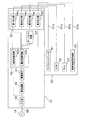
また、電装品ホルダー31の内部には、図3に示すように、整流回路40と蓄電素子41と調整回路42とオートライト回路43とが内蔵されている。整流回路40は、入力部33に入力された交流発電機19からの交流電力を直流電力に変換して整流するためのものである。この整流回路40によって整流された直流電力は、整流回路40から蓄電素子41へと出力される。蓄電素子41は、たとえば大容量コンデンサなどからなっており、整流回路40で整流された直流電力を蓄えるためのものである。ここで、蓄電素子41をコンデンサに代えてニッケル・カドニウム電池やリチウムイオン電池やニッケル水素電池などの二次電池で構成してもよい。この蓄電素子41において蓄えられた直流電力は、蓄電素子41から後述する調整回路42の電圧調整回路42aへと供給される。
In addition, as shown in FIG. 3, a
調整回路42は、電力や電気信号等を後述する複数の電装品50(サイクルコンピュータ51、ラジオ52、ライト53および携帯電話用充電器54)ごとで使用できるように所定の電力や信号等に調整するためのものである。調整回路42は、電圧調整回路42aと波形成形回路42bとからなっている。電圧調整回路42aは、蓄電素子41から供給された直流電力を、所定の電圧に調整して、第1出力部34a、第2出力部34b、オートライト回路43および第4出力部34dそれぞれに出力している。この電圧調整回路42aにおいては、蓄電素子41から供給された直流電力が、たとえば、1.2V、3.0V、3.5Vおよび3.7Vに調整されている。そして、1.2Vの直流電力が第1出力部34aに、3.0Vの直流電力が第2出力部34bに、3.5Vの直流電力がオートライト回路43に、3.7Vの直流電力が第4出力部34dにそれぞれ出力される。波形成形回路42bは、入力部33に入力された交流発電機19からの電気信号(正弦波)をパルス信号(方形波)に変換するためのものである。このパルス信号は、波形成形回路42bから第1出力部34aに出力される。オートライト回路43は、センサー(図示しない)からの信号に基づいて電力を制御してライトの点灯を自動的にオンオフするために設けられている。このオートライト回路43は、電圧調整回路42aからの直流電力を制御して第3出力部34cに出力している。このように調整回路42およびオートライト回路43において調整された電力や電気信号は、第1から第4出力部34a,34b,34c,34dから複数の電装品50に供給される。
The
複数の電装品50は、図4に示すように、たとえば、サイクルコンピュータ51、ラジオ52、ライト53および携帯電話用充電器54からなっている。サイクルコンピュータ51およびラジオ52は、電装品ホルダー31に着脱自在に装着される。サイクルコンピュータ51およびラジオ52それぞれには、雄コネクタ端子51a,52aが一体に形成されている。サイクルコンピュータ51の雄コネクタ端子51aは第1出力部34aに着脱自在に接続され、ラジオ52の雄コネクタ端子52aは第2出力部34bに着脱自在に接続される。サイクルコンピュータ51は各種の走行情報を表示可能な液晶表示部51bを有している。サイクルコンピュータ51には、マイクロコンピュータからなる制御部(図示しない)が内蔵されている。この制御部は、第1出力部34aから出力されたパルス信号に基づいて各種の走行情報(たとえば走行速度や走行距離)を導出して、各種の走行情報を液晶表示部51bに表示する。
As shown in FIG. 4, the plurality of
ラジオ52は、各種放送局(AM、FM等)や各種周波数を表示可能な液晶表示部52bを有している。また、ラジオ52には、各種放送局や各種周波数を選択するための操作ボタン52cおよびボリューム調整つまみ52dが設けられている。ライト53および携帯電話用充電器54は、ハンドルバー15に着脱自在に装着されている。ライト53および携帯電話用充電器54それぞれには、第2接続コード67a,67bの一端が接続されている。ライト53の第2接続コード67aの他端は第3出力部34cに着脱自在に接続され、携帯電話用充電器54の第2接続コード67bの他端は第4出力部34dに着脱自在に接続される。このようにして、ライト53および携帯電話用充電器54は、第2接続コード67a,67bを介して電装品ホルダー31に着脱自在に接続される。ライト53は、オンオフスイッチ53cを有している。このオンオフスイッチ53cによって、ライト53のオンオフを行うことができる。携帯電話用充電器54は、携帯電話を充電するための充電端子(図示しない)を有している。この携帯電話用充電器54は、携帯電話を携帯電話用充電器54に装着したときに、携帯電話用充電器54の充電端子が携帯電話に設けられた充電端子(図示しない)に接触して携帯電話を充電する。
The
このような第1実施形態では、電装品ホルダー31が、整流回路40において、ハブダイナモ10の交流発電機19から入力部33に入力された交流電力を直流電力に変換して整流している。そして、調整回路42の電圧調整回路42aにおいて、蓄電素子41から供給された直流電力を所定の電圧に調整して第1から第4出力部34a,34b,34c,34dそれぞれに出力している。また、電装品ホルダー31は、調整回路42の波形成形回路42bにおいて、ハブダイナモ10の交流発電機19から入力部33に入力された電気信号(正弦波)をパルス信号(方形波)に変換している。このパルス信号は、波形成形回路42bから第1出力部34aに出力されている。このように調整回路42において調整された電力や電気信号は、第1から第4出力部34a,34b,34c,34dから複数の電装品50に供給されている。このような電装品ホルダー31を用いると、調整回路42においてハブダイナモ10からの電力および電気信号を複数の電装品50ごとで使用できるように調整した後、調整回路42で調整されたハブダイナモ10の電力および電気信号を第1から第4出力部34a,34b,34c,34dから複数の電装品50へと供給できる。これにより、ハブダイナモ10からの電力および電気信号を複数の電装品50に安定的に供給することができる。
In the first embodiment as described above, the
〔第2実施形態〕
本発明の第2実施形態を採用した自転車は、図1に示したように、前後サスペンション付きのマウンテンバイクである。この自転車は、リアサスペンション13付きのフレーム体2とフロントサスペンション14付きのフロントフォーク3とを有するフレーム1と、ハンドル部4と、フロントフォーク3に装着された前輪6と、ハブダイナモ10が装着された後輪7と、前後の変速装置8,9を含む駆動部5と、前後の変速装置8,9を含む各部を制御するための制御装置30と、複数の電装品150を装着するための電装品ホルダー131(図6参照)とを備えている。この第2実施形態では、電装品ホルダー131を除いた構成は第1実施形態の構成と同一のため同一部分の構成については説明を省略し、電装品ホルダー131の説明のみを以下に行うものとする。
[Second Embodiment]
A bicycle employing the second embodiment of the present invention is a mountain bike with front and rear suspensions as shown in FIG. This bicycle has a
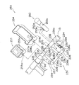
電装品ホルダー131は、ハブダイナモ10の交流発電機からの電力や電気信号等の出力を複数の電装品150に供給するためのものである。この電装品ホルダー131は、図6に示すように、ハウジング132と、入力部133と、出力部134とを有している。ハウジング132には、装着部材135が取り付けられている。この装着部材135によって、ハウジング132はハンドルバー15に着脱自在に装着される。また、ハウジング132には第1装着部132aが形成されており、この第1装着部132aは、複数の電装品150のいずれか1つを着脱自在に装着可能になっている。第1装着部132aは、第1凸部132bを有している。第1凸部132bは、ハウジング132がハンドルバー15に装着された状態において、ハウジング132の上面で前後方向に長く形成されている。この第1凸部132bは、両側壁がハウジング132の上面からハウジング132の外方に向けて末広がりテーパ状に形成されている。入力部133はハウジング132に設けられており、入力部133には第1接続コード66が接続されている。この第1接続コード66は、入力部133と交流発電機とを接続している。
The
出力部134は複数の第1接点端子136を有しており、複数の第1接点端子136はハウジング132に設けられている。これら複数の第1接点端子136は、たとえば8個の第1接点端子136からなっている。これら8個の第1接点端子136は、2個の第1接点端子136が互いに対になった4組の一対の第1接点端子136a,136b,136c,136dからなっている。一対の第1接点端子136a,136b,136c,136dは、第1凸部132bの両側に設けられている。この一対の第1接点端子136a,136b,136c,136dが、第1凸部132bの長手方向に並べて配置されている。
The
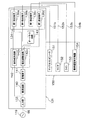
また、電装品ホルダー131の内部には、図5に示すように、整流回路140と蓄電素子141と調整回路142とオートライト回路143とが内蔵されている。整流回路140は、入力部133に入力された交流発電機119からの交流電力を直流電力に変換して整流するためのものである。この整流回路140によって整流された直流電力は、整流回路140から蓄電素子141へと出力される。蓄電素子141は、たとえば大容量コンデンサなどからなっており、整流回路140で整流された直流電力を蓄えるためのものである。ここで、蓄電素子141をコンデンサに代えてニッケル・カドニウム電池やリチウムイオン電池やニッケル水素電池などの二次電池で構成してもよい。この蓄電素子141において蓄えられた直流電力は、蓄電素子141から後述する調整回路142の電圧調整回路142aへと供給される。
In addition, as shown in FIG. 5, a
調整回路142は、電力や電気信号等を後述する複数の電装品150(サイクルコンピュータ151、ラジオ152、ライト153および携帯電話用充電器154)ごとで使用できるように所定の電力や信号等に調整するためのものである。調整回路142は、電圧調整回路142aと波形成形回路142bとからなっている。電圧調整回路142aは、蓄電素子141から供給された直流電力を、所定の電圧に調整して、3組の一対の第1接点端子136a,136b,136dおよびオートライト回路143それぞれに出力している。この電圧調整回路142aにおいては、蓄電素子141から供給された直流電力が、たとえば、1.2V、3.0V、3.5Vおよび3.7Vに調整されている。そして、1.2Vの直流電力が一対の第1接点端子136aに、3.0Vの直流電力が一対の第1接点端子136bに、3.5Vの直流電力がオートライト回路143に、3.7Vの直流電力が一対の第1接点端子136dにそれぞれ出力される。波形成形回路142bは、入力部133に入力された交流発電機119からの電気信号(正弦波)をパルス信号(方形波)に変換するためのものである。このパルス信号は、波形成形回路142bから第1接点端子136aに出力される。オートライト回路43は、センサー(図示しない)からの信号に基づいて電力を制御してライトの点灯を自動的にオンオフするために設けられている。このオートライト回路143は、電圧調整回路142aからの直流電力を制御して一対の第1接点端子136cに出力している。このように調整回路142およびオートライト回路143において調整された電力や電気信号は、4組の一対の第1接点端子136a,136b,136c,136dから複数の電装品150に供給される。
The
複数の電装品150は、図6に示すように、たとえば、サイクルコンピュータ151、ラジオ152、ライト153および携帯電話用充電器154からなっている。サイクルコンピュータ151、ラジオ152、携帯電話用充電器154およびライト153は、いずれか1つが、第1装着部132aにおいてハウジング132に着脱自在に装着可能になっている。サイクルコンピュータ151、ラジオ152、ライト153および携帯電話用充電器154それぞれには、第1凹部151a,152a,153a,154aが設けられている。第1凹部151a,152a,153a,154aは、長溝状に形成されており、ハウジング132に設けられた第1凸部132bに嵌合できるように両側壁が底部から開口部側に向けて先細りテーパ状に形成されている。
As shown in FIG. 6, the plurality of
サイクルコンピュータ151、ラジオ152、ライト153および携帯電話用充電器154それぞれには、一対の第2接点端子151b,152b,153b,154bが設けられている。各電装品151,152,153,154の一対の第2接点端子151b,152b,153b,154bは、サイクルコンピュータ151、ラジオ152、ライト153、携帯電話用充電器154の順に第1凹部151a,152a,153a,154aの長手方向に位置をずらして、第1凹部151a,152a,153a,154aの両側に配置されている。これにより、各電装品151,152,153,154に設けられた一対の第2接点端子151b,152b,153b,154bは、電装品150の第1凹部151a,152a,153a,154aをハウジング132の第1凸部132bに嵌合したときに、出力部134の4組の一対の第1接点端子136a,136b,136c,136dのうち所定の一対の第1接点端子に電気的に接続される(図5参照)。サイクルコンピュータ151は各種の走行情報を表示可能な液晶表示部151cを有している。サイクルコンピュータ151には、マイクロコンピュータからなる制御部(図示しない)が内蔵されている。この制御部は、第1接点端子136aから出力されたパルス信号に基づいて各種の走行情報(たとえば走行速度や走行距離)を導出して、各種の走行情報を液晶表示部151cに表示する。
Each of the
ラジオ152は、各種放送局(AM、FM等)や各種周波数を表示可能な液晶表示部152cを有している。また、ラジオ152には、各種放送局や各種周波数を選択するための操作ボタン152dおよびボリューム調整つまみ152eが設けられている。ライト153は、オンオフスイッチ153cを有している。このオンオフスイッチ153cによって、ライト153のオンオフを行うことができる。携帯電話用充電器154は、携帯電話を充電するための充電端子(図示しない)を有している。この携帯電話用充電器154は、携帯電話を携帯電話用充電器154に装着したときに、携帯電話用充電器154の充電端子が携帯電話に設けられた充電端子(図示しない)に接触して携帯電話を充電する。
The
このような第2実施形態では、電装品ホルダー131が、整流回路140において、ハブダイナモ10の交流発電機119から入力部133に入力された交流電力を直流電力に変換して整流している。そして、調整回路142の電圧調整回路142aにおいて、蓄電素子141から供給された直流電力を所定の電圧に調整して4組の一対の第1接点端子136a,136b,136c,136dそれぞれに出力している。また、電装品ホルダー131は、調整回路142の波形成形回路142bにおいて、ハブダイナモ10の交流発電機119から入力部133に入力された電気信号(正弦波)をパルス信号(方形波)に変換している。このパルス信号は、波形成形回路142bから一対の第1接点端子136aに出力されている。このように調整回路142において調整された電力や電気信号は、4組の一対の第1接点端子136a,136b,136c,136dから複数の電装品150に供給されている。このような電装品ホルダー131を用いると、調整回路142においてハブダイナモ10からの電力および電気信号を複数の電装品150ごとで使用できるように調整した後、調整回路142で調整されたハブダイナモ10の電力および電気信号を4組の一対の第1接点端子136a,136b,136c,136dから複数の電装品150へと供給できる。これにより、ハブダイナモ10からの電力および電気信号を複数の電装品150に安定的に供給することができる。
In the second embodiment, the
〔第3実施形態〕
本発明の第3実施形態を採用した自転車は、図1に示したように、前後サスペンション付きのマウンテンバイクである。この自転車は、リアサスペンション13付きのフレーム体2とフロントサスペンション14付きのフロントフォーク3とを有するフレーム1と、ハンドル部4と、フロントフォーク3に装着された前輪6と、ハブダイナモ10が装着された後輪7と、前後の変速装置8,9を含む駆動部5と、前後の変速装置8,9を含む各部を制御するための制御装置30と、複数の電装品250を装着するための電装品ホルダー231(図8参照)とを備えている。この第3実施形態では、電装品ホルダー231を除いた構成は第1実施形態の構成と同一のため同一部分の構成については説明を省略し、電装品ホルダー231の説明のみを以下に行うものとする。
[Third Embodiment]
A bicycle adopting the third embodiment of the present invention is a mountain bike with front and rear suspensions as shown in FIG. This bicycle has a
電装品ホルダー231は、ハブダイナモ10の交流発電機からの電力や電気信号等の出力を複数の電装品250に供給するためのものである。この電装品ホルダー231は、図8に示すように、ハウジング232と、入力部233と、出力部234とを有している。ハウジング232には、装着部材235が取り付けられている。この装着部材235によって、ハウジング232はハンドルバー15に着脱自在に装着される。ハウジング232には複数の電装品250に応じた複数の第2装着部236が形成されており、これら複数の第2装着部236のうち所定の第2装着部に、複数の電装品250それぞれが着脱自在に装着可能になっている。複数の第2装着部236は、たとえば2つの第3凸部236a,236bと1つの第3凹部236cとを有している。2つの第3凸部236a,236bは、ハウジング232がハンドルバー15に装着された状態において、所定の間隔を隔ててハウジング232の上面2箇所で前後方向に長く形成されている。ハウジング232の上面2箇所に形成された第3凸部236a,236bは、それぞれの両側壁がハウジング232の上面からハウジング232の外方に向けて末広がりテーパ状に形成されている。また、第3凹部236cは、ハウジング232がハンドルバー15に装着された状態において、ハウジング232の側面に形成されている。入力部233はハウジング232に設けられており、入力部233には第1接続コード66が接続されている。この第1接続コード66は、入力部233と交流発電機とを接続している。
The
出力部234は複数の第2外部端子237を有しており、複数の第2外部端子237はハウジング232に設けられている。これら複数の第2外部端子237は、たとえば4個の第2接点端子238と2個の第2コネクタ端子239とからなっている。4個の第2接点端子238は、2個の第2接点端子238が互いに対になった2組の一対の第2接点端子238a,238bからなっている。一対の第2接点端子238a,238bは、ハウジング232の上面2箇所に形成された第3凸部236a,236bそれぞれの両側に設けられている。2個の第2コネクタ端子239は、第2コネクタ端子同士が互いに対になっており、一対の第2コネクタ端子239aになっている。一対の第2コネクタ端子239aは、たとえば雌コネクタ端子になっており、ハウジング232の側面に形成された第3凹部236cの底部から開口部に向けて突出して設けられている。
The
また、電装品ホルダー231の内部には、図7に示すように、整流回路240と蓄電素子241と調整回路242とオートライト回路243とが内蔵されている。整流回路240は、入力部233に入力された交流発電機219からの交流電力を直流電力に変換して整流するためのものである。この整流回路240によって整流された直流電力は、整流回路240から蓄電素子241へと出力される。蓄電素子241は、たとえば大容量コンデンサなどからなっており、整流回路240で整流された直流電力を蓄えるためのものである。ここで、蓄電素子241をコンデンサに代えてニッケル・カドニウム電池やリチウムイオン電池やニッケル水素電池などの二次電池で構成してもよい。この蓄電素子241において蓄えられた直流電力は、蓄電素子241から後述する調整回路242の電圧調整回路242aへと供給される。
In addition, as shown in FIG. 7, a
調整回路242は、電力や電気信号等を後述する複数の電装品250(サイクルコンピュータ251、ライト253および携帯電話用充電器254)ごとで使用できるように所定の電力や信号等に調整するためのものである。調整回路242は、電圧調整回路242aと波形成形回路242bとからなっている。電圧調整回路242aは、蓄電素子241から供給された直流電力を所定の電圧に調整して2組の一対の第2接点端子238a,238bおよびオートライト回路243それぞれに出力している。この電圧調整回路242aにおいては、蓄電素子241から供給された直流電力が、たとえば、1.2V、3.5Vおよび3.7Vに調整されている。そして、1.2Vの直流電力が一対の第2接点端子238aに、3.5Vの直流電力がオートライト回路243に、3.7Vの直流電力が一対の第2接点端子238bにそれぞれ出力される。波形成形回路242bは、入力部233に入力された交流発電機219からの電気信号(正弦波)をパルス信号(方形波)に変換するためのものである。このパルス信号は、波形成形回路242bから第2接点端子238aに出力される。オートライト回路243は、センサー(図示しない)からの信号に基づいて電力を制御してライトの点灯を自動的にオンオフするために設けられている。このオートライト回路243は、電圧調整回路242aからの直流電力を制御して一対の第2コネクタ端子239aに出力している。このように調整回路242およびオートライト回路243において調整された電力や電気信号は、2組の一対の第2接点端子238a,238bおよび一対の第2コネクタ端子239aから複数の電装品250に供給される。
The
複数の電装品250は、図8に示すように、たとえば、サイクルコンピュータ251、ライト253および携帯電話用充電器254からなっている。サイクルコンピュータ251、ライト253および携帯電話用充電器254は、複数の第2装着部236のうち所定の第2装着部において、ハウジング232に着脱自在に装着可能になっている。サイクルコンピュータ251および携帯電話用充電器254それぞれには、第4凹部251a,254aが設けられている。第4凹部251a,254aは、長溝状に形成されており、ハウジング232に設けられた第2装着部236の第3凸部236a,236bに嵌合できるように両側壁が底部から開口部側に向けて先細りテーパ状に形成されている。ライト253には、ハウジング232に設けられた第2装着部236の第3凹部236cに嵌合可能な第4凸部253aが設けられている。
As shown in FIG. 8, the plurality of
サイクルコンピュータ251および携帯電話用充電器254それぞれには、一対の第3接点端子251b,254bが設けられている。一対の第3接点端子251b,254bは、第4凹部251a,254aの両側に配置されている。これにより、サイクルコンピュータ251および携帯電話用充電器254の一対の第3接点端子251b,254bは、第4凹部251a,254aを第2装着部236の第3凸部236a,236bに嵌合したときに、出力部234の一対の第2接点端子238a,238bに電気的に接続される。サイクルコンピュータ251は、各種の走行情報を表示可能な液晶表示部251cを有している。サイクルコンピュータ251には、マイクロコンピュータからなる制御部(図示しない)が内蔵されている。この制御部は、第2接点端子238aから出力されたパルス信号に基づいて各種の走行情報(たとえば走行速度や走行距離)を導出して、各種の走行情報を液晶表示部251cに表示する。携帯電話用充電器254は、携帯電話を充電するための充電端子(図示しない)を有している。この携帯電話用充電器254は、携帯電話を携帯電話用充電器254に装着したときに、携帯電話用充電器254の充電端子が携帯電話に設けられた充電端子(図示しない)に接触して携帯電話を充電する。
Each of the
ライト253には、一対の第3コネクタ端子253bが設けられている。一対の第3コネクタ端子253bそれぞれは、たとえば雄コネクタ端子になっており、第4凸部253aの突出面から外方に突出して配置されている。これにより、ライト253に設けられた一対の第3コネクタ端子253bは、ライト253の第4凸部253aを第2装着部236の第3凹部236cに嵌合したときに、第3凹部236cに設けられた一対の第2コネクタ端子239aに嵌合され電気的に接続される。ライト253は、オンオフスイッチ253cを有している。このオンオフスイッチ253cによって、ライト253のオンオフを行うことができる。
The light 253 is provided with a pair of
このような第3実施形態では、電装品ホルダー231が、整流回路240において、ハブダイナモ10の交流発電機219から入力部233に入力された交流電力を直流電力に変換して整流している。そして、調整回路242の電圧調整回路242aにおいて、蓄電素子241から供給された直流電力を所定の電圧に調整して2組の一対の第2接点端子238a,238bおよび一対の第2コネクタ端子239aそれぞれに出力している。また、電装品ホルダー231は、調整回路242の波形成形回路242bにおいて、ハブダイナモ10の交流発電機219から入力部233に入力された電気信号(正弦波)をパルス信号(方形波)に変換している。このパルス信号は、波形成形回路242bから一対の第2接点端子238aに出力されている。このように調整回路242において調整された電力や電気信号は、2組の一対の第2接点端子238a,238bおよび一対の第2コネクタ端子239aから複数の電装品250に供給されている。このような電装品ホルダー231を用いると、調整回路242においてハブダイナモ10からの電力および電気信号を複数の電装品250ごとで使用できるように調整した後、調整回路242で調整されたハブダイナモ10の電力および電気信号を2組の一対の第2接点端子238a,238bおよび一対の第2コネクタ端子239aから複数の電装品250へと供給できる。これにより、ハブダイナモ10からの電力および電気信号を複数の電装品250に安定的に供給することができる。
In the third embodiment, the
〔他の実施形態〕
(a) 前記第1から第3実施形態では、電装品ホルダー31,131,231が蓄電素子41,141,241を備える場合の例を示したが、必ずしも蓄電素子41,141,241を電装品ホルダー31,131,231に配置する必要はない。たとえば、蓄電素子41,141,241を電装品ホルダー31,131,231に配置しないときは、ハブダイナモ10の交流発電機19,119,219からの電力および電気信号が、蓄電されることなく整流回路40,140,240から電圧調整回路42a,142a,242aに出力される。
[Other Embodiments]
(A) In the first to third embodiments, an example in which the
(b) 前記第1から第3実施形態では、電装品ホルダー31,131,231がハンドルステム12と変速スイッチ20aとの間でハンドルバー15に装着される場合の例を示したが、電装品ホルダー31,131,231をハンドルバー15に装着するときの位置は、前記実施形態に限定されず、どのような位置でも良い。たとえば、図9に示すように、ハンドルバー15がアップハンドルになっている場合、電装品ホルダー331をハンドルバー15の軸方向中央部の上方に配置する。そして、電装品ホルダー331を、電装品ホルダーの両側面に設けられた装着部材335によって、ハンドルステム12から両側上方に延びたハンドルバー15の部分に装着するようにしても良い。
(B) In the first to third embodiments, an example in which the
(c) 前記第3実施形態では、ライト253のみコネクタ端子を用いて接続する場合の例を示したが、図9に示すように、ライト353も、サイクルコンピュータ351および携帯電話用充電器354と同様に、電装品ホルダー331に装着するようにしても良い。このとき、電装品ホルダー331のハウジング332には、ライト353用の第3凸部336cが形成され、この第3凸部336cの両側に一対の第2接点端子338cが設けられる。そして、ライト353に第4凹部353aと第4凹部353aの両側に一対の第3接点端子353bとを設けておくと、ライト353の一対の第3接点端子353bは、第4凹部353aを第3凸部336cに嵌合したときに、一対の第2接点端子338cに電気的に接続することができる。
(C) In the third embodiment, an example in which only the light 253 is connected using a connector terminal is shown. However, as shown in FIG. 9, the light 353 is also connected to the
(d) 前記第1から第3実施形態と前記他の実施形態とでは、電装品ホルダー31,131,231がハンドルバー15に装着される場合の例を示したが、電装品ホルダー31,131,231を自転車に装着する位置は前記実施形態に限定されず、電装品ホルダー31,131,231をフレーム体2に装着しても良い。
(D) In the first to third embodiments and the other embodiments, the example in which the
(e) 前記第1から第3実施形態と前記他の実施形態とでは、後輪7にハブダイナモ10が装着された場合の例を示したが、ハブダイナモ10を装着する位置は前記実施形態に限定されず、前輪6にハブダイナモ10を装着しても良い。
(E) In the first to third embodiments and the other embodiments, an example in which the
(f) 前記第1から第3実施形態と前記他の実施形態とでは、後輪7の回転中心部分に配置されたハブダイナモ10を用いた場合の例を示したが、ダイナモの種類は前記実施形態に限定されず、車輪6,7のタイヤ又はリムに接触させて発電するリムダイナモを用いても良い。
(F) In the first to third embodiments and the other embodiments, an example in which the
(g) 前記第2実施形態では、第1凸部132bに第1凹部151a,152a,153a,154aを嵌合して、ハウジング131に電装品150を装着する場合の例を示した。しかしながら、ハウジング131に電装品150を装着する方法は、前記実施形態に限定されるものではない。たとえば、第1凸部132bを凹部に変更して、第1凹部151a,152a,153a,154aを凸部に変更しても、ハウジング131に電装品150を装着することができる。
(G) In the second embodiment, an example in which the
(h) 前記第3実施形態と前記他の実施形態では、第3凸部236a,236b,336a,336b,336cに第4凹部251a,254a,351a,353a,354aを嵌合して、ハウジング231,331に電装品250,350を装着する場合の例を示した。しかしながら、ハウジング231,331に電装品250,350を装着する方法は、前記実施形態に限定されるものではない。たとえば、第3凸部236a,236bと第3凸部336a,336b,336cとのそれぞれの少なくとも1つを凹部に変更して、電装品250,350の第4凹部251a,254a,351a,353a,354aのうち凹部に対応する電装品の第4凹部251a,254a,351a,353a,354aを凸部に変更しても、ハウジング231,331に電装品250,350を装着することができる。
(H) In the third embodiment and the other embodiments, the
2 フレーム体(フレーム)
10 ハブダイナモ(ダイナモ)
15 ハンドルバー(ハンドル)
19,119,219 交流発電機
31,131,231 電装品ホルダー
32,132,232 ハウジング
33,133,233 入力部
34,134,234 出力部
34a,34b,34c,34d 第1から第4出力部(第1外部端子)
40,140,240 整流回路
41,141,241 蓄電素子
42,142,242 調整回路
42a,142a,242a 電圧調整回路
42b,142b,242b 波形成形回路
43,143,243 オートライト回路
50,150,250,350 電装品
51a,52a 雄コネクタ端子(第1コネクタ端子)
66 第1接続コード
67a,67b 第2接続コード
51,151,251,351 サイクルコンピュータ(表示装置)
52,152 ラジオ
53,153,253,353 ライト(照明器具)
54,154,254,354 携帯電話用充電器
132a 第1装着部
132b 第1凸部
136a,136b,136c,136d 第1接点端子
151a,152a,153a,154a 第1凹部
151b,152b,153b,154b,238a,238b,338c 第2接点端子
236 第2装着部
236a,236b,336a,336b,336c 第3凸部
236c 第3凹部
237 第2外部端子
239,239a 第2コネクタ端子
251a,254a,351a,353a,354a 第4凹部
251b,254b,353b 第3接点端子
253a 第4凸部
253b 第3コネクタ端子
2 Frame body (frame)
10 Hub Dynamo (Dynamo)
15 Handlebar (handle)
19, 119, 219
40, 140, 240
66
52,152 Radio 53,153,253,353 Light (lighting equipment)
54,154,254,354
Claims (16)
前記自転車のフレーム又はハンドルに装着可能なハウジングと、
前記ハウジングに設けられ、前記第1接続コードが接続される入力部と、
前記ハウジングの内部に設けられ、前記入力部から入力される前記ダイナモの前記出力を複数の前記電装品ごとで使用できるように調整する調整回路と、
前記ハウジングに設けられ、前記調整回路で調整された前記ダイナモの前記出力を複数の前記電装品に出力する出力部と、
を備える自転車用電装品ホルダー。 A bicycle electrical component holder mounted on a bicycle having a dynamo and coupled to the dynamo via a first connection cord for supplying output from the dynamo to a plurality of electrical components,
A housing attachable to a frame or handle of the bicycle;
An input portion provided in the housing and connected to the first connection cord;
An adjustment circuit which is provided inside the housing and adjusts the output of the dynamo input from the input unit so that the output can be used for each of the plurality of electrical components;
An output unit that is provided in the housing and outputs the output of the dynamo adjusted by the adjustment circuit to the plurality of electrical components;
Bicycle electrical equipment holder with
複数の前記第1外部端子のうち所定の前記第1外部端子は、前記電装品に接続された第2接続コード又は前記電装品と一体に形成された第1コネクタ端子を介して、前記電装品を着脱自在に接続可能になっている、請求項1に記載の自転車用電装品ホルダー。 The output unit has a plurality of first external terminals,
The predetermined first external terminal among the plurality of first external terminals is connected to the electrical component via the second connection cord or the first connector terminal formed integrally with the electrical component. The bicycle electrical equipment holder according to claim 1, wherein the electrical equipment holder can be detachably connected.
前記第1装着部は、複数の前記電装品のいずれか1つを着脱自在に装着可能になっている、請求項1に記載の自転車用電装品ホルダー。 A first mounting portion is formed in the housing,
2. The bicycle electrical component holder according to claim 1, wherein the first mounting portion is configured to be detachably mountable with any one of the plurality of electrical components.
複数の前記第1接点端子のうち所定の前記第1接点端子は、前記電装品を前記ハウジングの前記第1装着部に装着したときに、前記電装品に設けられた第2接点端子に電気的に接続可能になっている、請求項3に記載の自転車用電装品ホルダー。 The output unit has a plurality of first contact terminals provided in the vicinity of the first mounting unit or the first mounting unit,
Among the plurality of first contact terminals, the predetermined first contact terminal is electrically connected to a second contact terminal provided on the electrical component when the electrical component is mounted on the first mounting portion of the housing. The bicycle electrical component holder according to claim 3, wherein the bicycle electrical component holder can be connected to the bicycle.
前記第1凸部は、前記電装品に設けられた第1凹部に嵌合可能になっている、請求項3又は4に記載の自転車用電装品ホルダー。 The first mounting portion has a first convex portion,
The bicycle electrical component holder according to claim 3 or 4, wherein the first convex portion can be fitted into a first concave portion provided in the electrical component.
前記第2凹部は、前記電装品に設けられた第2凸部に嵌合可能になっている、請求項3又は4に記載の自転車用電装品ホルダー。 The first mounting portion has a second recess,
The bicycle electrical component holder according to claim 3 or 4, wherein the second concave portion can be fitted into a second convex portion provided in the electrical component.
複数の前記第2装着部それぞれは、複数の前記電装品それぞれを着脱自在に装着可能になっている、請求項1に記載の自転車用電装品ホルダー。 The housing is formed with a plurality of second mounting portions corresponding to the plurality of electrical components,
2. The bicycle electrical component holder according to claim 1, wherein each of the plurality of second mounting portions is configured to be detachably mountable with the plurality of electrical components.
前記第2外部端子は、前記電装品に設けられた第3外部端子に接続可能になっている、請求項7に記載の自転車用電装品ホルダー。 The output unit has a plurality of second external terminals, and the second external terminals are provided in either the second mounting unit or the vicinity of the second mounting unit for each second mounting unit. ,
The bicycle electrical component holder according to claim 7, wherein the second external terminal is connectable to a third external terminal provided on the electrical component.
前記第2接点端子と前記第3接点端子とは、前記電装品を前記ハウジングの前記第2装着部に装着したときに電気的に接続される、請求項8に記載の自転車用電装品ホルダー。 When the second external terminal is provided in the vicinity of the second mounting portion, the second and third external terminals are second and third contact terminals,
The bicycle electrical component holder according to claim 8, wherein the second contact terminal and the third contact terminal are electrically connected when the electrical component is mounted on the second mounting portion of the housing.
前記第2コネクタ端子と前記第3コネクタ端子とは、前記電装品を前記ハウジングの前記第2装着部に装着したときに電気的に接続される、請求項8に記載の自転車用電装品電装品ホルダー。 When the second external terminal is provided in the second mounting portion, the second and third external terminals are second and third connector terminals,
The bicycle electrical component electrical component according to claim 8, wherein the second connector terminal and the third connector terminal are electrically connected when the electrical component is mounted on the second mounting portion of the housing. holder.
前記第3凸部又は前記第3凹部は前記電装品に設けられた第4凹部又は第4凸部に嵌合可能になっている、請求項7から11のいずれかに記載の自転車用電装品ホルダー。 The second mounting part has a third convex part or a third concave part,
The bicycle electrical component according to any one of claims 7 to 11, wherein the third convex portion or the third concave portion can be fitted into a fourth concave portion or a fourth convex portion provided in the electrical component. holder.
前記ダイナモの前記出力は、電力および電気信号を有しており、
前記調整回路は、前記入力部から入力された前記ダイナモの前記電気信号を表示信号に変換して、前記表示装置が接続される前記出力部に前記表示信号を送出している、請求項1から12のいずれかに記載の自転車用電装品ホルダー。 The plurality of electrical components includes a display device capable of displaying a running state of the bicycle,
The output of the dynamo has power and electrical signals;
The adjustment circuit converts the electrical signal of the dynamo input from the input unit into a display signal, and sends the display signal to the output unit to which the display device is connected. The bicycle electrical accessory holder according to any one of 12 above.
前記ダイナモの前記出力は、電力および電気信号を有しており、
前記調整回路は、前記入力部から入力された前記ダイナモの前記電力を、前記ラジオ、前記携帯電話用充電器および前記照明器具が接続される前記出力部に調整して送出している、請求項1から14のいずれかに記載の自転車用電装品ホルダー。 The plurality of electrical components include a radio, a mobile phone charger and a lighting fixture,
The output of the dynamo has power and electrical signals;
The adjustment circuit adjusts and sends the power of the dynamo input from the input unit to the output unit to which the radio, the mobile phone charger and the lighting fixture are connected. The bicycle electrical equipment holder according to any one of 1 to 14.
前記ハウジングの内部に配置され、前記入力部から入力される前記ダイナモの前記電力を蓄電する蓄電素子をさらに備える、請求項1から15のいずれかに記載の自転車用電装品ホルダー。 The output of the dynamo has power and electrical signals;
The bicycle electrical component holder according to any one of claims 1 to 15, further comprising a power storage element that is disposed inside the housing and stores the power of the dynamo input from the input unit.
Priority Applications (7)
| Application Number | Priority Date | Filing Date | Title |
|---|---|---|---|
| JP2003339134A JP2005104258A (en) | 2003-09-30 | 2003-09-30 | Electrical instrument holder for bicycle |
| TW093103222A TWI232828B (en) | 2003-09-30 | 2004-02-11 | Electric component holder for bicycle |
| AT04022573T ATE425908T1 (en) | 2003-09-30 | 2004-09-22 | HOLDER FOR ELECTRICAL COMPONENTS ON BICYCLES |
| EP04022573A EP1520773B1 (en) | 2003-09-30 | 2004-09-22 | Electrical component holder for bicycle |
| DE602004020038T DE602004020038D1 (en) | 2003-09-30 | 2004-09-22 | Holder for electrical components on bicycles |
| US10/711,560 US7411307B2 (en) | 2003-09-30 | 2004-09-24 | Apparatus for providing electrical signals to bicycle components |
| CNB2004100852116A CN100377956C (en) | 2003-09-30 | 2004-09-30 | Apparatus for providing electrical signals to bicycle components |
Applications Claiming Priority (1)
| Application Number | Priority Date | Filing Date | Title |
|---|---|---|---|
| JP2003339134A JP2005104258A (en) | 2003-09-30 | 2003-09-30 | Electrical instrument holder for bicycle |
Publications (1)
| Publication Number | Publication Date |
|---|---|
| JP2005104258A true JP2005104258A (en) | 2005-04-21 |
Family
ID=34309006
Family Applications (1)
| Application Number | Title | Priority Date | Filing Date |
|---|---|---|---|
| JP2003339134A Pending JP2005104258A (en) | 2003-09-30 | 2003-09-30 | Electrical instrument holder for bicycle |
Country Status (7)
| Country | Link |
|---|---|
| US (1) | US7411307B2 (en) |
| EP (1) | EP1520773B1 (en) |
| JP (1) | JP2005104258A (en) |
| CN (1) | CN100377956C (en) |
| AT (1) | ATE425908T1 (en) |
| DE (1) | DE602004020038D1 (en) |
| TW (1) | TWI232828B (en) |
Cited By (9)
| Publication number | Priority date | Publication date | Assignee | Title |
|---|---|---|---|---|
| KR101160417B1 (en) * | 2010-09-30 | 2012-06-26 | (주)쉬운기술 | A Bicycle Generating System |
| WO2013129421A1 (en) | 2012-03-02 | 2013-09-06 | 本田技研工業株式会社 | Saddle-type vehicle |
| CN103287530A (en) * | 2012-03-02 | 2013-09-11 | 本田技研工业株式会社 | Configuration structure of voltage converter in straddle-type vehicle |
| JP2013180710A (en) * | 2012-03-02 | 2013-09-12 | Honda Motor Co Ltd | Charging structure of portable information terminal |
| DE102013204130A1 (en) | 2012-05-16 | 2013-11-21 | Honda Motor Co., Ltd. | Wireless charging structure for a mobile information terminal in a vehicle |
| JP2017165214A (en) * | 2016-03-15 | 2017-09-21 | 本田技研工業株式会社 | Lid holding structure |
| JP2018058497A (en) * | 2016-10-05 | 2018-04-12 | 株式会社シマノ | Power supply device for bicycle and electric device for bicycle having the same |
| JP2021523856A (en) * | 2018-05-24 | 2021-09-09 | テヨン キム | Bicycle integrated multi-function lighting device |
| US11975650B2 (en) | 2022-03-29 | 2024-05-07 | Honda Motor Co., Ltd. | Detachable fog light unit |
Families Citing this family (37)
| Publication number | Priority date | Publication date | Assignee | Title |
|---|---|---|---|---|
| US8298036B2 (en) | 2006-08-04 | 2012-10-30 | Zen Design Group, Ltd. | Dynamo powered amusement device |
| JP2005104258A (en) * | 2003-09-30 | 2005-04-21 | Shimano Inc | Electrical instrument holder for bicycle |
| DE102007040738B4 (en) * | 2007-08-28 | 2015-06-25 | Trelock Gmbh | Display and operating system for a bicycle |
| WO2011000398A1 (en) * | 2009-06-30 | 2011-01-06 | Mühlberger GmbH | Arrangement for connecting attachment parts to a vehicle |
| DE102009033564A1 (en) * | 2009-07-16 | 2011-01-20 | Busch & Müller KG | Device for bicycle for providing output voltage, has voltage input for feeding input voltage and voltage output for emitting output voltage, where medium is formed for matching voltage |
| JP5143867B2 (en) * | 2010-06-11 | 2013-02-13 | 株式会社シマノ | Bicycle electrical component control system |
| EP2415658B1 (en) * | 2010-08-03 | 2013-11-27 | Marwi Taiwan Industrial Co., Ltd. | Multifunction power supplying device for a bicycle |
| US8721495B2 (en) * | 2011-06-17 | 2014-05-13 | Shimano Inc. | Rear derailleur and gear shift system |
| CN202179824U (en) * | 2011-07-22 | 2012-04-04 | 北京美亚视景创恒科技有限公司 | Digital body-building equipment cluster system |
| JP5159928B2 (en) * | 2011-07-29 | 2013-03-13 | 株式会社シマノ | Bicycle communication adapter |
| US8449157B2 (en) | 2011-08-16 | 2013-05-28 | Trek Bicycle Corp. | Lighted bicycle wheel hub assembly |
| CN103028259B (en) * | 2011-10-05 | 2016-05-18 | 株式会社吾妻 | Riding toy |
| US9527542B2 (en) | 2012-03-08 | 2016-12-27 | Honda Motor Co., Ltd. | Personal digital assistant attachment structure for saddle-ride vehicle |
| US9018940B2 (en) * | 2012-06-28 | 2015-04-28 | Shimano Inc. | Bicycle rotation detecting device |
| US9394030B2 (en) | 2012-09-27 | 2016-07-19 | Sram, Llc | Rear derailleur |
| US9676444B2 (en) | 2013-10-23 | 2017-06-13 | Sram, Llc | Electromechanical rear derailleur |
| KR101347658B1 (en) * | 2013-11-14 | 2014-01-06 | 이상래 | A direction indicate lamp for bicycle with multi function |
| EP2878524A1 (en) * | 2013-11-27 | 2015-06-03 | Mando Corporation | Human machine interface of electric bicycle |
| US20150177768A1 (en) * | 2013-12-23 | 2015-06-25 | Taigulf Co., Ltd. | Portable green power device |
| US10310535B2 (en) | 2013-12-23 | 2019-06-04 | Taigulf Co., Ltd. | Portable green power device |
| KR20170010292A (en) * | 2014-05-26 | 2017-01-26 | 웬-성 리 | Intelligent energy saving control device for bicycle |
| WO2016083568A1 (en) * | 2014-11-27 | 2016-06-02 | Cobi Gmbh | Holding system for fastening a mobile communication device to a bicycle, and a caddy and a holding frame for such a holding system |
| DE102014117466B4 (en) * | 2014-11-27 | 2021-07-29 | Robert Bosch Gmbh | Holding system for attaching a mobile communication device to a bicycle as well as a removable frame and a holding frame for such a holding system |
| WO2016128586A1 (en) * | 2015-02-12 | 2016-08-18 | Universidad De Salamanca | Control set on a handelbar steered vehicle |
| DE202015005452U1 (en) * | 2015-08-06 | 2016-11-08 | Canyon Bicycles Gmbh | Watch-holder |
| WO2017032893A1 (en) * | 2015-08-26 | 2017-03-02 | Bloks. Ag | Fixing device for fixing an electronic component to a vehicle, in particular a bicycle or a lightweight electric vehicle |
| DE202016008499U1 (en) * | 2015-08-26 | 2018-03-06 | Bloks Ag | Device for controlling electronic components of a vehicle, in particular a bicycle or light vehicle, and for displaying information |
| US20170158274A1 (en) * | 2015-12-07 | 2017-06-08 | Ruben R. Johnson | Detachable mobile mounting device system |
| CN105501347A (en) * | 2015-12-13 | 2016-04-20 | 天津踏浪科技股份有限公司 | Electric bicycle provided with mobile phone charger |
| IT201600080022A1 (en) * | 2016-07-29 | 2018-01-29 | Zehus S P A | Bicycle dynamo |
| US10189535B1 (en) | 2016-10-12 | 2019-01-29 | Arnott T&P Holding, Llc | Motorcycle display unit system and method |
| US20180109125A1 (en) * | 2016-10-14 | 2018-04-19 | Aaron Everest | Smart Phone Charging System |
| WO2018130999A1 (en) * | 2017-01-16 | 2018-07-19 | eurorad Deutschland GmbH | Bicycle frame, in particular for electric bicycles, electric bicycle and mobile lighting device and adapter parts for bicycle accessories |
| CN108199464A (en) * | 2018-01-11 | 2018-06-22 | 北京涌阔科技有限公司 | A kind of bicycle and its power supply-charging method with self-powered charger baby |
| DE102019126866A1 (en) * | 2019-10-07 | 2021-04-08 | Jochen Klieber | Bicycle attachment system and bicycle assembly |
| DE102020200020A1 (en) * | 2020-01-03 | 2021-07-08 | Biketec Gmbh | Display unit, display unit set and electric bike |
| US11303143B2 (en) | 2020-02-12 | 2022-04-12 | Annex Products Pty Ltd | Wireless charging mount for handheld electronic devices |
Family Cites Families (55)
| Publication number | Priority date | Publication date | Assignee | Title |
|---|---|---|---|---|
| US4069451A (en) * | 1976-04-05 | 1978-01-17 | Rouse Paul S | Bicycle generator circuit |
| GB2126438B (en) * | 1982-02-10 | 1986-09-17 | Vincent Joseph Skinner | Lighting system for cycles |
| US4823036A (en) | 1984-12-18 | 1989-04-18 | Roberts Robert E | Disc commutator and brush apparatus for bicycle |
| US4942936A (en) * | 1988-02-12 | 1990-07-24 | Gardner Elmer W Jr | Electrohydraulic/air bike |
| US5015918A (en) * | 1988-07-22 | 1991-05-14 | John Copeland | Bicycle single-wire lighting system with steady-flashing-reflector rear warning device |
| US4961719A (en) * | 1989-07-19 | 1990-10-09 | Gruber, Kaplan & Associates | Variable drive transmission |
| JPH0394197U (en) | 1990-01-17 | 1991-09-25 | ||
| US5059158A (en) * | 1990-05-08 | 1991-10-22 | E.B.T., Inc. | Electronic transmission control system for a bicycle |
| DE59100747D1 (en) * | 1990-06-07 | 1994-02-03 | Ver Drahtwerke Ag Biel | Bicycle light system with dynamo. |
| US5237263A (en) * | 1991-06-17 | 1993-08-17 | Gannon Henry M | Electric and pedal driven bicycle with solar charging |
| JP2569372Y2 (en) | 1992-03-13 | 1998-04-22 | 株式会社キャットアイ | Battery case mounting device |
| DE4212319A1 (en) | 1992-04-13 | 1993-10-14 | Fichtel & Sachs Ag | control device |
| CN2126195U (en) | 1992-05-08 | 1992-12-30 | 新疆前进机器厂 | Charged bicycle headlight or rearlight |
| US5368122A (en) * | 1993-12-21 | 1994-11-29 | Chou; Wen-Cheng | Electrical bicycle |
| US5433284A (en) * | 1993-12-21 | 1995-07-18 | Chou; Wen-Cheng | Electrical bicycle |
| US5551315A (en) * | 1994-02-03 | 1996-09-03 | Pikoulas; George W. | Automatic gear changing system |
| US5713933A (en) * | 1994-11-30 | 1998-02-03 | Medtronic, Inc. | Method and apparatus for automatic pacing threshold determination |
| JPH08207854A (en) | 1994-12-07 | 1996-08-13 | Honda Motor Co Ltd | Battery case mounting structure of motor vehicle |
| IT1276417B1 (en) * | 1995-06-07 | 1997-10-31 | Campagnolo Srl | "SPEED CHANGE DEVICE FOR BICYCLES WITH ELECTRONIC CONTROL" |
| US5599244A (en) * | 1995-08-14 | 1997-02-04 | Ethington; Russell A. | Automatic transmission shifter for velocipedes |
| JP3242820B2 (en) * | 1995-09-28 | 2001-12-25 | 矢崎総業株式会社 | Movable connector positioning mechanism |
| US6002982A (en) * | 1996-11-01 | 1999-12-14 | Fry; William R. | Sports computer with GPS receiver and performance tracking capabilities |
| JP3321045B2 (en) * | 1996-12-20 | 2002-09-03 | 株式会社シマノ | Bicycle electrical operating device |
| JP3490239B2 (en) * | 1997-01-31 | 2004-01-26 | 株式会社シマノ | Mounting device for bicycle display device |
| US6047230A (en) * | 1997-02-27 | 2000-04-04 | Spencer; Marc D. | Automatic bicycle transmission |
| US6192300B1 (en) * | 1997-06-27 | 2001-02-20 | Echowell Electronic Ltd. | Bicycle computer |
| JP3231006B2 (en) * | 1997-08-28 | 2001-11-19 | 株式会社シマノ | Gear change control device for bicycle |
| US6012353A (en) | 1998-02-13 | 2000-01-11 | Shimano, Inc. | Gear position sensing unit |
| US6100615A (en) * | 1998-05-11 | 2000-08-08 | Birkestrand; Orville J. | Modular motorized electric wheel hub assembly for bicycles and the like |
| US6418360B1 (en) * | 1999-01-08 | 2002-07-09 | Shockware | Sensor structure for measuring vehicle suspension related information |
| DE29915125U1 (en) * | 1999-08-28 | 2000-08-17 | Schulz Dieter | Bicycle light system |
| US6094122A (en) * | 1999-09-08 | 2000-07-25 | Ford Motor Company | Mechanical locking connection for electric terminals |
| JP2001122175A (en) * | 1999-10-29 | 2001-05-08 | Sanyo Electric Co Ltd | Motor-assisted bicycle |
| GB2355868A (en) * | 1999-10-30 | 2001-05-02 | Kieron Loy | Bicycle dynamo mobile phone battery charger |
| US7264256B2 (en) * | 2000-02-09 | 2007-09-04 | Shimano, Inc. | Bracket assembly for a motor controlled bicycle transmission |
| JP3396655B2 (en) * | 2000-02-29 | 2003-04-14 | 株式会社シマノ | Bicycle power supply |
| IT1320286B1 (en) * | 2000-03-29 | 2003-11-26 | Campagnolo Srl | MULTIPROCESSOR CONTROL SYSTEM FOR CYCLES, FOR EXAMPLE COMPETITION BICYCLES. |
| US6446745B1 (en) * | 2000-06-30 | 2002-09-10 | Michael John Lee | Control system for electric powered vehicle |
| US6648686B2 (en) | 2000-11-30 | 2003-11-18 | Shimano Inc. | Electrical connector |
| JP2002187584A (en) * | 2000-12-22 | 2002-07-02 | Shimano Inc | Drive control circuit for electric unit for bicycle |
| JP3907166B2 (en) | 2001-08-09 | 2007-04-18 | 本田技研工業株式会社 | Electric small vehicle charging system |
| US6741045B2 (en) * | 2002-04-23 | 2004-05-25 | Shimano, Inc. | Bicycle control apparatus that communicates power and data over a single transmission path |
| US7015598B2 (en) * | 2002-04-23 | 2006-03-21 | Shimano, Inc. | Power control apparatus for a bicycle |
| US6724299B2 (en) * | 2002-06-27 | 2004-04-20 | Shimano, Inc. | Bicycle data communication method and apparatus |
| JP3855870B2 (en) * | 2002-07-16 | 2006-12-13 | 松下電器産業株式会社 | Portable power system |
| JP3645876B2 (en) | 2002-08-30 | 2005-05-11 | 株式会社シマノ | Bicycle electrical equipment control device |
| JP3094197U (en) * | 2002-11-21 | 2003-06-06 | 達碩 張 | Bicycle power supply and charging device |
| TWM242396U (en) * | 2003-09-26 | 2004-09-01 | Everwell Electronic S Co Ltd | Dashboard |
| JP2005104258A (en) * | 2003-09-30 | 2005-04-21 | Shimano Inc | Electrical instrument holder for bicycle |
| JP3845092B2 (en) * | 2004-01-16 | 2006-11-15 | 株式会社シマノ | Bicycle lighting device |
| US7059989B2 (en) * | 2004-06-30 | 2006-06-13 | Shimano Inc. | Bottom bracket structure with dynamo |
| US7145256B2 (en) * | 2004-10-05 | 2006-12-05 | Alan William Koharcheck | Lighting system for a bicycle |
| JP4464853B2 (en) * | 2005-03-16 | 2010-05-19 | アルパイン株式会社 | Detachable connector |
| JP4141453B2 (en) * | 2005-03-16 | 2008-08-27 | 株式会社シマノ | Bicycle power supply |
| JP2007073449A (en) * | 2005-09-09 | 2007-03-22 | Denso Corp | Connector case |
-
2003
- 2003-09-30 JP JP2003339134A patent/JP2005104258A/en active Pending
-
2004
- 2004-02-11 TW TW093103222A patent/TWI232828B/en not_active IP Right Cessation
- 2004-09-22 EP EP04022573A patent/EP1520773B1/en not_active Not-in-force
- 2004-09-22 DE DE602004020038T patent/DE602004020038D1/en active Active
- 2004-09-22 AT AT04022573T patent/ATE425908T1/en not_active IP Right Cessation
- 2004-09-24 US US10/711,560 patent/US7411307B2/en not_active Expired - Fee Related
- 2004-09-30 CN CNB2004100852116A patent/CN100377956C/en not_active Expired - Fee Related
Cited By (15)
| Publication number | Priority date | Publication date | Assignee | Title |
|---|---|---|---|---|
| KR101160417B1 (en) * | 2010-09-30 | 2012-06-26 | (주)쉬운기술 | A Bicycle Generating System |
| EP2740652A1 (en) | 2012-03-02 | 2014-06-11 | Honda Motor Co., Ltd. | Saddle-ride vehicle |
| CN103287530B (en) * | 2012-03-02 | 2016-02-17 | 本田技研工业株式会社 | The arrangement of the voltage changer of the portable information terminal in Straddle-type vehicle |
| JP2013180710A (en) * | 2012-03-02 | 2013-09-12 | Honda Motor Co Ltd | Charging structure of portable information terminal |
| US9346413B2 (en) | 2012-03-02 | 2016-05-24 | Honda Motor Co., Ltd. | Saddle-ride vehicle |
| CN103287530A (en) * | 2012-03-02 | 2013-09-11 | 本田技研工业株式会社 | Configuration structure of voltage converter in straddle-type vehicle |
| WO2013129421A1 (en) | 2012-03-02 | 2013-09-06 | 本田技研工業株式会社 | Saddle-type vehicle |
| EP2759460A1 (en) | 2012-03-02 | 2014-07-30 | Honda Motor Co., Ltd. | Personal digital assistance case of saddle-ride vehicle |
| JP2013237394A (en) * | 2012-05-16 | 2013-11-28 | Honda Motor Co Ltd | Non-contact charging structure for mobile information terminal in vehicle |
| DE102013204130A1 (en) | 2012-05-16 | 2013-11-21 | Honda Motor Co., Ltd. | Wireless charging structure for a mobile information terminal in a vehicle |
| US9368999B2 (en) | 2012-05-16 | 2016-06-14 | Honda Motor Co., Ltd. | Wireless charging structure for mobile information terminal in vehicle |
| JP2017165214A (en) * | 2016-03-15 | 2017-09-21 | 本田技研工業株式会社 | Lid holding structure |
| JP2018058497A (en) * | 2016-10-05 | 2018-04-12 | 株式会社シマノ | Power supply device for bicycle and electric device for bicycle having the same |
| JP2021523856A (en) * | 2018-05-24 | 2021-09-09 | テヨン キム | Bicycle integrated multi-function lighting device |
| US11975650B2 (en) | 2022-03-29 | 2024-05-07 | Honda Motor Co., Ltd. | Detachable fog light unit |
Also Published As
| Publication number | Publication date |
|---|---|
| TWI232828B (en) | 2005-05-21 |
| CN100377956C (en) | 2008-04-02 |
| EP1520773B1 (en) | 2009-03-18 |
| ATE425908T1 (en) | 2009-04-15 |
| TW200512124A (en) | 2005-04-01 |
| EP1520773A1 (en) | 2005-04-06 |
| CN1603200A (en) | 2005-04-06 |
| DE602004020038D1 (en) | 2009-04-30 |
| US20050067203A1 (en) | 2005-03-31 |
| US7411307B2 (en) | 2008-08-12 |
Similar Documents
| Publication | Publication Date | Title |
|---|---|---|
| JP2005104258A (en) | Electrical instrument holder for bicycle | |
| JP4476249B2 (en) | Bicycle lighting device | |
| TWI231279B (en) | Control apparatus for bicycle electrical components | |
| US7147238B2 (en) | Bicycle part with a partitioned chamber | |
| TW553865B (en) | Power source device for bicycle | |
| CN100457543C (en) | Variable speed controller for bicycle | |
| JP2005324648A (en) | Driving unit for bicycle and chain stay for bicycle | |
| TWI244449B (en) | Bicycle power supply | |
| JP6772072B2 (en) | bicycle | |
| TW201711912A (en) | Bicycle electrical control device and system | |
| JP2006244743A (en) | Wiring connection structure for bicycle | |
| JP6991564B2 (en) | Electric bicycle battery device and electric folding bicycle | |
| JP3108520U (en) | Charger | |
| JP2013207823A (en) | Power supply | |
| JP3163417U (en) | Bicycle power generator | |
| US11591042B2 (en) | Power supply device for human-powered vehicle | |
| CN202918020U (en) | Battery for electric bicycle | |
| JP3212859U (en) | Vehicle mounted tools | |
| CN210093279U (en) | Multifunctional mobile phone support | |
| CN210201536U (en) | Multifunctional mobile power supply | |
| JP2018040449A (en) | Component for outdoor equipment | |
| KR20110026126A (en) | Belt pulley mounted on rear wheel of bicycle | |
| CN114435524A (en) | Handle sleeve | |
| CN203984695U (en) | Electric heater | |
| KR20170038201A (en) | Recharger-turn blinker |
Legal Events
| Date | Code | Title | Description |
|---|---|---|---|
| A131 | Notification of reasons for refusal |
Free format text: JAPANESE INTERMEDIATE CODE: A131 Effective date: 20051004 |
|
| A521 | Request for written amendment filed |
Free format text: JAPANESE INTERMEDIATE CODE: A523 Effective date: 20051124 |
|
| A131 | Notification of reasons for refusal |
Free format text: JAPANESE INTERMEDIATE CODE: A131 Effective date: 20060425 |
|
| A02 | Decision of refusal |
Free format text: JAPANESE INTERMEDIATE CODE: A02 Effective date: 20060815 |