JP2005100259A - Array type disk device, program, and method for preventing double fault of drive - Google Patents
Array type disk device, program, and method for preventing double fault of drive Download PDFInfo
- Publication number
- JP2005100259A JP2005100259A JP2003335465A JP2003335465A JP2005100259A JP 2005100259 A JP2005100259 A JP 2005100259A JP 2003335465 A JP2003335465 A JP 2003335465A JP 2003335465 A JP2003335465 A JP 2003335465A JP 2005100259 A JP2005100259 A JP 2005100259A
- Authority
- JP
- Japan
- Prior art keywords
- disk device
- disk
- data
- error
- array type
- Prior art date
- Legal status (The legal status is an assumption and is not a legal conclusion. Google has not performed a legal analysis and makes no representation as to the accuracy of the status listed.)
- Pending
Links
Images


Classifications
-
- G—PHYSICS
- G06—COMPUTING; CALCULATING OR COUNTING
- G06F—ELECTRIC DIGITAL DATA PROCESSING
- G06F11/00—Error detection; Error correction; Monitoring
- G06F11/008—Reliability or availability analysis
-
- G—PHYSICS
- G06—COMPUTING; CALCULATING OR COUNTING
- G06F—ELECTRIC DIGITAL DATA PROCESSING
- G06F11/00—Error detection; Error correction; Monitoring
- G06F11/07—Responding to the occurrence of a fault, e.g. fault tolerance
- G06F11/16—Error detection or correction of the data by redundancy in hardware
- G06F11/20—Error detection or correction of the data by redundancy in hardware using active fault-masking, e.g. by switching out faulty elements or by switching in spare elements
- G06F11/2053—Error detection or correction of the data by redundancy in hardware using active fault-masking, e.g. by switching out faulty elements or by switching in spare elements where persistent mass storage functionality or persistent mass storage control functionality is redundant
- G06F11/2056—Error detection or correction of the data by redundancy in hardware using active fault-masking, e.g. by switching out faulty elements or by switching in spare elements where persistent mass storage functionality or persistent mass storage control functionality is redundant by mirroring
- G06F11/2069—Management of state, configuration or failover
-
- G—PHYSICS
- G06—COMPUTING; CALCULATING OR COUNTING
- G06F—ELECTRIC DIGITAL DATA PROCESSING
- G06F11/00—Error detection; Error correction; Monitoring
- G06F11/07—Responding to the occurrence of a fault, e.g. fault tolerance
- G06F11/16—Error detection or correction of the data by redundancy in hardware
- G06F11/20—Error detection or correction of the data by redundancy in hardware using active fault-masking, e.g. by switching out faulty elements or by switching in spare elements
- G06F11/2053—Error detection or correction of the data by redundancy in hardware using active fault-masking, e.g. by switching out faulty elements or by switching in spare elements where persistent mass storage functionality or persistent mass storage control functionality is redundant
- G06F11/2094—Redundant storage or storage space
-
- G—PHYSICS
- G06—COMPUTING; CALCULATING OR COUNTING
- G06F—ELECTRIC DIGITAL DATA PROCESSING
- G06F11/00—Error detection; Error correction; Monitoring
- G06F11/07—Responding to the occurrence of a fault, e.g. fault tolerance
- G06F11/16—Error detection or correction of the data by redundancy in hardware
- G06F11/1658—Data re-synchronization of a redundant component, or initial sync of replacement, additional or spare unit
- G06F11/1662—Data re-synchronization of a redundant component, or initial sync of replacement, additional or spare unit the resynchronized component or unit being a persistent storage device
-
- G—PHYSICS
- G06—COMPUTING; CALCULATING OR COUNTING
- G06F—ELECTRIC DIGITAL DATA PROCESSING
- G06F11/00—Error detection; Error correction; Monitoring
- G06F11/07—Responding to the occurrence of a fault, e.g. fault tolerance
- G06F11/16—Error detection or correction of the data by redundancy in hardware
- G06F11/20—Error detection or correction of the data by redundancy in hardware using active fault-masking, e.g. by switching out faulty elements or by switching in spare elements
- G06F11/2053—Error detection or correction of the data by redundancy in hardware using active fault-masking, e.g. by switching out faulty elements or by switching in spare elements where persistent mass storage functionality or persistent mass storage control functionality is redundant
- G06F11/2089—Redundant storage control functionality
-
- G—PHYSICS
- G06—COMPUTING; CALCULATING OR COUNTING
- G06F—ELECTRIC DIGITAL DATA PROCESSING
- G06F11/00—Error detection; Error correction; Monitoring
- G06F11/07—Responding to the occurrence of a fault, e.g. fault tolerance
- G06F11/16—Error detection or correction of the data by redundancy in hardware
- G06F11/20—Error detection or correction of the data by redundancy in hardware using active fault-masking, e.g. by switching out faulty elements or by switching in spare elements
- G06F11/2097—Error detection or correction of the data by redundancy in hardware using active fault-masking, e.g. by switching out faulty elements or by switching in spare elements maintaining the standby controller/processing unit updated
-
- G—PHYSICS
- G06—COMPUTING; CALCULATING OR COUNTING
- G06F—ELECTRIC DIGITAL DATA PROCESSING
- G06F2201/00—Indexing scheme relating to error detection, to error correction, and to monitoring
- G06F2201/81—Threshold
Abstract
Description
本発明は主として、コンピュータの外部記憶装置であるディスク装置に関わり、特に、ディスクアレイを構成するアレイ型ディスク装置において複数台のディスク装置が同時に故障を起こすことを予防するための技術に関わり、さらに、冗長度を有するディスクアレイグループを構成するディスク装置間のデータ移行時における、ホストI/Oレスポンス向上及び確実性向上技術に関する。 The present invention mainly relates to a disk device that is an external storage device of a computer, and more particularly to a technique for preventing a plurality of disk devices from simultaneously failing in an array type disk device constituting a disk array. The present invention relates to a technique for improving host I / O response and improving reliability at the time of data migration between disk devices constituting a disk array group having redundancy.
計算機に接続される記憶装置システムの一種に、アレイ型ディスク装置がある。アレイ型ディスク装置は、RAID(Redundant Arrays of Inexpensive Disks)とも呼ばれ、アレイ状に配置された複数のディスク装置及びそれらを制御する制御部とを有する記憶装置である。アレイ型ディスク装置では、リード要求(データの読み出し要求)およびライト要求(データの書き込み要求)がディスク装置の並列動作によって高速に処理され、かつデータに冗長性が付加される。アレイ型ディスク装置は、非特許文献1に開示されているように、付加される冗長データの種類とその構成により5つのレベルに分類されている。
One type of storage device system connected to a computer is an array type disk device. An array type disk device is also called RAID (Redundant Arrays of Inexpensive Disks), and is a storage device having a plurality of disk devices arranged in an array and a control unit for controlling them. In an array type disk device, read requests (data read requests) and write requests (data write requests) are processed at high speed by the parallel operation of the disk devices, and redundancy is added to the data. As disclosed in Non-Patent
市場に出回っているアレイ型ディスク装置においては、運用されているディスク装置が故障する場合を想定し、スペアディスク装置をあらかじめ同一アレイ型ディスク装置内に搭載しておくことが一般的である。アレイ型ディスク装置のレイド(RAID)グループ即ちディスクアレイグループを形成するディスク装置が故障状態になったとアレイ型ディスク装置が判定した場合に、他のディスク装置のデータ、および、パリティをもとに、故障状態となったディスク装置と同一のデータ、および、パリティをスペアディスク装置に復元する。復元後は、スペアディスク装置が、故障状態となったディスク装置にかわりに動作する。 In an array type disk device on the market, a spare disk device is generally mounted in advance in the same array type disk device, assuming that a disk device in operation fails. When the array type disk device determines that the RAID device of the array type disk device, that is, the disk device forming the disk array group has failed, based on the data of other disk devices and the parity, The same data and parity as the disk device in the failed state are restored to the spare disk device. After restoration, the spare disk device operates instead of the failed disk device.
さらに、ディスク装置が故障状態となってからデータ、および、パリティの復元を行うと、レイド(RAID)グループを構成する全ディスク装置にアクセスが発生し、オンラインの性能が低下することから、あらかじめ故障状態となりそうなディスク装置を予測しておき、故障状態となってアクセスができなくなる前にデータを予め各々対となっているスペアディスク装置にコピーし、スペアディスク装置によって運用を続ける技術がある。ディスク装置のエラー発生回数が規定値を超えた場合に、データをスペアディスク装置にコピーし、スペアディスクにデータを復元する技術が、特許文献1に開示されている。 In addition, if data and parity are restored after the disk device is in a failed state, all disk devices that make up the RAID group will be accessed and online performance will be degraded. There is a technique for predicting a disk device that is likely to be in a state, copying data to a pair of spare disk devices in advance before they become inaccessible and cannot be accessed, and continue using the spare disk device. Japanese Patent Application Laid-Open No. 2004-151867 discloses a technique for copying data to a spare disk device and restoring the data to the spare disk when the number of error occurrences of the disk device exceeds a specified value.
さらに、従来のアレイ型ディスク装置では、予防保守等の理由によりディスク装置のスペアディスク装置へのデータ移行に際し、移行元のディスク装置で、データ読取り(リード)障害が多発した場合、移行元のディスク装置からデータリードを試み、データリード障害を検出後、アレイ型ディスク装置のデータ回復機能を用いて冗長性を持つディスク装置より移行元のデータを復元するというフローとなるため、ホストコンピュータからのデータリード要求のレスポンスの低下が予想される。このレスポンス低下を回避するため、移行元のディスク装置においてデータリードエラーが多発した場合、移行元のディスク装置をアレイ型ディスク装置から切り離し、アレイ型ディスク装置のデータ回復機能を用いて、冗長性を持つディスク装置より、移行元のデータを復旧する方式のみを用いてホストコンピュータのデータ読み出し要求に対応するという処理が一般的であった。 Further, in the conventional array type disk device, if data read (read) failures frequently occur in the migration source disk device during data migration from the disk device to the spare disk device for reasons such as preventive maintenance, the migration source disk After the data read from the device is attempted and the data read failure is detected, the migration source data is restored from the disk device with redundancy using the data recovery function of the array type disk device. A decrease in response to read requests is expected. To avoid this drop in response, if data read errors occur frequently in the migration source disk unit, disconnect the migration source disk unit from the array type disk unit and use the data recovery function of the array type disk unit to increase redundancy. A process of responding to a data read request of a host computer by using only a method of restoring data at a migration source from a disk device possessed is common.
ところが、年々ディスク装置の容量は増加し、冗長性を持つアレイ型ディスク装置にもデータリード障害が発生する確率もそれに比例して増加するという問題が生じている。また、冗長性を持つアレイ型ディスク装置にデータリード不能な部分があった場合、移行元のデータを復元することができず、結果として、データを失ってしまうという問題も発生する。 However, the capacity of the disk device increases year by year, and there is a problem that the probability of the occurrence of a data read failure also increases in proportion to the redundant array type disk device. In addition, if there is a part in which data cannot be read in a redundant array type disk device, the data at the migration source cannot be restored, resulting in a problem that data is lost.
冗長なディスク装置即ちディスクアレイグループを1台分備えたアレイ型ディスク装置構成の場合、ディスク装置1台の故障の際にアレイ型ディスク装置の冗長性を利用してデータの回復することができるが、1台のディスク装置が故障している状態でもう一台のディスク装置からの読み出しができなくなるとディスク2重障害となり、データを消失する。 In the case of an array type disk device configuration having one redundant disk device, that is, one disk array group, data can be recovered by utilizing the redundancy of the array type disk device when one disk device fails. If data cannot be read from the other disk device while one disk device has failed, a double disk failure occurs and data is lost.
アレイ型ディスク装置のデータ回復処理はオンライン処理と併行して行うことが一般的であり、年々ディスク装置の容量自体も増加しているため、データ回復処理時間が伸び、回復中にもう1台のディスク装置が故障する確率が上がる傾向にある。また、ディスク装置の容量の増加に伴い、データ回復時のディスク装置からの読み出し時間も増加し、回復不能なビットエラーが発生する確率も上がってきている。以上のことから、ディスク装置2重障害となる確率が増加する傾向にある。 The data recovery processing of an array type disk device is generally performed in parallel with online processing, and the capacity of the disk device itself is increasing year by year, so the data recovery processing time increases and another unit is recovered during recovery. There is a tendency that the probability that a disk device will fail increases. As the capacity of the disk device increases, the read time from the disk device at the time of data recovery also increases, and the probability that an unrecoverable bit error will occur has increased. From the above, the probability of a disk device double failure tends to increase.
ディスク装置へのアクセスができなくなる前に、データをスペアディスク装置にコピーしておく従来技術の場合、スペアディスク装置にコピーを開始する契機としてのエラー発生回数規定値を高くしておくと、潜在的な故障の可能性を低く見てしまうことになり、2重障害となる確率が高くなる。また、エラー発生回数規定値を低くしておくと、スペアディスク装置の使用が頻度が高くなり、スペアディスク装置のコストが高くなる。 In the case of the conventional technology in which data is copied to a spare disk device before it becomes inaccessible to the disk device, if the error occurrence count specified as a trigger to start copying to the spare disk device is set higher, The possibility of a typical failure is low, and the probability of a double failure increases. Also, if the error occurrence frequency prescribed value is kept low, the spare disk device is used more frequently and the cost of the spare disk device is increased.
また、ディスク装置が故障状態になったとアレイ型ディスク装置が判定した場合に、アレイ型ディスク装置のディスクアレイグループを形成する他のディスク装置のデータ、および、パリティをもとに、故障状態となったディスク装置と同一のデータ、および、パリティをスペアディスク装置に復元しようとアレイ型ディスク装置が試みるが、データ復元中に別のディスク装置において読み出しができないデータがあると、そのデータに関わるパリティグループのデータが復元できなくなってしまい、2重障害となってしまうという問題がある。 In addition, when the array type disk device determines that the disk device has failed, it enters the failure state based on the data and parity of the other disk devices that form the disk array group of the array disk device. If the array disk device tries to restore the same data and parity to the spare disk device, but there is data that cannot be read by another disk device during data restoration, the parity group related to that data Data cannot be restored, resulting in a double failure.
また、アレイ型ディスク装置のディスクアレイグループを構成するディスク装置のうち、エラー発生回数が規定値に到達しているものはないながらも、複数のディスク装置のエラー発生回数が規定値に近くなっていて、潜在的にアレイ型ディスク装置のディスクアレイグループを構成するディスク装置のうち複数台が同時に故障するディスク2重障害となる可能性が高い場合がある。エラー発生回数をもとにスペアディスク装置へのコピーを開始する従来の技術では、上記の潜在的な2重障害の回避に対応できないという問題がある。 Also, among the disk devices that make up the disk array group of an array type disk device, the number of error occurrences has not reached the specified value, but the number of error occurrences of multiple disk devices is close to the specified value. In some cases, there is a high possibility of a double disk failure in which a plurality of disk devices that potentially constitute a disk array group of an array type disk device fail simultaneously. The conventional technology that starts copying to the spare disk device based on the number of occurrences of errors has a problem that it cannot cope with avoidance of the potential double failure.
以上のように、従来の技術ではアレイ型ディスク装置を構成するディスク装置のうち複数台が同時に故障する2重障害への対応ができないケースがある。 As described above, in the conventional technology, there are cases in which it is impossible to cope with a double failure in which a plurality of disk devices constituting an array type disk device fail simultaneously.
本発明の第一の目的は、スペアディスク装置に予防コピーしておくアレイ型ディスク装置において、スペアディスク装置のコストを上げることなく、ディスク2重障害の確率を下げる信頼性の高いアレイ型ディスク装置を提供することである。 A first object of the present invention is a highly reliable array type disk device that reduces the probability of a double disk failure without increasing the cost of the spare disk device in an array type disk device that performs preventive copying to a spare disk device. Is to provide.
本発明の第二の目的は、アレイディスクを形成する1台のディスク装置が故障状態になったアレイ型ディスク装置において、ディスク装置2重障害の確率を下げる信頼性の高いアレイ型ディスク装置を提供することである。 A second object of the present invention is to provide a highly reliable array type disk device that reduces the probability of a double failure of a disk device in an array type disk device in which one disk device forming an array disk has failed. It is to be.
本発明の第三の目的は、スペアディスク装置に予防コピーしておくアレイ型ディスク装置において、アレイ型ディスク装置を形成する複数のディスク装置の故障ポテンシャルが高くなっている状態において、ディスク2重障害の確率を下げる信頼性の高いアレイ型ディスク装置を提供することである。 A third object of the present invention is to provide a disk double failure in an array type disk device that is proactively copied to a spare disk device in a state where the failure potential of a plurality of disk devices forming the array type disk device is high. It is an object of the present invention to provide a highly reliable array type disk device that lowers the probability of.
本発明の第四の目的は、冗長性のあるアレイ型ディスク装置構成におけるディスク装置のスペアディスク装置へのデータ移行に際し、ホストコンピュータへのI/Oレスポンスを低下されることなく、かつデータを失うことなくデータ移行を完了されるアレイ型ディスク装置を提供することにある。 The fourth object of the present invention is to lose data without reducing the I / O response to the host computer when transferring data from a disk device to a spare disk device in a redundant array disk device configuration. It is an object of the present invention to provide an array type disk device that can complete data migration without any problem.
さらには、上記四つの目的を達成するアレイ型ディスク装置を駆動する制御プログラム、制御方法、およびデータ移行方法を提供することにある。 It is another object of the present invention to provide a control program, a control method, and a data migration method for driving an array type disk device that achieves the above four objects.
本発明においては、上記目的を達成するために、複数のディスク装置を有するアレイ型ディスク装置において、少なくとも1台はスペアディスク装置とし、前記アレイ型ディスク装置は、前記ディスク装置のエラー発生状況を監視し、前記ディスク装置のエラー発生回数が規定値レベル1を超えた場合に前記ディスク装置と前記スペアディスク装置とのミラーリング開始を指示し、前記ディスク装置のエラー発生回数が前記規定値レベル1よりも大きい規定値レベル2を超えた場合に前記ディスク装置の閉塞開始を指示し、該ディスク装置で行っていた処理の前記スペアディスク装置への移行を指示するエラー監視部と、前記ディスク装置と前記スペアディスク装置とのミラーリングを行うミラー部と、前記ディスク装置の閉塞と前記移行とを行う閉塞移行部とを備えるようにした。
In the present invention, in order to achieve the above object, in an array type disk device having a plurality of disk devices, at least one is a spare disk device, and the array type disk device monitors an error occurrence status of the disk device. Then, when the number of error occurrences of the disk device exceeds a
また、前記アレイ型ディスク装置は、前記ディスク装置のエラー発生状況を監視し、前記ディスク装置のエラー発生回数が規定値を超えた場合に、該ディスク装置と前記スペアディスク装置とのミラーリング開始を指示し、ミラーリングをしていないディスク装置のエラー発生回数がミラーリングをしているディスク装置のエラー発生回数を超えた場合、該スペアディスク装置のミラーリングを解除し、ミラーリングをしていないディスク装置とミラーリングを解除したスペアディスク装置とのミラーリングを開始するよう指示し、前記ディスク装置と前記スペアディスク装置とのミラーリングを行うようにした。 Further, the array type disk device monitors the error occurrence status of the disk device, and gives an instruction to start mirroring of the disk device and the spare disk device when the number of error occurrences of the disk device exceeds a specified value. If the number of errors in a disk device that is not mirrored exceeds the number of errors in a disk device that is mirrored, the mirroring of the spare disk device is canceled and mirroring with a disk device that is not mirrored. An instruction is given to start mirroring with the released spare disk device, and mirroring between the disk device and the spare disk device is performed.
さらに、前記アレイ型ディスク装置は、前記ディスク装置のエラー発生状況を監視し、前記ディスク装置のエラー発生回数が規定値を超えた場合に前記ディスク装置のステータスが仮閉塞状態となるよう指示するエラー監視部と、ディスクアレイグループを構成するディスク装置が仮閉塞状態となった場合、仮閉塞となったディスク装置のデータをディスクアレイグループを構成する他のディスク装置からスペアディスク装置に復旧するデータ復旧部とを備え、前記データ復旧部は、データ復旧中にディスクアレイグループを構成する他のディスク装置からの読み出しができない場合、仮閉塞状態のディスク装置からの読み出しを行うことでデータ復旧を行うようにした。 Furthermore, the array type disk device monitors the error occurrence status of the disk device, and instructs the disk device status to be temporarily blocked when the number of error occurrences of the disk device exceeds a specified value. When the monitoring unit and the disk device that configures the disk array group are temporarily blocked, the data recovery is to restore the data of the temporarily blocked disk device from the other disk devices that configure the disk array group to the spare disk device. And when the data recovery unit cannot read from other disk devices constituting the disk array group during data recovery, the data recovery unit performs data recovery by reading from the temporarily blocked disk device. I made it.
さらにまた、複数のディスク装置を有するアレイ型ディスク装置のディスク装置間のデータ移行に際し、移行元ディスク装置からのデータ読み込みエラー発生回数を記憶し、エラー発生回数が規定値に達するまでは移行元のデータをディスク装置からデータを読み込み、エラー発生回数が規定値に達した場合、ディスクアレイグループを構成するデータディスク装置からのデータ読み込みに切り替え、この時ディスクアレイグループを構成するデータディスク装置からのデータ読み込みがエラーになり、データ復旧できない場合に、移行元のディスク装置からのデータ読み込みを行うようにした。 Furthermore, when data is transferred between disk devices of an array type disk device having a plurality of disk devices, the number of data read errors from the migration source disk device is stored, and until the number of error occurrences reaches a specified value, When data is read from the disk unit and the number of error occurrences reaches the specified value, switching to data reading from the data disk unit constituting the disk array group is performed. At this time, the data from the data disk unit constituting the disk array group is switched. When reading fails and data cannot be recovered, data is read from the migration source disk unit.
また、前記アレイ型ディスクアレイ型ディスク装置は、前記ディスク装置が形成するディスクアレイグループを1単位としてディスク装置のエラー発生状況を監視し、エラー発生回数が規定値を超えた場合、該ディスク装置のデータをスペアディスク装置に移行することを指示し、前記ディスクアレイグループの複数の前記ディスク装置のエラー発生回数が、規定値よりも小さく設定した補助規定値に達した場合、上記規定値をより小さな値に動的に変更し、前記移行指示を受けてデータ移行を行うようにした。 The array type disk array type disk device monitors the error occurrence status of the disk device with the disk array group formed by the disk device as one unit, and if the number of error occurrences exceeds a prescribed value, Instructing data to be migrated to a spare disk device, and when the number of error occurrences of the plurality of disk devices in the disk array group reaches an auxiliary specified value set smaller than a specified value, the specified value is made smaller The data is dynamically changed to a value, and data migration is performed in response to the migration instruction.
本発明によれば、ディスクアレイ(RAID)グループを構成するディスク装置のうち複数台が同時に故障する2重障害の発生を抑えることができる。 ADVANTAGE OF THE INVENTION According to this invention, generation | occurrence | production of the double failure which a plurality of disk apparatus among the disk apparatuses which comprise a disk array (RAID) group fails simultaneously can be suppressed.
スペアディスク装置に予防コピーしておくアレイ型ディスク装置において、あらかじめスペアディスク装置にミラーリングしておき、スペアディスク装置をミラーリングしていなかったディスク装置へのスペアとして利用できるので、スペアディスク装置のコストを上げることなく、ディスク2重障害の確率を下げることができるという効果がある。 In an array type disk device to be proactively copied to a spare disk device, the spare disk device can be mirrored in advance, and the spare disk device can be used as a spare for a disk device that has not been mirrored. There is an effect that the probability of a double disk failure can be lowered without raising the disk.
また、スペアディスク装置に予防コピーしておくアレイ型ディスク装置において、エラー発生回数が少ないうちから、エラー派生回数の多いディスク装置に対してミラーリングを行っておき、ミラーリングを組むディスク装置をエラー発生回数に応じて、ダイナミックに切り替えていくことで、第2段階の規定値に達したときに即時にスペアディスク装置への切り替えができるという効果がある。 In addition, in an array type disk device that is proactively copied to a spare disk device, the disk device that has a large number of error derivations is mirrored from a small number of errors. Accordingly, the dynamic switching is effective in that it is possible to immediately switch to the spare disk device when the second stage specified value is reached.
また、ディスクアレイ(RAID)グループを形成する1台のディスク装置が故障状態になったディスクアレイシステムにおいて、ディスク2重障害の確率を下げることができるという効果がある。 In addition, there is an effect that the probability of a double disk failure can be reduced in a disk array system in which one disk device forming a disk array (RAID) group is in a failure state.
また、スペアディスク装置に予防コピーしておくアレイ型ディスク装置において、ディスクアレイ(RAID)グループを形成する複数のディスク装置の故障ポテンシャルが高くなっている状態において、ディスク装置2重障害の確率を下げることができるという効果がある。 Also, in an array type disk device that is proactively copied to a spare disk device, the probability of a disk device double failure is lowered when the failure potential of a plurality of disk devices forming a disk array (RAID) group is high. There is an effect that can be.
さらにまた、大容量アレイ型ディスク装置におけるディスク装置間のデータ移行の際、移行元のディスク装置を完全に切り離すことなく使い続けることにより、冗長データによるデータの復旧方式と、移行元のディスク装置からのリード方式のハイブリッド方式により、データを失うことなく移行先のディスク装置にデータ移行が可能となる効果を奏する。 Furthermore, when data is transferred between disk units in a large-capacity array type disk unit, by continuing to use the source disk unit without completely disconnecting it, the data recovery method using redundant data and the source disk unit can be restored. This read method hybrid method has an effect of enabling data migration to the migration destination disk device without losing data.
(第1の実施形態)
本発明の第1の実施形態は、発明が解決しようとする課題の第1の目的を達成するためのものである。
すなわち、スペアディスク装置に予防コピーしておくアレイ型ディスク装置において、スペアディスク装置のコストを上げることなく、ディスクドライブあるいは単にドライブとも称されるディスク装置の2重障害の確率を低減する信頼性の高いアレイ型ディスク装置を提供することである。
(1) 構成の説明
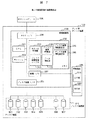
本発明の第1の実施形態のシステム構成を図1〜3を用いて説明する。図1において、100はホストコンピュータ、123はアレイ型ディスク装置、200はアレイ型ディスク装置の管理制御部、310はディスク装置群、500は管理端末である。
(First embodiment)
The first embodiment of the present invention is to achieve the first object of the problem to be solved by the invention.
In other words, in an array type disk device that performs preventive copying to a spare disk device, reliability that reduces the probability of a double failure of a disk device, also referred to as a disk drive or simply a drive, without increasing the cost of the spare disk device. It is to provide a high array type disk device.
(1) Description of Configuration The system configuration of the first embodiment of the present invention will be described with reference to FIGS. In FIG. 1, 100 is a host computer, 123 is an array type disk device, 200 is a management control unit of the array type disk device, 310 is a disk device group, and 500 is a management terminal.
アレイ型ディスク装置123、ホストコンピュータ100、管理制御部200、ディスク装置群310、および、管理端末500はそれぞれ図のように結線する。
The array
アレイ型ディスク装置123は管理制御部200として以下を含む。201は管理制御部200の制御を実施するCPU、202はメモリ、203はユーザのデータをバッファリングするキャッシュ、204はホストとのデータの送受信を行うホストI/F、205はディスク装置群310との送受信を行うドライブI/F、207は管理端末500との制御情報の送受信を行う管理I/Fであり、それぞれを結線する。メモリ202は、ディスクアレイを制御するレイド(RAID)制御部210と、ディスク装置群310の管理を行うディスク装置管理部230と、ディスク装置群310の運用パラメータや運用状況などディスク装置情報を記録するディスク装置管理テーブル240と、管理端末500からの入力を受けてディスク装置情報を設定するディスク装置情報設定部250と、管理端末500への出力としてディスク装置情報を通知するディスク装置情報通知部260とを有する。
The array
ディスク装置群310は、ディスク装置301〜307とからなる。ディスク装置301〜305は、従来の技術で述べたようなディスクの並列動作と冗長性の付加により、性能と信頼性を強化したディスクアレイグループを構成しており、この状態をディスク装置301〜305の組でレイド(RAID)グループとなるディスクアレイグループを構成していると呼ぶこととする。ディスク装置306、307は、ディスクアレイ(RAID)グループを構成するディスクが故障したときに替わりにディスクアレイグループに組み入れるためのスペアディスク装置である。
The
管理端末500は、ユーザからのディスク装置301〜305への設定を入力する入力部510と、ディスク装置301〜305の情報をユーザに示す出力部520とからなる。入力部510からは、ディスク装置管理テーブル240へのディスク装置運用パラメータを入力する。出力部520は、ディスク装置管理テーブル240のディスク装置運用状況を出力表示する。
The
図2は、ディスク装置管理テーブル240である。パラメータとしては、ディスク装置の識別番号を表す「ディスク装置No.」、ディスク装置の累積エラー回数を格納する「エラー回数カウンタ」、ディスク装置の累積エラー回数の指標として第1段階の値を示す「エラー回数規定値レベル1」、ディスク装置の累積エラー回数の指標として第2段階の値を示す「エラー回数規定値レベル2」、スペアディスク装置として運用されていることを示す「スペアビット」、ディスク装置の運用状況を示す「ディスク装置状況」、ディスク装置障害に対応するために使うスペアディスク装置との関連付けを示す「ペアディスク装置」を有する。
FIG. 2 shows the disk device management table 240. As parameters, “disk device No.” indicating the identification number of the disk device, “error counter” storing the cumulative error count of the disk device, and a first-stage value as an index of the cumulative error count of the disk device “ "Error count prescribed
「エラー回数規定値レベル1」には、対象となるディスク装置のエラー回数が累積し障害が発生する可能性が高くなった場合に、スペアディスク装置とのミラーリングを開始する契機を示す値を設定する。「エラー回数規定値レベル2」には、「エラー回数規定値レベル1」の値よりも高い値を設定し、対象となるディスク装置のエラー回数が累積し運用が継続できないとみなせる状況になったと判定する値とし、ディスク装置を閉塞させ、スペアディスク装置とのミラーリングを終了する契機を示す値を設定する。「スペアビット」には、該当ディスク装置がスペアディスク装置である場合はYESを、そうでない場合はNOを設定する。「エラー回数規定値レベル1」、「エラー回数規定値レベル2」、「スペアビット」の設定は、ユーザが管理端末500の入力手段510を用いて設定する。
“Error count specified
「ディスク装置状況」には、ディスク装置の運用状況として異常がないことを示す「正常」、エラー回数カウンタの値が「エラー回数規定値レベル1」に達し、スペアディスク装置とのミラーリングを実施していることを示す「ミラー」、エラー回数カウンタの値が「エラー回数規定値レベル2」に達し、該当ディスク装置を運用継続不可とみなしたことを示す「閉塞」のパラメータを設定する。「ペアディスク装置」には、ミラーリングするペアとなるディスク装置の「ディスク装置No.」を設定する。ディスク装置管理テーブル240の各パラメータ値は、ユーザ指示により管理端末500の出力手段520に出力表示する。
In “Disk device status”, “Normal” indicating that there is no abnormality in the operation status of the disk device, the error counter value reaches “error count specified
図3は、ディスク装置管理部230である。231は、ディスク装置のエラー発生状況を監視し、ディスク装置のエラー発生回数が「エラー回数規定値レベル1」を超えた場合にディスク装置とスペアディスク装置のミラーリング開始を指示し、「エラー回数規定値レベル2」を超えた場合はミラーリングを終了するように指示するエラー監視部である。232は、ディスク装置のエラー発生回数をカウントし、ディスク装置管理テーブル240の「エラー回数カウンタ」に積算したエラー発生回数を設定するエラーカウント部である。233は、管理端末500を使ってユーザが指定したパラメータをディスク装置管理テーブル240に設定するエラー回数規定値設定部である。234は、エラー監視部231の指示により、ディスク装置の運用状況をディスク装置管理テーブル240に設定するディスク状況設定部である。235は、あるディスク装置とスペアディスク装置へのアクセスをミラーリングするミラー部である。236はディスク装置の閉塞と該装置が行っていた処理のスペアディスク装置への移行を指示する閉塞移行監視部である。237は閉塞監視部の指示によりディスク装置の閉塞・移行を行う閉塞移行部である。
FIG. 3 shows the disk
以上が、本実施形態のアレイ型ディスク装置のシステム構成である。
(2)予防スペアコピー動作
従来の技術では、ディスク装置のエラー発生回数を監視し、ある規定値に達した場合にスペアディスク装置にコピーし、該当ディスク装置を閉塞させるのに対し、本実施形態では、規定値を2段階設け、第1段階の規定値レベル1に達した場合にスペアディスク装置とのミラーリングを開始する。その際、該当ディスク装置は閉塞させずに運用を継続する。第2段階の規定値レベル2に達した場合にミラーリングを解除し、該当ディスク装置を閉塞させスペアディスク装置にて運用を継続する。
The above is the system configuration of the array type disk device of the present embodiment.
(2) Preventive Spare Copy Operation In the conventional technique, the number of error occurrences of a disk device is monitored, and when a specified value is reached, copying to a spare disk device is performed and the corresponding disk device is blocked. Then, two levels of prescribed values are provided, and when the prescribed
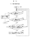
次に、予防スペアコピー動作を図4のフローチャートを用いて説明する。 Next, the preventive spare copy operation will be described with reference to the flowchart of FIG.
前提として、各ディスク装置301〜307のエラー発生状況は、エラーカウント部232によってカウントし、ディスク装置管理テーブル240に継続的に設定されているものとする。図4は、ディスクアレイグループ(RAID)グループを構成するディスク装置301〜305に対して、独立に実施するものとする。
It is assumed that the error occurrence status of each of the
まず、エラー監視部231が、監視の対象としている該当ディスク装置のディスク装置管理テーブル240の「エラー回数カウンタ」の値が「エラー回数規定値レベル1」に達したかどうかを判定する(ステップ1001)。達していない場合は、引き続きステップ1001を繰り返す。達していた場合は、「スペアビット」がYesとなっているディスク装置を探索し、スペアディスク装置を選択する(ステップ1002)。その後、エラー監視部231は、選択したスペアディスク装置の「ペアディスク装置」に該当ディスク装置のディスク装置番号を設定し(ステップ1003)、対象となるディスク装置の「ペアディスク装置」にスペアディスク装置の番号を設定する(ステップ1004)。次に、エラー監視部231は、対象となるディスク装置とスペアディスク装置の「ディスク装置状況」をミラーのステータスに設定し(ステップ1005)、ミラー部235に指示を送り、該当ディスク装置とスペアディスク装置のミラーリングを開始する(ステップ1006)。
First, the
ここで、図2にディスク装置管理テーブル240の設定状況の例を示す。「ディスク装置No.」として0〜4にてディスクアレイ(RAID)グループを構成するディスクアレイにおいて、「ディスク装置No.」の4のディスク装置が「エラー回数規定値レベル1」である「50」という値を超えた「エラー回数カウンタ」の値60となっている。この状態はすでにスペアディスク装置である「ディスク装置No.」の5とのミラーリングが開始された状況であり、「ディスク装置No.」の4のディスク装置の「ディスク装置状況」はミラー、「ペアディスク装置」はNo.5となっており、「ディスク装置No.」の5のディスク装置の「ディスク装置状況」はミラー、「ペアディスク装置」はNo.4となっている。
Here, FIG. 2 shows an example of the setting status of the disk device management table 240. In the disk array constituting the disk array (RAID) group with 0 to 4 as “disk device No.”, the four disk devices of “disk device No.” are “error count prescribed
図4に戻り、次のステップとして、エラー監視部231が、監視の対象としている該当ディスク装置のディスク装置管理テーブル240の「エラー回数カウンタ」の値が「エラー回数規定値レベル2」に達したかどうかを判定する(ステップ1007)。達していない場合は、引き続きステップ1007を繰り返す。達していた場合は、閉塞移行監視部が閉塞開始およびスペアディスク装置への移行開始を指示し、対象となるディスク装置の「ディスク装置状況」を閉塞のステータスに、スペアディスク装置の「ディスク装置状況」を正常のステータスに設定し(ステップ1008)、ミラー部235に指示を送り、該当ディスク装置とスペアディスク装置のミラーリングを終了し、対象ディスク装置に行っていた処理をスペアディスク装置に移行する(ステップ1009)。上記の閉塞及び移行は閉塞移行部により行う。スペアディスク装置がどのディスクから移行したかは「ペアディスク装置」の値を参照すればよい。
Returning to FIG. 4, as the next step, the
以上が、予防スペアコピー動作である。
(3) 効果
従来の技術では、ディスク装置のエラー発生回数を監視し、ある規定値に達した場合にスペアディスク装置にコピーし、該当ディスク装置を閉塞させるのに対し、本実施形態では、規定値を2段階設け、第1段階の規定値に達した場合にスペアディスク装置とのミラーリングを開始する。その際、該当ディスク装置は閉塞させずに運用を継続する。第2段階の規定値に達した場合にミラーリングを解除し、該当ディスク装置を閉塞させスペアディスク装置にて運用を継続する。
The above is the preventive spare copy operation.
(3) Effect According to the conventional technique, the number of error occurrences of a disk device is monitored, and when a certain specified value is reached, the disk device is copied to a spare disk device and the corresponding disk device is blocked. Two levels are provided, and mirroring with the spare disk device is started when the specified value in the first stage is reached. At that time, the operation is continued without blocking the disk device. When the specified value in the second stage is reached, the mirroring is canceled, the corresponding disk device is blocked, and the operation is continued in the spare disk device.
また、ミラーリングしているだけであるため、仮に該当ディスク装置以外のディスク装置で、第2段階の規定値を超えるようなエラー発生状況となった場合、該当ディスク装置のミラーリングを解除し、スペアディスク装置を他のディスク装置のスペアとして使用することも可能である。 Also, because it is only mirrored, if a disk device other than the relevant disk device causes an error that exceeds the specified value in the second stage, the mirroring of the relevant disk device is canceled and the spare disk It is also possible to use the device as a spare for another disk device.
例えば、図2のディスク装置管理テーブル240の例が示すように、「ディスク装置No.」の4のディスク装置が「エラー回数規定値レベル1」である「50」という値を超えた「エラー回数カウンタ」の値60となっている場いいで、「ディスク装置No.」4のディスクと、「ディスク装置No.」の5のディスク装置が60となっている場合で、「ディスク装置No.」の5のディスク装置がミラーリングされている状態を想定する。この状態で、「ディスク装置No.」の0のディスク装置の「エラー回数カウンタ」の値が、「エラー回数規定値レベル2」である「90」という値を超えた場合、エラー監視部231が「ディスク装置No.」の4と5のミラーリングを解除し、「ディスク装置No.」の5のディスク装置を「ディスク装置No.」の0のディスクのスペアとして使用することができる。「ディスクNo.」の0のディスクはエラー発生頻度が高くなり、故障状態となりそうなディスク装置であり、故障状態となる前にデータをスペアディスク装置にコピーする。
For example, as shown in the example of the disk device management table 240 in FIG. 2, the “disk device No.” 4 disk devices exceed the value “50” which is “error count prescribed
このように、他のディスク装置のスペアディスク装置としての転用が可能であるため、第1段階の規定値は、従来の技術で規定していた値よりも、低い値とすることが可能で、ディスクの2重障害に対する耐性を向上できる。また、スペアディスクの転用が可能であるため、第1段階で閉塞させる従来の技術と比較して、スペアディスク装置のコストを抑止できる。 In this way, since the other disk device can be diverted as a spare disk device, the specified value in the first stage can be set to a value lower than the value specified in the prior art, It is possible to improve the tolerance against a double failure of the disk. Further, since the spare disk can be diverted, the cost of the spare disk device can be suppressed as compared with the conventional technique that is blocked in the first stage.
また、第1段階でミラーリングしておくので、第2段階の規定値に達したときに即時にスペアディスク装置への切り替えが可能であり、ディスク装置の2重障害に対する耐性を向上できる。 Further, since the mirroring is performed in the first stage, it is possible to immediately switch to the spare disk device when the specified value in the second stage is reached, and the tolerance of the disk device against double failure can be improved.
以上、本実施形態により、スペアディスク装置に予防コピーしておくディスクアレイにおいて、スペアディスク装置のコストを上げることなく、ディスク2重障害の確率を下げる信頼性の高いアレイ型ディスク装置を提供することができる。 As described above, according to this embodiment, in a disk array to be proactively copied to a spare disk device, a highly reliable array type disk device that reduces the probability of a double disk failure without increasing the cost of the spare disk device is provided. Can do.
(第2の実施形態)
第2の実施形態は、第1の実施形態と同様に、発明が解決しようとする課題の第1の目的を解決するためのものである。すなわち、スペアディスク装置に予防コピーしておくアレイ型ディスク装置において、スペアディスク装置のコストを上げることなく、ディスク装置の2重障害の確率を下げる信頼性の高いアレイ型ディスク装置を提供することである。
(1)構成の説明
本発明の第2の実施形態のシステム構成を説明する。簡単化のため、第1の実施形態との違いについてのみ述べる。システム構成は第1の実施形態と同様に図1である。
ディスク装置群310は、ディスク装置301から307とからなる。ディスク301〜305は、従来の技術で述べたようなディスク装置の並列動作と冗長性の付加により、性能と信頼性を強化したディスクアレイを構成しており、この状態をディスク装置301から305の組でディスクアレイ(RAID)グループを構成していると呼ぶこととする。ディスク装置306,307はディスクアレイ(RAID)グループを構成するディスク装置が故障したときに替わりにディスクアレイ(RAID)グループに組み入れるためのスペアディスク装置であるが、第1の実施形態との違いはエラー発生回数が少ないうちから、エラー発生回数の多いディスク装置に対してミラーリングを行っておくことである。ミラーリングを行うスペアディスク装置は全スペアディスク装置、もしくは、2台以上のスペアディスク装置があることが望ましいが1台のスペアディスクでもよい。また、ミラーリングしているディスク装置以外のディスク装置で、ミラーリングをしているディスク装置のエラー発生回数を超える状況になった場合には、ミラーリングをしているディスク装置のうちエラー発生回数が最も低いディスク装置のミラーリングを解除し、解除したスペアディスク装置をエラー発生回数が高くなったディスク装置に対するミラーリングを行うスペアディスク装置として使用する。ミラーリングを組むディスク装置をダイナミックに切り替えていくことから、この動作をダイナミックミラーリング動作と呼ぶこととする。
(Second Embodiment)
Like the first embodiment, the second embodiment is for solving the first object of the problem to be solved by the invention. That is, by providing a highly reliable array type disk device that reduces the probability of double failure of a disk device without increasing the cost of the spare disk device in an array type disk device that is proactively copied to a spare disk device. is there.
(1) Description of Configuration A system configuration according to the second embodiment of the present invention will be described. For the sake of simplicity, only differences from the first embodiment will be described. The system configuration is FIG. 1 as in the first embodiment.
The
図5は、第2の実施形態のディスク装置管理テーブル240であり、パラメータは、第1の実施形態の図2と同様である。第1の実施形態との違いは、「エラー回数規定値レベル1」には、対象となるディスク装置のエラー回数が累積し障害が発生する確率が高くなった場合に、全ディスク装置の「エラー回数カウンタ」を調査し、スペアディスク装置を「エラー回数カウンタ」の値の高い方のディスク装置とミラーリングを開始する契機を示す値を設定する。
FIG. 5 is a disk device management table 240 of the second embodiment, and parameters are the same as those of FIG. 2 of the first embodiment. The difference from the first embodiment is that the “error count prescribed
「ディスク装置状況」には、ディスク装置の運用状況として異常がないことを示す「正常」、スペアディスク装置とのミラーリングを実施していることを示す「ミラー」、エラー回数カウンタの値が「エラー回数規定値レベル2」に達し、該当ディスク装置を運用継続不可とみなしたことを示す「閉塞」のパラメータを設定する。
In “Disk Device Status”, “Normal” indicating that there is no abnormality in the operating status of the disk device, “Mirror” indicating that mirroring with the spare disk device is being performed, and the value of the error count counter is “Error” The “blocking” parameter is set to indicate that the number of times specified
第2の実施形態においては、ディスク装置管理部230は図3であり、231は、ディスク装置のエラー発生状況を監視し、ディスク装置のエラー発生回数が「エラー回数規定値レベル1」を超えた場合、全ディスク装置の「エラー回数カウンタ」を調査し、スペアディスク装置を「エラー回数カウンタ」の値の高い方のディスク装置とミラーリングを開始し、「エラー回数規定値レベル2」を超えた場合はミラーリングを終了するよう指示するエラー監視部である。
以上が、本実施形態のシステム構成である。
In the second embodiment, the disk
The above is the system configuration of the present embodiment.
(2)ダイナミックミラーリング動作
従来の技術では、ディスク装置のエラー発生回数を監視し、ある規定値に達した場合にスペアディスク装置にコピー(ミラーリング)し、該当ディスク装置を閉塞させるのに対し、本実施形態では、エラー発生回数が少ないうちから、エラー発生回数の多いディスク装置に対しミラーリングを行っておき、ミラーリングを組むディスク装置をエラー発生回数に応じて、ダイナミックに切り替えていく。
(2) Dynamic mirroring operation In the conventional technology, the number of error occurrences of a disk device is monitored, and when it reaches a specified value, it is copied (mirrored) to a spare disk device, and this disk device is blocked. In the embodiment, since the number of error occurrences is small, the disk device having a large number of error occurrences is mirrored, and the disk device for which mirroring is assembled is dynamically switched according to the number of error occurrences.
次に、ダイナミックミラーリング動作を図6−1及び図6−2のフローチャートを用いて説明する。前提として、各ディスク装置301から307のエラー発生状況は、エラーカウント部232によってカウントし、ディスク装置管理テーブル240に継続的に設定されているものとする。
Next, the dynamic mirroring operation will be described with reference to the flowcharts of FIGS. 6-1 and 6-2. It is assumed that the error occurrence status of each
まず、エラー監視部231が、ディスク装置管理テーブル240の「エラー回数カウンタ」の値が「エラー回数規定値レベル1」に達したディスク装置があるかどうかを判断する(ステップ1501)。この場合、「エラー回数規定値レベル1」に達したディスク装置はどのディスク装置であってもよい.「エラー回数カウンタ」の値が「エラー回数規定値レベル1」に達したディスク装置がない場合は、引き続きステップ1501を繰り返す。
First, the
「エラー回数規定値レベル1」に達したディスク装置がある場合は、全ディスク装置の「エラー回数カウンタ」の値を調査する(ステップ1502)。次に、エラー監視部231は、「スペアビット」がYESとなっているディスク装置を探索し、「ミラー状況」がミラーとなっていないディスク装置、即ちペアを組んでいないスペアディスク装置があるかどうかを判定する(ステップ1503)。
If there is a disk device that has reached “error count prescribed
ペアを組んでいないスペアディスク装置がある場合は、エラー監視部231が、ペアを組んでいないディスク装置のうち、「エラー回数カウンタ」の値が最大のものをペアリング対象に選定し(ステップ1504)、スペアディスク装置の「ペアディスク装置」に対象となるディスク装置番号を設定し(ステップ1505)、対象となるディスク装置の「ペアディスク装置」にスペアディスク装置番号を設定し(ステップ1506)、対象となるディスク装置とスペアディスク装置の「ディスク装置状況」をミラーのステータスに設定し(ステップ1507)、ミラー部235にミラー開始を指示し(ステップ1508)、ステップ1503に戻る。
ペアを組んでいないスペアディスク装置がない場合は、ステップ1509に移行する。
When there is a spare disk device that does not form a pair, the
If there is no spare disk device that does not form a pair, the process proceeds to step 1509.
ここで、図5にディスク装置管理テーブル240の設定状況の例を示す。「ディスク装置No.」として0〜4にてレイド(RAID)グループを構成するディスクアレイにおいて、「ディスク装置No.」の2のディスクが「エラー回数規定値レベル1」である「30」という値を超えた「エラー回数カウンタ」の値35となっている。この状態はすでにステップ1509まで移行した状況であり、スペアディスク装置である「ディスク装置No.」の5と「ディスク装置No.」の2のミラーリングが開始された状況であり、「ディスク装置No.」の2の「ディスク装置状況」はミラー、「ペアディスク装置」はNo.5となっており、「ディスク装置No.」の5のディスク装置の「ディスク装置状況」はミラー、「ペアディスク装置」はNo.2となっている。また、2番目に「エラー回数カウンタ」の値が大きかった「ディスク装置No.」の4のディスク装置とペアディスク装置である「ディスク装置No.」の6のミラーリングが開始された状況であり、「ディスク装置No.」の4のディスク装置の「ディスク装置状況」はミラー、「ペアディスク装置」はNo.6となっており、「ディスク装置No.」の6のディスクの「ディスク装置状況」はミラー、「ペアディスク装置」はNo.4となっている。
Here, FIG. 5 shows an example of the setting status of the disk device management table 240. In the disk array that constitutes a RAID group with 0 to 4 as “disk device No.”, the value “30” in which the two disks of “disk device No.” are “error count prescribed
図6−2に戻り、次のステップ1509として、エラー監視部231が、ペアを組んでいないディスク装置のうち、ペアを組んでいるディスク装置を超える「エラー回数カウンタ」の値となったディスク装置があるかどうか判定する(ステップ1509)。
Returning to FIG. 6B, as the
該当のディスク装置がある場合は、エラー監視部231が、ペアを組んでいないディスク装置のうち、ペアを組んでいるディスク装置を超える「エラー回数カウンタ」の値となったディスクをペアリング対象に選定し(ステップ1510)、ペアを組んでいるディスクのうち、「エラー回数カウンタ」の値が最小のディスクにおけるペアリングを解除し(ステップ1511)、ペアリングを解除したスペアディスク装置の「ペアディスク装置」に対象となるディスク装置番号を設定し(ステップ1512)、対象となるディスク装置の「ペアディスク装置」にスペアディスク装置番号を設定し(ステップ1513)、対象となるディスク装置とスペアディスク装置の「ディスク装置状況」をミラーのステータスに設定し(ステップ1513)、ミラー部235にミラー開始を指示し(ステップ1515)、ステップ1509に戻る。
When there is a corresponding disk device, the
ここで、図5のディスク装置管理テーブル240の設定状況の例を用いて、ステップ1509からステップ1515を説明する。スペアディスク装置である「ディスク装置No.」の5と「ディスク装置No.」の2のミラーリングが実施され、スペアディスク装置である「ディスク装置No.」の6と「ディスク装置No.」の4のミラーリングが実施されている状況を示している。
Here,
この状況において、例えば、「ディスク装置No.」の0のディスク装置の「エラー回数カウンタ」の値が、ミラーリングしている「ディスク装置No.」のディスク装置の値を超える25となった場合を想定する。この場合、ステップ1509でいうところのYesの状況であり、次のミラーリング対象を「ディスク装置No.」の0のディスク装置とし、ミラーリングしているディスク装置のうち「エラー回数カウンタ」の値が最小の「ディスク装置No.」の4のペアリングを解除し、ペアを解除したスペアディスク装置である「ディスク装置No.」の6と、新規にミラーリングの対象となった「ディスク装置No.」の0のディスク装置のミラーリングを実施するように動作する。
In this situation, for example, the case where the value of the “error counter” of the disk device “0” of “disk device No.” is 25, which exceeds the value of the disk device of “disk device No.” being mirrored. Suppose. In this case, the status is Yes in
図6−2に戻り、ステップ1509においては、ペアを組んでいないディスク装置のうち、ペアを組んでいるディスク装置を超える「エラー回数カウンタ」の値となったディスク装置がない場合はエラー監視部231が、監視の対象としているディスク装置の「エラー回数カウンタの値」が「エラー回数規定値レベル2」に達したかどうか判定する(ステップ1516)。達していない場合は、ステップ1509に戻る。達していた場合は、対象となるディスク装置の「ディスク装置状況」を関連のステータスに、スペアディスク装置の「ディスク装置状況」を正常のステータスに設定し(ステップ1517)、ミラー部235に指示を送り、該当ディスク装置とスペアディスク装置のミラーリングを終了し、対象ディスク装置に行っていた処理をスペアディスク装置に移行し(ステップ1518)、ステップ1509に戻る。スペアディスク装置がどのディスク装置に移行したかは「ペアディスク装置」の値を参照すればよい。
以上がダイナミックミラーリングの動作である。
Returning to FIG. 6-2, in
The above is the operation of dynamic mirroring.
なお、「エラー回数規定値レベル1」の値を0にしておき、当初からステップ1502移行のダイナミックミラーリング動作を実施してもよい。
また、ステップ1509における判定基準を、ペアを組んでいないディスク装置のうち、ペアを組んでいるディスク装置中の「エラー回数カウンタ」の最大値を超えたディスク装置があるかどうかの判定としてもよい。または、ペアを組んでいるディスク装置の「エラー回数カウンタ」の値から導かれる中間値、平均値等の値を超えたディスク装置があるかどうかの判定としてもよい。
Note that the value of “error count prescribed
Further, the determination criterion in
(3)効果
従来の技術では、ディスク装置のエラー発生回数を監視し、ある規定値に達した場合にスペアディスク装置にコピーし、該当ディスク装置を閉塞させるのに対し、本実施形態では、エラー発生回数が少ないうちから、エラー発生回数の多いディスク装置に対してミラーリングを行っておき、ミラーリングを組むディスク装置をエラー発生回数に応じて、ダイナミックにきりかえていくため、第2段階の規定値に達したときに即時にスペアディスク装置への切り替えができる確率が上がり、ディスク装置の2重障害に対する耐性を向上できる。
(3) Effect According to the conventional technique, the number of error occurrences of a disk device is monitored, and when a specified value is reached, copying to a spare disk device is performed and the corresponding disk device is blocked. Since the number of occurrences is small, mirroring is performed on the disk device with a large number of error occurrences, and the disk device that forms the mirroring is dynamically changed according to the number of error occurrences. The probability of being able to immediately switch to the spare disk device when the value reaches the value increases, and the tolerance to the double failure of the disk device can be improved.
なお、ダイナミックミラーリングを行うディスク装置を1つのアレイディスク(RAID)グループに対して行うよう記載したが、アレイ型ディスク装置全体にあるアレイディスク(RAID)グループに対して、アレイ型ディスク装置内にある全スペアディスク装置を用いてダイナミックミラーリングを実施してもよい。 In addition, although it described that the disk device which performs dynamic mirroring was performed with respect to one array disk (RAID) group, it exists in an array type disk device with respect to the array disk (RAID) group in the whole array type disk device. Dynamic mirroring may be performed using all spare disk devices.
(第3の実施形態)
第3の実施形態は、発明が解決しようとする課題の第2の目的を解決するためのものである。
すなわち、ディスクアレイ(RAID)グループを形成する1台のディスク装置が故障状態になったアレイ型ディスク装置において、ディスク2重障害の確率を低減する信頼性の高いアレイ型ディスク装置を提供することである。
(Third embodiment)
The third embodiment is for solving the second object of the problem to be solved by the invention.
That is, by providing a highly reliable array type disk device that reduces the probability of a double disk failure in an array type disk device in which one disk device forming a disk array (RAID) group has failed. is there.
(1) 構成の説明
本発明の第3の実施形態の装置構成を図7〜9を用いて説明する。簡単化のため、第1の実施形態との違いについてのみ述べる。図7においては図1の構成に加え、ディスク装置が閉塞し、ディスクアレイ(RAID)グループを構成する他のディスク装置からスペアディスク装置にデータを復元するデータ復旧部270をメモリ202に設置する。
(1) Description of Configuration An apparatus configuration according to the third embodiment of the present invention will be described with reference to FIGS. For the sake of simplicity, only differences from the first embodiment will be described. 7, in addition to the configuration of FIG. 1, the disk device is blocked, and a
また、図7のディスク装置管理テーブル240が所持するパラメータは、図2の場合と比較してエラー回数規定値レベル2を除いたものである。また、以下の点で格納内容が異なる。
Further, the parameters possessed by the disk device management table 240 of FIG. 7 are those obtained by removing the error count prescribed
「エラー回数規定値レベル1」には、対象となるディスク装置のエラー回数が累積し障害が発生する可能性が高くなった場合に、スペアディスク装置にコピーを開始する契機を示す値を設定する。コピー終了後、対象となるディスク装置の処理はスペアディスク装置に移行するが、データ復旧部270が実施する対象ディスク装置からの読み出しは許可する。
“Error count prescribed
「ディスク装置状況」には、ディスク装置の運用状況として異常がないことを示す「正常」、エラー回数カウンタの値が「エラー回数規定値レベル1」に達し、スペアディスク装置にコピーしている状態である「コピー」、スペアディスク装置にコピーが終了し、データ復旧手段270が実施する対象ディスク装置からの読み出しは許可する状態である「仮閉塞」、コピーが終了した後の「閉塞」、アレイディスク(RAID)グループを構成する他のディスク装置からスペアディスク装置にデータを復元する処理」」には、コピーするペアとなるディスク装置の「ディスク装置No.」を設定する。
The “disk device status” is “normal” indicating that there is no abnormality in the operation status of the disk device, the error count counter value has reached “error count prescribed
また、図9は、第3の実施形態のディスク装置管理部230であり、図3のミラー部235に替わり、236のコピー部を有する。231のエラー監視部は、ディスクのエラー発生状況を監視し、ディスク装置のエラー発生回数が「エラー回数規定値レベル1」を超えた場合にディスク装置からスペアディスク装置へのコピー開始を指示し、コピー中は仮閉塞のステータスにし、コピー終了後は、閉塞のステータスにする。236のコピー部は、あるディスクのデータをスペアディスクにコピーする。
以上が、本実施形態のシステム構成である。
FIG. 9 shows a disk
The above is the system configuration of the present embodiment.
(2)セクタ障害復旧動作
本実施形態では、あるセクタの読み出しができなくなり、ディスクアレイ(RAID)グループを構成する他のディスク装置からスペアディスク装置にデータを復旧することになった状況において、さらに、ディスクアレイ(RAID)グループを構成する他のディスク装置のあるセクタが読み出せなくなるディスク2重障害のケースでのデータ復旧の可能性を向上させる。あるセクタの読み出しができなくなったディスク装置はデータ復旧部270が実施する読み出しについては許可する仮閉塞状態としておく。
(2) Sector failure recovery operation In the present embodiment, in a situation where a sector cannot be read and data is recovered from another disk device constituting a disk array (RAID) group to a spare disk device, This improves the possibility of data recovery in the case of a double disk failure in which a certain sector of another disk device constituting the disk array (RAID) group cannot be read. A disk device in which reading of a certain sector cannot be performed is set in a temporarily blocked state in which reading performed by the
次に、セクタ障害復旧動作を図10のフローチャートを用いて説明する。
前提として、各ディスク装置301〜307のエラー発生状況は、エラーカウント手段232によってカウントし、ディスク装置管理テーブル240に継続的に設定されているものとする。図10は、ディスクアレイ(RAID)グループを構成するディスク装置301〜305に対して、独立に実施するものとする。また、ディスクアレイ(RAID)グループを構成する「ディスク装置No.」の4は、エラー回数が多くなっていると同時にあるセクタが読み出せなくなっており、エラー回数カウンタにかかわらず、仮閉塞状態としている。「ディスク装置No.」の0〜3を用いて、スペアディスク装置である「ディスク装置No.」の5にディスクアレイ(RAID)の冗長性を使ってデータを復旧している状況を想定する。この状況において、「ディスク装置No.」の0のあるセクタが読み出せなくなり、「ディスク装置No.」の4の同一セクタからデータを読み出し、ディスクアレイ(RAID)グループの復旧をするものと想定する。
Next, the sector failure recovery operation will be described with reference to the flowchart of FIG.
As a premise, it is assumed that the error occurrence status of each of the
まず、データ復旧部270が、「ディスク装置No.」の0〜3のデータをもとに、「ディスク装置No.」の5のスペアディスク装置に、「ディスク装置No.」の4相当のデータ復旧処理を開始する(ステップ2001)。次に、データ復旧部270は、復旧が終了したかどうかを判定し(ステップ2002)、終了した場合は復旧対象となる「ディスク装置No.」の4の処理をスペアディスク装置に移行し(ステップ2003)、処理を終了する(ステップ2004)。終了していない場合は、復旧に使用している「ディスク装置No.」の0〜3のディスク装置にセクタが読み出せないセクタ障害があるかどうかを判定する(ステップ2005)。セクタ障害がない場合は、引き続きステップ2002を繰り返す。セクタ障害がある場合は、仮閉塞となっている「ディスク装置No.」の4の同一セクタから読み出しを試みる(ステップ2006)。データ復旧部270は、読み出しが成功したかどうかの判定を行い(ステップ2007)、成功した場合は読み出したセクタの内容をもとに復旧処理を実施し(ステップ2008)、ステップ2002に戻る。失敗した場合は、対応セクタをデータロスト扱いにし(ステップ2009)、ステップ2002に戻る。
First, the
以上が、セクタ障害復旧動作である。 The above is the sector failure recovery operation.
(3)セクタ障害復旧動作時のライト動作
前提として、各ディスク装置301〜307のエラー発生状況は、エラーカウント部232によってカウントし、ディスク装置管理テーブル240に継続的に設定されているものとする。図1は、ディスク装置301〜305により構成するディスクアレイ(RAID)グループ全体に対して実施するものとする。また、ディスク装置301〜305によりディスクアレイ(RAID)グループを構成しており、各ディスク装置内にはデータとパリティが格納されており、パリティとパリティを算出するためのデータの組をストライプセットと呼ぶこととする。
(3) Write Operation during Sector Failure Recovery Operation As a premise, it is assumed that the error occurrence status of each
図11において、まず、管理制御部200がホスト100からの書き込み要求を受け取ると、ディスクアレイ(RAID)制御部210は、書き込み先が仮閉塞しているディスク装置かどうかを判定する(ステップ2501)。
In FIG. 11, first, when the
書き込み先が仮閉塞ディスク装置の場合、ステップ2502以降の処理となる。ここで仮閉塞ディスク装置をディスク装置305、書き込ムデータの同一ストライプセットのパリティが格納されているディスク装置をディスク装置301とする。まずディスクアレイ(RAID)制御部210は、仮閉塞しているディスク装置305とパリティが格納されているディスク装置301以外のディスク装置302から304から書き込むデータに対応する同一ストライプセットのデータを読み出す(ステップ2502)。次に、書き込みデータとステップ2502で読み出したデータの排他的論理和を算出し、新パリティを生成する(ステップ2503)。次に、書き込むデータを仮閉塞ディスク装置であるディスク装置305に書き込み(ステップ2504)、新パリティをパリティが格納されているディスク装置301に格納し(ステップ2505)、処理を終了する。
When the write destination is a temporary block disk device, the processing from
書き込み先が仮閉塞しているディスク装置でない場合、ステップ2507以降の処理となる。ディスクアレイ(RAID)制御部210は、書き込むデータのストライプセットのパリティが仮閉塞しているディスク装置にあるかどうか判定する(ステップ2507)。
If the write destination is not a temporarily blocked disk device, the processing from
パリティが仮閉塞しているディスク装置にある場合、ステップ2508以降の処理となる。ここで、仮閉塞しているディスク装置をディスク装置305、書き込むデータが格納されているディスク装置を301とする。まず、ディスクアレイ(RAID)制御部210は仮閉塞しているディスク装置305とデータが格納されているディスク装置301以外のディスク装置302空04から書き込むデータに対応する同一ストライプセットのデータを読み出す(ステップ2508).次に、書き込みデータとステップ2508で読み出した同一ストライプセットのデータの排他的論理和を算出し、新パリティを生成する(ステップ2509)。次に、書き込むデータをディスク装置301に書き込み(ステップ2510)、新パリティをパリティが格納されている仮閉塞しているディスク装置であるディスク装置305に格納し(ステップ2511)、処理を終了する。
If the parity is in the disk device that is temporarily blocked, the processing from
パリティが仮閉塞しているディスク装置にない場合、ステップ2512以降の処理となる。ここで仮閉塞しているディスク装置をディスク装置305、書き込むデータが格納されているディスク装置をディスク装置301、同一ストライプセットのパリティが格納されているディスク装置をディスク装置302とする。まず、ディスクアレイ(RAID)制御部210は、書き込むデータの更新前のデータが格納されているディスク装置301から旧データを読み出し、更新前のパリティが格納されているディスク装置302から旧パリティを読み出す(ステップ2512)。次に、書き込みデータと、ステップ2512で読み出した旧データと旧パリティの排他的論理和を算出し、新パリティを生成する(ステップ2513).次に、書き込むデータをディスク装置301に書き込み(ステップ2514)、新パリティをパリティが格納されているディスク装置302に格納し(ステップ2515)、処理を終了する。
If the parity is not in the temporarily blocked disk device, the processing from
以上が、セクタ障害復旧中にホストより書き込み要求が来た場合のライト動作である。
なお、ディスクアレイ(RAID)の冗長性を利用してデータを復旧できることから、ステップ2504、ステップ2511での仮閉塞しているディスク装置への書き込みは省略してもよい。また、ステップ2504、ステップ2511での仮閉塞しているディスクへの書き込みに替えて、スペアコピーを実施しているスペアディスク装置に書き込むようにしてもよい。また、ステップ2504、ステップ2511での仮閉塞しているディスク装置への書き込みに加えて、スペアコピーを実施しているスペアディスク装置にも仮閉塞しているディスク装置に書き込み内容を書き込むようにしてもよい。
(4)効果
本実施形態では、あるセクタの読み出しができなくなり、ディスクアレイ(RAID)グループを構成する他のディスク装置からスペアディスク装置にデータを復旧することになった状況において、さらに、ディスクアレイ(RAID)グループを構成する他のディスク装置のあるセクタが読み出せなくなるディスク装置2重障害のケースでのデータ復旧の可能性を向上させることができる。
The above is the write operation when a write request is received from the host during sector failure recovery.
Since data can be recovered using the redundancy of the disk array (RAID), writing to the temporarily closed disk device in
(4) Effect In this embodiment, in a situation where a certain sector cannot be read and data is restored from another disk device constituting the disk array (RAID) group to the spare disk device, the disk array It is possible to improve the possibility of data recovery in the case of a disk device double failure in which a certain sector of another disk device constituting the (RAID) group cannot be read.
以上、本実施形態により、ディスクアレイ(RAID)グループを形成する1台のディスク装置が故障状態になったアレイ型ディスク装置において、ディスク装置2重障害の確率を下げる信頼性の高いアレイ型ディスク装置を提供することができる。 As described above, according to the present embodiment, in an array type disk device in which one disk device forming a disk array (RAID) group is in a failure state, a highly reliable array type disk device that reduces the probability of a double failure of the disk device. Can be provided.
なお、スペアディスク装置に予防コピーを行うことを前提として記載したが、予防コピーを行わないアレイ型ディスク装置においても、本実施形態は適用可能である。 Although the description has been made on the premise that preventive copying is performed on a spare disk device, the present embodiment can be applied to an array type disk device that does not perform preventive copying.
また、アレイ型ディスク装置の復旧開始の前提として、あるセクタ読み出しができなくなったディスクアレイ型ディスク装置の存在が復旧の契機であるとしたが、その他の条件であっても構わない。たとえば、エラー発生回数が規定値を超えたことにより、閉塞状態とみなしたことディスク装置の復旧を開始したという契機であってもよい。 In addition, as the premise for starting recovery of the array type disk device, the existence of the disk array type disk device that has become unable to read a certain sector is the trigger for recovery, but other conditions may be used. For example, when the number of error occurrences exceeds a specified value, it may be a trigger that recovery of the disk device is started because it is regarded as a blocked state.
(第4の実施形態)
第4の実施形態は、発明が解決しようとする課題の第3の目的を解決するためのものである。
すなわち、スペアディスク装置に予防コピーしておくアレイ型ディスク装置において、ディスクアレイ(RAID)グループを形成する複数のディスク装置の故障ポテンシャルが高くなっている状態において、ディスク装置2重障害の確率を下げる信頼性の高いアレイ型ディスク装置を提供することである。
(1) 構成の説明
本発明の第4の実施形態のアレイ型ディスク装置構成を図12、13を用いて説明する。簡単化のため、第3の実施形態との違いについてのみ述べる。アレイ型ディスク装置構成図としては、第2の実施形態の図7と同一である。ただし、データ復旧手段270の機能として、データ復旧中にセクタ障害があった場合に、かわりとなるセクタを読み出す機能は持たなくてもよい。
(Fourth embodiment)
The fourth embodiment is for solving the third object of the problem to be solved by the invention.
In other words, in an array type disk device that is proactively copied to a spare disk device, the probability of a disk device double failure is reduced when the failure potential of a plurality of disk devices forming a disk array (RAID) group is high. An object of the present invention is to provide a highly reliable array type disk device.
(1) Description of Configuration An array type disk device configuration according to the fourth embodiment of the present invention will be described with reference to FIGS. For simplicity, only differences from the third embodiment will be described. The configuration of the array type disk device is the same as FIG. 7 of the second embodiment. However, as a function of the data recovery means 270, when there is a sector failure during data recovery, there is no need to have a function of reading a substitute sector.
また、図12のディスク装置管理テーブル240は、所持するパラメータは図8と比較してエラー回数補助規定値を付加したものである。また、以下の点で図8と格納内容が異なる。 In addition, the disk device management table 240 in FIG. 12 has a parameter to which an error frequency auxiliary specified value is added in comparison with FIG. Further, the stored contents differ from FIG. 8 in the following points.
「エラー回数規定値レベル1」には、対象となるディスク装置のエラー回数が累積し障害が発生する可能性が高くなった場合に、スペアディスク装置にコピーを開始する契機を示す値を設定する。コピー終了後、対象となるディスク装置の処理はスペアディスク装置に移行し、対象となるディスク装置は閉塞状態とする。「エラー回数補助規定値」には、「エラー回数規定値レベル1」の値よりも低い値を設定し、ディスクアレイ(RAID)グループを構成するディスク装置のうち、複数のディスク装置がこの値に達すると、潜在的に同時に障害を起こす危険性が高いことを意味する値とする。
“Error count prescribed
「ディスク装置状況」には、ディスク装置の運用状況として異常がないことを示す「正常」、エラー回数カウンタの値が「エラー回数規定値レベル1」に達し、スペアディスク装置にコピーしている状態である「コピー」、スペアディスク装置にコピーが終了した後の「閉塞」、ディスクアレイ(RAID)グループを構成する他のディスク装置からスペアディスク装置にデータを復元する処理を実行中であることを示す「復旧中」の各パラメータを設定する。
The “disk device status” is “normal” indicating that there is no abnormality in the operation status of the disk device, the error count counter value has reached “error count prescribed
また、図13は、第4の実施形態のディスク装置管理手段230であり、図3のミラー部235に替わり、236のコピー部を有する。231のエラー監視部は、ディスク装置のエラー発生状況を監視し、ディスク装置のエラー発生回数が「エラー回数規定値レベル1」を超えた場合にディスク装置からスペアディスク装置へのコピー開始を指示し、コピー終了後は、閉塞のステータスにする。237は、「エラー回数規定値レベル1」の値を再設定するエラー回数規定値変更部である。
以上が、本実施形態のアレイ型ディスク装置構成である。
FIG. 13 shows a disk
The above is the configuration of the array type disk device of this embodiment.
(2)ディスク装置2重障害予防動作
本実施形態は、ディスクアレイ(RAID)グループを形成する複数のディスク装置の故障ポテンシャルが高くなっている状態において、スペアディスク装置への予防コピー開始契機となるエラー発生回数の規定値を動的に変更することでディスク装置2重障害の確率を下げるものである。
(2) Disk device double failure prevention operation This embodiment triggers the start of preventive copying to a spare disk device when the failure potential of a plurality of disk devices forming a disk array (RAID) group is high. By dynamically changing the specified value of the number of error occurrences, the probability of a disk device double failure is lowered.
次に、ディスク装置2重障害予防動作を図14のフローチャートを用いて説明する。 Next, the disk device double failure prevention operation will be described with reference to the flowchart of FIG.
前提として、各ディスク装置301〜307のエラー発生状況は、エラーカウント部232によってカウントし、ディスク装置管理テーブル240に継続的に設定されているものとする。図11は、ディスクアレイ(RAID)グループを構成するディスク装置301〜305に対して、独立に実施するものとする。また、ディスクアレイ(RAID)グループを構成する「ディスク装置No.」の1と3は、エラー回数が多くなっており、潜在的にディスク装置の2重障害のポテンシャルが高くなっている状態を想定する。
It is assumed that the error occurrence status of each of the
まず、エラー監視部231が、監視の対象としている該当ディスク装置のディスク装置管理テーブル240の「エラー回数カウンタ」の値が「エラー回数規定値レベル1」に達したかどうかを判定する(ステップ3001)。達した場合は、該当ディスク装置の内容をスペアディスク装置にコピーし、移行する処理を行う(ステップ3002)。達していない場合は、「エラー回数カウンタ」の値が「エラー回数補助規定値」に達したかどうかを判定する(ステップ3004)。達していない場合は、引き続きステップ3001を繰り返す。達していた場合は、同一ディスクアレイ(RAID)グループを構成する対象以外のディスク装置でエラー回数のカウンタの値が「エラー補助規定値」に達しているものがあるかどうかを判定する(ステップ3005)。達しているものがない場合は、引き続きステップ3001を繰り返す。達しているものがある場合は、ディスクアレイ(RAID)グループを構成する全ディスク装置の「エラー回数規定値レベル1」の値を下げ(ステップ3006)、引き続きステップ3001を繰り返す。
First, the
「エラー回数規定値レベル1」の値の再設定はエラー回数規定値変更部237で実施する。再設定する値は、「エラー回数規定値レベル1」と「エラー補助規定値」の中間値としておくなど任意の値でよい。また、ステップ3004、ステップ3005では、同一RAIDグループを構成する対象以外のディスク装置でエラー回数のカウンタの値が「エラー補助規定値」に達しているものがあるかどうかを判定基準としたが、たとえば、ディスクアレイ(RAID)グループを構成する全ディスク装置の「エラー回数カウンタ」の値の合計値を判定基準としてもよい。
以上が、ディスク装置2重障害予防動作である。
The value of “error count prescribed
The above is the disk device double failure prevention operation.
(3) 効果
本実施形態によれば、スペアディスク装置に予防コピーしておくアレイ型ディスク装置において、ディスクアレイ(RAID)グループを形成する複数のディスク装置の故障ポテンシャルが高くなっている状態において、ディスク装置2重障害の確率を下げる信頼性の高いアレイ型ディスク装置を提供することができる。
なお、第4の実施形態は、エラー回数の判断基準となる規定値を動的に変更するものであり、第1、第2、第3の実施形態と組み合わせて適用してもよい。
(3) Effect According to the present embodiment, in the array type disk device to be proactively copied to the spare disk device, the failure potential of the plurality of disk devices forming the disk array (RAID) group is high. It is possible to provide a highly reliable array type disk device that reduces the probability of a disk device double failure.
Note that the fourth embodiment dynamically changes a specified value that is a criterion for determining the number of errors, and may be applied in combination with the first, second, and third embodiments.
また、第1、第2の実施形態において、第3の実施形態のデータ復旧手段270を適用することで、ディスク装置障害を契機としたデータ復旧中における、あるディスク装置のセクタ読み出し障害にも対応することができる。 In the first and second embodiments, by applying the data recovery means 270 of the third embodiment, it is possible to cope with a sector read failure of a certain disk device during data recovery triggered by a disk device failure. can do.
(第5の実施形態)
次に、本発明の第5の実施形態を示す。第5の実施形態は、本発明が解決しようとする課題の第4の目的を達成するためのものである。
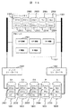
図15は本発明の第5の実施形態のアレイ型ディスク装置の構成を示す説明図である。本実施例のアレイ型ディスク装置は、ホストコンピュータ100とコマンド及びデータの入出力を行う複数のホストI/Fを具備した単一または複数のチェネルコントローラ(1101)とホストコンピュータとの入出力データを一時的に蓄えておくキャッシュメモリ(1301)とホストコンピュータの入出力データを記憶しておくディスク装置(1601〜1605)とディスク装置の制御を行うための単一または複数のディスク装置I/F1551を具備した単一または複数のディスクコントローラA(1401)と、同じく単一または複数のディスクドライブI/F1552を具備した単一または複数のディスクコントローラB(1402)がアクセス可能な共有メモリ1302と、チェネルコントローラ(1101)−キャッシュメモリ(1301)−共有メモリ1302−ディスクコントローラA及びB(1401、1402)間のデータ転送及び通信を行うためのシステム・バス(1201、1202)より構成される。
また、ディスク装置D1(1601)、D2(1602)、D3(1603)、P(1604)は、ディスクアレイ(RAID)構成により冗長度を有している。
(Fifth embodiment)
Next, a fifth embodiment of the present invention will be described. The fifth embodiment is for achieving the fourth object of the problem to be solved by the present invention.
FIG. 15 is an explanatory diagram showing the configuration of an array type disk device according to the fifth embodiment of the present invention. The array type disk device of this embodiment has input / output data between a host computer and a single or plural channel controllers (1101) having a plurality of host I / Fs for inputting / outputting commands and data to / from the
Further, the disk devices D1 (1601), D2 (1602), D3 (1603), and P (1604) have redundancy due to the disk array (RAID) configuration.
ホストコンピュータ(100)からライトデータを受領したチャネルコントローラ(1101)はキャッシュメモリ(1301)に退避すると共にディスクコントローラA(1401)またはディスクコントローラB(1402)に対して、キャッシュメモリ(1301)にあるライトデータをディスク装置(1601〜1604)に書き込むよう指示する。またホストコンピュータ(100)からデータリード要求を受領したチェネルコントローラはディスクコントローラA(1401)または、ディスクコントローラB(1402)に対し、ディスク装置(ドライブ)(1601〜1604)よりデータを読み出し、キャッシュメモリ(1301)に転送するよう指示する。指示を受けたディスクコントローラA(1401)またはディスクコントローラB(1402)はディスク装置(1601〜1604)よりデータを読み出し、キャッシュメモリ(1301)に転送したのち、チャネルコントローラ(1101)にデータ読み出し完了を報告する。報告をうけたチェネルコントローラ(1101)データをキャッシュ(1301)よりホストコンピュータ(100)に転送する。 The channel controller (1101) that has received the write data from the host computer (100) is saved in the cache memory (1301) and is in the cache memory (1301) with respect to the disk controller A (1401) or the disk controller B (1402). An instruction is given to write the write data to the disk devices (1601-1604). The channel controller that has received the data read request from the host computer (100) reads the data from the disk devices (drives) (1601-1604) to the disk controller A (1401) or the disk controller B (1402), and caches them. Instruct to transfer to the memory (1301). Upon receiving the instruction, the disk controller A (1401) or the disk controller B (1402) reads data from the disk devices (1601 to 1604), transfers the data to the cache memory (1301), and then completes the data reading to the channel controller (1101). Report. The received channel controller (1101) data is transferred from the cache (1301) to the host computer (100).
図16はディスク装置D1(1601)でリードエラーが発生した場合の本発明の二重障害発生を防止したデータ回復を説明する図である。 FIG. 16 is a diagram for explaining data recovery that prevents the occurrence of a double failure according to the present invention when a read error occurs in the disk device D1 (1601).
ディスク装置(ドライブ)D1(1601)上のデータD1D1(2001)のリードエラーを検出したディスクコントローラA(1401)またはディスクコントローラB(1402)は共有メモリ(1302)上のディスク装置(ドライブ)情報(2101)を更新し、リードエラーとなったディスク装置D1(1601)のデータの冗長データをディスク装置D2(1602)のデータD2D1(2002)、ディスク装置D3(1603)のデータデータD3D1(2003)、ディスク装置DP(1604)のデータデータPD1(2004)を読み出してキャッシュメモリ(1301)にそれぞれ、データD2D1(2302)、データD3D1(2303)、データPD1(2304)として転送したのち、データD2D1(2302)、データD3D1(2303)、データPD1(2304)を用いて冗長度計算により、ディスク装置D1(1601)のデータD1D1(2301)を回復し、キャッシュメモリ(1301)に格納する。 The disk controller A (1401) or the disk controller B (1402) that has detected the read error of the data D1 D1 (2001) on the disk device (drive) D1 (1601) is the disk device (drive) information on the shared memory (1302). (2101) is updated, the redundant data of the data of the disk device D1 (1601) in which a read error has occurred is changed to the data D2 D1 (2002) of the disk device D2 (1602), and the data data D3 D1 (disk device D3 (1603) 2003), data data P D1 (2004) of the disk device DP (1604) is read and transferred to the cache memory (1301) as data D2 D1 (2302), data D3 D1 (2303), and data P D1 (2304), respectively. After that, data D2 D1 (2302), data D3 D1 (2303) By redundancy calculation using data P D1 (2304), to recover data D1 D1 (2301) of the disk device D1 (1601), it is stored in the cache memory (1301).
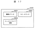
図17はディスク装置情報(2101)の構成要素を示す概略図である。
ディスク装置情報(2101)はデータリードエラーの発生回数を示す障害カウンタ(エラー発生回数カウンタ)(3001)、ディスク装置S(1605)へのデータ移行のコピー完了位置を示すコピーカウンタ(3002)、ディスク装置のリード/ライト可否情報等を示すディスク装置状態(3003)から構成され、障害カウンタ(エラー発生回数カウンタ)(3001)、コピーカウンタ(3002)の初期値は0、ディスク装置状態(3003)の初期値は“通常状態”である。
FIG. 17 is a schematic diagram showing components of the disk device information (2101).
The disk device information (2101) includes a failure counter (error occurrence number counter) (3001) indicating the number of occurrences of data read errors, a copy counter (3002) indicating the copy completion position of data migration to the disk device S (1605), a disk It consists of a disk device status (3003) indicating read / write availability information of the device, the initial value of the failure counter (error occurrence counter) (3001) and copy counter (3002) is 0, and the disk device status (3003) The initial value is “normal state”.
図18はディスクドライブ状態(2101)のディスク装置状態が“通常状態”でディスク装置D1(1601)でデータリードエラーが発生した場合の状態変更処理を示すフローチャートである。 FIG. 18 is a flowchart showing a state change process when the disk device state in the disk drive state (2101) is “normal state” and a data read error occurs in the disk device D1 (1601).
ディスクコントローラA(1401)またはディスクコントローラB(1402)はディスク装置D1(1601)からのデータリードがエラーになった場合、ステップ4001で前述のように共有メモリ(1302)にあるディスク装置D1(1601)に関するディスク装置情報(2101)の障害カウンタ(3001)を加算する。次にステップ4002で障害カウンタ(2101)がしきい値N1を超えたかどうか判定する。もししきい値N1を超えた場合、ディスクコントローラA(1401)または、ディスクコントローラB(1402)はディスク装置D1(1601)が近い将来完全にデータ読み出しができなくなる可能性があると考え、ステップ3003でディスク装置情報(2101)のディスク装置状態(3003)を“データ移行中”に変更し、ステップ3003でディスク装置D1(1601)のデータD1D1(2001)〜D1Dm(200n)をキャッシュメモリ(1301)上にデータD1D1(2301)〜D1Dm(230n)として読み込み、順次ディスク装置S(1605)に書き込むことにより、ディスク装置D1(1601)のデータをディスクドライブS(1605)に移行する。またこの時ディスク装置S(1605)にデータD1Dm(0≦Dm≦Dn)移行毎にディスクドライブ情報(2101)のコピーカウンタをDmに更新する。
If the disk controller A (1401) or the disk controller B (1402) has an error in reading data from the disk device D1 (1601), the disk device D1 (1601) in the shared memory (1302) as described above in step 4001. ) Is added to the failure counter (3001) of the disk device information (2101). Next, in
図19はディスク装置状態(2101)のディスク装置状態が“データ移行中”でディスク装置D1(1601)においてでデータリードエラーが発生した場合の状態変更処理を示すフローチャートである。 FIG. 19 is a flowchart showing the state change process when the disk device state (2101) is “data migration” and a data read error occurs in the disk device D1 (1601).
ディスクコントローラA(1401)またはディスクコントローラB(1402)はディスク装置D1(1601)からのデータリードがエラーになった場合、ステップ5001で前述のように共有メモリ(1302)にあるディスク装置D1(1601)に関するディスク装置情報(2101)の障害カウンタ(エラー発生回数カウンタ)(3001)を加算する。次にステップ5002で障害カウンタ(エラー発生回数カウンタ)(2101)が規定値N2を超えたかどうか判定する。規定値N2を越えていた場合、ディスク装置状態を“警告”に変更し、ステップ5004でデータ移行元のデータD1D1(2001)〜D1Dm(200n)をディスク装置D1(1601)から読み出すのではなく、ディスクアレイのレイド(RAID)機能を用いてディスク装置D2〜P(1602〜1604)から読み出して冗長度計算によって求める方式に変更する。
If the disk controller A (1401) or the disk controller B (1402) has an error in reading data from the disk device D1 (1601), the disk device D1 (1601) in the shared memory (1302) as described above in
図20はディスク装置情報(2101)のディスク装置状態(3003)が“通常状態”または“データ移行中”時におけるディスク装置D1(1601)のデータD1Dm(0≦Dm≦Dn)のリード方式を示すフローチャートである。 FIG. 20 shows a read method of data D1 Dm (0 ≦ Dm ≦ Dn) of the disk device D1 (1601) when the disk device state (3003) of the disk device information (2101) is “normal state” or “data migration in progress”. It is a flowchart to show.
ステップ6001でディスク装置D1(1601)からデータD1 Dmをリードしてキャッシュに転送する。ステップ6002でリードエラーがどうか判定し、リードエラーが発生した場合、ステップ6003で前述の通り冗長度を持つアレイディスクグループを構成するディスク装置D2(1602)、ディスク装置D3(1603)、ディスク装置P(1604)を用いて、ディスク装置D1(1601)のデータD1Dmを作成する。
In
また、ディスク装置情報(2101)のディスク装置状態(3003)が“通常状態”または“データ移行中”時におけるディスク装置D1(1601)のデータD1Dm(0≦Dm≦Dn)のライト方式は更新ライトデータをD1D1(2301)とした場合、ディスクコントローラA(1401)またはディスクコントローラB(1402)はディスク装置D1(1601)の当該ブロック位置に存在しているデータD1D1(2001)を読み出し、キャッシュメモリ(1301)上に旧データO1D1(2311)として格納する。次にディスク装置P(1604)よりデータPD1(2004)を読み出し、キャッシュメモリ(1301)上に旧パリティデータPoD1(2314)として格納する。次にディスクコントローラA(1401)またはディスクコントローラB(1402)は更新データD1D1(2301)、旧データO1D1(2311)及び旧パリティデータPoD1(2314)を用いて、排他的論理和演算により、新パリティデータPD1(2304)を生成し、キャッシュメモリ(1301)に格納する。次にディスクコントローラA(1401)またはディスクコントローラB(1402)は更新データD1D1(2301)をディスク装置D1(1601)及びディスク装置S(1605)に書き込むとともに、先に生成した新パリティデータPD1(2304)をディスク装置P(2004)に書き込む。 Also, the write method of the data D1 Dm (0 ≦ Dm ≦ Dn) of the disk device D1 (1601) when the disk device state (3003) of the disk device information (2101) is “normal state” or “data migration” is updated. When the write data is D1 D1 (2301), the disk controller A (1401) or the disk controller B (1402) reads the data D1 D1 (2001) existing at the block position of the disk device D1 (1601), The old data O1 D1 (2311) is stored in the cache memory (1301). Next, data P D1 (2004) is read from the disk device P (1604) and stored as old parity data Po D1 (2314) in the cache memory (1301). Next, the disk controller A (1401) or the disk controller B (1402) performs an exclusive OR operation using the update data D1 D1 (2301), the old data O1 D1 (2311), and the old parity data Po D1 (2314). , New parity data P D1 (2304) is generated and stored in the cache memory (1301). Next, the disk controller A (1401) or the disk controller B (1402) writes the update data D1 D1 (2301) to the disk device D1 (1601) and the disk device S (1605), and the previously generated new parity data P D1. (2304) is written to the disk device P (2004).
図21はディスク装置情報(2101)のディスク装置状態(3003)が“警告”時におけるディスク装置D1(1601)のデータD1Dm(0≦Dm≦Dn)のリード方式を示すフローチャートである。 FIG. 21 is a flowchart showing a method of reading data D1 Dm (0 ≦ Dm ≦ Dn) of the disk device D1 (1601) when the disk device status (3003) of the disk device information (2101) is “warning”.
ステップ7001で前述の通り冗長度を持つアレイディスクグループを構成するディスク装置D2(1602)、ディスク装置D3(1603)、ディスク装置P(1604)を用いて、ディスク装置D1(1601)のデータD1Dmを作成する。ステップ7002でディスク装置D2〜P(1602〜1604)のいずれかのディスク装置でデータDxDm(DX:D2orD3orP)リードエラーが発生した場合、ステップ7003でDmとディスク装置情報(2001)のコピーカウンタ(3002)と比較し、コピーカウンタ以下であれば既にディスク装置S(1605)に当該データの移行は完了しているため、ステップ7004でディスク装置SよりデータD1Dmをリードする。またコピーカウントを超える場合は、ステップ7005でディスク装置D1(1601)よりD1Dmをリードする。またこの時D1Dmを用いてリードエラーとなったDxDmを回復してもよい、例えばD2Dmがリードエラーとなった場合、冗長度を持つアレイディスクグループを構成するD1DmとD3DmとPDmよりをD2Dm回復し、ディスク装置D2(1602)に交替媒体領域を設定し、その領域に回復したD2Dmを書き込んでもよい。
As described above, in
またディスクドライブ情報(2101)のディスク装置状態(3003)が“警告”時におけるディスク装置D1(1601)のデータD1Dm(0≦Dm≦Dn)のライト方式はライトデータをD1D1(2301)とした場合、ディスクコントローラA(1401)またはディスクコントローラB(1402)はディスク装置D2(1602)、及びディスク装置D3(1603)の当該ブロックにて冗長度を有しているデータD2D1(2002)、及びデータD3D1(2003)を読み出し、キャッシュメモリ(1301)上にそれぞれ旧データO2D1(2312)及び旧データO3D1(2313)として格納する。次にディスクコントローラA(1401)またはディスクコントローラB(1402)は更新データD1D1(2301)、旧データO2D1(2312)、旧データO3D1(2313)を用いて、排他的論理和演算により、新パリティデータPD1(2304)を生成し、キャッシュメモリ(1301)に格納する。次にディスクコントローラA(1401)またはディスクコントローラB(1402)は更新データD1D1(2301)をディスク装置D1(1601)及びディスク装置S(1605)に書き込むとともに、先に生成した新パリティデータPD1(2304)をディスク装置P(2004)に書き込む。 The write method of the data D1 Dm (0 ≦ Dm ≦ Dn) of the disk device D1 (1601) when the disk device status (3003) of the disk drive information (2101) is “warning” is the write data as D1 D1 (2301). In this case, the disk controller A (1401) or the disk controller B (1402) has the disk device D2 (1602) and the data D2 D1 (2002) having redundancy in the block of the disk device D3 (1603), And data D3 D1 (2003) are read and stored in the cache memory (1301) as old data O2 D1 (2312) and old data O3 D1 (2313), respectively. Next, the disk controller A (1401) or the disk controller B (1402) uses the update data D1 D1 (2301), the old data O2 D1 (2312), and the old data O3 D1 (2313) by exclusive OR operation. New parity data P D1 (2304) is generated and stored in the cache memory (1301). Next, the disk controller A (1401) or the disk controller B (1402) writes the update data D1 D1 (2301) to the disk device D1 (1601) and the disk device S (1605), and the previously generated new parity data P D1. (2304) is written to the disk device P (2004).
100…ホストコンピュータ、123…アレイ型ディスク装置、200…アレイ型ディスク装置の管理制御部、310…ディスク装置群、500…管理端末、
201…CPU、202…メモリ、203…キャッシュ、204…ホストI/F、205…ディスク装置I/F、207…管理I/Fであり、それぞれを結線する。210…アレイ型ディスク装置制御するRAID制御部、230…ディスク装置管理部、240…ディスク装置管理テーブル、250…ディスク装置情報設定部、260…ディスク装置情報通知部、ディスク装置301〜307…ディスク装置
510…入力部、520…出力部。
DESCRIPTION OF
201 ... CPU, 202 ... memory, 203 ... cache, 204 ... host I / F, 205 ... disk device I / F, 207 ... management I / F, which are connected. 210: RAID controller for controlling array type disk device, 230: Disk device management unit, 240 ... Disk device management table, 250 ... Disk device information setting unit, 260 ... Disk device information notification unit,
Claims (21)
前記アレイ型ディスク装置が有するディスク装置のうち、少なくとも1台はスペアディスク装置であり、
前記アレイ型ディスク装置は、
前記ディスク装置のエラー発生状況を監視し、前記ディスク装置のエラー発生回数が規定値レベル1を超えた場合に前記ディスク装置と前記スペアディスク装置とのミラーリングを開始し、前記ディスク装置のエラー発生回数が前記規定値レベル1よりも大きい規定値レベル2を超えた場合に前記スペアディスク装置から読み出し処理を行うことを特徴とするアレイ型ディスク装置。 An array type disk device having a plurality of disk devices,
Among the disk devices included in the array type disk device, at least one is a spare disk device,
The array type disk device is:
The error occurrence status of the disk device is monitored, and when the number of error occurrences of the disk device exceeds a specified value level 1, mirroring of the disk device and the spare disk device is started, and the number of error occurrences of the disk device Is read out from the spare disk device when the specified value level 2 exceeds a specified value level 2 greater than the specified value level 1.
前記アレイ型ディスク装置が有するディスク装置のうち、少なくとも1台はスペアディスク装置であり、
前記アレイ型ディスク装置は、
前記ディスク装置のエラー発生状況を監視し、前記ディスク装置のエラー発生回数が規定値レベル1を超えた場合に前記ディスク装置と前記スペアディスク装置とのミラーリング開始を指示し、前記ディスク装置のエラー発生回数が前記規定値レベル1よりも大きい規定値レベル2を超えた場合に前記ディスク装置の閉塞開始を指示し、該ディスク装置で行っていた処理の前記スペアディスク装置への移行を指示するエラー監視部と、前記ディスク装置と前記スペアディスク装置とのミラーリングを行うミラー部と、前記ディスク装置の閉塞と前記移行とを行う閉塞移行部とを備えたことを特徴とするアレイ型ディスク装置。 An array type disk device having a plurality of disk devices,
Among the disk devices included in the array type disk device, at least one is a spare disk device,
The array type disk device is:
An error occurrence status of the disk device is monitored, and when the number of error occurrences of the disk device exceeds a specified value level 1, an instruction to start mirroring of the disk device and the spare disk device is issued, and an error of the disk device occurs. Error monitoring instructing the start of blockage of the disk device when the number of times exceeds a specified value level 2 greater than the specified value level 1, and instructing the migration of processing performed in the disk device to the spare disk device An array type disk device comprising: a disk unit; a mirror unit that mirrors the disk device and the spare disk device; and a blocking transition unit that performs blocking and migration of the disk device.
前記アレイ型ディスク装置が有するディスク装置のうち、少なくとも1台はスペアディスク装置であり、
前記アレイ型ディスク装置は、
前記ディスク装置のエラー発生状況を監視し、前記ディスク装置のエラー発生回数が規定値を超えた場合に、該ディスク装置と前記スペアディスク装置とのミラーリング開始を指示し、ミラーリングをしていないディスク装置のエラー発生回数がミラーリングをしているディスク装置のエラー発生回数を超えた場合、該スペアディスク装置のミラーリングを解除し、ミラーリングをしていないディスク装置とミラーリングを解除したスペアディスク装置とのミラーリングを開始するよう指示するエラー監視部と、
前記ディスク装置と前記スペアディスク装置とのミラーリングを行うミラー部とを備えたことを特徴とするアレイ型ディスク装置。 An array type disk device having a plurality of disk devices,
Among the disk devices included in the array type disk device, at least one is a spare disk device,
The array type disk device is:
A disk device that monitors the error occurrence status of the disk device and instructs the start of mirroring of the disk device and the spare disk device when the number of error occurrences of the disk device exceeds a specified value, and is not mirrored If the number of error occurrences exceeds the number of error occurrences of the mirroring disk unit, the mirroring of the spare disk unit is canceled, and the mirroring of the disk unit that has not been mirrored and the spare disk unit that has been unmirrored An error monitoring unit instructing to start;
An array type disk device comprising a mirror unit for mirroring the disk device and the spare disk device.
前記アレイ型ディスク装置が有するディスク装置のうち、少なくとも1台はスペアディスク装置であり、
前記アレイ型ディスク装置は、
前記ディスク装置のエラー発生状況を監視し、前記ディスク装置のエラー発生回数が規定値を超えた場合に前記ディスク装置のステータスが仮閉塞状態となるよう指示するエラー監視部と、
ディスクアレイグループを構成するディスク装置が仮閉塞状態となった場合、仮閉塞となったディスク装置のデータをディスクアレイグループを構成する他のディスク装置からスペアディスク装置に復旧するデータ復旧部とを備え、
前記データ復旧部は、データ復旧中にディスクアレイグループを構成する他のディスク装置からの読み出しができない場合、仮閉塞状態のディスク装置からの読み出しを行うことを特徴とするアレイ型ディスク装置。 An array type disk device having a plurality of disk devices arranged in an array,
Among the disk devices included in the array type disk device, at least one is a spare disk device,
The array type disk device is:
An error monitoring unit that monitors an error occurrence status of the disk device and instructs the status of the disk device to be temporarily blocked when the number of error occurrences of the disk device exceeds a specified value;
A data recovery unit for recovering data of a disk device that has been temporarily blocked from another disk device that configures the disk array group to a spare disk device when the disk device that configures the disk array group is temporarily blocked; ,
The data recovery unit reads data from a disk device in a temporarily blocked state when data cannot be read from another disk device constituting the disk array group during data recovery.
前記アレイ型ディスク装置が有するディスク装置のうち、少なくとも1台はスペアディスク装置であり、
前記アレイ型ディスクアレイ型ディスク装置は、
前記ディスク装置が形成するディスクアレイグループを1単位としてディスク装置のエラー発生状況を監視し、エラー発生回数が規定値を超えた場合、該ディスク装置のデータをスペアディスク装置に移行することを指示するエラー監視部と、
前記ディスクアレイグループの複数の前記ディスク装置のエラー発生回数が、規定値よりも小さく設定した補助規定値に達した場合、上記規定値をより小さな値に動的に変更するエラー回数規定値変更部と、
前記移行指示を受けてデータコピーを行うコピー部とを備えたことを特徴とするアレイ型ディスク装置。 An array type disk device having a plurality of disk devices arranged in an array,
Among the disk devices included in the array type disk device, at least one is a spare disk device,
The array type disk array type disk device includes:
The error occurrence status of the disk device is monitored with the disk array group formed by the disk device as one unit, and when the number of error occurrences exceeds a specified value, an instruction is given to transfer the data of the disk device to a spare disk device. An error monitoring unit;
When the number of error occurrences of the plurality of disk devices of the disk array group reaches an auxiliary specified value set smaller than a specified value, an error count specified value changing unit that dynamically changes the specified value to a smaller value When,
An array type disk apparatus comprising: a copy unit that performs data copy in response to the migration instruction.
前記アレイ型ディスク装置が有するディスク装置のうち、少なくとも1台はスペアディスク装置であり、
前記アレイ型ディスク装置におけるエラー監視制御プログラムは、
前記ディスク装置のエラー発生状況を監視し、前記ディスク装置のエラー発生回数が規定値レベル1を超えた場合に前記ディスク装置と前記スペアディスク装置とのミラーリングを開始し、前記ディスク装置のエラー発生回数が前記規定値レベル1よりも大きい規定値レベル2を超えた場合に前記スペアディスク装置から読み出し処理を行うプログラムであることを特徴とするアレイ型ディスク装置におけるエラー監視制御プログラム。 An error monitoring control program in an array type disk device having a plurality of disk devices,
Among the disk devices included in the array type disk device, at least one is a spare disk device,
The error monitoring control program in the array type disk device is:
The error occurrence status of the disk device is monitored, and when the number of error occurrences of the disk device exceeds a specified value level 1, mirroring of the disk device and the spare disk device is started, and the number of error occurrences of the disk device An error monitoring control program for an array type disk device, characterized in that when the value exceeds a specified value level 2 greater than the specified value level 1, the read processing is performed from the spare disk device.
前記アレイ型ディスク装置が有するディスク装置のうち、少なくとも1台はスペアディスク装置であり、
前記アレイ型ディスク装置におけるエラー監視制御プログラムは、
前記ディスク装置のエラー発生状況を監視し、前記ディスク装置のエラー発生回数が規定値レベル1を超えた場合に前記ディスク装置と前記スペアディスク装置とのミラーリング開始を指示するエラー監視プログラムと、
前記ディスク装置のエラー発生回数が前記規定値レベル1よりも大きい規定値レベル2を超えた場合に前記ディスク装置の閉塞開始を指示し、該ディスク装置で行っていた処理の前記スペアディスク装置への移行を指示する閉塞監視プログラムと、
前記ディスク装置と前記スペアディスク装置とのミラーリングを行うミラープログラムと、前記ディスク装置の閉塞と前記移行とを行う閉塞移行プログラムと
を備えたことを特徴とするアレイ型ディスク装置におけるエラー監視制御プログラム。 An error monitoring control program in an array type disk device having a plurality of disk devices arranged in an array,
Among the disk devices included in the array type disk device, at least one is a spare disk device,
The error monitoring control program in the array type disk device is:
An error monitoring program for monitoring an error occurrence status of the disk device, and instructing to start mirroring of the disk device and the spare disk device when the number of error occurrences of the disk device exceeds a specified value level 1;
When the number of error occurrences of the disk device exceeds a specified value level 2 that is larger than the specified value level 1, the disk device is instructed to start closing, and the processing performed by the disk device is transferred to the spare disk device. Occlusion monitoring program for instructing migration;
An error monitoring control program for an array type disk device, comprising: a mirror program for mirroring the disk device and the spare disk device; and a blocking migration program for blocking and migrating the disk device.
前記アレイ型ディスクアレイ型ディスク装置が有するディスク装置のうち、少なくとも1台はスペアディスク装置であり、
前記アレイ型ディスク装置におけるエラー監視制御プログラムは、
前記ディスク装置のエラー発生状況を監視し、前記ディスク装置のエラー発生回数が規定値を超えた場合に、前記ディスク装置と前記スペアディスク装置とのミラーリング開始を指示し、ミラーリングをしていないディスク装置のエラー発生回数がミラーリングをしているディスク装置のエラー発生回数を超えた場合、該スペアディスク装置のミラーリングを解除し、ミラーリングをしていないディスク装置とミラーリングを解除したスペアディスク装置とのミラーリングを開始するよう指示するエラー監視プログラムと、
前記ディスク装置と前記スペアディスク装置とのミラーリングを行うミラープログラムとを備えたことを特徴とするアレイ型ディスク装置におけるエラー監視制御プログラム。 An error monitoring control program in an array type disk device having a plurality of disk devices,
Among the disk devices included in the array type disk array type disk device, at least one is a spare disk device,
The error monitoring control program in the array type disk device is:
A disk device that monitors the error occurrence status of the disk device and instructs the start of mirroring of the disk device and the spare disk device when the number of error occurrences of the disk device exceeds a specified value, and is not mirrored If the number of error occurrences exceeds the number of error occurrences of the mirroring disk unit, the mirroring of the spare disk unit is canceled, and the mirroring of the disk unit that has not been mirrored and the spare disk unit that has been unmirrored An error monitoring program that directs it to start,
An error monitoring control program for an array type disk device, comprising: a mirror program for mirroring the disk device and the spare disk device.
前記アレイ型ディスク装置が有するディスク装置のうち、少なくとも1台はスペアディスク装置であり、
前記アレイ型ディスク装置におけるエラー監視制御プログラムは、
前記ディスク装置のエラー発生状況を監視し、前記ディスク装置のエラー発生回数が規定値を超えた場合に前記ディスク装置のステータスが仮閉塞状態となるよう指示するエラー監視プログラムと、
ディスクアレイグループを構成するディスク装置が仮閉塞状態となった場合、仮閉塞となったディスク装置のデータをディスクアレイグループを構成する他のディスク装置からスペアディスク装置に復旧するデータ復旧プログラムとを備え、
前記データ復旧プログラムは、データ復元中にディスクアレイグループを構成する他のディスク装置からの読み出しができない場合、仮閉塞状態のディスク装置からの読み出しを行うことでデータ復旧を行うプログラムであることを特徴とするアレイ型ディスク装置におけるエラー監視制御プログラム。 An error monitoring control program in an array type disk device having a plurality of disk devices arranged in an array,
Among the disk devices included in the array type disk device, at least one is a spare disk device,
The error monitoring control program in the array type disk device is:
An error monitoring program for monitoring an error occurrence status of the disk device, and instructing the status of the disk device to be temporarily blocked when the number of error occurrences of the disk device exceeds a specified value;
A data recovery program for recovering data of a disk device that has been temporarily blocked from another disk device that configures the disk array group to a spare disk device when the disk device that configures the disk array group is temporarily blocked ,
The data recovery program is a program for performing data recovery by reading from a disk device in a temporarily blocked state when data cannot be read from another disk device constituting the disk array group during data restoration. An error monitoring control program for an array type disk device.
前記アレイ型ディスク装置が有するディスク装置のうち、少なくとも1台はスペアディスク装置であり、
前記アレイ型ディスク装置におけるエラー監視制御プログラムは、
前記ディスク装置が形成するディスクアレイグループを1単位としてエラー発生状況を監視し、エラー発生回数が規定値を超えた場合、該ディスク装置のデータをスペアディスク装置に移行することを指示するするエラー監視プログラムと、
前記ディスク装置が形成するディスクアレイグループの複数の前記ディスク装置のエラー発生回数が規定値よりも小さく設定した補助規定値に達した場合、上記規定値をより小さな値に動的に変更する規定の条件を超えた場合、ディスクアレイグループを形成する前記ディスク装置のエラー発生回数の規定値を動的に変更するエラー回数規定値変更プログラムと、
前記移行指示を受けてデータコピーを行うコピープログラムとを備えたことを特徴とするアレイ型ディスク装置におけるエラー監視制御プログラム。 An error monitoring control program in an array type disk device having a plurality of disk devices,
Among the disk devices included in the array type disk device, at least one is a spare disk device,
The error monitoring control program in the array type disk device is:
Error monitoring is performed by monitoring the error occurrence status with the disk array group formed by the disk device as one unit, and instructing to transfer the data of the disk device to a spare disk device when the number of error occurrences exceeds a specified value Program and
When the number of error occurrences of the plurality of disk devices of the disk array group formed by the disk device reaches an auxiliary specified value set smaller than a specified value, the specified value is dynamically changed to a smaller value. An error number specified value changing program for dynamically changing the specified value of the error occurrence number of the disk device forming the disk array group when the condition is exceeded;
An error monitoring control program for an array type disk device, comprising: a copy program for copying data in response to the migration instruction.
前記アレイ型ディスク装置が有するディスク装置のうち、少なくとも1台はスペアディスク装置であり、
前記アレイ型ディスク装置のエラー監視制御方法は、
前記ディスク装置のエラー発生状況を監視し、前記ディスク装置のエラー発生回数が規定値レベル1を超えた場合に前記ディスク装置と前記スペアディスク装置とのミラーリングを開始するエラー監視方法と、前記ディスク装置のエラー発生回数が前記規定値レベル1よりも大きい規定値レベル2を超えた場合に前記スペアディスク装置から読み出し処理を行う読み出し方法を含むことを特徴とするアレイ型ディスク装置のエラー監視制御方法。 An error monitoring control method for an array type disk device having a plurality of disk devices,
Among the disk devices included in the array type disk device, at least one is a spare disk device,
The error monitoring control method of the array type disk device is:
An error monitoring method for monitoring an error occurrence state of the disk device, and starting mirroring of the disk device and the spare disk device when the number of error occurrences of the disk device exceeds a specified value level 1, and the disk device An error monitoring control method for an array type disk device, comprising: a reading method for performing a reading process from the spare disk device when the number of errors occurring exceeds a specified value level 2 greater than the specified value level 1.
前記アレイ型ディスク装置が有するディスク装置のうち、少なくとも1台はスペアディスク装置であり、
前記アレイ型ディスク装置のエラー監視制御方法は、
前記ディスク装置のエラー発生状況を監視し、前記ディスク装置のエラー発生回数が規定値レベル1を超えた場合に前記ディスク装置と前記スペアディスク装置とのミラーリング開始を指示し、前記ディスク装置のエラー発生回数が前記規定値レベル1よりも大きい規定値レベル2を超えた場合に前記ディスク装置の閉塞開始を指示し、該ディスク装置で行っていた処理の前記スペアディスク装置への移行を指示するエラー監視方法と、
前記ディスク装置と前記スペアディスク装置とのミラーリングを行うミラー方法と、前記ディスク装置の閉塞と前記移行とを行う閉塞移行方法とを含むことを特徴とするアレイ型ディスク装置のエラー監視制御方法。 An error monitoring control method for an array type disk device having a plurality of disk devices arranged in an array,
Among the disk devices included in the array type disk device, at least one is a spare disk device,
The error monitoring control method of the array type disk device is:
An error occurrence status of the disk device is monitored, and when the number of error occurrences of the disk device exceeds a specified value level 1, an instruction to start mirroring of the disk device and the spare disk device is issued, and an error of the disk device occurs. Error monitoring instructing the start of blockage of the disk device when the number of times exceeds a specified value level 2 greater than the specified value level 1, and instructing the migration of processing performed in the disk device to the spare disk device Method and
An error monitoring control method for an array type disk device, comprising: a mirror method for mirroring the disk device and the spare disk device; and a block migration method for performing the block and migration of the disk device.
前記アレイ型ディスク装置が有するディスク装置のうち、少なくとも1台はスペアディスク装置であり、
前記アレイ型ディスク装置のエラー監視制御方法は、
前記ディスク装置のエラー発生状況を監視し、前記ディスク装置のエラー発生回数が規定値を超えた場合に、前記ディスク装置と前記スペアディスク装置とのミラーリング開始を指示し、ミラーリングをしていないディスク装置のエラー発生回数がミラーリングをしているディスク装置のエラー発生回数を超えた場合、スペアディスク装置のミラーリングを解除し、ミラーリングをしていないディスク装置とミラーリングを解除したスペアディスク装置とのミラーリングを開始するよう指示するエラー監視方法と、
前記ディスク装置と前記スペアディスク装置とのミラーリングを行うミラー監視方法とを含むことを特徴とするアレイ型ディスク装置のエラー監視制御方法。 An error monitoring control method for an array type disk device having a plurality of disk devices,
Among the disk devices included in the array type disk device, at least one is a spare disk device,
The error monitoring control method of the array type disk device is:
A disk device that monitors the error occurrence status of the disk device and instructs the start of mirroring of the disk device and the spare disk device when the number of error occurrences of the disk device exceeds a specified value, and is not mirrored If the number of error occurrences exceeds the number of error occurrences of the mirrored disk unit, the mirroring of the spare disk unit is canceled, and the mirroring of the disk unit that is not mirrored and the spare disk unit that has been unmirrored is started. An error monitoring method to instruct
An error monitoring control method for an array type disk device, comprising: a mirror monitoring method for mirroring the disk device and the spare disk device.
前記アレイ型ディスク装置が有するディスク装置のうち、少なくとも1台はスペアディスク装置であり、
前記アレイ型ディスク装置のエラー監視制御方法は、
前記ディスク装置のエラー発生状況を監視し、前記ディスク装置のエラー発生回数が規定値を超えた場合に前記ディスク装置のステータスが仮閉塞状態となるよう指示するエラー監視方法と、
ディスクアレイグループを構成するディスク装置が仮閉塞状態となった場合、仮閉塞となったディスク装置のデータをディスクアレイグループを構成する他のディスク装置からスペアディスク装置に復旧するデータ復旧方法とを含み、
前記データ復旧方法は、データ復旧中にディスクアレイグループを構成する他のディスク装置からの読み出しができない場合、仮閉塞状態のディスク装置からの読み出しを行う方法であることを特徴とするアレイ型ディスク装置のエラー監視制御方法。 An error monitoring control method for an array type disk device having a plurality of disk devices arranged in an array,
Among the disk devices included in the array type disk device, at least one is a spare disk device,
The error monitoring control method of the array type disk device is:
An error monitoring method for monitoring an error occurrence status of the disk device, and instructing the status of the disk device to be temporarily blocked when the number of error occurrences of the disk device exceeds a specified value;
Including a data recovery method for recovering data of a temporarily blocked disk device from another disk device configuring the disk array group to a spare disk device when the disk device configuring the disk array group is temporarily blocked. ,
The data recovery method is a method of performing read from a temporarily blocked disk device when data cannot be read from another disk device constituting the disk array group during data recovery. Error monitoring control method.
前記アレイ型ディスク装置が有するディスク装置のうち、少なくとも1台はスペアディスク装置であり、
前記アレイ型ディスクアレイ型ディスク装置のエラー制御方法は、
前記ディスク装置が形成するディスクアレイグループを1単位としてディスク装置のエラー発生状況を監視し、エラー発生回数が規定値を超えた場合、該ディスク装置のデータをスペアディスク装置に移行することを指示するエラー監視方法と、
前記ディスク装置が形成するディスクアレイグループのエラー発生回数が、規定値よりも小さく設定した補助規定値に達した場合、上記規定値をより小さな値に動的に変更するエラー回数規定値変更方法と、
前記移行指示を受けてデータコピーを行うコピー方法とを含むことを特徴とするアレイ型ディスク装置のエラー監視制御方法。
An error monitoring control method for an array type disk device having a plurality of disk devices arranged in an array,
Among the disk devices included in the array type disk device, at least one is a spare disk device,
The error control method of the array type disk array type disk device is:
The error occurrence status of the disk device is monitored with the disk array group formed by the disk device as one unit, and when the number of error occurrences exceeds a specified value, an instruction is given to transfer the data of the disk device to a spare disk device. Error monitoring method,
A method for changing a specified number of times of errors that dynamically changes the specified value to a smaller value when the number of errors in a disk array group formed by the disk device reaches an auxiliary specified value set smaller than a specified value; ,
An error monitoring control method for an array type disk device, comprising: a copy method for performing data copy in response to the migration instruction.
Priority Applications (4)
| Application Number | Priority Date | Filing Date | Title |
|---|---|---|---|
| JP2003335465A JP2005100259A (en) | 2003-09-26 | 2003-09-26 | Array type disk device, program, and method for preventing double fault of drive |
| US10/775,702 US7383380B2 (en) | 2003-09-26 | 2004-02-09 | Array-type disk apparatus preventing lost data and providing improved failure tolerance |
| US11/067,085 US7757042B2 (en) | 2003-09-26 | 2005-02-25 | Array-type disk apparatus preventing lost data and providing improved failure tolerance |
| US12/793,988 US7913039B2 (en) | 2003-09-26 | 2010-06-04 | Array-type disk apparatus preventing data lost and providing improved failure tolerance |
Applications Claiming Priority (1)
| Application Number | Priority Date | Filing Date | Title |
|---|---|---|---|
| JP2003335465A JP2005100259A (en) | 2003-09-26 | 2003-09-26 | Array type disk device, program, and method for preventing double fault of drive |
Related Child Applications (1)
| Application Number | Title | Priority Date | Filing Date |
|---|---|---|---|
| JP2006012182A Division JP2006164304A (en) | 2006-01-20 | 2006-01-20 | Array type disk device preventing double fault of drive, program, and method |
Publications (2)
| Publication Number | Publication Date |
|---|---|
| JP2005100259A true JP2005100259A (en) | 2005-04-14 |
| JP2005100259A5 JP2005100259A5 (en) | 2006-03-09 |
Family
ID=34419057
Family Applications (1)
| Application Number | Title | Priority Date | Filing Date |
|---|---|---|---|
| JP2003335465A Pending JP2005100259A (en) | 2003-09-26 | 2003-09-26 | Array type disk device, program, and method for preventing double fault of drive |
Country Status (2)
| Country | Link |
|---|---|
| US (3) | US7383380B2 (en) |
| JP (1) | JP2005100259A (en) |
Cited By (9)
| Publication number | Priority date | Publication date | Assignee | Title |
|---|---|---|---|---|
| JP2006301714A (en) * | 2005-04-15 | 2006-11-02 | Toshiba Corp | Array controller, information processor including this array controller, and disk array control method |
| JP2007206901A (en) * | 2006-01-31 | 2007-08-16 | Toshiba Corp | Information processor, raid controller, and disk control method for information processor |
| JPWO2007135731A1 (en) * | 2006-05-23 | 2009-09-24 | 富士通株式会社 | Storage control device, storage control program, and storage control method |
| JP2010160623A (en) * | 2009-01-07 | 2010-07-22 | Nec Corp | Disk array controller and redundancy method for disk array |
| JP2013041443A (en) * | 2011-08-17 | 2013-02-28 | Fujitsu Ltd | Storage system, storage control device, and storage control method |
| JP2013041455A (en) * | 2011-08-17 | 2013-02-28 | Fujitsu Ltd | Storage system, storage control device, and storage control method |
| US8433882B2 (en) | 2008-10-29 | 2013-04-30 | Kabushiki Kaisha Toshiba | Disk array control device and storage device |
| JP2015052960A (en) * | 2013-09-09 | 2015-03-19 | 富士通株式会社 | Storage controller, disk array device control method, and disk array device control program |
| US9507664B2 (en) | 2013-05-07 | 2016-11-29 | Fujitsu Limited | Storage system including a plurality of storage units, a management device, and an information processing apparatus, and method for controlling the storage system |
Families Citing this family (37)
| Publication number | Priority date | Publication date | Assignee | Title |
|---|---|---|---|---|
| JP4818812B2 (en) * | 2006-05-31 | 2011-11-16 | 株式会社日立製作所 | Flash memory storage system |
| US7409582B2 (en) | 2004-05-06 | 2008-08-05 | International Business Machines Corporation | Low cost raid with seamless disk failure recovery |
| JP2005326935A (en) * | 2004-05-12 | 2005-11-24 | Hitachi Ltd | Management server for computer system equipped with virtualization storage and failure preventing/restoring method |
| US20050283682A1 (en) * | 2004-06-18 | 2005-12-22 | Hitachi, Ltd. | Method for data protection in disk array systems |
| US7313721B2 (en) * | 2004-06-21 | 2007-12-25 | Dot Hill Systems Corporation | Apparatus and method for performing a preemptive reconstruct of a fault-tolerant RAID array |
| US7484137B2 (en) * | 2005-03-31 | 2009-01-27 | Hitachi Global Storage Technologies Netherlands B.V. | RAID system using regional error statistics for redundancy grouping |
| JP4345979B2 (en) * | 2005-06-30 | 2009-10-14 | 富士通株式会社 | RAID device, communication connection monitoring method, and program |
| US8521955B2 (en) * | 2005-09-13 | 2013-08-27 | Lsi Corporation | Aligned data storage for network attached media streaming systems |
| JP2007233903A (en) | 2006-03-03 | 2007-09-13 | Hitachi Ltd | Storage controller and data recovery method for storage controller |
| US7676702B2 (en) * | 2006-08-14 | 2010-03-09 | International Business Machines Corporation | Preemptive data protection for copy services in storage systems and applications |
| US7496694B2 (en) * | 2006-11-21 | 2009-02-24 | Lsi Logic Corporation | Circuit, systems and methods for monitoring storage controller status |
| US7882393B2 (en) * | 2007-03-28 | 2011-02-01 | International Business Machines Corporation | In-band problem log data collection between a host system and a storage system |
| US8271648B2 (en) * | 2007-04-03 | 2012-09-18 | Cinedigm Digital Cinema Corp. | Method and apparatus for media duplication |
| JP5052193B2 (en) * | 2007-04-17 | 2012-10-17 | 株式会社日立製作所 | Storage control device and storage control method |
| US7779308B2 (en) * | 2007-06-21 | 2010-08-17 | International Business Machines Corporation | Error processing across multiple initiator network |
| WO2009004806A1 (en) * | 2007-07-04 | 2009-01-08 | Panasonic Corporation | Video recording and reproducing apparatus and its method |
| US7840847B1 (en) * | 2007-11-21 | 2010-11-23 | Netapp, Inc. | Sector shift read corruption detection |
| US8020032B2 (en) * | 2007-12-27 | 2011-09-13 | International Business Machines Corporation | Method for providing deferred maintenance on storage subsystems |
| US8145812B1 (en) | 2008-07-25 | 2012-03-27 | Gaurang Kavaiya | Line driving and receiving system |
| US8006128B2 (en) * | 2008-07-31 | 2011-08-23 | Datadirect Networks, Inc. | Prioritized rebuilding of a storage device |
| US8010835B2 (en) | 2008-11-11 | 2011-08-30 | Datadirect Networks, Inc. | Storage device realignment |
| US8595572B2 (en) * | 2009-04-08 | 2013-11-26 | Google Inc. | Data storage device with metadata command |
| JP4874368B2 (en) * | 2009-06-22 | 2012-02-15 | 株式会社日立製作所 | Storage system management method and computer using flash memory |
| WO2011021126A1 (en) * | 2009-08-21 | 2011-02-24 | International Business Machines Corporation | Data storage system and method for operating a data storage system |
| US20120079320A1 (en) * | 2010-09-28 | 2012-03-29 | Naveen Krishnamurthy | System and method for performing a mirror set based medium error handling during a consistency check operation on a raid 1e disk array |
| TW201301020A (en) * | 2011-06-29 | 2013-01-01 | Giga Byte Tech Co Ltd | Method and system for detect raid and transfer data |
| US8589724B2 (en) * | 2011-06-30 | 2013-11-19 | Seagate Technology Llc | Rapid rebuild of a data set |
| CN102902608A (en) * | 2011-07-25 | 2013-01-30 | 技嘉科技股份有限公司 | Method and system of detection and data transfer for disk arrays |
| JP2014056445A (en) * | 2012-09-12 | 2014-03-27 | Fujitsu Ltd | Storage device, storage control program, and storage control method |
| WO2014132373A1 (en) * | 2013-02-28 | 2014-09-04 | 株式会社 日立製作所 | Storage system and memory device fault recovery method |
| US9280431B2 (en) * | 2013-04-17 | 2016-03-08 | Globalfoundries Inc. | Prioritizing backups on a disk level within enterprise storage |
| JP2016184372A (en) * | 2015-03-27 | 2016-10-20 | 富士通株式会社 | Storage system, information processing device, parity generation program, and parity generation method |
| US10067840B1 (en) * | 2015-03-31 | 2018-09-04 | EMC IP Holding Company LLC | Life expectancy data migration |
| US9690660B1 (en) * | 2015-06-03 | 2017-06-27 | EMC IP Holding Company LLC | Spare selection in a declustered RAID system |
| JP6721820B2 (en) | 2015-08-14 | 2020-07-15 | 富士通株式会社 | Abnormality handling determination program, abnormality handling determination method, and state management device |
| KR102507302B1 (en) | 2018-01-22 | 2023-03-07 | 삼성전자주식회사 | Storage device and method of operating the storage device |
| CN110413218B (en) * | 2018-04-28 | 2023-06-23 | 伊姆西Ip控股有限责任公司 | Method, apparatus and computer program product for fault recovery in a storage system |
Family Cites Families (38)
| Publication number | Priority date | Publication date | Assignee | Title |
|---|---|---|---|---|
| US5267242A (en) | 1991-09-05 | 1993-11-30 | International Business Machines Corporation | Method and apparatus for substituting spare memory chip for malfunctioning memory chip with scrubbing |
| US5802264A (en) | 1991-11-15 | 1998-09-01 | Fujitsu Limited | Background data reconstruction in a storage device array system |
| US5974544A (en) | 1991-12-17 | 1999-10-26 | Dell Usa, L.P. | Method and controller for defect tracking in a redundant array |
| US5708668A (en) | 1992-05-06 | 1998-01-13 | International Business Machines Corporation | Method and apparatus for operating an array of storage devices |
| JP3078972B2 (en) | 1993-11-05 | 2000-08-21 | 富士通株式会社 | Disk array device |
| JP3681766B2 (en) | 1994-01-10 | 2005-08-10 | 富士通株式会社 | Disk array device |
| KR0128271B1 (en) | 1994-02-22 | 1998-04-15 | 윌리암 티. 엘리스 | Remote data duplexing |
| US5537567A (en) | 1994-03-14 | 1996-07-16 | International Business Machines Corporation | Parity block configuration in an array of storage devices |
| JPH08147112A (en) | 1994-11-21 | 1996-06-07 | Fujitsu Ltd | Error recovery device for disk array device |
| US5790773A (en) * | 1995-12-29 | 1998-08-04 | Symbios, Inc. | Method and apparatus for generating snapshot copies for data backup in a raid subsystem |
| US5901327A (en) | 1996-05-28 | 1999-05-04 | Emc Corporation | Bundling of write data from channel commands in a command chain for transmission over a data link between data storage systems for remote data mirroring |
| KR100275900B1 (en) | 1996-09-21 | 2000-12-15 | 윤종용 | Method for implement divideo parity spare disk in raid sub-system |
| JPH10254634A (en) | 1997-03-14 | 1998-09-25 | Hitachi Ltd | Storage device and restoration means for storage device |
| US6154853A (en) * | 1997-03-26 | 2000-11-28 | Emc Corporation | Method and apparatus for dynamic sparing in a RAID storage system |
| JP3120753B2 (en) | 1997-05-28 | 2000-12-25 | 日本電気株式会社 | Disk array unit failure recovery device |
| JP3130859B2 (en) | 1998-02-26 | 2001-01-31 | 日本電気通信システム株式会社 | Voice response service continuation method |
| US6324654B1 (en) | 1998-03-30 | 2001-11-27 | Legato Systems, Inc. | Computer network remote data mirroring system |
| US6223252B1 (en) * | 1998-05-04 | 2001-04-24 | International Business Machines Corporation | Hot spare light weight mirror for raid system |
| JPH11345095A (en) | 1998-06-02 | 1999-12-14 | Toshiba Corp | Disk array device and control method therefor |
| US6243827B1 (en) | 1998-06-30 | 2001-06-05 | Digi-Data Corporation | Multiple-channel failure detection in raid systems |
| US20020065999A1 (en) * | 1998-07-08 | 2002-05-30 | Toshihiko Kikuchi | Data backup system, method therefor and data storage |
| US6799283B1 (en) | 1998-12-04 | 2004-09-28 | Matsushita Electric Industrial Co., Ltd. | Disk array device |
| JP4461511B2 (en) * | 1999-06-09 | 2010-05-12 | 株式会社日立製作所 | Disk array device and data read / write method to disk device |
| US6647514B1 (en) | 2000-03-23 | 2003-11-11 | Hewlett-Packard Development Company, L.P. | Host I/O performance and availability of a storage array during rebuild by prioritizing I/O request |
| US6643795B1 (en) * | 2000-03-30 | 2003-11-04 | Hewlett-Packard Development Company, L.P. | Controller-based bi-directional remote copy system with storage site failover capability |
| US6598174B1 (en) | 2000-04-26 | 2003-07-22 | Dell Products L.P. | Method and apparatus for storage unit replacement in non-redundant array |
| US6996742B2 (en) | 2000-11-28 | 2006-02-07 | Sedna Patent Services, Llc | Method for regenerating and streaming content from a video server using RAID 5 data striping |
| US6845465B2 (en) | 2001-09-17 | 2005-01-18 | Sun Microsystems, Inc. | Method and system for leveraging spares in a data storage system including a plurality of disk drives |
| JP3764117B2 (en) * | 2001-09-21 | 2006-04-05 | 株式会社リコー | Information compression apparatus, program, and storage medium |
| US6732232B2 (en) | 2001-11-26 | 2004-05-04 | International Business Machines Corporation | Adaptive resource allocation in multi-drive arrays |
| US20030120869A1 (en) | 2001-12-26 | 2003-06-26 | Lee Edward K. | Write-back disk cache management |
| US7047358B2 (en) | 2001-12-26 | 2006-05-16 | Boon Storage Technologies, Inc. | High-performance log-structured RAID |
| US7055058B2 (en) | 2001-12-26 | 2006-05-30 | Boon Storage Technologies, Inc. | Self-healing log-structured RAID |
| US7120826B2 (en) | 2002-03-29 | 2006-10-10 | International Business Machines Corporation | Partial mirroring during expansion thereby eliminating the need to track the progress of stripes updated during expansion |
| US20040160975A1 (en) | 2003-01-21 | 2004-08-19 | Charles Frank | Multicast communication protocols, systems and methods |
| US7434097B2 (en) | 2003-06-05 | 2008-10-07 | Copan System, Inc. | Method and apparatus for efficient fault-tolerant disk drive replacement in raid storage systems |
| US7043665B2 (en) * | 2003-06-18 | 2006-05-09 | International Business Machines Corporation | Method, system, and program for handling a failover to a remote storage location |
| US7373559B2 (en) | 2003-09-11 | 2008-05-13 | Copan Systems, Inc. | Method and system for proactive drive replacement for high availability storage systems |
-
2003
- 2003-09-26 JP JP2003335465A patent/JP2005100259A/en active Pending
-
2004
- 2004-02-09 US US10/775,702 patent/US7383380B2/en not_active Expired - Fee Related
-
2005
- 2005-02-25 US US11/067,085 patent/US7757042B2/en not_active Expired - Fee Related
-
2010
- 2010-06-04 US US12/793,988 patent/US7913039B2/en not_active Expired - Fee Related
Cited By (13)
| Publication number | Priority date | Publication date | Assignee | Title |
|---|---|---|---|---|
| JP2006301714A (en) * | 2005-04-15 | 2006-11-02 | Toshiba Corp | Array controller, information processor including this array controller, and disk array control method |
| US7779202B2 (en) | 2005-04-15 | 2010-08-17 | Kabushiki Kaisha Toshiba | Apparatus and method for controlling disk array with redundancy and error counting |
| JP2007206901A (en) * | 2006-01-31 | 2007-08-16 | Toshiba Corp | Information processor, raid controller, and disk control method for information processor |
| JP4630828B2 (en) * | 2006-01-31 | 2011-02-09 | 株式会社東芝 | Information processing apparatus, RAID controller, and disk control method for information processing apparatus |
| JP4704463B2 (en) * | 2006-05-23 | 2011-06-15 | 富士通株式会社 | Storage control device, storage control program, and storage control method |
| JPWO2007135731A1 (en) * | 2006-05-23 | 2009-09-24 | 富士通株式会社 | Storage control device, storage control program, and storage control method |
| US8433882B2 (en) | 2008-10-29 | 2013-04-30 | Kabushiki Kaisha Toshiba | Disk array control device and storage device |
| JP2010160623A (en) * | 2009-01-07 | 2010-07-22 | Nec Corp | Disk array controller and redundancy method for disk array |
| JP2013041443A (en) * | 2011-08-17 | 2013-02-28 | Fujitsu Ltd | Storage system, storage control device, and storage control method |
| JP2013041455A (en) * | 2011-08-17 | 2013-02-28 | Fujitsu Ltd | Storage system, storage control device, and storage control method |
| US9047219B2 (en) | 2011-08-17 | 2015-06-02 | Fujitsu Limited | Storage system, storage control device, and storage control method |
| US9507664B2 (en) | 2013-05-07 | 2016-11-29 | Fujitsu Limited | Storage system including a plurality of storage units, a management device, and an information processing apparatus, and method for controlling the storage system |
| JP2015052960A (en) * | 2013-09-09 | 2015-03-19 | 富士通株式会社 | Storage controller, disk array device control method, and disk array device control program |
Also Published As
| Publication number | Publication date |
|---|---|
| US20050081087A1 (en) | 2005-04-14 |
| US7757042B2 (en) | 2010-07-13 |
| US20100241898A1 (en) | 2010-09-23 |
| US7913039B2 (en) | 2011-03-22 |
| US7383380B2 (en) | 2008-06-03 |
| US20050166084A1 (en) | 2005-07-28 |
Similar Documents
| Publication | Publication Date | Title |
|---|---|---|
| JP2005100259A (en) | Array type disk device, program, and method for preventing double fault of drive | |
| JP5887757B2 (en) | Storage system, storage control device, and storage control method | |
| US7529965B2 (en) | Program, storage control method, and storage system | |
| US6442711B1 (en) | System and method for avoiding storage failures in a storage array system | |
| JP4886209B2 (en) | Array controller, information processing apparatus including the array controller, and disk array control method | |
| US8392752B2 (en) | Selective recovery and aggregation technique for two storage apparatuses of a raid | |
| US9081697B2 (en) | Storage control apparatus and storage control method | |
| JP2005122338A (en) | Disk array device having spare disk drive, and data sparing method | |
| JP2006252126A (en) | Disk array device and its reconstruction method | |
| US8566637B1 (en) | Analyzing drive errors in data storage systems | |
| JPH07200191A (en) | Disk array device | |
| JP2006268673A (en) | Memory control unit and error control method for storage device | |
| JP2006079418A (en) | Storage control apparatus, control method and program | |
| JP2006164304A (en) | Array type disk device preventing double fault of drive, program, and method | |
| JP4862847B2 (en) | Disk array data recovery method, disk array system, and control program | |
| JP2010128773A (en) | Disk array device, disk control method therefor, and disk control program therefor | |
| JP2005099995A (en) | Disk sharing method and system of magnetic disk unit | |
| JP5365236B2 (en) | Storage system | |
| JP2015222454A (en) | Raid failure self-repairing device | |
| JP2014041523A (en) | Data management device, and data management method | |
| JPH08286844A (en) | Parity generation control method and disk controller | |
| JP6734305B2 (en) | Disk array controller, storage device, storage device recovery method, and disk array controller recovery program | |
| JP4609034B2 (en) | Disk array device | |
| JP5585930B2 (en) | Disk array device and data control method | |
| JPH08137627A (en) | Disk array device |
Legal Events
| Date | Code | Title | Description |
|---|---|---|---|
| A521 | Request for written amendment filed |
Free format text: JAPANESE INTERMEDIATE CODE: A523 Effective date: 20060120 |
|
| A621 | Written request for application examination |
Free format text: JAPANESE INTERMEDIATE CODE: A621 Effective date: 20060120 |
|
| RD02 | Notification of acceptance of power of attorney |
Free format text: JAPANESE INTERMEDIATE CODE: A7422 Effective date: 20060120 |
|
| A977 | Report on retrieval |
Free format text: JAPANESE INTERMEDIATE CODE: A971007 Effective date: 20090107 |
|
| A131 | Notification of reasons for refusal |
Free format text: JAPANESE INTERMEDIATE CODE: A131 Effective date: 20090127 |
|
| A521 | Request for written amendment filed |
Free format text: JAPANESE INTERMEDIATE CODE: A523 Effective date: 20090325 |
|
| A131 | Notification of reasons for refusal |
Free format text: JAPANESE INTERMEDIATE CODE: A131 Effective date: 20090714 |
|
| A521 | Request for written amendment filed |
Free format text: JAPANESE INTERMEDIATE CODE: A523 Effective date: 20090914 |
|
| A02 | Decision of refusal |
Free format text: JAPANESE INTERMEDIATE CODE: A02 Effective date: 20100105 |