JP2005087520A - Liquid medicine injector - Google Patents
Liquid medicine injector Download PDFInfo
- Publication number
- JP2005087520A JP2005087520A JP2003326022A JP2003326022A JP2005087520A JP 2005087520 A JP2005087520 A JP 2005087520A JP 2003326022 A JP2003326022 A JP 2003326022A JP 2003326022 A JP2003326022 A JP 2003326022A JP 2005087520 A JP2005087520 A JP 2005087520A
- Authority
- JP
- Japan
- Prior art keywords
- skin
- needle
- holding body
- container
- chemical
- Prior art date
- Legal status (The legal status is an assumption and is not a legal conclusion. Google has not performed a legal analysis and makes no representation as to the accuracy of the status listed.)
- Pending
Links
Images


Landscapes
- Media Introduction/Drainage Providing Device (AREA)
- Infusion, Injection, And Reservoir Apparatuses (AREA)
Abstract
Description
本発明は、薬液注入装置に関し、より詳しくは、薬液を、人または動物の皮膚表面より、針を介して経皮的に皮内へ注入するための薬液注入装置に関する。 The present invention relates to a chemical solution injection device, and more particularly, to a chemical solution injection device for transdermally injecting a chemical solution from the surface of a human or animal skin through a needle.
近年、バイオテクノロジーの進歩により、インスリン、成長ホルモン、インターフェロン、カルシトニン等に代表される高分子量医薬品の生産量が増大している。これらは蛋白製剤であるため、従来の医薬品のように内服すると消化管内で多くが分解されてしまう。したがって、高分子量医薬品の薬効量を得るためには、消化管内での分解を回避する必要がある。このため、高分子量医薬品を投与する場合には、非経口投与である皮下注射や筋肉注射に頼らざるを得ない。しかし、注射に対する患者の恐怖感は根強いものがあり、注射時の針の穿刺による痛みを軽減する手段が強く要望されている。特に、糖尿病患者のように毎日繰り返しインスリンを投与する必要がある者にとっては、この注射時の針の穿刺による痛みは切実な問題である。 In recent years, production of high molecular weight pharmaceuticals represented by insulin, growth hormone, interferon, calcitonin and the like has increased due to advances in biotechnology. Since these are protein preparations, many of them are decomposed in the gastrointestinal tract when they are taken like conventional pharmaceuticals. Therefore, it is necessary to avoid degradation in the gastrointestinal tract in order to obtain an effective amount of a high molecular weight pharmaceutical product. For this reason, when administering a high molecular weight pharmaceutical, it is necessary to rely on subcutaneous injection or intramuscular injection which is parenteral administration. However, the patient's fear of injection is persistent, and there is a strong demand for means for reducing pain caused by needle puncture at the time of injection. Especially for those who need to repeatedly administer insulin every day, such as diabetic patients, the pain caused by needle puncture at the time of injection is a serious problem.
皮膚は、一般的に、死んだ表皮細胞層からなる角質層、生きた表皮細胞層、真皮層、および皮下脂肪組織層からなり、この皮膚が筋膜を介して筋肉層と接している。最も汎用される注射として皮下注射があるが、この注射方法は、角質層、生きた表皮細胞層、および真皮層を貫いて皮下脂肪組織に薬液を投与するものである。しかし、真皮層や皮下脂肪組織層には痛みの刺激を受容する自由神経終末や血管が豊富にあるため、針先が神経を傷つけたり血管を損傷したりすることによってブラジキニンなどの発痛物質の産生を促し、痛みを引き起こしてしまう。針の穿刺による痛みを軽減する最も簡便な方法は、神経や血管に対する損傷を最小限に抑えることである。具体的には、針を細くすることと、短くすることが有効である。インスリンの自己注射用の針は、時代とともに細く短くなり、最近では、針の外径が0.25mm(31G針)で長さが5mmのものが登場してきた。しかし、未だ、穿刺痛に関して、患者の満足は十分には得られてはいない。 The skin generally consists of a stratum corneum consisting of a dead epidermal cell layer, a live epidermal cell layer, a dermis layer, and a subcutaneous adipose tissue layer, and this skin is in contact with the muscle layer via the fascia. The most commonly used injection is subcutaneous injection, and this injection method involves administering a drug solution into the subcutaneous adipose tissue through the stratum corneum, the living epidermal cell layer, and the dermis layer. However, since the dermis layer and subcutaneous adipose tissue layer have abundant free nerve endings and blood vessels that accept pain stimuli, the needle tip damages the nerves and damages the blood vessels. It stimulates production and causes pain. The simplest way to reduce pain from needle puncture is to minimize damage to nerves and blood vessels. Specifically, it is effective to make the needle thinner and shorter. Insulin self-injection needles have become thinner and shorter over time, and recently, needles with an outer diameter of 0.25 mm (31 G needle) and a length of 5 mm have appeared. However, patient satisfaction has not yet been fully achieved with respect to puncture pain.
このように針をさらに細くすれば、穿刺痛は軽減される。しかし、針を細くすれば、針体の腰が弱くなるために針が曲がり易くなって刺しづらくなること、および薬液の針内を流れる抵抗が上昇し薬液を押し出しにくくなることといった問題が生じる。このため、インスリン用としては、31G針よりも細い一様な針は実現されていない。 If the needle is made thinner in this way, the puncture pain is reduced. However, if the needle is made thinner, the waist of the needle body becomes weak, so that the needle is easily bent and difficult to stab, and the resistance of the drug solution flowing through the needle increases, making it difficult to push out the drug solution. For this reason, a uniform needle thinner than the 31G needle has not been realized for insulin.
かかる問題を解決するために、近年、外径が先端で細く先端から基端に向かって太くされ、内径もそれに応じて変化させた針が提案されている(特許文献1、2参照)。これにより、細い針の腰の弱さと流路抵抗の上昇という問題が同時に解決される。しかし、特許文献2に示されるように、提案された針は、主として全長5mm以上の単針であり、皮下注射を意図したものである。つまり、特許文献1、2は、薬液を皮内に確実かつ容易に、かつ穿刺痛を軽減しつつ投与する技術を提示するものではない。
In order to solve this problem, in recent years, needles have been proposed in which the outer diameter is thin at the tip and thicker from the tip to the base, and the inner diameter is changed accordingly (see
一方、針の長さを短くすると新たな問題が生じる。皮膚の表皮および真皮層は、皮下脂肪組織層と異なり、細胞が密で硬い。このため、薬液を表皮あるいは真皮層に投与する場合、1本の針で多量の投与はできない。一般に、皮膚の表皮と真皮層の間、あるいは真皮層へ投与する皮内投与の場合、ツベルクリン反応検査では0.1ml、アレルゲンテストや抗生物質などの薬物過敏性テストでは0.02m1の薬液が注入される。しかし、0.1ml以上の薬液が皮内に注入されると、狭い細胞問隙に基づく薬液収容能力の限界や、血管を通しての生体内への薬液吸収が追いつかないという理由で、皮膚が膨れ上がり、ついには皮膚における針の刺し口から薬液が漏れ出してしまう。このように現行の皮内投与では、薬液の投与量に制限がある。また、皮内に針先を位置させるために、一般的には、長い針を皮膚に略平行に刺さなければならない等の技術的な難しさも存在する。 On the other hand, if the needle length is shortened, a new problem arises. Unlike the subcutaneous adipose tissue layer, the epidermis and dermis layer of the skin are dense and hard. For this reason, when a chemical solution is administered to the epidermis or dermis layer, a large amount cannot be administered with one needle. In general, in the case of intradermal administration between the epidermis and the dermis layer of the skin or into the dermis layer, 0.1 ml is injected for tuberculin reaction test, and 0.02 ml for drug hypersensitivity tests such as allergen test and antibiotics. Is done. However, when 0.1 ml or more of drug solution is injected into the skin, the skin swells up due to the limitation of the drug solution storage capacity based on the narrow cell space and the absorption of the drug solution into the living body through blood vessels Eventually, the drug solution leaks from the needle piercing in the skin. Thus, the current intradermal administration has a limitation on the dose of the drug solution. In addition, in order to position the needle tip in the skin, there are generally technical difficulties such as having to pierce a long needle substantially parallel to the skin.
かかる問題を解決するために、近年、長さが最高1mm(特に1〜500μm)の中空の複数の針を皮膚面に垂直に刺して電場をかけることによって、薬物を投与する経皮システムが提案されている(特許文献3参照)。しかし、皮膚には弾力があり、さらに前述したように表皮および真皮は細胞が密で硬いため、針を押し付けてもある距離までは刺さらずに凹む傾向がある。このため、上記文献に記載のシステムにおける複数の針は、長さが短いこと、および皮膚との接点が点でないことから、皮膚に刺さりにくいことが予想される。しかも、針が短いため、たとえ刺さっても外れやすい。すなわち投与された多くの薬液が生体内に入らずに漏れてしまう恐れがある。また、上記システムの複数の針は、写真リトグラフィーのようなミクロ領域加工方法により一体的に製造されるものであるため、製造することが技術的に難しいという問題もある。 In order to solve this problem, recently, a transdermal system for administering a drug by applying a plurality of hollow needles with a maximum length of 1 mm (especially 1 to 500 μm) vertically to the skin surface and applying an electric field has been proposed. (See Patent Document 3). However, the skin has elasticity and, as described above, the cells of the epidermis and dermis tend to be dented without being pierced to a certain distance even if the needle is pressed because the cells are dense and hard. For this reason, the plurality of needles in the system described in the above document are expected to be less likely to pierce the skin because of the short length and the point of contact with the skin is not a point. Moreover, since the needle is short, it is easy to come off even if it is stabbed. That is, there is a risk that many of the administered drug solution may leak without entering the living body. In addition, since the plurality of needles of the above system are manufactured integrally by a micro region processing method such as photolithography, there is a problem that it is technically difficult to manufacture.
また、薬液の注入中に装置を皮膚に固着させるために真空を作り出す手段を備えた注入装置が提案されている(特許文献4参照)。しかし、この注入装置は、使用者がプランジャ機構を押圧する動作によって薬液の注入作用と装置の皮膚への固着作用とが発揮される構成とされているため、薬液を注入する間、装置の皮膚への固着を確実に維持することが難しい。このため、複数の針のうち1本でも皮膚から外れると、流路抵抗の低い外れた針から薬液が漏れてしまう恐れがある。
本発明は、上述の課題を解決するためになされたものであり、本発明の目的は、痛みを軽減しつつ針を皮膚に穿刺できるとともに、十分かつ正確な量の薬液を経皮的に皮内へ注入することが可能な薬液注入装置を提供することである。 The present invention has been made in order to solve the above-mentioned problems, and an object of the present invention is to allow a needle to puncture the skin while reducing pain and to cut a sufficient and accurate amount of a chemical solution percutaneously. It is an object of the present invention to provide a chemical solution injection device that can be injected into the inside.
本発明の目的は、下記する手段により達成される。 The object of the present invention is achieved by the following means.
(1)薬液を収容可能な容器と、先端側に開口する凹状部を備え、前記容器を保持するための保持体と、前記容器内と連通され前記保持体を貫通して前記凹状部の内側底面から外方へ突出する複数の中空の針と、前記容器内の薬液を前記針を介して経皮的に皮内へ注入するための駆動力を提供する薬液駆動手段とを有し、前記薬液駆動手段は、前記容器内の薬液を押圧するための板ばねを有することを特徴とする薬液注入装置。 (1) A container that can store a chemical solution, a concave portion that opens to the distal end side, a holding body that holds the container, and the inside of the concave portion that communicates with the inside of the container and penetrates the holding body A plurality of hollow needles protruding outward from the bottom surface, and a drug solution driving means for providing a driving force for transdermally injecting the drug solution in the container into the skin through the needle, The chemical liquid injector is characterized in that the chemical liquid drive means has a leaf spring for pressing the chemical liquid in the container.
(2)薬液を収容可能な容器と、先端側に開口する凹状部を備え、前記容器を保持するための保持体と、前記容器内と連通され前記保持体を貫通して前記凹状部の内側底面から外方へ突出する複数の中空の針と、前記容器内の薬液を前記針を介して経皮的に皮内へ注入するための駆動力を提供する薬液駆動手段とを有し、前記薬液駆動手段は、前記容器内に挿入されるガスケットを押圧するためのコイルばねを有することを特徴とする薬液注入装置。 (2) A container that can store a chemical solution, a concave portion that opens to the distal end side, a holding body that holds the container, and the inside of the concave portion that communicates with the inside of the container and penetrates the holding body A plurality of hollow needles protruding outward from the bottom surface, and a drug solution driving means for providing a driving force for transdermally injecting the drug solution in the container into the skin through the needle, The chemical liquid injector includes a coil spring for pressing a gasket inserted into the container.
(3)薬液を収容可能な弾性材料からなるバルーンと、前記バルーン内と連通する通路を備えた接続部と、先端側に開口する凹状部を備え、前記接続部を保持するための保持体と、前記通路と連通され前記保持体を貫通して前記凹状部の内側底面から外方へ突出する複数の中空の針と、を有することを特徴とする薬液を経皮的に皮内へ注入するための薬液注入装置。 (3) A balloon made of an elastic material capable of storing a chemical solution, a connection portion provided with a passage communicating with the inside of the balloon, a holding body provided with a concave portion opening on the distal end side, and holding the connection portion; A plurality of hollow needles communicating with the passage and penetrating through the holding body and projecting outward from the inner bottom surface of the concave portion, and injecting a drug solution percutaneously into the skin Chemical injection device for
(4)薬液を送出可能な電動ポンプと、前記電動ポンプと連通する通路を備えた接続部と、先端側に開口する凹状部を備え、前記接続部を保持するための保持体と、前記通路と連通され前記保持体を貫通して前記凹状部の内側底面から外方へ突出する複数の中空の針と、を有することを特徴とする薬液を経皮的に皮内へ注入するための薬液注入装置。 (4) An electric pump capable of delivering a chemical solution, a connecting portion provided with a passage communicating with the electric pump, a holding portion for holding the connecting portion, and a holding portion provided with a concave portion opening on a distal end side, and the passage And a plurality of hollow needles that are communicated with each other and project outward from the inner bottom surface of the concave portion through the holding body, and a liquid medicine for transdermally injecting the liquid medicine into the skin Injection device.
(5)前記保持体は、前記凹状部内の空気を吸引するための吸引口を有し、前記吸引口から空気を吸引することにより、前記凹状部の内側底面に皮膚を引き寄せて接触させることを特徴とする上記(1)〜(4)のいずれか1つに記載の薬液注入装置。 (5) The holding body has a suction port for sucking air in the concave portion, and draws air from the suction port to bring the skin into contact with the inner bottom surface of the concave portion. The chemical injection device according to any one of (1) to (4), characterized in that it is characterized in that
(6)前記保持体の皮膚に接触可能な端面に形成された粘着剤を含む粘着層をさらに有することを特徴とする上記(1)〜(5)のいずれか1つに記載の薬液注入装置。 (6) The chemical injection device according to any one of (1) to (5), further including an adhesive layer including an adhesive formed on an end face of the holding body that can contact the skin. .
(7)前記針の先端の外径は、0.1mm以上かつ0.25mm以下であり、前記針の基端の外径は、先端の外径よりも大きいことを特徴とする上記(1)〜(6)のいずれか1つに記載の薬液注入装置。 (7) The outer diameter of the tip of the needle is 0.1 mm or more and 0.25 mm or less, and the outer diameter of the proximal end of the needle is larger than the outer diameter of the tip (1) The chemical injection device according to any one of to (6).
(8)前記針は、外径が先端から基端に向かって漸増している部分を有することを特徴とする上記(7)に記載の薬液注入装置。 (8) The liquid injector according to (7), wherein the needle has a portion whose outer diameter gradually increases from the distal end toward the proximal end.
(9)前記針は、基端から前記凹状部の内側底面に対応する位置までの基部と、前記凹状部の内側底面から突出し、生体内に穿刺可能な部分である穿刺部とからなり、前記穿刺部の全長は、1mm以上かつ2.5mm以下であることを特徴とする上記(1)〜(8)のいずれか1つに記載の薬液注入装置。 (9) The needle includes a base from a base end to a position corresponding to the inner bottom surface of the concave portion, and a puncture portion that protrudes from the inner bottom surface of the concave portion and is a portion that can be punctured in a living body, The total length of the puncture part is 1 mm or more and 2.5 mm or less, The drug solution injection device according to any one of the above (1) to (8), wherein
(10)前記保持体は、前記凹状部の開口端近傍の側方に設けられ皮膚に当接可能な翼部を備えることを特徴とする上記(1)〜(9)のいずれか1つに記載の薬液注入装置。 (10) In any one of the above (1) to (9), the holding body includes a wing provided on a side near the opening end of the concave portion and capable of contacting the skin. The chemical injection device according to the description.
本発明の薬液注入装置によれば、複数の針を使用することにより針を細くして痛みを軽減しつつ皮膚に穿刺できるとともに、正確な量の薬液を注入することができる。したがって、たとえば経口投与の難しい高分子医薬品などの薬液を、経皮的に皮内へ確実かつ容易に注入することができる。 According to the drug solution injection device of the present invention, by using a plurality of needles, it is possible to puncture the skin while reducing the pain and reducing pain, and an accurate amount of drug solution can be injected. Therefore, for example, a drug solution such as a polymer drug difficult to be administered orally can be reliably and easily injected into the skin percutaneously.
以下、図面を参照して、本発明の実施の形態を説明する。 Embodiments of the present invention will be described below with reference to the drawings.
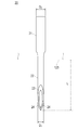
図1は、本発明の第1実施形態に係る薬液注入装置を示す図であって、(A)は概略断面図、(B)はキャップを外した状態の底面図である。図2は、図1に示される針の概略拡大図である。 1A and 1B are diagrams showing a chemical liquid injector according to a first embodiment of the present invention, in which FIG. 1A is a schematic cross-sectional view, and FIG. 1B is a bottom view with a cap removed. FIG. 2 is a schematic enlarged view of the needle shown in FIG.
図1に示されるように、本実施形態に係る薬液注入装置1は、本体10と針20とを有している。
As shown in FIG. 1, the
本体10は、薬液を収容可能な容器11と、容器11を保持するための保持体12と、容器11内の薬液を針20を介して経皮的に皮内へ注入するための駆動力を提供する薬液駆動手段としての板ばね13とを有する。
The
本明細書において、皮内とは、真皮層をいい、皮膚の表皮細胞層と真皮層の間の部位も含む。なお、本実施形態の薬液注入装置1は、薬液の皮内投与を意図したものであるが、結果的に皮下等の他の部位に薬液が注入される場合がある装置も含む。
In this specification, intradermal refers to the dermis layer, and includes the site between the epidermal cell layer and the dermis layer of the skin. In addition, although the chemical | medical
容器11は、略皿状を呈しており、板ばね13との間で内部空間111を形成している。また、容器11は、当該容器11の内部空間111内に薬液を充填するための充填口113を有する。充填口113には、チューブ41を介して、流路を開閉可能なバルブ42が取り付けられている。バルブ42には、薬液を供給するための図示しないシリンジ等の薬液供給装置を接続することができる。
The
保持体12は、先端側(図中下側)に開口する凹状部121を備える。また、凹状部121の開口端近傍の側方には、皮膚に当接可能な翼部122が設けられている。翼部122を設けることにより、薬液注入装置1は皮膚上に安定して支持され得る。ただし、本実施形態では、翼部を省略することも可能である。翼部122は、図1(B)に示されるように楕円板形状を呈しているが、略平板形状であれば任意の形状を採ることができる。
The holding
保持体12の凹状部121の内側底面123は、先端側に向かって凸形状に形成されることが好ましい。このような構成にすれば、内側底面123は後述するように針20が外方に突出する領域であるため、複数の針20が皮膚に均等に刺さりかつ刺さった状態を維持し易くなる。内側底面123の凸形状は、図1に示すような略円錐形状に限られるものではなく、たとえば球面形状の一部であってもよい。ただし、内側底面123は平面であってもよい。
The
本実施形態においては、容器11と保持体12とは、好ましくは、一体成形される。しかし、容器11と保持体12とを別部材として形成し、接着あるいは溶着等の手段によって、保持体12を容器11の端部に固着することも可能である。あるいは、容器11を、螺合もしくは嵌合によって、保持体12に着脱可能に接続する構成を採用することも可能である。
In the present embodiment, the
保持体12の皮膚に接触可能な端面には、粘着剤を含む粘着層30が形成されている。粘着層30は、凹状部121の内側底面123と、翼部122の端面124とに形成されるのが好ましいが、いずれか一方に形成されていてもよい。なお、粘着層30を省略する構成を採用することも可能である。凹状部121の内側底面123に粘着層30を形成することにより、針20の突出箇所近傍を皮膚にしっかりと粘着させることができ、また、翼部122の端面124に粘着層30を形成することにより、薬液注入装置1の保持体12を皮膚上にしっかりと固定することができる。これにより、針が皮膚から外れることをより確実に防止できる。粘着層30の外表面には、図示しない剥離シートが貼付されており、使用時に剥がされる。
An
粘着層30の粘着剤としては、一般的な粘着剤であれば使用可能であり、たとえば天然ゴム系粘着剤やアクリル系粘着剤が使用され得る。なお、粘着層には、たとえば皮膚を冷却するための物質等、粘着以外の目的の物質が含まれていてもよい。
As the pressure-sensitive adhesive of the pressure-
また、保持体12は、凹状部121内の空気を吸引するための吸引口125を有する。吸引口125には、チューブ51を介して、空気を吸引可能な図示しないシリンジ等の吸引装置を接続するためのコネクタ52が取り付けられている。吸引口125、チューブ51、コネクタ52および吸引装置は、凹状部121の内側底面123と皮膚とを相互に近接移動させて接触させるための接触手段として機能する。具体的には、吸引装置により吸引口125から空気を吸引することにより、凹状部121の内側底面123に皮膚を引き寄せて接触させることが可能となる。したがって、針を皮膚に確実に刺して針が皮膚から外れることを防止することができる。保持体12に接続されているチューブ51には、空気の逆流を防止するための逆止弁が設けられていてもよい。
Further, the holding
板ばね13の周縁部は、容器11の開口112の端部近傍に、揺動可能に取り付けられている。この板ばね13は、外方(図中上方)に凸形状を呈するように取り付けられる。板ばね13の外表面が使用者により押されることにより、板ばね13は、その中央部分が保持体12に向かって移動して内方(図中下方)に凸形状となり、容器11内の薬液を前方に押し出すことができる。つまり、凸形状に反って配置された板ばね13の凸面を押すことにより、板ばね13が初期と反対方向に凸形状となるときの力が利用される。なお、板ばね13と容器11との接続部は、薬液が漏れないようにシールされる。
The peripheral edge of the
内部空間111は、板ばね13が外方に凸形状を形成する場合に最大となり、所望の薬液量を貯留することができる。外方に凸形状の板ばね13が内方に凸形状と変形することにより、内部空間111はほぼゼロとなり、所定量の薬液が注入されたことになる。
The
板ばね13は、ばね鋼などの所定の弾性係数を有する板材で作られるが、たとえば樹脂板等の他の板材が使用されてもよい。容器11および保持体12は、ポリプロピレンやポリエチレンなどのプラスチックあるいはガラス等の材料を使用して、成形加工によって製造される。なお、容器11と保持体12は、透明なプラスチックが望ましい。
The
針20は、容器11内の内部空間111と連通しており、保持体12を貫通して凹状部121の内側底面123から外方へ突出している。針20は、中空形状を呈しており、複数本設けられる。図1(B)では、3本の針20が示されている。針の本数は、複数であれば薬液の投与量を効果的に増やすことができるため、2〜100本の範囲が好ましく、針穿刺の確実性や製造コストの観点を考慮すれば、2〜10本の範囲がより好ましい。
The
図2に示すように、針20の先端の外径D1は、0.1mm以上かつ0.25mm以下であり、針20の基端の外径D2は、先端の外径D1よりも大きく設定されている(かかる形状の針を「異径針」とも呼ぶ)。したがって、針の先端側を細くしたことにより穿刺痛が軽減されるだけでなく、基端側を太くしたことにより皮膚に穿刺するための針の強度を確保するとともに流路抵抗の上昇を防止することが可能である。また、針20が保持体12から先端側に脱落することを防止できる利点もある。
As shown in FIG. 2, the outer diameter D 1 of the tip of the
針20は、基端から凹状部121の内側底面123に対応する位置までの基部21と、凹状部121の内側底面123から突出し、生体内に穿刺可能な部分である穿刺部22とから構成される。なお、外径D2を有する太い部分の一部が凹状部121の内側底面123から外方に突出する構成であってもよい。
The
ここで、皮膚の角質層の厚さは一般に、個人、性別、年齢、身体の部位、生活環境によって異なっていて一定ではないが、人の腕においては、通常10〜30μmである。また、生きた表皮細胞層の厚さも種々の要因により一定ではないが、人の上腕部においては、通常30〜100μmである。また、真皮層の厚さも一定ではないが、通常1〜3mmである。 Here, the thickness of the stratum corneum of the skin generally varies depending on the individual, sex, age, body part, and living environment and is not constant, but is usually 10 to 30 μm in the human arm. Moreover, the thickness of the living epidermal cell layer is not constant due to various factors, but is usually 30 to 100 μm in the upper arm of a person. Also, the thickness of the dermis layer is not constant, but is usually 1 to 3 mm.
したがって、皮内投与を試みる場合、針20の皮膚内に穿刺される部分の長さは、好ましくは0.04〜2.5mm、より好ましくは0.5〜2.0mmの範囲内である。結果的に、針20のうち凹状部121の内側底面123から突出している部分、すなわち穿刺部22の全長L(皮膚に入らない部分も含めての全長)は、皮膚の柔軟性により穿刺部22の根元まで完全に押入されない場合があり得ることを考慮して、好ましくは0.1〜3mm、より好ましくは1〜2.5mmの範囲内である。
Therefore, when attempting intradermal administration, the length of the portion of the
また、針20の穿刺部22は、その先端側において、第1研削角で斜めにカットすることにより刃面が形成された主傾斜面23と、第2研削角で斜めにカットすることにより刃面が形成された一対の先端傾斜面24とを有している。これにより、針20の先端は皮膚に穿刺し易い点形状を呈する。
Further, the puncture portion 22 of the
図3に示すように、針は外径が先端から基端に向かって漸増していてもよい。図3に示す針20aは、図2に示す針20よりも強度が大きく、流路抵抗の変化も滑らかとなる利点がある。一方、図2に示す針20は、図3に示す針20aよりも製造が容易である。
As shown in FIG. 3, the outer diameter of the needle may gradually increase from the distal end toward the proximal end. The
図3に示す針20aもまた、基部21aと穿刺部22aとから構成されており、先端の外径D1、および穿刺部22の全長Lは、図2に示す針20と同様である。なお、針の全長にわたってではなく、針の長手方向の一部において、外径が先端から基端に向かって漸増していてもよい。
The
針20は、一般的には、ステンレス鋼を使用して、例えば、塑性加工によって製造される。但し、チタンなどの他の金属あるいはプラスチック等の材料から、針20を製造することも可能である。針20の本体10への固着は、例えば、インサート成形あるいは接着によって達成される。
The
また、薬液注入装置1には、針20の先端を保護するためのキャップ60が備えられていることが好ましい。これにより、針20の先端が誤って曲げられてしまうことを防止できるとともに、患者に恐怖感を与えないようにすることができる。キャップ60は、保持体12に対して、たとえば螺合もしくは嵌合等の方法により装着される。
Moreover, it is preferable that the
図1では、針20の先端は、翼部122の粘着層30が形成された端面124よりも突出しているが、端面124よりも基端側に位置されていてもよい。このようにすれば、針20を誤って皮膚に穿刺したり先端が誤って曲げられたりする事態をより防止できる。この場合、吸引口125から空気を吸引することによって、凹状部121の内側底面123に皮膚を引き寄せることにより、針20を皮膚に穿刺することが可能である。
In FIG. 1, the tip of the
このように構成された薬液注入装置1の使用方法について説明する。
The usage method of the
まず、キャップ60を薬液注入装置1から外す。針20の先端を上に向けた状態で、容器11に接続されたバルブ42を開け、バルブ42に接続されたシリンジ等の薬液供給装置を使用して、容器11内に薬液を充填する。薬液の充墳後、容器11内にある空気を抜く。次いで、バルブ42を閉じる。
First, the
そして、薬液注入装置1を皮膚の注射部位に、翼部122の端面124に形成された粘着層30によって接着させる。保持体12が皮膚にしっかりと接着されたことを確認した後、保持体12の吸引口125に接続されたチューブ51を介して凹状部121内の空気を吸引する。こうして凹状部121内に負圧が発生することにより、凹状部121の内側底面123に皮膚が引き寄せられ、針20が穿刺部22の根元近傍まで皮膚に刺さる。このとき、凹状部121の内側底面123に形成された粘着層30に皮膚が接着される。したがって、針20が皮膚から外れることを確実に防止できる。保持体12の凹状部121の内側底面123に皮膚が接着されていたら、板ばね13の外表面を押して容器11内の薬液を皮内に注入する。
Then, the
薬液注入装置1で使用される薬液は、薬剤を含有する溶液、ゲルまたは懸濁液である。使用可能な薬剤は、経皮的な投与に適さない薬剤以外であるならば、実質的に制限されない。
The drug solution used in the
主な薬剤としては、たとえば、抗菌薬、抗ウイルス薬、ワクチン、抗腫瘍薬、免疫抑制薬、ステロイド薬、抗炎症薬、抗リウマチ薬、関節炎治療薬、抗ヒスタミン薬、抗アレルギー薬、糖尿病治療薬、ホルモン剤、骨・カルシウム代謝薬、ビタミン、血液製剤、造血薬、抗血栓薬、抗高脂血症薬、抗不整脈薬、血管拡張薬、プロスタグランジン、カルシウム拮抗薬、ACE阻害薬、βブロッカー、降圧薬、利尿薬、キサンチン誘導体、βアゴニスト、抗喘息薬、鎮咳薬、去痰薬、抗コリン薬、止寫薬、健胃消化薬、抗潰瘍薬、下剤、睡眠薬、鎮静薬、解熱剤、かぜ薬、抗てんかん薬、抗精神病薬、抗うつ薬、抗不安薬、中枢神経刺激薬、副交感神経作用薬、交感神経作用薬、制吐剤、中枢興奮薬、抗パーキンソン病薬、筋弛緩薬、鎮痙薬、麻酔薬、鎮痒薬、抗片頭痛薬、診断薬、オリゴヌクレオチド、遺伝子薬などが挙げられる。ただし、薬剤は、好ましくは、経口投与で効果を表さないかあるいは減弱してしまうタンパク、ぺプチド、多糖類、オリゴヌクレオチド、DNA等であり、具体的には、インスリン、成長ホルモン、インターフェロン、カルシトニン等の高分子量医薬品である。 Major drugs include, for example, antibacterial drugs, antiviral drugs, vaccines, antitumor drugs, immunosuppressive drugs, steroid drugs, anti-inflammatory drugs, antirheumatic drugs, arthritis drugs, antihistamine drugs, antiallergic drugs, diabetes treatment Drugs, hormones, bone / calcium metabolizers, vitamins, blood products, hematopoietics, antithrombotics, antihyperlipidemics, antiarrhythmics, vasodilators, prostaglandins, calcium antagonists, ACE inhibitors, β-blocker, antihypertensive, diuretic, xanthine derivative, β agonist, anti-asthma, antitussive, expectorant, anticholinergic, antidiarrheal, gastrointestinal, antiulcer, laxative, hypnotic, sedative, antipyretic , Cold medicine, antiepileptic drug, antipsychotic drug, antidepressant drug, anxiolytic drug, central nervous stimulant, parasympathomimetic drug, sympathomimetic drug, antiemetic, central stimulant drug, antiparkinsonian drug, muscle relaxant , Antispasmodics, anesthesia Drugs, antipruritics, anti-migraine drugs, diagnostic drugs, oligonucleotides, gene drugs and the like. However, the drug is preferably a protein, peptide, polysaccharide, oligonucleotide, DNA, or the like that does not show an effect or is attenuated by oral administration, specifically, insulin, growth hormone, interferon, It is a high molecular weight pharmaceutical such as calcitonin.
このように第1実施形態の薬液注入装置によれば、複数の針を使用することにより針を細くして痛みを軽減しつつ皮膚に穿刺できるとともに、針が皮膚から外れることを防止することができ、しかも薬液の注入作用が自動的に行われる。したがって、十分かつ正確な量のたとえば経口投与の難しい高分子医薬品などの薬液を、経皮的に皮内へ確実かつ容易に注入することができる。 Thus, according to the chemical injection device of the first embodiment, by using a plurality of needles, it is possible to puncture the skin while reducing the pain by reducing the needles and to prevent the needles from coming off the skin. In addition, the injection of the chemical solution is automatically performed. Therefore, a sufficient and accurate amount of a drug solution such as a polymer drug difficult to be administered orally can be reliably and easily injected into the skin percutaneously.
図4は、本発明の第2実施形態に係る薬液注入装置を示す図であって、(A)は概略断面図、(B)はキャップを外した状態の底面図である。以下、第1実施形態と相違する点を中心に説明する。なお、第1実施形態と共通する機能を有する部材には同一の符号を用いる。 4A and 4B are diagrams showing a chemical liquid injector according to a second embodiment of the present invention, in which FIG. 4A is a schematic cross-sectional view, and FIG. 4B is a bottom view with a cap removed. Hereinafter, a description will be given focusing on differences from the first embodiment. In addition, the same code | symbol is used for the member which has a function which is common in 1st Embodiment.
第2実施形態に係る薬液注入装置1aは、容器11内の薬液を針20を介して経皮的に皮内へ注入するための駆動力を提供する薬液駆動手段が、第1実施形態と相違している。
The chemical
具体的には、薬液駆動手段は、容器11内に挿入されるガスケット131を押圧するためのコイルばね132を有する。
Specifically, the chemical liquid drive means has a
図4に示すように、容器11の基端側の開口112には、カバー部材134がたとえば螺合により取り付けられる。コイルばね132は、ガスケット131とカバー部材134との間に圧縮状態で介装される。
As shown in FIG. 4, a
また、容器11の中心軸に沿ってプランジャー133が配置されている。プランジャー133の先端部は、ガスケット131に固着される。一方、プランジャー133の基端部は、後述するラッチ部材135の先端部が内方に入り込んで係合する係合面を有している。ラッチ部材135は所定の弾性を有しており、外力により先端部が外方に変形可能である。したがって、スタートボタン136を押すと、ラッチ部材135の先端部を外方に移動させることができ、プランジャー133の基端部の係合面からラッチ部材135の先端部を離脱させることができる。なお、ガスケット131およびプランジャー133の移動を制御するためのラッチ部材135を用いた上記構成は、一例であり適宜変更可能である。ガスケット131は、ブチルゴム、シリコンゴム、あるいはエラストマー等の材料を使用する成形加工によって製造される。プランジャー133に使用される材料としては、例えば、プラスチック、ガラス、金属等が挙げられる。
A
このように構成された薬液注入装置1aを使用する場合、まず、キャップ60を薬液注入装置1から外す。針20の先端を上に向けた状態で、容器11に接続されたバルブ42を開け、バルブ42に接続されたシリンジ等の薬液供給装置を使用して、容器11内に薬液を充填する。薬液の充墳後、容器11内にある空気を抜く。次いで、バルブ42を閉じる。
When using the
そして、薬液注入装置1を皮膚の注射部位に、翼部122の端面124に形成された粘着層30によって接着させる。保持体12が皮膚にしっかりと接着されたことを確認した後、保持体12の吸引口125に接続されたチューブ51を介して凹状部121内の空気を吸引する。こうして凹状部121内に負圧が発生することにより、凹状部121の内側底面123に皮膚が引き寄せられ、針20が穿刺部22の根元近傍まで皮膚に刺さる。このとき、凹状部121の内側底面123に形成された粘着層30に皮膚が接着される。したがって、針20が皮膚から外れることを確実に防止できる。保持体12の凹状部121の内側底面123に皮膚が接着されていたら、薬液注入装置1の上部にあるスタートボタン136を押すことにより、コイルばね132の弾発力が解放されガスケット131が前方に押圧されて、容器11内の薬液を皮内に注入する。
Then, the
このように第2実施形態の薬液注入装置によっても、上記の第1実施形態と同様の効果を得ることが可能である。 Thus, also by the chemical | medical solution injection apparatus of 2nd Embodiment, it is possible to acquire the effect similar to said 1st Embodiment.
図5は、本発明の第3実施形態に係る薬液注入装置を示す図であって、(A)は概略断面図、(B)はキャップを外した状態の底面図である。以下、第1実施形態と相違する点を中心に説明する。なお、第1実施形態と共通する機能を有する部材には同一の符号を用いる。 5A and 5B are diagrams showing a chemical liquid injector according to a third embodiment of the present invention, in which FIG. 5A is a schematic cross-sectional view, and FIG. 5B is a bottom view with a cap removed. Hereinafter, a description will be given focusing on differences from the first embodiment. In addition, the same code | symbol is used for the member which has a function which is common in 1st Embodiment.
第3実施形態に係る薬液注入装置1bは、薬液を収容可能な弾性材料からなるバルーン11aと、バルーン11a内に連通する通路114を備えた接続部11bとを有する点で、第1実施形態と相違している。
The chemical
バルーン11aは、ゴム等の伸縮可能な弾性材料から作られており、通常時には萎んだ状態であり、薬剤を充填することにより図5(A)に示すように膨張する。接続部11bには、三方活栓115が設けられている。この三方活栓115により、バルーン11aへの通路、針20への通路、およびコネクタ116への通路の連通状態の切り替えが可能となる。コネクタ116には、薬液を供給するための図示しないシリンジ等の薬液供給装置を接続することができる。保持体12には、接続部11bの通路114と針20との間を繋ぐ分配通路128が形成されている。
The
このように構成された薬液注入装置1bを使用する場合、三方活栓115のコネクタ116に薬液を供給するためのシリンジを装着する。この後、三方活栓115のバルブを回して薬液の供給口を針20に連通させ、薬液を針20の先端まで満たす。次いで、三方活栓115のバルブを回して薬液の供給口をバルーン11aに連通させ、バルーン11a内に薬液を充填する。薬液の充墳後、バルブを閉じる。
When using the
そして、薬液注入装置1を皮膚の注射部位に、翼部122の端面124に形成された粘着層30によって接着させる。保持体12が皮膚にしっかりと接着されたことを確認した後、保持体12の吸引口125に接続されたチューブ51を介して凹状部121内の空気を吸引する。こうして凹状部121内に負圧が発生することにより、凹状部121の内側底面123に皮膚が引き寄せられ、針20が穿刺部22の根元近傍まで皮膚に刺さる。このとき、凹状部121の内側底面123に形成された粘着層30に皮膚が接着される。したがって、針20が皮膚から外れることを確実に防止できる。保持体12の凹状部121の内側底面123に皮膚が接着されていたら、三方活栓115のバルブを回してバルーン11aと針20を連通させることによって、バルーン11a自身の弾性力により、バルーン11a内の薬液を皮内に注入する。つまり、薬液が充填されて膨張したバルーン11aが縮むときの力が利用される。
Then, the
このように第3実施形態の薬液注入装置によっても、上記の第1実施形態と同様の効果を得ることが可能である。 As described above, the same effect as that of the first embodiment can be obtained by the chemical liquid injector according to the third embodiment.
図6は、本発明の第4実施形態に係る薬液注入装置を示す図であって、(A)は概略断面図、(B)はキャップを外した状態の底面図である。以下、第1実施形態と相違する点を中心に説明する。なお、第1実施形態と共通する機能を有する部材には同一の符号を用いる。 6A and 6B are diagrams showing a chemical liquid injector according to a fourth embodiment of the present invention, in which FIG. 6A is a schematic cross-sectional view, and FIG. 6B is a bottom view with a cap removed. Hereinafter, a description will be given focusing on differences from the first embodiment. In addition, the same code | symbol is used for the member which has a function which is common in 1st Embodiment.
第4実施形態に係る薬液注入装置1cは、薬液を送出可能な電動ポンプ11cと、電動ポンプ11cに連通する通路114aを備えた接続部11dとを有する点で、第1実施形態と相違している。
The
電動ポンプ11cは、着脱可能な図示しないシリンジを有している。電動ポンプ11cのシリンジは、チューブ117を介して、接続部11dに設けられたコネクタ116aに接続可能である。保持体12には、接続部11dの通路114aと針20との間を繋ぐ分配通路128が形成されている。
The
このように構成された薬液注入装置1cを使用する場合、キャップ60を外し、コネクタ116aに、チューブ117を介して、薬液を充填してあるシリンジを接続する。この後、シリンジのプランジャーを押して薬液を送り、シリンジ内、チューブ117内、針20内の空気を抜く。次いで、シリンジを電動ポンプ11cの本体に装着する。
When using the
そして、薬液注入装置1を皮膚の注射部位に、翼部122の端面124に形成された粘着層30によって接着させる。保持体12が皮膚にしっかりと接着されたことを確認した後、保持体12の吸引口125に接続されたチューブ51を介して凹状部121内の空気を吸引する。こうして凹状部121内に負圧が発生することにより、凹状部121の内側底面123に皮膚が引き寄せられ、針20が穿刺部22の根元近傍まで皮膚に刺さる。このとき、凹状部121の内側底面123に形成された粘着層30に皮膚が接着される。したがって、針20が皮膚から外れることを確実に防止できる。保持体12の凹状部121の内側底面123に皮膚が接着されていたら、電動ポンプ11cを作動させることによって、シリンジ内の薬液を皮内に持続注入する。
Then, the
このように第4実施形態の薬液注入装置によっても、上記の第1実施形態と同様の効果を得ることが可能である。 Thus, also by the chemical | medical solution injection device of 4th Embodiment, it is possible to acquire the effect similar to said 1st Embodiment.
次に、薬液の皮内投与に関する実験を行ったので、以下に説明する。 Next, an experiment related to intradermal administration of a chemical solution was performed, which will be described below.
〈実験1〉
インスリンを皮内に投与したときの血中動態が、従来実施されている皮下投与と同等であるか否かを確認する実験を実施した。
<
An experiment was conducted to confirm whether the blood kinetics when insulin was administered intradermally was equivalent to the conventional subcutaneous administration.
(方法)
雄性ラット(Crj:Wister、11週齢)を使用した。麻酔下で頚動脈にカテ一テルを留置し、薬液投与部位を毛刈りした。一夜絶食させた後、実験に供した。ラットを2群に分け、無麻酔拘束下でインスリンを、一方の群のラットに皮下、他方の群のラットに皮内投与した。注射には29G針(外径0.33mm)の付いたインスリンの用シリンジ(マイジェクター;テルモ株式会社製)を使用した。インスリン(ヒューマリンR注;塩野義製薬製)の投与量は、0.5U/kgであり、投与容量が約20μlになるように生理食塩水で希釈して使用した。インスリンを投与した後、5分、15分、30分、1時問、2時問および4時間後に、頚動脈から血液を採取して、それぞれの血中インスリン量を酵素免疫測定法を用いたインスリン測定用のキット(グラザイムInsulin−EIA TEST;和光純薬工業株式会社製)で測定した。
(Method)
Male rats (Crj: Wister, 11 weeks old) were used. Under anesthesia, a catheter was placed in the carotid artery and the drug solution administration site was shaved. After fasting overnight, it was used for the experiment. The rats were divided into two groups, and insulin was administered subcutaneously to one group of rats and intradermally to the other group of rats under unanesthetized restraint. A syringe for insulin (Myjector; manufactured by Terumo Corporation) with a 29G needle (outer diameter 0.33 mm) was used for injection. The dose of insulin (Humarin R injection; manufactured by Shionogi & Co., Ltd.) was 0.5 U / kg, and was used after diluting with physiological saline so that the dose volume was about 20 μl. After administration of insulin, blood was collected from the
(結果)
実験1の結果を図7に示す。図示のように、インスリン0.5U/kgを皮内投与すると、5分〜15分の間で血中インスリン濃度が最大になり、1時間持続する血中動態が得られた(図7中の破線)。これは、皮下注射したときの結果(図7中の実線)とほぼ同じであり、皮内投与しても皮下投与と同様の薬効を得ることができることがわかった。なお、図中の点は平均値、点から延びる縦線の長さは標準偏差を示す。
(result)
The result of
〈実験2〉
次に、1本あるいは3本の針で、どの程度の容量を皮内投与できるかを検討した。
<
Next, it was examined how much volume could be administered intradermally with one or three needles.
(方法)
約10kgのブタを使用した。麻酔下で横腹を毛刈りし、チューブの先に取り付けた異径針を、ブタ横腹に垂直に深さ1.0mm〜1.2mmになるように穿刺した。穿刺部位を固定した後、チューブの他端を生理食塩水を含む10mlのシリンジに接続し、シリンジポンプ(STC−531;テルモ株式会社製)を用いてブタの皮内に生理食塩水を持続注入した。単位時間当たりの投与量は、1時問当たり0.05ml、0.15ml、0.5ml、5mlの4通りとした。チューブには側枝を設け、この側枝にコモカーディオ連続心拍出量モニター(CO−203;テルモ株式会社製)を接続して、注入圧を連続的に測定できるようにした。皮膚からの漏れは、生理食塩水に青インクを混合することにより肉眼で判断した。また、ポンプの注入圧が安定せずに異常に上昇した場合は、その時点で実験を終了した。観察時間は、1本の針を用いた場合は1時間、3本の針を用いた場合は30分とした。本実験には、先端の外径が0.18mm(内径0.08mm)、チューブ側(基端)の外径が0.35mm(内径0.25mm)の全長12mmのステンレス製の異径針を用いた。また、針の先端には、第1研削角で斜めにカットすることにより刃面が形成された主傾斜面と、第2研削角で斜めにカットすることにより刃面が形成された一対の先端傾斜面とを設けた。
(Method)
About 10 kg pigs were used. Under anesthesia, the flank was shaved, and a different diameter needle attached to the tip of the tube was punctured to a depth of 1.0 mm to 1.2 mm perpendicular to the porcine flank. After fixing the puncture site, the other end of the tube is connected to a 10 ml syringe containing physiological saline, and physiological saline is continuously injected into the skin of the pig using a syringe pump (STC-531; manufactured by Terumo Corporation). did. There were four doses per unit time: 0.05 ml, 0.15 ml, 0.5 ml, and 5 ml per hour. The tube was provided with a side branch, and a comocardio continuous cardiac output monitor (CO-203; manufactured by Terumo Corporation) was connected to the side branch so that the injection pressure could be continuously measured. Leakage from the skin was judged with the naked eye by mixing blue ink into physiological saline. In addition, when the pump injection pressure was not stabilized and increased abnormally, the experiment was terminated at that time. The observation time was 1 hour when one needle was used and 30 minutes when three needles were used. In this experiment, a stainless steel different diameter needle having a total length of 12 mm and an outer diameter of the distal end of 0.18 mm (inner diameter 0.08 mm) and an outer diameter of the tube side (base end) of 0.35 mm (inner diameter 0.25 mm) was used. Using. In addition, at the tip of the needle, a main inclined surface having a blade surface formed by cutting obliquely at the first grinding angle and a pair of tips having a blade surface formed by cutting obliquely at the second grinding angle An inclined surface was provided.
(結果)
実験2の結果を図8に示す。図示のように、1本の針で投与量が1時間当たり0.15ml以下である場合、比較的安定的に生理食塩水を投与することができた。しかし、0.5ml/hrの投与量では、注入圧が上昇し、1時間後には皮膚も若干膨らんでいた。さらに5ml/hrの投与量では、0.1〜0.2ml注入後、投与不能になった。5ml/hrの実験結果が示すように、1本の単回投与ならば0.1〜0.2ml程度は皮内投与可能であることがわかった。さらに、3本の針による実験結果が示すように、針の本数を増やせば投与量も増やせる可能性のあることもわかった。
(result)
The result of
上記実験1および2の結果から、本発明の薬液注入装置を使用して薬液を経皮的に皮内へ注入することにより、所望の薬効を得ることが可能となることがわかる。
From the results of the
なお、本発明は、上述した実施形態に限定されるものではなく、特許請求の範囲内で種々改変することができる。 The present invention is not limited to the above-described embodiments, and various modifications can be made within the scope of the claims.
上述した実施形態では、保持体の吸引口から空気を吸引することにより、凹状部の内側底面に皮膚を引き寄せて接触させる場合について説明したが、本発明の接触手段はかかる場合に限定されるものではない。たとえば、保持体の翼部は皮膚面と平行に内側(半径方向内方)に移動可能な少なくとも一対の翼片を有し、翼片が皮膚に当接された状態で当該翼片を内側にずらすことにより、皮膚を当該翼片で挟んで持ち上げ凹状部の内側底面に引き寄せて接触させる構成が採用されてもよい。ここで、翼片は、側壁を介して保持体の基部に接続されており、これらは、たとえば樹脂により一体成形されることによって、各接続部分においてヒンジ結合される。また、翼部は皮膚面と平行に外側(半径方向外方)に移動可能な少なくとも一対の翼片を有し、翼片が皮膚に当接された状態で当該翼片を外側にずらすことにより、凹状部の側壁がつぶれて略平坦になって凹状部の内側底面に皮膚を接触させる構成が採用されてもよい。 In the above-described embodiment, the case where the skin is attracted and brought into contact with the inner bottom surface of the concave portion by sucking air from the suction port of the holding body has been described, but the contact means of the present invention is limited to such a case. is not. For example, the wing portion of the holding body has at least a pair of wing pieces that can move inward (radially inward) parallel to the skin surface, and the wing pieces are inward with the wing pieces in contact with the skin. A configuration may be adopted in which the skin is sandwiched between the wing pieces and is lifted and brought into contact with the inner bottom surface by shifting. Here, the blade piece is connected to the base portion of the holding body via the side wall, and these are hinge-coupled at each connection portion by being integrally formed with resin, for example. The wing portion has at least a pair of wing pieces that can move outward (radially outward) in parallel to the skin surface, and the wing pieces are moved outward while the wing pieces are in contact with the skin. A configuration may be employed in which the side wall of the concave portion is crushed and becomes substantially flat so that the skin is brought into contact with the inner bottom surface of the concave portion.
1、1a、1b、1c 薬液注入装置、
10 本体、
11 容器、
11a バルーン、
11b、11d 接続部、
11c 電動ポンプ
111 内部空間、
113 充填口、
12 保持体、
121 凹状部、
122 翼部、
123 内側底面、
125 吸引口、
131 ガスケット、
132 コイルばね、
20、20a 針、
21、21a 基部、
22、22a 穿刺部、
30 粘着層、
60 キャップ、
D1、D2 針の外径、
L 穿刺部の全長。
1, 1a, 1b, 1c chemical injection device,
10 body,
11 containers,
11a balloon,
11b, 11d connection part,
11c Electric pump 111 interior space,
113 filling port,
12 holder,
121 concave part,
122 wings,
123 Inside bottom,
125 suction port,
131 gasket,
132 coil spring,
20, 20a needle,
21, 21a base,
22, 22a Puncture part,
30 adhesive layer,
60 caps,
D 1 , outer diameter of D 2 needle,
L Total length of puncture site.
Claims (10)
前記容器を保持するための保持体と、
前記容器内と連通され前記保持体を貫通して当該保持体から外方へ突出する複数の中空の針と、
前記容器内の薬液を前記針を介して経皮的に皮内へ注入するための駆動力を提供する薬液駆動手段とを有し、
前記薬液駆動手段は、前記容器内の薬液を押圧するための板ばねを有することを特徴とする薬液注入装置。 A container that can contain a chemical solution;
A holding body for holding the container;
A plurality of hollow needles communicating with the inside of the container and penetrating through the holding body and projecting outward from the holding body;
A drug solution driving means for providing a driving force for transdermally injecting the drug solution in the container into the skin through the needle,
The chemical solution injection device according to claim 1, wherein the chemical solution driving means includes a leaf spring for pressing the chemical solution in the container.
前記容器を保持するための保持体と、
前記容器内と連通され前記保持体を貫通して当該保持体から外方へ突出する複数の中空の針と、
前記容器内の薬液を前記針を介して経皮的に皮内へ注入するための駆動力を提供する薬液駆動手段とを有し、
前記薬液駆動手段は、前記容器内に挿入されるガスケットを押圧するためのコイルばねを有することを特徴とする薬液注入装置。 A container that can contain a chemical solution;
A holding body for holding the container;
A plurality of hollow needles communicating with the inside of the container and penetrating through the holding body and projecting outward from the holding body;
A drug solution driving means for providing a driving force for transdermally injecting the drug solution in the container into the skin through the needle,
The chemical liquid injector is characterized in that the chemical liquid drive means has a coil spring for pressing a gasket inserted into the container.
前記バルーン内と連通する通路を備えた接続部と、
前記接続部を保持するための保持体と、
前記通路と連通され前記保持体を貫通して当該保持体から外方へ突出する複数の中空の針と、
を有することを特徴とする薬液を経皮的に皮内へ注入するための薬液注入装置。 A balloon made of an elastic material capable of containing a chemical solution;
A connecting portion having a passage communicating with the inside of the balloon;
A holding body for holding the connecting portion;
A plurality of hollow needles communicating with the passage and penetrating through the holding body and projecting outward from the holding body;
A drug solution injection device for transcutaneously injecting a drug solution into the skin.
前記電動ポンプと連通する通路を備えた接続部と、
前記接続部を保持するための保持体と、
前記通路と連通され前記保持体を貫通して当該保持体から外方へ突出する複数の中空の針と、
を有することを特徴とする薬液を経皮的に皮内へ注入するための薬液注入装置。 An electric pump capable of delivering chemicals;
A connecting portion having a passage communicating with the electric pump;
A holding body for holding the connecting portion;
A plurality of hollow needles communicating with the passage and penetrating through the holding body and projecting outward from the holding body;
A drug solution injection device for transcutaneously injecting a drug solution into the skin.
前記針は、前記凹状部の内側底面から外方へ突出しており、
前記吸引口から空気を吸引することにより、前記凹状部の内側底面に皮膚を引き寄せて接触させることを特徴とする請求項1〜4のいずれか1つに記載の薬液注入装置。 The holding body has a concave portion that opens to the distal end side, and a suction port for sucking air in the concave portion,
The needle protrudes outward from the inner bottom surface of the concave portion,
The chemical injection device according to any one of claims 1 to 4, wherein the skin is attracted and brought into contact with the inner bottom surface of the concave portion by sucking air from the suction port.
前記針の基端の外径は、先端の外径よりも大きいことを特徴とする請求項1〜6のいずれか1つに記載の薬液注入装置。 The outer diameter of the tip of the needle is 0.1 mm or more and 0.25 mm or less,
The outer diameter of the proximal end of the needle is larger than the outer diameter of the distal end, and the medicinal solution injection device according to any one of claims 1 to 6.
前記穿刺部の全長は、1mm以上かつ2.5mm以下であることを特徴とする請求項1〜8のいずれか1つに記載の薬液注入装置。 The needle comprises a base from a base end to a position corresponding to the end face of the holding body, and a puncture part that protrudes from the end face of the holding body and is a part that can be punctured into a living body,
The total length of the puncture unit is 1 mm or more and 2.5 mm or less, The drug solution injection device according to any one of claims 1 to 8.
Priority Applications (1)
| Application Number | Priority Date | Filing Date | Title |
|---|---|---|---|
| JP2003326022A JP2005087520A (en) | 2003-09-18 | 2003-09-18 | Liquid medicine injector |
Applications Claiming Priority (1)
| Application Number | Priority Date | Filing Date | Title |
|---|---|---|---|
| JP2003326022A JP2005087520A (en) | 2003-09-18 | 2003-09-18 | Liquid medicine injector |
Publications (2)
| Publication Number | Publication Date |
|---|---|
| JP2005087520A true JP2005087520A (en) | 2005-04-07 |
| JP2005087520A5 JP2005087520A5 (en) | 2006-10-19 |
Family
ID=34456319
Family Applications (1)
| Application Number | Title | Priority Date | Filing Date |
|---|---|---|---|
| JP2003326022A Pending JP2005087520A (en) | 2003-09-18 | 2003-09-18 | Liquid medicine injector |
Country Status (1)
| Country | Link |
|---|---|
| JP (1) | JP2005087520A (en) |
Cited By (22)
| Publication number | Priority date | Publication date | Assignee | Title |
|---|---|---|---|---|
| JP2009093240A (en) * | 2007-10-04 | 2009-04-30 | Hitachi Ltd | Method for binding rf tag to individual identification number |
| US7740600B2 (en) | 2002-08-02 | 2010-06-22 | Candela Corporation | Apparatus and method for inhibiting pain signals transmitted during a skin related medical treatment |
| US7740651B2 (en) | 2007-09-28 | 2010-06-22 | Candela Corporation | Vacuum assisted treatment of the skin |
| US7762965B2 (en) | 2001-12-10 | 2010-07-27 | Candela Corporation | Method and apparatus for vacuum-assisted light-based treatments of the skin |
| US7762964B2 (en) | 2001-12-10 | 2010-07-27 | Candela Corporation | Method and apparatus for improving safety during exposure to a monochromatic light source |
| US7771374B2 (en) | 2001-12-10 | 2010-08-10 | Candela Corporation | Method and apparatus for vacuum-assisted light-based treatments of the skin |
| US7935139B2 (en) | 2001-12-10 | 2011-05-03 | Candela Corporation | Eye safe dermatological phototherapy |
| US8123699B2 (en) | 2007-09-04 | 2012-02-28 | Lyon Thomas R | Method and apparatus for aspiration |
| KR101305539B1 (en) | 2012-02-16 | 2013-09-06 | (주)메가메디칼 | gun for injection of a liquid medicine |
| CN104587562A (en) * | 2014-12-26 | 2015-05-06 | 杨力 | Angina pectoris self-rescue needle |
| JP2015091453A (en) * | 2010-02-01 | 2015-05-14 | ベクトン・ディキンソン・アンド・カンパニーBecton, Dickinson And Company | Low dose prefilled drug delivery device |
| WO2015105162A1 (en) * | 2014-01-08 | 2015-07-16 | ニプロ株式会社 | Hollow needle and production method for hollow needle |
| JP2017533774A (en) * | 2014-11-14 | 2017-11-16 | サイトレリス バイオシステムズ,インコーポレーテッド | Device and method for skin ablation |
| WO2018056403A1 (en) * | 2016-09-23 | 2018-03-29 | テルモ株式会社 | Medical instrument and administration method |
| AU2016220141B2 (en) * | 2015-02-17 | 2018-07-12 | Amgen Inc. | Drug delivery device with vacuum assisted securement and/or feedback |
| US10390753B2 (en) | 2014-10-21 | 2019-08-27 | Alltest Gmbh | Blister strip |
| US10595760B2 (en) | 2015-05-05 | 2020-03-24 | University Of Massachusetts | Compliant syringe system, a method of making, and of using the same |
| US10953143B2 (en) | 2013-12-19 | 2021-03-23 | Cytrellis Biosystems, Inc. | Methods and devices for manipulating subdermal fat |
| KR102247709B1 (en) * | 2020-08-06 | 2021-05-07 | 이민우 | Injection Apparatus for Injection Liquid |
| US11166743B2 (en) | 2016-03-29 | 2021-11-09 | Cytrellis Biosystems, Inc. | Devices and methods for cosmetic skin resurfacing |
| US11464954B2 (en) | 2016-09-21 | 2022-10-11 | Cytrellis Biosystems, Inc. | Devices and methods for cosmetic skin resurfacing |
| US11534344B2 (en) | 2013-02-20 | 2022-12-27 | Cytrellis Biosystems, Inc. | Methods and devices for skin tightening |
Citations (4)
| Publication number | Priority date | Publication date | Assignee | Title |
|---|---|---|---|---|
| JPS5695058A (en) * | 1979-12-10 | 1981-08-01 | Toyo Jozo Kk | Microosyringe |
| JPH08508901A (en) * | 1993-04-08 | 1996-09-24 | イーラン・メディカル・テクノロジーズ・リミテッド | Intradermal injection device |
| JPH09504974A (en) * | 1993-11-18 | 1997-05-20 | イーラン・メディカル・テクノロジーズ・リミテッド | Intradermal drug feeder |
| JP2002291884A (en) * | 2001-01-25 | 2002-10-08 | Terumo Corp | Liquid injection needle and liquid injecting unit |
-
2003
- 2003-09-18 JP JP2003326022A patent/JP2005087520A/en active Pending
Patent Citations (4)
| Publication number | Priority date | Publication date | Assignee | Title |
|---|---|---|---|---|
| JPS5695058A (en) * | 1979-12-10 | 1981-08-01 | Toyo Jozo Kk | Microosyringe |
| JPH08508901A (en) * | 1993-04-08 | 1996-09-24 | イーラン・メディカル・テクノロジーズ・リミテッド | Intradermal injection device |
| JPH09504974A (en) * | 1993-11-18 | 1997-05-20 | イーラン・メディカル・テクノロジーズ・リミテッド | Intradermal drug feeder |
| JP2002291884A (en) * | 2001-01-25 | 2002-10-08 | Terumo Corp | Liquid injection needle and liquid injecting unit |
Cited By (33)
| Publication number | Priority date | Publication date | Assignee | Title |
|---|---|---|---|---|
| US7935139B2 (en) | 2001-12-10 | 2011-05-03 | Candela Corporation | Eye safe dermatological phototherapy |
| US7762965B2 (en) | 2001-12-10 | 2010-07-27 | Candela Corporation | Method and apparatus for vacuum-assisted light-based treatments of the skin |
| US7762964B2 (en) | 2001-12-10 | 2010-07-27 | Candela Corporation | Method and apparatus for improving safety during exposure to a monochromatic light source |
| US7771374B2 (en) | 2001-12-10 | 2010-08-10 | Candela Corporation | Method and apparatus for vacuum-assisted light-based treatments of the skin |
| US7740600B2 (en) | 2002-08-02 | 2010-06-22 | Candela Corporation | Apparatus and method for inhibiting pain signals transmitted during a skin related medical treatment |
| US8986220B2 (en) | 2007-09-04 | 2015-03-24 | Thomas R. Lyon | Spinal aspiration apparatus |
| US9078693B2 (en) | 2007-09-04 | 2015-07-14 | Thomas R. Lyon | Method and apparatus for aspiration |
| US8123699B2 (en) | 2007-09-04 | 2012-02-28 | Lyon Thomas R | Method and apparatus for aspiration |
| US7740651B2 (en) | 2007-09-28 | 2010-06-22 | Candela Corporation | Vacuum assisted treatment of the skin |
| JP2009093240A (en) * | 2007-10-04 | 2009-04-30 | Hitachi Ltd | Method for binding rf tag to individual identification number |
| US11738150B2 (en) | 2010-02-01 | 2023-08-29 | Becton, Dickinson And Company | Low dose prefilled drug delivery device and method |
| JP2015091453A (en) * | 2010-02-01 | 2015-05-14 | ベクトン・ディキンソン・アンド・カンパニーBecton, Dickinson And Company | Low dose prefilled drug delivery device |
| US9849247B2 (en) | 2010-02-01 | 2017-12-26 | Becton, Dickinson And Company | Low dose prefilled drug delivery device and method |
| US10898648B2 (en) | 2010-02-01 | 2021-01-26 | Becton, Dickinson And Company | Low dose prefilled drug delivery device and method |
| KR101305539B1 (en) | 2012-02-16 | 2013-09-06 | (주)메가메디칼 | gun for injection of a liquid medicine |
| US11534344B2 (en) | 2013-02-20 | 2022-12-27 | Cytrellis Biosystems, Inc. | Methods and devices for skin tightening |
| US10953143B2 (en) | 2013-12-19 | 2021-03-23 | Cytrellis Biosystems, Inc. | Methods and devices for manipulating subdermal fat |
| WO2015105162A1 (en) * | 2014-01-08 | 2015-07-16 | ニプロ株式会社 | Hollow needle and production method for hollow needle |
| JP2015147042A (en) * | 2014-01-08 | 2015-08-20 | ニプロ株式会社 | Hollow needle and method of manufacturing the same |
| US10390753B2 (en) | 2014-10-21 | 2019-08-27 | Alltest Gmbh | Blister strip |
| US11497434B2 (en) | 2014-10-21 | 2022-11-15 | Alltest Gmbh | Blister strip |
| US11324534B2 (en) | 2014-11-14 | 2022-05-10 | Cytrellis Biosystems, Inc. | Devices and methods for ablation of the skin |
| US11896261B2 (en) | 2014-11-14 | 2024-02-13 | Cytrellis Biosystems, Inc. | Devices and methods for ablation of the skin |
| JP2017533774A (en) * | 2014-11-14 | 2017-11-16 | サイトレリス バイオシステムズ,インコーポレーテッド | Device and method for skin ablation |
| CN104587562A (en) * | 2014-12-26 | 2015-05-06 | 杨力 | Angina pectoris self-rescue needle |
| AU2016220141B2 (en) * | 2015-02-17 | 2018-07-12 | Amgen Inc. | Drug delivery device with vacuum assisted securement and/or feedback |
| US11517663B2 (en) | 2015-02-17 | 2022-12-06 | Amgen Inc. | Drug delivery device with vacuum assisted securement and/or feedback |
| US10583245B2 (en) | 2015-02-17 | 2020-03-10 | Amgen Inc. | Drug delivery device with vacuum assisted securement and/or feedback |
| US10595760B2 (en) | 2015-05-05 | 2020-03-24 | University Of Massachusetts | Compliant syringe system, a method of making, and of using the same |
| US11166743B2 (en) | 2016-03-29 | 2021-11-09 | Cytrellis Biosystems, Inc. | Devices and methods for cosmetic skin resurfacing |
| US11464954B2 (en) | 2016-09-21 | 2022-10-11 | Cytrellis Biosystems, Inc. | Devices and methods for cosmetic skin resurfacing |
| WO2018056403A1 (en) * | 2016-09-23 | 2018-03-29 | テルモ株式会社 | Medical instrument and administration method |
| KR102247709B1 (en) * | 2020-08-06 | 2021-05-07 | 이민우 | Injection Apparatus for Injection Liquid |
Similar Documents
| Publication | Publication Date | Title |
|---|---|---|
| JP4409239B2 (en) | Chemical injection device | |
| JP2005087520A (en) | Liquid medicine injector | |
| EP1757240B1 (en) | Valved intradermal delivery device | |
| US8652095B2 (en) | Skin retention device for a medical jet injection kit | |
| US7998119B2 (en) | System and method for delivering fluid into flexible biological barrier | |
| JP5063358B2 (en) | Puncture device, administration device and puncture method | |
| US8007466B2 (en) | System and method for delivering fluid into flexible biological barrier | |
| CN100509072C (en) | Intradermal injection device | |
| JP4286897B2 (en) | Ampoule that can be used as a syringe, and syringe unit | |
| CN102369034A (en) | Syringe needle assembly and medicament injection device | |
| EP2531242B1 (en) | Dermal access device | |
| US20090247953A1 (en) | Microneedle adaptor for dosed drug delivery devices | |
| JP2004503342A (en) | Micro device and method for manufacturing the same | |
| CN102596294A (en) | Injection needle assembly and drug injection apparatus | |
| JP2012100783A (en) | Liquid medicine supply device | |
| US8876764B2 (en) | Intradermal pen adapter | |
| JP2005087521A (en) | Liquid medicine injector | |
| JP4153736B2 (en) | Needle | |
| US20150038911A1 (en) | Microneedle adapter for dosed drug delivery devices | |
| JP2011045565A (en) | Liquid medicine injector | |
| US20220273877A1 (en) | Medical Agent Dispensing Apparatuses, Systems, and Methods |
Legal Events
| Date | Code | Title | Description |
|---|---|---|---|
| A521 | Written amendment |
Free format text: JAPANESE INTERMEDIATE CODE: A523 Effective date: 20060906 |
|
| A621 | Written request for application examination |
Free format text: JAPANESE INTERMEDIATE CODE: A621 Effective date: 20060906 |
|
| A977 | Report on retrieval |
Free format text: JAPANESE INTERMEDIATE CODE: A971007 Effective date: 20090924 |
|
| A131 | Notification of reasons for refusal |
Free format text: JAPANESE INTERMEDIATE CODE: A131 Effective date: 20090929 |
|
| A521 | Written amendment |
Free format text: JAPANESE INTERMEDIATE CODE: A523 Effective date: 20091130 |
|
| A02 | Decision of refusal |
Free format text: JAPANESE INTERMEDIATE CODE: A02 Effective date: 20100413 |