JP2005077522A - Image processor and image processing method - Google Patents
Image processor and image processing method Download PDFInfo
- Publication number
- JP2005077522A JP2005077522A JP2003305273A JP2003305273A JP2005077522A JP 2005077522 A JP2005077522 A JP 2005077522A JP 2003305273 A JP2003305273 A JP 2003305273A JP 2003305273 A JP2003305273 A JP 2003305273A JP 2005077522 A JP2005077522 A JP 2005077522A
- Authority
- JP
- Japan
- Prior art keywords
- coefficient
- data
- sprite
- buffer
- image
- Prior art date
- Legal status (The legal status is an assumption and is not a legal conclusion. Google has not performed a legal analysis and makes no representation as to the accuracy of the status listed.)
- Pending
Links
Images


Classifications
-
- G—PHYSICS
- G09—EDUCATION; CRYPTOGRAPHY; DISPLAY; ADVERTISING; SEALS
- G09G—ARRANGEMENTS OR CIRCUITS FOR CONTROL OF INDICATING DEVICES USING STATIC MEANS TO PRESENT VARIABLE INFORMATION
- G09G5/00—Control arrangements or circuits for visual indicators common to cathode-ray tube indicators and other visual indicators
- G09G5/36—Control arrangements or circuits for visual indicators common to cathode-ray tube indicators and other visual indicators characterised by the display of a graphic pattern, e.g. using an all-points-addressable [APA] memory
- G09G5/39—Control of the bit-mapped memory
- G09G5/393—Arrangements for updating the contents of the bit-mapped memory
-
- G—PHYSICS
- G06—COMPUTING; CALCULATING OR COUNTING
- G06T—IMAGE DATA PROCESSING OR GENERATION, IN GENERAL
- G06T15/00—3D [Three Dimensional] image rendering
- G06T15/50—Lighting effects
- G06T15/503—Blending, e.g. for anti-aliasing
-
- G—PHYSICS
- G09—EDUCATION; CRYPTOGRAPHY; DISPLAY; ADVERTISING; SEALS
- G09G—ARRANGEMENTS OR CIRCUITS FOR CONTROL OF INDICATING DEVICES USING STATIC MEANS TO PRESENT VARIABLE INFORMATION
- G09G2360/00—Aspects of the architecture of display systems
- G09G2360/12—Frame memory handling
- G09G2360/126—The frame memory having additional data ports, not inclusive of standard details of the output serial port of a VRAM
Abstract
Description
本発明は、画像処理装置および画像処理方法に関する。 The present invention relates to an image processing apparatus and an image processing method.
従来、ビデオゲーム装置などに適用される画像表示装置では、スプライト表示方式が用いられている。ここで、スプライト表示方式とは、画面に表示されるキャラクタ毎に表示位置などの属性(スプライト属性)を持ち、そのスプライト属性に従いキャラクタを配置することで画面全体を構成する方式である。そして、表示位置などのスプライト属性を持ったキャラクタをスプライトという。ビデオゲーム装置などのように、インタラクティブに高速にキャラクタを動かす場合、スプライト表示方式では動かすキャラクタのスプライト属性を変更するだけで画面の書き換えをすることができる。 Conventionally, an image display device applied to a video game device or the like uses a sprite display method. Here, the sprite display method is a method of configuring the entire screen by having an attribute (sprite attribute) such as a display position for each character displayed on the screen and arranging the characters according to the sprite attribute. A character having a sprite attribute such as a display position is called a sprite. When a character is moved interactively at a high speed as in a video game apparatus, the screen can be rewritten only by changing the sprite attribute of the character to be moved in the sprite display method.
また、従来の画像表示装置では、2つ以上の画像を係数(アルファ値又はα係数)を使って半透明合成するαブレンディング(アルファブレンド)機能を備えるものがある。このαブレンディング機能では、画像の全画素に共通のα係数を指定することもあるが、画像の各画素に対応させてα係数の情報を持たせてそれを利用することによって画素ごとの半透明合成を行うこともできる(例えば、特許文献1参照)。
しかしながら、特許文献1などに記載されている従来の画像処理装置では、αブレンディングを行うためには、複数のスプライトにおいて表示優先順位の低いスプライトから順番にフレームバッファに描画する必要がある。カラー演算を行う場合もあるが、基本的には、優先順位の高いスプライトは優先順位の低いスプライトの上に上書きされるからである。
However, in the conventional image processing apparatus described in
フレームバッファに表示優先順位の低いスプライトから順番に描画する場合は、全てのスプライトをフレームバッファに描画する必要がある。ここで、描画性能は、単位時間に描画できるドット数で表されるが、従来の画像処理装置では、表示優先順位の低いスプライトから全てのスプライトを順番にフレームバッファに描画する必要があるため、描画性能の向上が阻害されているという問題点があった。 When drawing in order from the sprite having the lowest display priority in the frame buffer, it is necessary to draw all the sprites in the frame buffer. Here, the drawing performance is represented by the number of dots that can be drawn per unit time. However, in the conventional image processing apparatus, it is necessary to draw all the sprites in order from the sprite having the lowest display priority in the frame buffer. There was a problem that improvement in drawing performance was hindered.
本発明は、上記問題点を解決するためになされたものであり、表示優先順位の高いスプライトから描画することができ、かつ複数面についてのカラー演算を行うこともできる画像処理装置および画像処理方法を提供するものである。 The present invention has been made to solve the above-described problems, and is an image processing apparatus and an image processing method capable of drawing from a sprite having a high display priority and performing a color operation on a plurality of surfaces. Is to provide.
上記課題を解決するため、この発明は以下の構成を有する。
即ち、請求項1に記載された発明に係る画像処理装置は、表示手段に出力される表示画像データをビットマップ形式で保持するフレームバッファと、前記表示画像データの各画素に対応させて設定されている係数データであると共に、各画素位置の透過度情報を示す係数データであるα係数を格納するα係数バッファと、前記α係数を使って2つの画像を半透明合成する処理であるαブレンディングの実行時に、該2つの画像における表示優先度が低い方の画像である下位面に対するα係数を計算し、該α係数を前記α係数バッファに格納させるα係数計算モジュールと、前記2つの画像における表示優先度が高い方の画像である上位面又は前記下位面を前記フレームバッファに描画するときに、描画データ、描画済みデータ及び前記α係数バッファに格納されているデータを用いてαブレンディングを行うと共に、該上位面のスプライトを前記フレームバッファに描画した後に、該下位面のスプライトを該フレームバッファに描画するαブレンディングモジュールとを有することを特徴とする。
In order to solve the above problems, the present invention has the following configuration.
In other words, the image processing apparatus according to the first aspect of the present invention is set corresponding to each frame of the display buffer and a frame buffer that holds the display image data output to the display means in a bitmap format. An α coefficient buffer that stores α coefficient that is coefficient data indicating the transparency information of each pixel position, and α blending that is a process of translucently combining two images using the α coefficient An α coefficient calculation module that calculates an α coefficient for a lower surface that is an image having a lower display priority in the two images and stores the α coefficient in the α coefficient buffer; and When the upper surface or the lower surface, which is the image with the higher display priority, is drawn in the frame buffer, the drawing data, the drawn data, and the α coefficient buffer are drawn. And α blending using the data stored in the frame buffer, and after drawing the upper surface sprite in the frame buffer, the α blending module for drawing the lower surface sprite in the frame buffer. And
また、請求項2に記載された発明に係る画像処理装置は、表示手段に出力される表示画像データをビットマップ形式で保持するフレームバッファと、前記表示画像データの各画素に対応させて設定されている係数データであると共に、2つの画像を重ねてなる合成画像の各画素データを算出するピクセル演算に用いる係数データを格納する係数バッファと、前記ピクセル演算を算出するときに、前記2つの画像における表示優先度が低い方の画像である下位面に対する前記係数データを計算し、該係数データを前記係数バッファに格納させる係数計算モジュールと、前記2つの画像における表示優先度が高い方の画像である上位面又は前記下位面を前記フレームバッファに描画するときに、描画データ、描画済みデータ及び前記係数バッファに格納されているデータを用いて前記ピクセル演算を行うと共に、該上位面のスプライトを前記フレームバッファに描画した後に、該下位面のスプライトを該フレームバッファに描画するピクセル演算モジュールとを有することを特徴とする。
The image processing apparatus according to the invention described in
また、請求項3に記載された発明に係る画像処理方法は、表示画像の各画素に対応させて設定されている係数データであると共に、各画素位置の透過度情報を示す係数データであるα係数を格納するα係数バッファを用いて、前記表示画像をフレームバッファに一旦保持させて表示手段に表示させる画像処理方法であって、前記α係数を使って2つの画像を半透明合成する処理であるαブレンディング実行時は、該2つの画像における表示優先度が低い方の画像である下位面に対するα係数を計算し、該α係数を前記α係数バッファに格納し、前記2つの画像における表示優先度が高い方の画像である上位面又は前記下位面を前記フレームバッファに描画するときは、描画データ、描画済みデータ及び前記α係数バッファに格納されているデータを用いてαブレンディングを行うと共に、該上位面のスプライトを前記フレームバッファに描画した後に、該下位面のスプライトを該フレームバッファに描画することを特徴とする。 The image processing method according to the third aspect of the present invention is coefficient data set corresponding to each pixel of the display image and coefficient data indicating the transparency information of each pixel position. An image processing method for temporarily holding the display image in a frame buffer and displaying the display image on a display unit using an α coefficient buffer for storing coefficients, wherein the two images are translucently synthesized using the α coefficient. When a certain α blending is executed, an α coefficient is calculated for a lower surface which is an image having a lower display priority in the two images, the α coefficient is stored in the α coefficient buffer, and display priority in the two images is calculated. When drawing the upper surface or the lower surface, which is the higher image, in the frame buffer, the drawing data, the drawn data, and the data stored in the α coefficient buffer are And blending with each other, drawing the upper surface sprite in the frame buffer, and then drawing the lower surface sprite in the frame buffer.
また、請求項4に記載された発明に係る画像処理方法は、表示画像の各画素に対応させて設定されている係数データであると共に、2つの画像を重ねてなる合成画像の各画素データを算出するピクセル演算に用いる係数データを格納する係数バッファを用いて、前記表示画像をフレームバッファに一旦保持させて表示手段に表示させる画像処理方法であって、前記合成画像を算出するときに、前記2つの画像における表示優先度が低い方の画像である下位面に対する前記係数データを計算し、該係数データを前記係数バッファに格納し、前記2つの画像における表示優先度が高い方の画像である上位面又は前記下位面を前記フレームバッファに描画するときは、描画データ、描画済みデータ及び前記係数バッファに格納されているデータを用いて前記ピクセル演算を行うと共に、該上位面のスプライトを前記フレームバッファに描画した後に、該下位面のスプライトを該フレームバッファに描画することを特徴とする。
In addition, the image processing method according to the invention described in
本発明によれば、表示優先順位の高いスプライトから描画することができ、かつ複数面についてのカラー演算を行うこともできる。 According to the present invention, it is possible to draw from a sprite having a high display priority, and it is also possible to perform color calculation for a plurality of surfaces.
以下、図面を参照し、本発明の実施形態について説明する。
(第1実施形態)
図1は、本発明の実施形態に係る画像処理装置の構成例を示すブロック図である。本発明の実施形態に係る画像処理装置20は、画像表示装置1の構成要素となる。画像表示装置1は、CGメモリ11と、CPU12と、モニタ13と、本発明の実施形態に係る画像処理装置20とで構成されている。CPU12は、画像処理装置20の動作を制御し、CGメモリ11に格納されているキャラクタデータを用いて、モニタ13に所望の画面を表示させる。モニタ13は、LCDパネル又はCRTモニタなどの表示手段である。
Hereinafter, embodiments of the present invention will be described with reference to the drawings.
(First embodiment)
FIG. 1 is a block diagram illustrating a configuration example of an image processing apparatus according to an embodiment of the present invention. The
画像処理装置20は、CGメモリインターフェース21、リアルタイムデコーダ22、スプライトバッファ23、レンダリングプロセッサ24、フレームバッファ25、フレームデータ制御回路26、D/Aコンバータ27、スプライト・プレーン・ジェネレータ28、CPUインターフェース29、DMA制御回路30、カラーパレット31、汎用データテーブル32、レジスタ33、モニタ制御回路34及びクロック生成回路35で構成されている。
The
まず、画像処理装置20の主要概略動作について説明する。画像処理装置20は、CPU12の指示(汎用データテーブル32内のスプライト属性テーブルへのスプライト属性データの書き込み)にしたがって動作する。すなわち、画像処理装置20は、1フレーム期間内において、汎用データテーブル32内のスプライト属性テーブルからスプライト属性データを順次読み出し、そのスプライト属性データに基づき、CGメモリ11に記憶されたキャラクタを使用してスプライトを生成し、フレームバッファ25に描画する。なお、詳細は後述するが、本発明の画像処理装置では、上記スプライト属性テーブルからのスプライト属性データの読み出し(すなわち、スプライトのフレームバッファ25への描画)は、表示優先順位の高いスプライトから行うこともできる。そのために、描画の際のαブレンディング処理が従来とは異なり特徴的になっている。所定フレームにおいてフレームバッファ25に描画された画像データは次のフレームにおいてモニタ13に出力され表示される。
First, the main schematic operation of the
次に、画像処理装置20の詳細について説明する。
CGメモリインターフェース21は、CGメモリ11に対する読み出しを制御する回路である。リアルタイムデコーダ22は、CGメモリインターフェース21を介してCGメモリ11から読み出されたキャラクタデータであって圧縮されたキャラクタデータを解凍してRGBデータに変換する回路である。スプライトバッファ23は、1ないし複数のキャラクタデータのテンポラリバッファである。そのキャラクタデータはビットマップ形式で格納されている。
Next, details of the
The
レンダリングプロセッサ24は、スプライトの拡大・縮小・変形及びカラー演算を行う回路である。フレームバッファ25は、複数のスプライトで構成される画面データ(フレームデータ)を保持するためのバッファである。フレームデータは、フレームバッファ25上にスプライトを描画することで作られている。このフレームバッファ25は、例えばダブルバッファ構成となっており、表示スキャンにあわせてフレームデータを読み出し中であっても、次のフレームの画面データを描画することができる。
The
フレームデータ制御回路26は、モニタ制御回路34で生成されたモニタのスキャンタイミングにしたがって、フレームバッファ25からフレームデータを読み出し、4倍拡大フィルタ処理又はモザイク処理などを実施してドットデータとしてモニタ13へ送出する回路である。カラーパレット31は、カラーコードをRGBデータに変換する変換テーブルである。したがって、パレットモードではキャラクタを構成する各ドットがカラーコードで記憶されており、通常モード(RGBモード)のときよりもデータ圧縮が可能になる。D/Aコンバータ27は、フレームデータ制御回路26から出力されたデジタル信号をアナログ信号に変換してモニタ13へ出力する回路である。
The frame
スプライト・プレーン・ジェネレータ28は、リアルタイムデコーダ22、スプライトバッファ23、及びレンダリングプロセッサ24の動作を制御する回路である。CPUインターフェース29は、CPU12から、汎用データテーブル32、カラーパレット31、レジスタ33及びCGメモリ11へのアクセスを制御する回路である。DMA制御回路30は、CPUバスを介してのアクセスとは独立して、CGメモリ11及び汎用データテーブル32から画像処理装置20内部の各テーブル及びレジスタへデータを転送するローカルDMA機能を制御する回路である。
The
汎用データテーブル32は、画像処理装置20に内蔵されている書換可能な記憶回路である。汎用データテーブル32は、スプライト属性テーブル、4頂点変形テーブル、スプライト・ラインテーブルなどを格納するものとする。レジスタ33は、スプライト表示を制御する制御データを設定するレジスタである。モニタ制御回路34は、レジスタ33の設定に基づいてモニタ13の走査タイミングを生成する回路である。クロック生成回路35は、画像処理装置20の内部動作クロックを生成する回路である。
The general-purpose data table 32 is a rewritable storage circuit built in the
次に、上記構成の画像処理装置20の動作について説明する。
先ず、CPU12は、画像処理装置20に内蔵されているレジスタ33及び汎用データテーブル32に制御データを設定することにより、モニタ13に表示させる画面(フレーム)を制御する。ここで、制御データは、スプライト属性データなどのスプライト表示するためのデータである。モニタ13に表示される画面(フレーム)は、複数のスプライトが組み合わされて構成されるものとする。そして、フレーム上のどの位置にどのような形でスプライトを表示するかといった表示属性は、汎用データテーブル32にマッピングされるスプライト属性テーブルに設定される。
Next, the operation of the
First, the
画像処理装置20のスプライト・プレーン・ジェネレータ28は、フレーム毎にスプライト属性テーブルのスプライト属性データを所定の順序で読み出し、そこに設定されたスプライト表示属性にしたがってCGメモリ11に格納されているキャラクタを読み出す。キャラクタは、CGメモリ11に予め格納されている。CGメモリ11上のキャラクタは、通常圧縮された形で格納されているが、非圧縮で格納されていてもよい。CGメモリ11から読み出されたキャラクタは、リアルタイムに解凍されRGBデータに変換された後、スプライトバッファ23に一旦格納される。
The
スプライトバッファ23に格納されたスプライトは、スプライト属性データにしたがい、レンダリングプロセッサ24により、拡大、縮小、反転、変形又はカラー演算などの処理が施され、スプライト属性データにしたがい、フレームバッファ25上のスプライト表示位置に転送される。
これらの処理はモニタ13に表示するスプライトの個数分だけ実施され、フレームバッファ25上に画面データを構成する。
The sprite stored in the
These processes are performed for the number of sprites displayed on the
フレームバッファ25はダブルバッファ構造となっているので、スプライトにより画面を構築中においても、フレームバッファ25で既に構築された画面データをモニタ13へ表示させることができる。画面データは、モニタ制御回路34で生成されたモニタの走査タイミングに基づいて、フレームバッファ25から読み出され、4倍拡大フィルタ処理又はモザイク処理を施されながら、モニタ13へドットデータとして送出される。モニタ13がアナログ信号を入力信号とするものであるときは、フレームバッファ25の出力はD/Aコンバータ27を介してモニタ13へ送出される。なお、モニタ13がデジタル信号を入力信号とするときは、フレームバッファ25の出力が直接モニタ13へ送出される。
Since the
次に、画像処理装置20のレンダリングプロセッサ24で行われるαブレンディングについて、図2から図4を参照して説明する。図2から図4に示すαブレンディングは、従来から用いられている手法である。本発明に係る画像処理装置20は、図2から図4に示す従来のαブレンディングを実現できると共に、さらに従来の画像処理装置を改良して、表示優先順位の高いスプライトから描画することができようにしたものである。そこで、まずαブレンディングについて説明する。
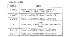
図2は、α係数に対応した演算式を示す図である。α係数は、汎用データテーブル32にマッピングされているスプライト属性テーブルに設定されている。αブレンディングは、複数の画像をα係数を使って半透明合成する処理である。具体的には、次のように行う。
Next, α blending performed by the
FIG. 2 is a diagram illustrating an arithmetic expression corresponding to the α coefficient. The α coefficient is set in a sprite attribute table mapped to the general-purpose data table 32. α blending is a process of translucently combining a plurality of images using an α coefficient. Specifically, this is performed as follows.
フレームバッファ25へスプライトを描画するときに、フレームバッファ25に描画しようとするデータ(前レイヤ:fore layerのカラーデータ)とすでに描画されているデータ(後レイヤ:back layerのカラーデータ)との間で、α係数に従い図2に示す演算を行う。この演算を行った結果を描画する機能がαブレンディングである。例えば、α係数が「00000」の場合、図2に示す複数の演算式における1番上の演算式が用いられ、その演算結果を描画する。
When drawing a sprite to the
次に、上記αブレンディングを行う回路構成について、図3及び図4を参照して説明する。図3は、画像処理装置20内のレンダリングプロセッサ24で構成されているαブレンディング回路を示すブロックである。αブレンディング回路は、上記フレームバッファ25と、αブレンディングモジュール41とで構成されている。αブレンディングモジュール41は、上記レンダリングプロセッサ24の一部として構成されている。
Next, a circuit configuration for performing the α blending will be described with reference to FIGS. FIG. 3 is a block diagram showing an α blending circuit composed of the
αブレンディングモジュール41は、先ず、フレームバッファ25における描画しようとする位置にすでに描画されているデータ(後レイヤのカラーデータ=リードデータ)を、そのフレームバッファ25から読み出す。次いで、αブレンディングモジュール41は、フレームバッファ25に描画しようとするデータ(前レイヤのカラーデータ=レンダリングデータ)と、フレームバッファ25から読み出されたリードデータとの間で、α係数に従いαブレンディングを実行する。そして、αブレンディングモジュール41は、αブレンディングされたデータをフレームバッファ25に書き込む。
αブレンディングモジュール41は、αブレンディングとして例えば下記数式(1)の計算を行う。
(32−α)/32×(rendering data)+α/32×(read data) …(1)
First, the
The
(32−α) / 32 × (rendering data) + α / 32 × (read data) (1)
図4は、αブレンディングモジュール41の具体的な構成例を示す回路図である。αブレンディングモジュール41は、上記数式(1)の計算を実行する回路である。αブレンディングモジュール41は、セレクタ51,52,53,54,55と、全加算機56,57,58,59,60と、シフター61,62,63,64,65とを有して構成されている。セレクタ51,52,53,54,55は、レンダリングデータとリードデータとのうちで、α係数で指定される方を選択して出力する。
FIG. 4 is a circuit diagram illustrating a specific configuration example of the
具体的にはセレクタ51は、レンダリングデータとリードデータとのうち、α係数の最下位ビットで指定される方を出力する。すなわち、α係数の最下位ビットが「0」を示せばレンダリングデータを、「1」を示せばリードデータを選択して出力する。同様に、セレクタ52,53,54,55は、レンダリングデータとリードデータとのうち、α係数の第1,2,3,4ビットで指定される方をそれぞれ出力する。
Specifically, the
全加算機56は、レンダリングデータとセレクタ51の出力とを加算して出力する。シフター61は、全加算機56の7ビットの出力の上位側の6ビットを出力する。同様に、全加算機57,58,59,60は、シフター61,62,63,64の出力とセレクタ52,53,54,55の出力とを加算してそれぞれ出力する。シフター65は、全加算機60の7ビットの出力の上位側の6ビットを出力する。
そして、シフター65の出力がαブレンディングモジュール41の出力、すなわち上記数式(1)の計算結果となる。
The
The output of the
例えばα係数が「00000」の場合は、レンダリングデータのカラーデータをそのままαブレンディングモジュール41が出力する。α係数が「00001」の場合は、レンダリングデータ×31/32+リードデータ×1/32がαブレンディングモジュール41の出力となる。そして、α係数の値が大きくなるほどレンダリングデータが小さくリードデータが大きく重み付けされてαブレンディングモジュール41の出力となる。α係数が「11111」の場合は、レンダリングデータ×1/32+リードデータ×31/32がαブレンディングモジュール41の出力となる。
したがって、αブレンディングモジュール41の出力は、レンダリングデータとリードデータとをα係数を重み付けとしてカラー合成し、その合成結果をカラーデータとして出力する。
For example, when the α coefficient is “00000”, the
Therefore, the output of the
(第1カラー演算方法)
次に、本実施形態に係る画像処理装置20で実行される第1カラー演算方法(処理)であって、表示優先順位の高いスプライトから描画した場合の複数スプライトのカラー演算方法(処理)について説明する。
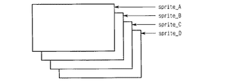
図5は、4つのスプライトが重なった状態を示す模式概念図である。図5に示すように、4つのスプライトが重なった場合の第1カラー演算方法について説明する。SpriteAは最上位スプライトすなわち優先順位が1番高いスプライトである。SpriteBは、優先順位が2番目のスプライトである。SpriteCは、優先順位が3番目のスプライトである。SpriteDは、最下位スプライトすなわち優先順位が4番目のスプライトである。
まず、第1カラー演算方法を実現するための回路構成について図6を参照して説明する。図6は、表示優先順位の高いスプライトから描画した場合の複数スプライトのカラー演算処理を行う回路、すなわち第1カラー演算処理実行回路を示すブロック図である。
(First color calculation method)
Next, a first color calculation method (process) executed by the
FIG. 5 is a schematic conceptual diagram showing a state in which four sprites are overlapped. As shown in FIG. 5, the first color calculation method when four sprites overlap will be described. Sprite A is the highest level sprite, that is, the highest priority sprite. Sprite B is the second priority sprite. SpriteC is the third priority sprite. SpriteD is the lowest-order sprite, that is, the fourth-order priority sprite.
First, a circuit configuration for realizing the first color calculation method will be described with reference to FIG. FIG. 6 is a block diagram showing a circuit that performs color calculation processing of a plurality of sprites when drawing from a sprite having a high display priority, that is, a first color calculation processing execution circuit.
第1カラー演算処理回路は、フレームバッファ25と、α係数計算モジュール71と、α係数バッファ72と、αブレンディングモジュール73とで構成されている。第1カラー演算回路は、図1に示す画像処理装置20の構成要素として形成されているものである。フレームバッファ25は、上述のように複数のキャラクタで構成される画面データ(フレームデータ)を保持するためのバッファである。
The first color arithmetic processing circuit includes a
α係数計算モジュール71は、ブレンディング実行時に下位面(下位層)に対するα係数を計算し、その計算結果のα係数をα係数バッファ72に格納させるモジュールである。α係数バッファ72は、表示画像の各画素に対応させてα係数を格納するバッファである。αブレンディングモジュール73は、下位面描画時に描画データ、描画済みデータ及びα係数バッファ72に格納されているデータを用いてαブレンディングを行うモジュールである。ここで、α係数計算モジュール71、α係数バッファ72及びαブレンディングモジュール73は、上記レンダリングプロセッサ24の構成要素としてもよい。α係数バッファ72は、汎用データテーブル32にマッピングされているものとしてもよい。
The α
次に、図5に示すように4つのスプライトが重なった場合の第1カラー演算方法について説明する。
SpriteAのRGBデータをDa、SpriteAのα係数をαa、SpriteBのRGBデータをDb、SpriteBのα係数をαb、SpriteCのRGBデータをDc、SpriteCのα係数をαc、SpriteDのRGBデータをDdとする。SpriteDは、最下位スプライトであるためαブレンディングは実行しない。
Next, a first color calculation method when four sprites overlap as shown in FIG. 5 will be described.
SpriteA RGB data is Da, SpriteA alpha coefficient is αa, SpriteB RGB data is Db, SpriteB alpha coefficient is αb, SpriteC RGB data is Dc, SpriteC alpha coefficient is αc, and SpriteD RGB data is Dd. . Since Sprite D is the lowest-order sprite, α blending is not executed.
そして、図5に示すように4つのスプライトが重なった場合の第1カラー演算方法に係るカラー演算式は下記数式(2)のようになる。
(32−αa)/32×Da+
αa/32×{(32−αb)/32×Db+
αb/32×〔(32−αc)/32×Dc+
αc/32×Dd〕} …(2)
Then, as shown in FIG. 5, the color calculation formula according to the first color calculation method when the four sprites are overlapped is expressed by the following formula (2).
(32−αa) / 32 × Da +
αa / 32 × {(32−αb) / 32 × Db +
αb / 32 × [(32−αc) / 32 × Dc +
αc / 32 × Dd]} (2)
上記数式(2)を展開すると下記数式(3)のようになる。
(32−αa)/32×Da+
αa/32×(32−αb)/32×Db+
αa/32×αb/32×(32−αc)/32×Dc+
αa/32×αb/32×αc/32×Dd …(3)
When the above formula (2) is expanded, the following formula (3) is obtained.
(32−αa) / 32 × Da +
αa / 32 × (32−αb) / 32 × Db +
αa / 32 × αb / 32 × (32−αc) / 32 × Dc +
αa / 32 × αb / 32 × αc / 32 × Dd (3)
次に、図6に示す第1カラー演算処理実行回路を用いた第1カラー演算方法について具体的に説明する。
最初に、αブレンディングモジュール73は、SpriteAをフレームバッファ25に描画する。第1カラー演算方法では、フレームバッファ25へは表示優先順位の高いスプライトから描画する。このときSpriteAはカラー演算が有効であるので、αブレンディングモジュール73は、SpriteAのデータとα係数との間で計算を行いその計算結果をフレームバッファ25に書き込む。このフレームバッファ25に書き込むデータFDaは下記数式(4)により計算される。
FDa=(32−αa)/32×Da …(4)
同時に、α係数計算モジュール71は、α係数バッファ72にSpriteAのα係数(αa)を書き込む。
Next, the first color calculation method using the first color calculation processing execution circuit shown in FIG. 6 will be specifically described.
First, the
FDa = (32−αa) / 32 × Da (4)
At the same time, the α
次いで、SpriteBを描画する。このとき、SpriteBはカラー演算が有効であるので、αブレンディングモジュール73及びα係数計算モジュール71は、SpriteBのデータと、SpriteBのα係数と、フレームバッファ25に書き込まれているデータFDaとを用いて、下記数式(5)、数式(6)に示す計算を行い、その計算結果をフレームバッファ25及びα係数バッファ72に書き込む。下記数式(5)はαブレンディングモジュール73で行われる計算であり、その計算結果であるデータFDabはフレームバッファ25に書き込まれる。
FDab=FDa+αa/32×(32−αb)/32×Db …(5)
下記数式(6)はα係数計算モジュール71で行われる計算であり、その計算結果であるα係数はα係数バッファ72に書き込まれる。
α係数=αa×αb …(6)
Next, Sprite B is drawn. At this time, since color calculation is effective for Sprite B, the
FDab = FDa + αa / 32 × (32−αb) / 32 × Db (5)
The following equation (6) is a calculation performed by the α
α coefficient = αa × αb (6)
次いで、SpriteCを描画する。このとき、SpriteCはカラー演算が有効であるので、αブレンディングモジュール73及びα係数計算モジュール71は、SpriteCのデータと、SpriteCのα係数と、フレームバッファ25に書き込まれているデータFDabと、α係数バッファ72に書き込まれているデータ(α係数=αa×αb)とを用いて、下記数式(7)、数式(8)に示す計算を行い、その計算結果をフレームバッファ25及びα係数バッファ72に書き込む。下記数式(7)はαブレンディングモジュール73で行われる計算であり、その計算結果であるデータFDabcはフレームバッファ25に書き込まれる。
FDabc=FDab+
αa/32×αb/32×(32−αc)/32×Dc …(7)
下記数式(11)はα係数計算モジュール71で行われる計算であり、その計算結果であるα係数はα係数バッファ72に書き込まれる。
α係数=αa×αb×αc …(8)
Next, SpriteC is drawn. At this time, since color calculation is effective for Sprite C, the
FDabc = FDab +
αa / 32 × αb / 32 × (32−αc) / 32 × Dc (7)
The following equation (11) is a calculation performed by the α
α coefficient = αa × αb × αc (8)
最後に、最上位面のSpriteDを描画する。このとき、SpriteDはカラー演算が無効であるので、αブレンディングモジュール73及びα係数計算モジュール71は、SpriteDのデータと、SpriteDのα係数と、フレームバッファ25に書き込まれているデータFDabcと、α係数バッファ72に書き込まれているデータ(α係数=αa×αb×αc)とを用いて、下記数式(9)に示す計算を行い、その計算結果をフレームバッファ25に書き込む。下記数式(9)はαブレンディングモジュール73で行われる計算であり、その計算結果であるデータFDabcdはフレームバッファ25に書き込まれる。
FDabcd=FDabc+
αa/32×αb/32×αc/32×Dd …(9)
また、α係数計算モジュール71は、α係数バッファ72へ「0」を示すデータを書き込む。
Finally, Sprite D on the uppermost surface is drawn. At this time, since the color calculation of SpriteD is invalid, the
FDabcd = FDabc +
αa / 32 × αb / 32 × αc / 32 × Dd (9)
In addition, the α
これらにより、第1カラー演算方法では、フレームバッファ25に対して表示優先順位の高いスプライトから描画することができ、かつ、カラー演算(αブレンディング)をすることができる。また、カラー演算しない場合には、すでに描画済の領域の描画は不要になるため、第1カラー演算方法によれば従来よりも描画性能を向上させることができる。
As a result, in the first color calculation method, drawing can be performed from a sprite having a high display priority with respect to the
(第2カラー演算方法)
次に、表示優先順位の低いスプライトから描画した場合の複数スプライトのカラー表示方法(第2カラー演算方法)について説明する。第2カラー演算方法は従来の画像処理装置で用いられているカラー演算方法である。本実施形態に係る画像処理装置20は、この表示優先順位の低いスプライトから描画した場合の複数スプライトのカラー表示方法を実行することもできるが、上記第1カラー演算方法によって従来の画像処理装置よりも描画性能を向上させることができる。
(Second color calculation method)
Next, a color display method (second color calculation method) of a plurality of sprites when drawing from a sprite having a low display priority will be described. The second color calculation method is a color calculation method used in a conventional image processing apparatus. The
図5に示すように、SpriteAのRGBデータをDa、SpriteAのα係数をαa、SpriteBのRGBデータをDb、SpriteBのα係数をαb、SpriteCのRGBデータをDc、SpriteCのα係数をαc、SpriteDのRGBデータをDdとする。SpriteDは、最下位スプライトであるためαブレンディングは実行しない。
最初に、SpriteDをフレームバッファ25に描画する。第2カラー演算方法では、フレームバッファ25へは表示優先順位の低いスプライトから描画する。
As shown in FIG. 5, the RGB data of Sprite A is Da, the α coefficient of Sprite A is αa, the RGB data of Sprite B is Db, the α coefficient of Sprite B is αb, the RGB data of Sprite C is Dc, the α coefficient of Sprite C is α c, and Sprite D RGB data of Dd is Dd. Since Sprite D is the lowest-order sprite, α blending is not executed.
First, Sprite D is drawn in the
次いで、SpriteCを描画する。このとき、SpriteCはカラー演算が有効であるので、SpriteDとSpriteCとについてカラー演算を実行した結果をフレームバッファ25に書き込む。このときフレームバッファ25に書き込む値をDcdとする。Dcdの演算は下記数式(10)のように行う。
Dcd=(32−αc)/32×Dc+αc/32×Dd …(10)
Next, SpriteC is drawn. At this time, since the color calculation is effective for Sprite C, the result of executing the color calculation for Sprite D and Sprite C is written in the
Dcd = (32−αc) / 32 × Dc + αc / 32 × Dd (10)
次いで、SpriteBを描画する。このとき、SpriteBはカラー演算が有効であるので、現在フレームバッファ25に描画されている値(Dcd)とSpriteBとについてカラー演算した結果をフレームバッファ25に書き込む。このときフレームバッファ25に書き込む値をDbcdとする。Dbcdの演算は下記数式(11)のように行う。
Dbcd=(32−αb)/32×Db+αb/32×Dcd …(11)
Next, Sprite B is drawn. At this time, since color calculation is effective for Sprite B, the value (Dcd) currently drawn in the
Dbcd = (32−αb) / 32 × Db + αb / 32 × Dcd (11)
最後に、最上位面のSpriteAを描画する。このとき、SpriteAはカラー演算が有効であるので、現在フレームバッファ25に描画されている値(Dbcd)とSpriteAとについてカラー演算した結果をフレームバッファ25に書き込む。このときフレームバッファ25に書き込む値をDabcdとする。Dabcdの演算は下記数式(12)のように行う。
Dabcd=(32−αa)/32×Da+αa/32×Dbcd …(12)
Finally, Sprite A on the top surface is drawn. At this time, since color calculation is effective for Sprite A, the value (Dbcd) currently drawn in the
Dabcd = (32−αa) / 32 × Da + αa / 32 × Dbcd (12)
このように、表示優先順位の低いスプライトから描画することにより、複数面のカラー演算を実現することができる。
上記第2カラー演算方法のように、表示優先順位の低いスプライトから描画すると、必ず全スプライトをフレームバッファ25に描画する必要がある。このため、描画性能が上がらないというデメリットがある。一方、上記第1カラー演算方法のように、表示優先順位の高いスプライトから描画すると、カラー演算を行わない場合には、既に描画済みのドットは描画しなくてもよいため、描画性能を向上させることができるというメリットが生じる。しかし、従来においては、表示優先順位の高いスプライトから描画すると、複数面のカラー演算を実現することができなかった。
As described above, by performing drawing from a sprite having a low display priority, it is possible to realize color calculation of a plurality of surfaces.
When drawing is performed from a sprite having a low display priority as in the second color calculation method, all sprites must be drawn in the
そこで、本発明の実施形態に係る画像処理装置20は、上記第1カラー演算方法により、表示優先順位の高いスプライトから描画することができ、かつ複数面についてのカラー演算を実行できるので、上記第2カラー演算方法しか実行できない従来の画像処理装置よりも描画性能を向上させることができる。
Therefore, the
以上、本発明の実施形態について図面を参照して詳述してきたが、具体的な構成はこの実施形態に限られるものではなく、本発明の要旨を逸脱しない範囲の設計変更等も含まれる。 As mentioned above, although embodiment of this invention was explained in full detail with reference to drawings, the specific structure is not restricted to this embodiment, The design change etc. of the range which does not deviate from the summary of this invention are included.
以上の説明では、本発明に係る画像処理装置20がカラー演算(αブレンディング)を行う実施形態について説明したが、本発明はこれに限定されるものではなく、画像処理装置20がカラー演算の代わりに(又はカラー演算とともに)ピクセル演算を行うものとしてもよい。すなわち、画像処理装置20は、表示優先順位の高いスプライトから描画することができ、かつ、複数面についてのピクセル演算を行うことができるものとしてもよい。なお、ピクセル演算とは、乗算演算、加算演算などである。
また、上記実施形態では、画像処理装置20をすべてハードウェアで構成することとしたが、本発明はこれに限定されるものではなく、本発明に係る画像処理装置の一部構成をソフトウェアで実現してもよい。
In the above description, the embodiment in which the
In the above embodiment, the
1…画像表示装置、11…CGメモリ、12…CPU、13…モニタ、20…画像処理装置、21…CGメモリインターフェース、22…リアルタイムデコーダ、23…スプライトバッファ、24…レンダリングプロセッサ、25…フレームバッファ、26…フレームデータ制御回路、27…D/Aコンバータ、28…スプライト・プレーン・ジェネレータ、29…CPUインターフェース、30…DMA制御回路、31…カラーパレット、32…汎用データテーブル、33…レジスタ、34…モニタ制御回路、35…クロック生成回路、41…αブレンディングモジュール、51,52,53,54,55…セレクタ、56,57,58,59,60…全加算機、61,62,63,64,65…シフター、71…α係数計算モジュール、72…α係数バッファ、73…αブレンディングモジュール
DESCRIPTION OF
Claims (4)
前記表示画像データの各画素に対応させて設定されている係数データであると共に、各画素位置の透過度情報を示す係数データであるα係数を格納するα係数バッファと、
前記α係数を使って2つの画像を半透明合成する処理であるαブレンディングの実行時に、該2つの画像における表示優先度が低い方の画像である下位面に対するα係数を計算し、該α係数を前記α係数バッファに格納させるα係数計算モジュールと、
前記2つの画像における表示優先度が高い方の画像である上位面又は前記下位面を前記フレームバッファに描画するときに、描画データ、描画済みデータ及び前記α係数バッファに格納されているデータを用いてαブレンディングを行うと共に、該上位面のスプライトを前記フレームバッファに描画した後に、該下位面のスプライトを該フレームバッファに描画するαブレンディングモジュールとを有することを特徴とする画像処理装置。 A frame buffer for holding display image data output to the display means in a bitmap format;
An α coefficient buffer that stores coefficient data that is coefficient data that is set corresponding to each pixel of the display image data, and that is coefficient data indicating the transparency information of each pixel position;
When executing α blending, which is a process of translucently synthesizing two images using the α coefficient, an α coefficient is calculated for a lower surface that is an image with a lower display priority in the two images, and the α coefficient An α coefficient calculation module for storing in the α coefficient buffer;
When drawing the upper surface or the lower surface, which has the higher display priority in the two images, in the frame buffer, the drawing data, the drawn data, and the data stored in the α coefficient buffer are used. And an α blending module that renders the lower surface sprite in the frame buffer after the upper surface sprite is rendered in the frame buffer.
前記表示画像データの各画素に対応させて設定されている係数データであると共に、2つの画像を重ねてなる合成画像の各画素データを算出するピクセル演算に用いる係数データを格納する係数バッファと、
前記ピクセル演算を算出するときに、前記2つの画像における表示優先度が低い方の画像である下位面に対する前記係数データを計算し、該係数データを前記係数バッファに格納させる係数計算モジュールと、
前記2つの画像における表示優先度が高い方の画像である上位面又は前記下位面を前記フレームバッファに描画するときに、描画データ、描画済みデータ及び前記係数バッファに格納されているデータを用いて前記ピクセル演算を行うと共に、該上位面のスプライトを前記フレームバッファに描画した後に、該下位面のスプライトを該フレームバッファに描画するピクセル演算モジュールとを有することを特徴とする画像処理装置。 A frame buffer for holding display image data output to the display means in a bitmap format;
A coefficient buffer that stores coefficient data that is coefficient data set in correspondence with each pixel of the display image data and that is used for pixel calculation to calculate each pixel data of a composite image formed by overlapping two images;
A coefficient calculation module that calculates the coefficient data for a lower surface, which is an image having a lower display priority in the two images, and stores the coefficient data in the coefficient buffer when calculating the pixel operation;
When drawing the upper surface or the lower surface, which is the image with the higher display priority in the two images, in the frame buffer, the drawing data, the drawn data, and the data stored in the coefficient buffer are used. An image processing apparatus, comprising: a pixel calculation module that performs the pixel calculation and draws the lower surface sprite in the frame buffer after drawing the upper surface sprite in the frame buffer.
前記α係数を使って2つの画像を半透明合成する処理であるαブレンディング実行時は、該2つの画像における表示優先度が低い方の画像である下位面に対するα係数を計算し、該α係数を前記α係数バッファに格納し、
前記2つの画像における表示優先度が高い方の画像である上位面又は前記下位面を前記フレームバッファに描画するときは、描画データ、描画済みデータ及び前記α係数バッファに格納されているデータを用いてαブレンディングを行うと共に、該上位面のスプライトを前記フレームバッファに描画した後に、該下位面のスプライトを該フレームバッファに描画することを特徴とする画像処理方法。 The display image is frame-buffered using an α coefficient buffer that stores coefficient data that is coefficient data set corresponding to each pixel of the display image and that is coefficient data indicating the transparency information of each pixel position. An image processing method of temporarily holding and displaying on a display means,
When executing α blending, which is a process of translucently synthesizing two images using the α coefficient, the α coefficient for the lower surface, which is the image with the lower display priority in the two images, is calculated, and the α coefficient In the α coefficient buffer,
When drawing the upper surface or the lower surface, which is the image with the higher display priority in the two images, in the frame buffer, the drawing data, the drawn data, and the data stored in the α coefficient buffer are used. An image blending method, and after drawing the upper surface sprite in the frame buffer, drawing the lower surface sprite in the frame buffer.
前記合成画像を算出するときに、前記2つの画像における表示優先度が低い方の画像である下位面に対する前記係数データを計算し、該係数データを前記係数バッファに格納し、
前記2つの画像における表示優先度が高い方の画像である上位面又は前記下位面を前記フレームバッファに描画するときは、描画データ、描画済みデータ及び前記係数バッファに格納されているデータを用いて前記ピクセル演算を行うと共に、該上位面のスプライトを前記フレームバッファに描画した後に、該下位面のスプライトを該フレームバッファに描画することを特徴とする画像処理方法。
A coefficient buffer that stores coefficient data that is coefficient data that is set in correspondence with each pixel of the display image and that is used for pixel calculation to calculate each pixel data of a composite image that is a combination of two images. An image processing method for temporarily holding the display image in a frame buffer and displaying the display image on a display means,
When calculating the composite image, calculate the coefficient data for the lower surface, which is the image with the lower display priority in the two images, store the coefficient data in the coefficient buffer,
When drawing the upper surface or the lower surface, which is the image with the higher display priority in the two images, in the frame buffer, the drawing data, the drawn data, and the data stored in the coefficient buffer are used. An image processing method characterized by performing the pixel calculation and drawing the upper surface sprite in the frame buffer and then drawing the lower surface sprite in the frame buffer.
Priority Applications (2)
| Application Number | Priority Date | Filing Date | Title |
|---|---|---|---|
| JP2003305273A JP2005077522A (en) | 2003-08-28 | 2003-08-28 | Image processor and image processing method |
| US10/927,558 US20050046635A1 (en) | 2003-08-28 | 2004-08-26 | Apparatus and method for processing images and drawing sprites in priority order by alfa blending on display screen |
Applications Claiming Priority (1)
| Application Number | Priority Date | Filing Date | Title |
|---|---|---|---|
| JP2003305273A JP2005077522A (en) | 2003-08-28 | 2003-08-28 | Image processor and image processing method |
Publications (2)
| Publication Number | Publication Date |
|---|---|
| JP2005077522A true JP2005077522A (en) | 2005-03-24 |
| JP2005077522A5 JP2005077522A5 (en) | 2005-11-04 |
Family
ID=34214052
Family Applications (1)
| Application Number | Title | Priority Date | Filing Date |
|---|---|---|---|
| JP2003305273A Pending JP2005077522A (en) | 2003-08-28 | 2003-08-28 | Image processor and image processing method |
Country Status (2)
| Country | Link |
|---|---|
| US (1) | US20050046635A1 (en) |
| JP (1) | JP2005077522A (en) |
Cited By (8)
| Publication number | Priority date | Publication date | Assignee | Title |
|---|---|---|---|---|
| JP2007226444A (en) * | 2006-02-22 | 2007-09-06 | Nec Electronics Corp | Image composition apparatus and image composition method thereof |
| JP2010039139A (en) * | 2008-08-04 | 2010-02-18 | Toshiba Corp | Mobile terminal |
| JP2010514012A (en) * | 2006-12-15 | 2010-04-30 | クゥアルコム・インコーポレイテッド | Post-render graphics transparency |
| JP2011033651A (en) * | 2009-07-29 | 2011-02-17 | Yamaha Corp | Video processing device |
| JP5384713B1 (en) * | 2012-10-29 | 2014-01-08 | 株式会社藤商事 | Game machine |
| WO2014097482A1 (en) * | 2012-12-21 | 2014-06-26 | 三菱電機株式会社 | Pixel combination apparatus |
| US9305251B2 (en) | 2012-12-04 | 2016-04-05 | Konica Minolta, Inc. | Image processing apparatus and computer readable storage medium stored with control program of image processing apparatus |
| JP2018005226A (en) * | 2016-07-05 | 2018-01-11 | ユビタス インコーポレイテッドUbitus Inc. | System and method for overlaying multi-source media in vram (video random access memory) |
Families Citing this family (4)
| Publication number | Priority date | Publication date | Assignee | Title |
|---|---|---|---|---|
| US20060268014A1 (en) * | 2005-05-27 | 2006-11-30 | Jiliang Song | System and method for efficiently supporting image deformation procedures in an electronic device |
| WO2007088827A1 (en) * | 2006-01-31 | 2007-08-09 | Nec Corporation | Content display method content display device and program |
| JP2008244981A (en) * | 2007-03-28 | 2008-10-09 | Seiko Epson Corp | Video synthesis device and video output device |
| KR101769150B1 (en) | 2010-11-08 | 2017-08-17 | 삼성전자주식회사 | Method for updating media database in a portable terminal |
Family Cites Families (2)
| Publication number | Priority date | Publication date | Assignee | Title |
|---|---|---|---|---|
| US5625764A (en) * | 1993-03-16 | 1997-04-29 | Matsushita Electric Industrial Co., Ltd. | Weighted average circuit using digit shifting |
| JP4399910B2 (en) * | 1998-09-10 | 2010-01-20 | 株式会社セガ | Image processing apparatus and method including blending processing |
-
2003
- 2003-08-28 JP JP2003305273A patent/JP2005077522A/en active Pending
-
2004
- 2004-08-26 US US10/927,558 patent/US20050046635A1/en not_active Abandoned
Cited By (9)
| Publication number | Priority date | Publication date | Assignee | Title |
|---|---|---|---|---|
| JP2007226444A (en) * | 2006-02-22 | 2007-09-06 | Nec Electronics Corp | Image composition apparatus and image composition method thereof |
| JP2010514012A (en) * | 2006-12-15 | 2010-04-30 | クゥアルコム・インコーポレイテッド | Post-render graphics transparency |
| JP2010039139A (en) * | 2008-08-04 | 2010-02-18 | Toshiba Corp | Mobile terminal |
| JP2011033651A (en) * | 2009-07-29 | 2011-02-17 | Yamaha Corp | Video processing device |
| JP5384713B1 (en) * | 2012-10-29 | 2014-01-08 | 株式会社藤商事 | Game machine |
| JP2014087402A (en) * | 2012-10-29 | 2014-05-15 | Fujishoji Co Ltd | Game machine |
| US9305251B2 (en) | 2012-12-04 | 2016-04-05 | Konica Minolta, Inc. | Image processing apparatus and computer readable storage medium stored with control program of image processing apparatus |
| WO2014097482A1 (en) * | 2012-12-21 | 2014-06-26 | 三菱電機株式会社 | Pixel combination apparatus |
| JP2018005226A (en) * | 2016-07-05 | 2018-01-11 | ユビタス インコーポレイテッドUbitus Inc. | System and method for overlaying multi-source media in vram (video random access memory) |
Also Published As
| Publication number | Publication date |
|---|---|
| US20050046635A1 (en) | 2005-03-03 |
Similar Documents
| Publication | Publication Date | Title |
|---|---|---|
| JPH05307610A (en) | Texture mapping method and its device | |
| US7554554B2 (en) | Rendering apparatus | |
| JP2005077522A (en) | Image processor and image processing method | |
| JP3770121B2 (en) | Image processing device | |
| JP5515487B2 (en) | Image processing device | |
| JP2001209789A (en) | Graphic accelerator and plotting method | |
| JP2012032456A (en) | Image processing apparatus | |
| JP2003051023A (en) | Device, method and program for plotting and computer readable recording medium with the same program recorded | |
| JP2003308537A (en) | Graphic rendering device | |
| JP3481913B2 (en) | Image processing device | |
| JPH10247241A (en) | Convolution scanning line rendering | |
| JP3910259B2 (en) | Image processing apparatus and method, and rendering apparatus and method | |
| JPH09319892A (en) | Image processor and its processing method | |
| JP2004213464A (en) | Image processor | |
| JP3556517B2 (en) | 3D image processing device | |
| JP3872056B2 (en) | Drawing method | |
| JP3701557B2 (en) | Image display control method and apparatus, and computer-readable recording medium | |
| JPH08286658A (en) | Resolution converting device and resolution converting method | |
| JP3652586B2 (en) | Image drawing system | |
| JP3971448B2 (en) | Drawing apparatus and drawing method | |
| JP2989627B2 (en) | Video display device | |
| JP4194605B2 (en) | Image processing apparatus and method, and rendering apparatus and method | |
| JPH041356B2 (en) | ||
| JP4563070B2 (en) | GAME DEVICE AND GAME PROGRAM | |
| JPH08129368A (en) | Graphics subsystem and control method therefor |
Legal Events
| Date | Code | Title | Description |
|---|---|---|---|
| A521 | Request for written amendment filed |
Free format text: JAPANESE INTERMEDIATE CODE: A523 Effective date: 20050909 |
|
| A977 | Report on retrieval |
Free format text: JAPANESE INTERMEDIATE CODE: A971007 Effective date: 20060213 |
|
| A131 | Notification of reasons for refusal |
Free format text: JAPANESE INTERMEDIATE CODE: A131 Effective date: 20060228 |
|
| A02 | Decision of refusal |
Free format text: JAPANESE INTERMEDIATE CODE: A02 Effective date: 20060704 |